EP3254357B1 - Moteur électrique et ensemble de connexion pour celui-ci - Google Patents
Moteur électrique et ensemble de connexion pour celui-ci Download PDFInfo
- Publication number
- EP3254357B1 EP3254357B1 EP16705443.6A EP16705443A EP3254357B1 EP 3254357 B1 EP3254357 B1 EP 3254357B1 EP 16705443 A EP16705443 A EP 16705443A EP 3254357 B1 EP3254357 B1 EP 3254357B1
- Authority
- EP
- European Patent Office
- Prior art keywords
- slot
- insulation
- displacement
- contact
- electric motor
- Prior art date
- Legal status (The legal status is an assumption and is not a legal conclusion. Google has not performed a legal analysis and makes no representation as to the accuracy of the status listed.)
- Active
Links
Images



Classifications
-
- H—ELECTRICITY
- H02—GENERATION; CONVERSION OR DISTRIBUTION OF ELECTRIC POWER
- H02K—DYNAMO-ELECTRIC MACHINES
- H02K3/00—Details of windings
- H02K3/46—Fastening of windings on the stator or rotor structure
- H02K3/52—Fastening salient pole windings or connections thereto
- H02K3/521—Fastening salient pole windings or connections thereto applicable to stators only
- H02K3/522—Fastening salient pole windings or connections thereto applicable to stators only for generally annular cores with salient poles
-
- H—ELECTRICITY
- H01—ELECTRIC ELEMENTS
- H01R—ELECTRICALLY-CONDUCTIVE CONNECTIONS; STRUCTURAL ASSOCIATIONS OF A PLURALITY OF MUTUALLY-INSULATED ELECTRICAL CONNECTING ELEMENTS; COUPLING DEVICES; CURRENT COLLECTORS
- H01R4/00—Electrically-conductive connections between two or more conductive members in direct contact, i.e. touching one another; Means for effecting or maintaining such contact; Electrically-conductive connections having two or more spaced connecting locations for conductors and using contact members penetrating insulation
- H01R4/24—Connections using contact members penetrating or cutting insulation or cable strands
- H01R4/2416—Connections using contact members penetrating or cutting insulation or cable strands the contact members having insulation-cutting edges, e.g. of tuning fork type
- H01R4/242—Connections using contact members penetrating or cutting insulation or cable strands the contact members having insulation-cutting edges, e.g. of tuning fork type the contact members being plates having a single slot
- H01R4/2425—Flat plates, e.g. multi-layered flat plates
- H01R4/2429—Flat plates, e.g. multi-layered flat plates mounted in an insulating base
-
- H—ELECTRICITY
- H02—GENERATION; CONVERSION OR DISTRIBUTION OF ELECTRIC POWER
- H02K—DYNAMO-ELECTRIC MACHINES
- H02K5/00—Casings; Enclosures; Supports
- H02K5/04—Casings or enclosures characterised by the shape, form or construction thereof
- H02K5/08—Insulating casings
-
- H—ELECTRICITY
- H02—GENERATION; CONVERSION OR DISTRIBUTION OF ELECTRIC POWER
- H02K—DYNAMO-ELECTRIC MACHINES
- H02K11/00—Structural association of dynamo-electric machines with electric components or with devices for shielding, monitoring or protection
- H02K11/30—Structural association with control circuits or drive circuits
- H02K11/33—Drive circuits, e.g. power electronics
-
- H—ELECTRICITY
- H02—GENERATION; CONVERSION OR DISTRIBUTION OF ELECTRIC POWER
- H02K—DYNAMO-ELECTRIC MACHINES
- H02K2203/00—Specific aspects not provided for in the other groups of this subclass relating to the windings
- H02K2203/03—Machines characterised by the wiring boards, i.e. printed circuit boards or similar structures for connecting the winding terminations
-
- H—ELECTRICITY
- H02—GENERATION; CONVERSION OR DISTRIBUTION OF ELECTRIC POWER
- H02K—DYNAMO-ELECTRIC MACHINES
- H02K2203/00—Specific aspects not provided for in the other groups of this subclass relating to the windings
- H02K2203/06—Machines characterised by the wiring leads, i.e. conducting wires for connecting the winding terminations
-
- H—ELECTRICITY
- H02—GENERATION; CONVERSION OR DISTRIBUTION OF ELECTRIC POWER
- H02K—DYNAMO-ELECTRIC MACHINES
- H02K2203/00—Specific aspects not provided for in the other groups of this subclass relating to the windings
- H02K2203/09—Machines characterised by wiring elements other than wires, e.g. bus rings, for connecting the winding terminations
Definitions
- the invention relates to an electric motor, in particular a radiator fan motor of a motor vehicle, with a switching unit for the coil ends of a motor or stator winding of the electric motor, according to the preamble of claim 1. It further relates to such a switching unit.
- Such an electric motor and such a switching unit are known, for example, from DE 101 52 006 A1 known.
- a brushless electric motor has a stator with a number of stator teeth, for example arranged in a star shape, which carry an electrical stator winding (motor winding) in the form of individual stator coils, which in turn are wound from an insulating wire.
- the coils are assigned to individual strands with their coil ends and are connected to one another in a predetermined manner via connecting conductors of a switching unit.
- the stator has three strands and thus at least three connecting conductors, each of which is supplied with an electric current in a phase-shifted manner in order to generate a rotating magnetic field in which a rotor or runner, usually equipped with permanent magnets, rotates.
- the connecting conductors are fed to a motor electronics unit to control the electric motor.
- the coils of the stator winding are connected to one another in a specific way using the connecting conductors.
- the type of connection is determined by the winding pattern of the stator winding, with a star connection or a delta connection of the coils being the usual winding pattern.
- the connector arrangement comprises an annular wire guide element for receiving the ends of the windings and a connection receptacle in the form of three annular connecting rails, each of which has a cable lug as an end.
- the connecting rails have axially extended wire clamps to ensure electrical contact for the three phases through the slots of the wire guide element.
- a stator for an electric motor with a ring-shaped stator package with several stator teeth is known.
- a ring-shaped connecting unit is attached to one end or face of the stator.
- the ring-shaped connecting unit comprises deflection elements and a support element which is equipped with a holder and slots.
- In the holder there is a series of mutually insulated connecting rings, each of which has contact elements which are led outwards through the slots.
- An electric motor with a stator with twelve stator windings is known, which are partially connected in series and ultimately to form a star connection.
- a support element and a conductor track structure made of four wires are provided, which are accommodated by the support element in that the wires are clipped into this support element.
- the wires form a complete ring or partial ring sections, with such a wire as a complete ring forming the star connection in connection with the coil ends of the stator windings.
- the support element has axial guides for the coil ends, with the electrical connection between the coil ends and the respective wires being made by soldering, welding or hot caulking.
- Circuit units with contact wires made of round wire for connecting and contacting the coil ends are available from the US 7,948,130 B2 and from the DE 102 61 611 A1
- contact wires made of round wire Contacting the coil ends using resistance welding is problematic because the round wire cross-sections of both the coil ends and the respective contact wire mean that the wires involved tend to tilt when welded using smooth or flat electrodes. Such tilting of the wires leads to an undesirably high reject rate due to frequent faulty welding.
- the invention is therefore based on the object of specifying an electric motor with a switching unit that is particularly suitable for simple and reliable connection and contacting of the winding coils. Furthermore, a switching unit with a number of contact wires, preferably arranged in a ring to form a connection ring, for connecting the coils is to be specified, the wire ends of which can be or are connected to one another and/or to phase connections of the motor winding in a particularly suitable manner in an electrically conductive manner.
- the electric motor has a switching unit with a number of contact wires and with a ring-shaped frame part with a number of slotted plug-in pockets.
- the contact wires are arranged to form a connection ring for the coil ends of a stator winding.
- the wire ends of the contact wires (copper wires), which are preferably provided with an insulating sheath (insulation), are connected to insulation displacement contacts, i.e. they are electrically conductively contacted with one another.
- the or each insulation displacement contact has two insulation displacement legs spaced apart from one another to form an insulation displacement slot with a slot opening on the free end for connecting at least two of the wire ends, wherein the insulation displacement contacts are seated in plug-in pockets of the frame part of the switching unit when assembled.
- the respective plug-in pocket of the frame part suitably has a at least two of the wire ends, the insulation displacement contacts being seated in the insertion pockets of the frame part of the switching unit when assembled.
- the respective insertion pocket of the frame part suitably has a slot aligned with the insulation displacement slot of the insulation displacement contact inserted into this insertion pocket.
- These slots of the insulation displacement contact and the insertion pockets on the frame part expediently run axially, i.e. in the axial direction with respect to the assembled state of the electric motor.
- An insulation displacement contact is usually a connecting element for connecting a plug element to a wire, for example also a wire provided with insulation. Such an insulation displacement contact is usually intended and designed for the insulation displacement contacting of a single wire.
- the insulation displacement contact according to the invention is designed to connect two or more wires (copper wires) to form a permanent connection.
- the insulation displacement slot and/or the insulation displacement legs of the insulation displacement contact are therefore designed in such a way that the at least two wire ends that are inserted one after the other in the longitudinal direction of the slot into the insulation displacement slot and guided there along at least one knife edge on the leg side are securely clamped together.
- the insulation displacement slot of the or each insulation displacement contact has a first slot area in the longitudinal direction of the slot, which adjoins a slot opening on the leg-free end, and an adjoining, diamond-shaped or rhombus-shaped, widened second slot area.
- the or each leg of the respective insulation displacement contact suitably has at least one raised joining contour on the outside of the leg.
- a suitable embodiment provides additionally or alternatively that the insulation displacement slot of the or each insulation displacement contact is arranged in a slot facing away from a leg-free end slot opening in the slot longitudinal direction.
- the slot end region has a preferably circular recess contour which forms a predetermined bending point (predetermined bending point) for the insulation displacement legs.
- the recess contour forms a contact contour that narrows the insulation displacement slot and against which the first wire end inserted into the insulation displacement slot strikes. This wire end then practically forms the stop for the second wire end inserted into the insulation displacement slot.
- the insulation displacement contacts suitably form a corresponding number of phase connections, for example three phase connections in a three-phase electric motor or a three-phase motor winding.
- the connections of the wire ends of the contact wires, preferably arranged to form a connection ring, made by means of the insulation displacement contacts can also be used or employed for the phase connections of a multi-phase motor or stator winding.
- the insulation displacement contact has two legs (insulation displacement legs).
- a slot insulation displacement slot is formed between the legs, which is open at the leg free ends and closed at the opposite leg ends.
- the opposite leg edges are designed in such a way that a wire (conductor) inserted into the slot from the slot opening is cut and/or incised at the leg edges (referred to below as knife edges) (on the circumference), thereby severing the wire insulation.
- the flexible legs exert a spring-like clamping force on the respective wire (the respective wire end).
- the knife edges of the insulation displacement legs run almost tangentially to the wire diameter, which is usually approximately circular.
- the cutting edge or knife edge and/or slot geometry of the insulation displacement contact is such that in the longitudinal direction of the slot both a first and at least a second wire (wire end) in the insulation displacement contact slot of the same insulation displacement contact is reliably clamped.
- a specific, predetermined and/or selected ratio of the cutting depth of the wire (wire end) to the wire diameter is produced by means of the knife edge arrangement and/or contour.
- the geometry or knife edge contour and/or slot geometry is such that a first wire (wire end) is initially pressed into the insulation displacement contact during contact and is cut at the knife edge or the two knife edges flanking the slot.
- the wire is oriented normal to the slot plane of the insulation displacement contact.
- the wire diameter is reduced by, for example, 20% to 25%, while the wire subsequently cut during contact is cut by a smaller amount, for example 10% to ⁇ 20%, in terms of its wire diameter in the area of the cutting edges.
- the or each wire is oriented normal to the slot plane of the insulation displacement contact.
- the slot geometry is such that, starting from the slot opening, a first, preferably comparatively short, cutting area is connected to it, followed by an expanded second area and then by a third, preferably comparatively long, cutting area.
- the expanded area is, for example, diamond-shaped, in that an approximately V-shaped notch is made in each of the two opposite legs. Since the insulation displacement contact is preferably a stamped part, both this geometry and another geometry or contour representing the expanded area are conceivable. In the expanded area, the edges of the legs facing each other do not necessarily have to be designed as knife edges.
- local raised contours are suitably formed on the outside of the insulation displacement legs. It is also expedient to provide raised contours on the outside along the Insulation clamping legs have additional joining contours (tenons and/or grooves) formed or punched into them.
- the widened area of the slot has the advantageous purpose and the suitable function of receiving the initially (first) wire cut in the slot as soon as the further (second) wire reaches the comparatively short or narrow cutting area adjacent to the insertion opening of the slot between the knife edges of the oppositely arranged legs. Since in this position the first wire is in the widened area of the slot, the required insulation displacement forces of the two legs act on the second wire in the cutting area in front of the slot opening. In this way, both wires are cut one after the other and can then be guided or pressed further in a clamping contact in the longitudinal direction of the slot via the widened area into the adjacent insulation displacement area, which acts in particular as a clamping area.
- the insulation displacement contact interacts with a receiving pocket adapted to its outer contour, in particular in the area of its legs.
- This is also suitably slotted, with opposite pocket-side slots being aligned with the slot of the insulation displacement contact when it is assembled.
- the joining contours formed on the outside of the insulation displacement contact enable the insulation displacement contact to be firmly seated in a force-fitting and/or positive-fitting manner within the joining or receiving pocket, so that a reliable and/or additional force is exerted on the or each contacted wire, preferably via the legs.
- the wires to be contacted can already be inserted into the slot areas of this insertion or receiving pocket when the insulation displacement contact is pressed into this joining pocket of the additional part.
- the contact that has already been insulation displacement-contacted to the two wires can then be inserted into the pocket.
- the or each joining pocket is part of the (ring-shaped) frame part of the switching unit for the circuit-technically predetermined contacting of the contact wires, coil end and/or phase connections for the stator or motor winding of the electric motor, in particular a radiator fan motor of a motor vehicle.
- connection or termination ring For contacting phase-side connections, for example, three such insulation displacement contacts with associated joining or plug-in pockets are provided in the frame part of the switching unit (connection or termination ring) and are arranged equidistant from one another, for example.
- the preferably circular ring-shaped frame part also accommodates contact wires intended for connecting the coils of the stator winding, which are contacted with the respective coil ends and/or phase connections.
- the Figures 1a and 1b show an insulation displacement contact 1, hereinafter also referred to simply as a contact, with an insulation displacement slot, hereinafter simply referred to as a slot 2, which is flanked by two, hereinafter simply referred to as legs 3 of the insulation displacement leg of the insulation displacement contact 1, i.e. is located or formed between these two legs 3.
- the contact 1 is preferably a stamped part.
- the legs 3 of the contact 1 merge into a contact head 5, preferably provided with a through-opening (through hole) 4.
- joining contours 6 are formed or stamped onto these.
- the slot 2 has a slot opening 7 in the area of the leg-free ends of the legs 3. This is followed by a first, comparatively short insulation-clamping contour 9 in the longitudinal direction 8 of the slot. This transitions into an expanded area 10 in the longitudinal direction 8 of the slot. This is preferably diamond-shaped. This area 10 is in turn followed by another, comparatively long insulation-clamping area or at least a clamping area 11. This ends at the ends opposite the leg-free ends, ie at the transition area 12 of the legs 3.
- the diameter reduction of the first wire cut in the slot 2 is, for example, approximately 22%, while the diameter reduction of the other wire cut in the slot 2 is, for example, approximately 16%, based on a copper wire with a diameter of, for example, 1.12 mm and wire insulation of, for example, 0.003 mm, i.e. a total wire diameter of approximately 1.15 mm to 1.16 mm.
- the diamond-shaped area 10 has a tapered, comparatively pronounced cutting contour 10a on the side facing the slot opening 7.
- a circular recess contour 12a is provided in the embodiment. This leads to an at least slight reduction in the leg width b of the legs 3 in comparison to the leg width of the insulation displacement contacts 1 according to the Figures 1a and 1b without such a recess contour in the transition area 12.
- This recess contour 12a defines a desired bending point 12b for the legs 3 when they bend outwards when the wires or wire ends designated 20 are inserted into the insulation displacement slot 2 of the contact 1.
- the recess contour 12a also forms a contact edge 12c that narrows the insulation displacement slot 2, for example in the form of a sector-shaped projection, as a stop inside the slot for the wire ends 20.
- Figure 3 shows an interconnection ring 18 with several contact wires 19 arranged in a circle and three equidistantly arranged insulation displacement contacts 1, each of which makes insulation displacement contact with two wires or wire ends 20.
- FIG 4 shows a switching unit 21 with such a connection ring 18.
- the switching unit 21 has an annular frame body (frame part) 22, preferably made of plastic. This in turn has a receiving pocket (plug-in/joining pocket) 23 in the area of the respective insulation displacement contact 1 for receiving the insulation displacement contact 1.
- Figure 5 shows the switching unit 21 or the frame part 22 according to Figure 4 with two insulation displacement contacts 1 inserted into the associated insertion pockets 23, while the insertion pocket 23 visible in the foreground of the figure can be seen without an insulation displacement contact 1.
- the respective frame-side slot opening 24 is located on the slot side opposite the slot opening 7 of the insulation displacement contact 1, i.e. on the insertion or insertion side of the respective insertion pocket 23.
- the contacted wire ends 20 run normal to the slot plane spanned by the slot 2.
- FIG 6 shows a further embodiment of the switching unit with complete, closed coil cassettes 26, which are formed on the frame part 22 of the switching unit 21. These take up space in the assembled state of the Figure 7 shown stator 27 of an electric motor 28 each have its stator teeth and are or will be wound with the individual coils of the stator winding in a manner not shown in detail.
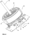
- Figure 8 shows the stator 27 provided with the switching unit 21 according to Figure 7 including rotor 29 and motor shaft 30 as well as including electronics (circuit board) 31 and their contacting with the insulation displacement contacts 1 via their contact heads 5. These are inserted into, for example, crimp-tab-like insertion pockets 32 of contacts (flat contacts) or contact sections 33 manufactured, for example, as stamped and bent parts from flat wire and form the phase connections for the three-phase current supply to the stator or motor winding.
- Figure 9 shows the assembled electric motor 28 as a radiator fan motor for a motor vehicle including stator 27, switching unit 21 and fan wheel 34.
Landscapes
- Engineering & Computer Science (AREA)
- Power Engineering (AREA)
- Microelectronics & Electronic Packaging (AREA)
- Insulation, Fastening Of Motor, Generator Windings (AREA)
- Windings For Motors And Generators (AREA)
Claims (8)
- Moteur électrique (28), comprenant une unité de commutation (21) présentant un certain nombre de connexions de phase, pourvue d'un certain nombre de fils de contact (19) et d'une partie de cadre annulaire (22),- dans lequel les fils de contact (19) sont agencés en anneau d'interconnexion (18) pour les extrémités de bobine d'un enroulement de stator, et- dans lequel la partie de cadre (22) de l'unité de commutation (21) présente un nombre de poches d'enfichage (23) correspondant au nombre des contacts autodénudants (1) pour recevoir les contacts autodénudants (1) dont chacun présente deux branches autodénudantes (3) espacées l'une par rapport à l'autre en formant une fente autodénudante (2),
caractérisé en ce que- les connexions de phase sont formées par ou comprennent un nombre correspondant de contacts autodénudants (1),- au moins deux extrémités de fil (20) des fils de contact (19) sont reliées aux contacts autodénudants (1),- la fente autodénudante (2) du ou de chaque contact autodénudant (1) présente dans la direction longitudinale de fente (8) un premier contour autodénudant (9), relativement court, adjacent à une ouverture de fente (7) côté extrémité sans branche, qui passe dans la direction longitudinale de fente (8) à une zone de fente (10) évasée en forme de losange qui est suivie d'une zone de serrage (11) supplémentaire, relativement longue, dans lequel la zone de fente évasée (10) présente sur le côté tourné vers l'ouverture de fente (7) un contour coupant (10a), relativement prononcé, qui s'amincit, et- la zone de fente évasée (10) est prévue et conçue pour recevoir la première extrémité de fil (20) d'abord entamée dans la fente autodénudante (2) dès que la deuxième extrémité de fil (20) entre dans la première zone de fente adjacente à l'ouverture de fente (7) entre les arêtes de couteau du contour autodénudant (9) des branches autodénudantes (3) disposées l'une face à l'autre. - Moteur électrique (28) selon la revendication 1, caractérisé en ce que la poche d'enfichage (23) respective de la partie de cadre (22) présente une fente (25) en affleurement avec la fente autodénudante (2) du contact autodénudant (1) enfiché dans cette poche d'enfichage (23).
- Moteur électrique (28) selon la revendication 1 ou 2, caractérisé en ce que la fente autodénudante (2) et/ou la branche autodénudante (3) du ou de chaque contact autodénudant (1) est/sont réalisée(s) de telle sorte que les au moins deux extrémités de fil (20) introduites dans la fente autodénudante (2) l'une après l'autre dans la direction longitudinale de fente (8) et guidées dans celle-ci le long d'au moins une arête de couteau (13) côté branche est/sont mise(s) en contact par serrage de façon sûre.
- Moteur électrique (28) selon l'une quelconque des revendications 1 à 3, caractérisé en ce que la deuxième zone de fente (10) de la fente autodénudante (2) du ou de chaque contact autodénudant (1) présente une forme de losange ou rhombique.
- Moteur électrique (28) selon l'une quelconque des revendications 1 à 4, caractérisé en ce que la fente autodénudante (2) du ou de chaque contact autodénudant (1) présente dans une zone d'extrémité de fente (11) détournée d'une ouverture de fente (7) dans la direction longitudinale de fente (8) un contour d'évidement (12a) qui constitue un point destiné au pliage pour les branches autodénudantes (3).
- Moteur électrique (28) selon la revendication 5, caractérisé en ce que le contour d'évidement (12a) servant de point destiné au pliage est circulaire.
- Moteur électrique (28) selon la revendication 5 ou 6, caractérisé en ce que le contour d'évidement (12a) servant de point destiné au pliage réalise un contour d'appui (12c) rétrécissant la fente autodénudante (2) comme butée pour la ou chaque extrémité de fil (20).
- Moteur électrique (28) selon l'une quelconque des revendications 1 à 7, caractérisé en ce que la ou chaque branche (3) du contact autodénudant respectif (1) présente au moins un contour d'assemblage (6) en relief du côté extérieur de la branche.
Priority Applications (1)
| Application Number | Priority Date | Filing Date | Title |
|---|---|---|---|
| EP18168825.0A EP3402047B1 (fr) | 2015-02-03 | 2016-02-03 | Contact pénétrant l'isolation |
Applications Claiming Priority (2)
| Application Number | Priority Date | Filing Date | Title |
|---|---|---|---|
| DE102015001214 | 2015-02-03 | ||
| PCT/EP2016/052267 WO2016124636A1 (fr) | 2015-02-03 | 2016-02-03 | Moteur électrique et ensemble de connexion pour celui-ci |
Related Child Applications (2)
| Application Number | Title | Priority Date | Filing Date |
|---|---|---|---|
| EP18168825.0A Division-Into EP3402047B1 (fr) | 2015-02-03 | 2016-02-03 | Contact pénétrant l'isolation |
| EP18168825.0A Division EP3402047B1 (fr) | 2015-02-03 | 2016-02-03 | Contact pénétrant l'isolation |
Publications (2)
| Publication Number | Publication Date |
|---|---|
| EP3254357A1 EP3254357A1 (fr) | 2017-12-13 |
| EP3254357B1 true EP3254357B1 (fr) | 2024-12-25 |
Family
ID=55404681
Family Applications (2)
| Application Number | Title | Priority Date | Filing Date |
|---|---|---|---|
| EP16705443.6A Active EP3254357B1 (fr) | 2015-02-03 | 2016-02-03 | Moteur électrique et ensemble de connexion pour celui-ci |
| EP18168825.0A Active EP3402047B1 (fr) | 2015-02-03 | 2016-02-03 | Contact pénétrant l'isolation |
Family Applications After (1)
| Application Number | Title | Priority Date | Filing Date |
|---|---|---|---|
| EP18168825.0A Active EP3402047B1 (fr) | 2015-02-03 | 2016-02-03 | Contact pénétrant l'isolation |
Country Status (5)
| Country | Link |
|---|---|
| US (2) | US10396616B2 (fr) |
| EP (2) | EP3254357B1 (fr) |
| KR (2) | KR101943478B1 (fr) |
| CN (2) | CN108512335B (fr) |
| WO (1) | WO2016124636A1 (fr) |
Families Citing this family (39)
| Publication number | Priority date | Publication date | Assignee | Title |
|---|---|---|---|---|
| DE102016226200A1 (de) * | 2016-12-23 | 2018-06-28 | Bühler Motor GmbH | Bürstenloser Motor |
| JP2018125951A (ja) * | 2017-01-31 | 2018-08-09 | 日本電産株式会社 | モータ及びそれを備えた送風装置 |
| DE102017209621A1 (de) * | 2017-06-08 | 2018-12-13 | Robert Bosch Gmbh | Antriebseinheit mit einem elektronisch kommutierten Motor und einer Elektronikeinheit |
| JP2019022327A (ja) * | 2017-07-18 | 2019-02-07 | 株式会社ケーヒン | 空調用ブロアモータユニット |
| DE102017212995A1 (de) | 2017-07-27 | 2019-01-31 | Brose Fahrzeugteile GmbH & Co. Kommanditgesellschaft, Würzburg | Verfahren zum Montieren einer Schalteinheit an einer Komponente eines Elektromotors |
| DE102017216084A1 (de) | 2017-09-12 | 2019-03-14 | Robert Bosch Gmbh | Stator für eine elektrische Maschine, eine elektrische Maschine und Verfahren zum Herstellen eines solchen Stators |
| DE102017216807A1 (de) * | 2017-09-22 | 2019-03-28 | Robert Bosch Gmbh | Pumpeneinrichtung mit einem Kontaktierelement |
| DE102017222076B4 (de) * | 2017-12-06 | 2025-07-03 | Brose Fahrzeugteile SE & Co. Kommanditgesellschaft, Würzburg | Elektromotor sowie Schalteinheit hierfür |
| CN110149032B (zh) * | 2018-02-12 | 2021-06-18 | 比亚迪股份有限公司 | 电机总成和具有其的车辆 |
| CN112385122B (zh) | 2018-05-08 | 2024-08-02 | 博泽沃尔兹堡汽车零部件欧洲两合公司 | 电机的定子和电机以及互连装置 |
| DE202018102652U1 (de) * | 2018-05-11 | 2019-08-14 | Brose Fahrzeugteile GmbH & Co. Kommanditgesellschaft, Würzburg | Stator für einen Elektromotor und Elektromotor sowie Schalteinheit |
| EP3651320B1 (fr) * | 2018-11-12 | 2022-05-11 | Otis Elevator Company | Support d'enroulement |
| DE102018221045A1 (de) * | 2018-12-05 | 2020-06-10 | Robert Bosch Gmbh | Stator für eine elektrische Maschine, eine elektrische Maschine und Verfahren zum Herstellen eines solchen Stators |
| JP7183799B2 (ja) * | 2019-01-09 | 2022-12-06 | 株式会社デンソー | 電気接続装置 |
| DE102019104706A1 (de) * | 2019-02-25 | 2020-08-27 | Nidec Gpm Gmbh | Elektrische Kontaktierung von Statoranschlüssen auf einer Leiterplatte mittels horizontal ausgerichteten Schneidklemmkontakten |
| EP3949084A1 (fr) * | 2019-03-28 | 2022-02-09 | Eldor Corporation S.p.A. | Dispositif de commutation pour un moteur électrique et moteur électrique comprenant ledit dispositif de commutation |
| AT522633B1 (de) * | 2019-05-29 | 2021-07-15 | Melecs Ews Gmbh | Kontaktstift, Trägerplatte und elektrische Maschine |
| DE102019121184A1 (de) | 2019-08-06 | 2021-02-11 | Schaeffler Technologies AG & Co. KG | Elektrische Maschine |
| CN112531948A (zh) * | 2019-09-18 | 2021-03-19 | 泰科电子(上海)有限公司 | 线圈骨架和定子骨架 |
| KR102241110B1 (ko) * | 2019-12-05 | 2021-04-19 | 주식회사 코아비스 | 모터 및 이를 포함한 전동식 펌프 |
| DE102020203870A1 (de) | 2020-01-24 | 2021-07-29 | Brose Fahrzeugteile SE & Co. Kommanditgesellschaft, Würzburg | Stator mit einer Kontaktvorrichtung |
| DE102020113551A1 (de) * | 2020-05-19 | 2021-11-25 | Fte Automotive Gmbh | Antriebsaggregat |
| CN113972759B (zh) * | 2020-07-24 | 2023-07-28 | 安徽威灵汽车部件有限公司 | 定子、电机、流体泵和车辆 |
| TWI739609B (zh) * | 2020-09-25 | 2021-09-11 | 大陸商深圳興奇宏科技有限公司 | 風扇定子結構製造方法 |
| TWI750823B (zh) * | 2020-09-25 | 2021-12-21 | 大陸商深圳興奇宏科技有限公司 | 風扇定子結構 |
| US12074498B2 (en) | 2020-10-08 | 2024-08-27 | Asia Vital Components (China) Co., Ltd. | Fan stator structure |
| US11894735B2 (en) | 2020-10-08 | 2024-02-06 | Asia Vital Components (China) Co., Ltd. | Manufacturing method of fan stator structure |
| JP7674121B2 (ja) * | 2021-03-18 | 2025-05-09 | ミネベアミツミ株式会社 | 遠心送風機 |
| DE112022002457T5 (de) * | 2021-05-07 | 2024-02-22 | Autonetworks Technologies, Ltd. | Mehrphasen-Motorschaltgerät und Mehrphasen-Motor |
| JP7621201B2 (ja) | 2021-06-17 | 2025-01-24 | 株式会社ミツバ | 電線接続構造および電動機 |
| JP7619187B2 (ja) * | 2021-07-01 | 2025-01-22 | 株式会社オートネットワーク技術研究所 | コイル線モジュール |
| DE102021207552A1 (de) | 2021-07-15 | 2023-01-19 | Bühler Motor GmbH | Stator für eine elektrische Antriebseinheit und Verfahren zur Herstellung eines Stators für eine elektrische Antriebseinheit |
| CN119563272B (zh) * | 2022-08-03 | 2025-10-31 | 德昌电机(江门)有限公司 | 导电连接座、定子组件及马达 |
| DE102022213212A1 (de) * | 2022-12-07 | 2024-06-13 | Brose Fahrzeugteile SE & Co. Kommanditgesellschaft, Würzburg | Stator eines Elektromotors |
| US12609574B2 (en) * | 2022-12-20 | 2026-04-21 | Mitsuba Corporation | Motor and fan device |
| DE102023205469A1 (de) * | 2023-06-13 | 2024-12-19 | Brose Fahrzeugteile SE & Co. Kommanditgesellschaft, Würzburg | Kontaktvorrichtung für einen Stator eines Elektromotors |
| DE102023206316A1 (de) * | 2023-07-04 | 2025-01-09 | Zf Friedrichshafen Ag | Antriebsanordnung für ein Fahrzeug mit einer separaten Anschlussbaugruppe sowie Verfahren zur Montage der Antriebsanordnung |
| CN120200400A (zh) * | 2023-12-22 | 2025-06-24 | 捷温有限责任公司 | 电机以及用于车辆的座椅通风系统或电池冷却系统的风扇 |
| DE102024106874A1 (de) * | 2024-03-11 | 2025-09-11 | Minebea Mitsumi Inc. | Elektromotor |
Family Cites Families (26)
| Publication number | Priority date | Publication date | Assignee | Title |
|---|---|---|---|---|
| US3950062A (en) | 1974-07-23 | 1976-04-13 | Amp Incorporated | Wire slot terminal double beam system |
| FR2419594A1 (fr) | 1978-03-07 | 1979-10-05 | Nozick Jacques | Element de contact electrique a connexion auto-denudante pour fil ou cable |
| US4287446A (en) | 1979-06-27 | 1981-09-01 | Amp Incorporated | Stator for stepper motor |
| US5088934A (en) | 1991-02-20 | 1992-02-18 | Chian Chyun Enterprise Co. Ltd. | Electrical terminal |
| DE4340032C1 (de) * | 1993-11-24 | 1994-09-01 | Hella Kg Hueck & Co | Elektrischer Verbinder |
| KR0113849Y1 (ko) | 1994-05-07 | 1998-04-15 | 안영숙 | 슬롯형 단자 및 슬롯형 단자를 구비한 단자 블록 |
| US5975919A (en) | 1997-08-26 | 1999-11-02 | Lucent Technologies Inc. | Terminal housing and wire board arrangement with solderless mountable insulation displacement connector terminals |
| US6123566A (en) * | 1998-12-21 | 2000-09-26 | Lucent Technologies Inc. | Terminal strip with integrated strain relief mechanism for an insulation displacement connector |
| JP2002151189A (ja) * | 2000-11-08 | 2002-05-24 | Yazaki Corp | 配線接続コネクタ |
| DE10129615A1 (de) | 2001-06-20 | 2003-01-02 | Delphi Tech Inc | Elektrischer Verbinder |
| DE10152006B4 (de) * | 2001-10-22 | 2011-06-01 | Zf Sachs Ag | Stator für eine elektrische Maschine |
| DE10261611A1 (de) | 2002-12-27 | 2004-07-08 | Robert Bosch Gmbh | Verschaltelement für eine Wicklung einer elektrischen Maschine |
| US7135799B2 (en) | 2003-03-19 | 2006-11-14 | Pacsci Motion Control, Inc. | Method for winding a stator of multi-phase motors |
| DE10324664A1 (de) * | 2003-05-30 | 2004-12-30 | Siemens Ag | Rollen und Rollenmotoren |
| EP1526628B1 (fr) | 2003-10-22 | 2011-03-02 | Brose Fahrzeugteile GmbH & Co. KG, Würzburg | Unité de connexion d'un stator de moteur électrique |
| JP4697403B2 (ja) * | 2005-04-14 | 2011-06-08 | 株式会社ジェイテクト | コネクタ付きモータ |
| WO2009025144A1 (fr) * | 2007-08-17 | 2009-02-26 | Kabushiki Kaisha Yaskawa Denki | Stator et machine électrique tournante l'utilisant |
| FR2923951B1 (fr) | 2007-11-19 | 2009-11-27 | Sonceboz Automotive Sa | Ensemble de connexion electrique pour moteur sans balai. |
| DE102008033905A1 (de) * | 2008-07-18 | 2010-01-21 | Wago Verwaltungsgesellschaft Mbh | Leiteranschlusselement |
| US7736173B2 (en) * | 2008-09-16 | 2010-06-15 | Surtec Industries, Inc. | Insulation displacement contact (IDC) and IDC mounting system |
| US8418346B2 (en) | 2008-09-16 | 2013-04-16 | Surtec Industries Inc. | Wire termination tool and RJ jack for use therewith |
| TWM368223U (en) * | 2009-04-20 | 2009-11-01 | Surtec Ind Inc | A combination of the insulation displacement contact (IDC) and the connector housing |
| DE102009036128A1 (de) | 2009-08-05 | 2011-02-10 | Brose Fahrzeugteile Gmbh & Co. Kg, Hallstadt | Elektrische Komponente eines Kraftfahrzeugs |
| US9231316B2 (en) | 2011-10-14 | 2016-01-05 | Omron Corporation | Electrical terminal assembly having an insertion groove |
| ITTO20120820A1 (it) * | 2012-09-21 | 2014-03-22 | Schneider Electric Ind Sas | Gruppo porta-contatti per una presa/spina di connessione elettrica |
| DE102014220201A1 (de) * | 2014-10-06 | 2016-04-07 | Bühler Motor GmbH | Elektronisch kommutierter Gleichstrommotor, insbesondere für eine Ölpumpe |
-
2016
- 2016-02-03 CN CN201810449757.7A patent/CN108512335B/zh active Active
- 2016-02-03 EP EP16705443.6A patent/EP3254357B1/fr active Active
- 2016-02-03 CN CN201680008381.5A patent/CN107210641B/zh active Active
- 2016-02-03 EP EP18168825.0A patent/EP3402047B1/fr active Active
- 2016-02-03 KR KR1020177024705A patent/KR101943478B1/ko active Active
- 2016-02-03 WO PCT/EP2016/052267 patent/WO2016124636A1/fr not_active Ceased
- 2016-02-03 KR KR1020187025496A patent/KR102055213B1/ko active Active
-
2017
- 2017-08-03 US US15/667,813 patent/US10396616B2/en active Active
-
2018
- 2018-04-25 US US15/962,040 patent/US10468932B2/en active Active
Also Published As
| Publication number | Publication date |
|---|---|
| CN107210641A (zh) | 2017-09-26 |
| KR101943478B1 (ko) | 2019-01-29 |
| CN108512335A (zh) | 2018-09-07 |
| KR20170113635A (ko) | 2017-10-12 |
| US10468932B2 (en) | 2019-11-05 |
| US10396616B2 (en) | 2019-08-27 |
| CN108512335B (zh) | 2020-06-05 |
| KR102055213B1 (ko) | 2019-12-12 |
| CN107210641B (zh) | 2019-10-08 |
| US20170331342A1 (en) | 2017-11-16 |
| WO2016124636A1 (fr) | 2016-08-11 |
| EP3402047A1 (fr) | 2018-11-14 |
| EP3402047B1 (fr) | 2023-04-05 |
| EP3254357A1 (fr) | 2017-12-13 |
| KR20180100733A (ko) | 2018-09-11 |
| US20180241273A1 (en) | 2018-08-23 |
Similar Documents
| Publication | Publication Date | Title |
|---|---|---|
| EP3402047B1 (fr) | Contact pénétrant l'isolation | |
| EP2959564B1 (fr) | Moteur électrique, notamment d'un composant de véhicule | |
| DE10152006B4 (de) | Stator für eine elektrische Maschine | |
| EP3170245B1 (fr) | Stator d'un moteur électrique | |
| DE102015208210B4 (de) | Elektronisch kommutierter Gleichstrommotor | |
| DE102015225088A1 (de) | Motor und Verfahren zum Herstellen desselben | |
| DE102017222076B4 (de) | Elektromotor sowie Schalteinheit hierfür | |
| EP3963694B1 (fr) | Procédé de fabrication d'un stator | |
| EP3682528B1 (fr) | Stator destiné à un moteur électrique, en particulier d'un véhicule automobile, ainsi que procédé de fabrication dudit stator | |
| DE202015008207U1 (de) | Stator eines Elektromotors sowie Schalteinheit hierfür | |
| EP2845297B1 (fr) | Moteur electrique | |
| DE102014005147A1 (de) | Stator eines Elektromotors mit einer Verschaltungseinheit | |
| DE102018214111A1 (de) | Stator für eine elektrische Maschine, eine elektrische Maschine und Verfahren zum Herstellen einer solchen elektrischen Maschine | |
| DE102013114688A1 (de) | Elektromotor mit einer Statoranordnung und einer Rotoranordnung | |
| EP2606559B1 (fr) | Dispositif de mise en contact électrique dans un stator de moteur électrique | |
| WO2019020659A1 (fr) | Procédé de montage d'une unité de commutation sur un composant d'un moteur électrique | |
| DE69301191T2 (de) | Zusammengesetzter Kommutator | |
| DE102019215679A1 (de) | Kontaktvorrichtung eines Stators | |
| DE112019002361B4 (de) | Stator einer elektrischen Maschine und elektrische Maschine sowie Verschaltungseinrichtung | |
| EP3724971A1 (fr) | Agencement de stator pourvu d'agencement d'enroulement | |
| DE102022200865A1 (de) | Stator eines Elektromotors | |
| EP3824530B1 (fr) | Moteur électrique comprenant une unité de câblage | |
| DE102021214766A1 (de) | Stator für eine elektrische Maschine, eine elektrische Maschine und Verfahren zum Herstellen eines solchen Stators | |
| EP3416266B1 (fr) | Dispositif de stator pour une machine électrique pourvue d'éléments enfichables, procédé de fabrication d'un élément enfichable, élément enfichable et outil | |
| EP1521349A1 (fr) | Machine électrique |
Legal Events
| Date | Code | Title | Description |
|---|---|---|---|
| STAA | Information on the status of an ep patent application or granted ep patent |
Free format text: STATUS: THE INTERNATIONAL PUBLICATION HAS BEEN MADE |
|
| PUAI | Public reference made under article 153(3) epc to a published international application that has entered the european phase |
Free format text: ORIGINAL CODE: 0009012 |
|
| STAA | Information on the status of an ep patent application or granted ep patent |
Free format text: STATUS: REQUEST FOR EXAMINATION WAS MADE |
|
| 17P | Request for examination filed |
Effective date: 20170904 |
|
| AK | Designated contracting states |
Kind code of ref document: A1 Designated state(s): AL AT BE BG CH CY CZ DE DK EE ES FI FR GB GR HR HU IE IS IT LI LT LU LV MC MK MT NL NO PL PT RO RS SE SI SK SM TR |
|
| AX | Request for extension of the european patent |
Extension state: BA ME |
|
| DAV | Request for validation of the european patent (deleted) | ||
| DAX | Request for extension of the european patent (deleted) | ||
| STAA | Information on the status of an ep patent application or granted ep patent |
Free format text: STATUS: EXAMINATION IS IN PROGRESS |
|
| 17Q | First examination report despatched |
Effective date: 20200226 |
|
| RAP1 | Party data changed (applicant data changed or rights of an application transferred) |
Owner name: BROSE FAHRZEUGTEILE SE & CO. KOMMANDITGESELLSCHAFT, WUERZBURG |
|
| TPAC | Observations filed by third parties |
Free format text: ORIGINAL CODE: EPIDOSNTIPA |
|
| GRAP | Despatch of communication of intention to grant a patent |
Free format text: ORIGINAL CODE: EPIDOSNIGR1 |
|
| STAA | Information on the status of an ep patent application or granted ep patent |
Free format text: STATUS: GRANT OF PATENT IS INTENDED |
|
| INTG | Intention to grant announced |
Effective date: 20240814 |
|
| GRAS | Grant fee paid |
Free format text: ORIGINAL CODE: EPIDOSNIGR3 |
|
| GRAA | (expected) grant |
Free format text: ORIGINAL CODE: 0009210 |
|
| STAA | Information on the status of an ep patent application or granted ep patent |
Free format text: STATUS: THE PATENT HAS BEEN GRANTED |
|
| AK | Designated contracting states |
Kind code of ref document: B1 Designated state(s): AL AT BE BG CH CY CZ DE DK EE ES FI FR GB GR HR HU IE IS IT LI LT LU LV MC MK MT NL NO PL PT RO RS SE SI SK SM TR |
|
| REG | Reference to a national code |
Ref country code: GB Ref legal event code: FG4D Free format text: NOT ENGLISH |
|
| REG | Reference to a national code |
Ref country code: CH Ref legal event code: EP |
|
| REG | Reference to a national code |
Ref country code: DE Ref legal event code: R096 Ref document number: 502016016845 Country of ref document: DE |
|
| REG | Reference to a national code |
Ref country code: IE Ref legal event code: FG4D Free format text: LANGUAGE OF EP DOCUMENT: GERMAN |
|
| REG | Reference to a national code |
Ref country code: LT Ref legal event code: MG9D |
|
| PG25 | Lapsed in a contracting state [announced via postgrant information from national office to epo] |
Ref country code: FI Free format text: LAPSE BECAUSE OF FAILURE TO SUBMIT A TRANSLATION OF THE DESCRIPTION OR TO PAY THE FEE WITHIN THE PRESCRIBED TIME-LIMIT Effective date: 20241225 |
|
| PG25 | Lapsed in a contracting state [announced via postgrant information from national office to epo] |
Ref country code: BG Free format text: LAPSE BECAUSE OF FAILURE TO SUBMIT A TRANSLATION OF THE DESCRIPTION OR TO PAY THE FEE WITHIN THE PRESCRIBED TIME-LIMIT Effective date: 20241225 |
|
| PG25 | Lapsed in a contracting state [announced via postgrant information from national office to epo] |
Ref country code: NO Free format text: LAPSE BECAUSE OF FAILURE TO SUBMIT A TRANSLATION OF THE DESCRIPTION OR TO PAY THE FEE WITHIN THE PRESCRIBED TIME-LIMIT Effective date: 20250325 |
|
| PG25 | Lapsed in a contracting state [announced via postgrant information from national office to epo] |
Ref country code: GR Free format text: LAPSE BECAUSE OF FAILURE TO SUBMIT A TRANSLATION OF THE DESCRIPTION OR TO PAY THE FEE WITHIN THE PRESCRIBED TIME-LIMIT Effective date: 20250326 Ref country code: LV Free format text: LAPSE BECAUSE OF FAILURE TO SUBMIT A TRANSLATION OF THE DESCRIPTION OR TO PAY THE FEE WITHIN THE PRESCRIBED TIME-LIMIT Effective date: 20241225 |
|
| PG25 | Lapsed in a contracting state [announced via postgrant information from national office to epo] |
Ref country code: RS Free format text: LAPSE BECAUSE OF FAILURE TO SUBMIT A TRANSLATION OF THE DESCRIPTION OR TO PAY THE FEE WITHIN THE PRESCRIBED TIME-LIMIT Effective date: 20250325 |
|
| REG | Reference to a national code |
Ref country code: NL Ref legal event code: MP Effective date: 20241225 |
|
| PG25 | Lapsed in a contracting state [announced via postgrant information from national office to epo] |
Ref country code: NL Free format text: LAPSE BECAUSE OF FAILURE TO SUBMIT A TRANSLATION OF THE DESCRIPTION OR TO PAY THE FEE WITHIN THE PRESCRIBED TIME-LIMIT Effective date: 20241225 |
|
| PG25 | Lapsed in a contracting state [announced via postgrant information from national office to epo] |
Ref country code: SM Free format text: LAPSE BECAUSE OF FAILURE TO SUBMIT A TRANSLATION OF THE DESCRIPTION OR TO PAY THE FEE WITHIN THE PRESCRIBED TIME-LIMIT Effective date: 20241225 |
|
| PG25 | Lapsed in a contracting state [announced via postgrant information from national office to epo] |
Ref country code: PL Free format text: LAPSE BECAUSE OF FAILURE TO SUBMIT A TRANSLATION OF THE DESCRIPTION OR TO PAY THE FEE WITHIN THE PRESCRIBED TIME-LIMIT Effective date: 20241225 |
|
| PG25 | Lapsed in a contracting state [announced via postgrant information from national office to epo] |
Ref country code: ES Free format text: LAPSE BECAUSE OF FAILURE TO SUBMIT A TRANSLATION OF THE DESCRIPTION OR TO PAY THE FEE WITHIN THE PRESCRIBED TIME-LIMIT Effective date: 20241225 |
|
| PG25 | Lapsed in a contracting state [announced via postgrant information from national office to epo] |
Ref country code: IS Free format text: LAPSE BECAUSE OF FAILURE TO SUBMIT A TRANSLATION OF THE DESCRIPTION OR TO PAY THE FEE WITHIN THE PRESCRIBED TIME-LIMIT Effective date: 20250425 |
|
| PG25 | Lapsed in a contracting state [announced via postgrant information from national office to epo] |
Ref country code: PT Free format text: LAPSE BECAUSE OF FAILURE TO SUBMIT A TRANSLATION OF THE DESCRIPTION OR TO PAY THE FEE WITHIN THE PRESCRIBED TIME-LIMIT Effective date: 20250428 |
|
| PG25 | Lapsed in a contracting state [announced via postgrant information from national office to epo] |
Ref country code: EE Free format text: LAPSE BECAUSE OF FAILURE TO SUBMIT A TRANSLATION OF THE DESCRIPTION OR TO PAY THE FEE WITHIN THE PRESCRIBED TIME-LIMIT Effective date: 20241225 |
|
| PG25 | Lapsed in a contracting state [announced via postgrant information from national office to epo] |
Ref country code: RO Free format text: LAPSE BECAUSE OF FAILURE TO SUBMIT A TRANSLATION OF THE DESCRIPTION OR TO PAY THE FEE WITHIN THE PRESCRIBED TIME-LIMIT Effective date: 20241225 |
|
| PG25 | Lapsed in a contracting state [announced via postgrant information from national office to epo] |
Ref country code: SK Free format text: LAPSE BECAUSE OF FAILURE TO SUBMIT A TRANSLATION OF THE DESCRIPTION OR TO PAY THE FEE WITHIN THE PRESCRIBED TIME-LIMIT Effective date: 20241225 |
|
| PG25 | Lapsed in a contracting state [announced via postgrant information from national office to epo] |
Ref country code: CZ Free format text: LAPSE BECAUSE OF FAILURE TO SUBMIT A TRANSLATION OF THE DESCRIPTION OR TO PAY THE FEE WITHIN THE PRESCRIBED TIME-LIMIT Effective date: 20241225 |
|
| PG25 | Lapsed in a contracting state [announced via postgrant information from national office to epo] |
Ref country code: IT Free format text: LAPSE BECAUSE OF FAILURE TO SUBMIT A TRANSLATION OF THE DESCRIPTION OR TO PAY THE FEE WITHIN THE PRESCRIBED TIME-LIMIT Effective date: 20241225 |
|
| PG25 | Lapsed in a contracting state [announced via postgrant information from national office to epo] |
Ref country code: SE Free format text: LAPSE BECAUSE OF FAILURE TO SUBMIT A TRANSLATION OF THE DESCRIPTION OR TO PAY THE FEE WITHIN THE PRESCRIBED TIME-LIMIT Effective date: 20241225 |
|
| PG25 | Lapsed in a contracting state [announced via postgrant information from national office to epo] |
Ref country code: MC Free format text: LAPSE BECAUSE OF FAILURE TO SUBMIT A TRANSLATION OF THE DESCRIPTION OR TO PAY THE FEE WITHIN THE PRESCRIBED TIME-LIMIT Effective date: 20241225 |
|
| REG | Reference to a national code |
Ref country code: DE Ref legal event code: R097 Ref document number: 502016016845 Country of ref document: DE |
|
| REG | Reference to a national code |
Ref country code: CH Ref legal event code: PL |
|
| PG25 | Lapsed in a contracting state [announced via postgrant information from national office to epo] |
Ref country code: DK Free format text: LAPSE BECAUSE OF FAILURE TO SUBMIT A TRANSLATION OF THE DESCRIPTION OR TO PAY THE FEE WITHIN THE PRESCRIBED TIME-LIMIT Effective date: 20241225 |
|
| PG25 | Lapsed in a contracting state [announced via postgrant information from national office to epo] |
Ref country code: LU Free format text: LAPSE BECAUSE OF NON-PAYMENT OF DUE FEES Effective date: 20250203 |
|
| PG25 | Lapsed in a contracting state [announced via postgrant information from national office to epo] |
Ref country code: CH Free format text: LAPSE BECAUSE OF NON-PAYMENT OF DUE FEES Effective date: 20250228 |
|
| PLBE | No opposition filed within time limit |
Free format text: ORIGINAL CODE: 0009261 |
|
| STAA | Information on the status of an ep patent application or granted ep patent |
Free format text: STATUS: NO OPPOSITION FILED WITHIN TIME LIMIT |
|
| GBPC | Gb: european patent ceased through non-payment of renewal fee |
Effective date: 20250325 |
|
| 26N | No opposition filed |
Effective date: 20250926 |
|
| REG | Reference to a national code |
Ref country code: BE Ref legal event code: MM Effective date: 20250228 |
|
| PG25 | Lapsed in a contracting state [announced via postgrant information from national office to epo] |
Ref country code: GB Free format text: LAPSE BECAUSE OF NON-PAYMENT OF DUE FEES Effective date: 20250325 |
|
| PG25 | Lapsed in a contracting state [announced via postgrant information from national office to epo] |
Ref country code: FR Free format text: LAPSE BECAUSE OF NON-PAYMENT OF DUE FEES Effective date: 20250225 |
|
| REG | Reference to a national code |
Ref country code: DE Ref legal event code: R084 Ref document number: 502016016845 Country of ref document: DE |
|
| PG25 | Lapsed in a contracting state [announced via postgrant information from national office to epo] |
Ref country code: BE Free format text: LAPSE BECAUSE OF NON-PAYMENT OF DUE FEES Effective date: 20250228 |
|
| PG25 | Lapsed in a contracting state [announced via postgrant information from national office to epo] |
Ref country code: IE Free format text: LAPSE BECAUSE OF NON-PAYMENT OF DUE FEES Effective date: 20250203 |
|
| PGFP | Annual fee paid to national office [announced via postgrant information from national office to epo] |
Ref country code: DE Payment date: 20260228 Year of fee payment: 11 |
|
| PG25 | Lapsed in a contracting state [announced via postgrant information from national office to epo] |
Ref country code: AT Free format text: LAPSE BECAUSE OF NON-PAYMENT OF DUE FEES Effective date: 20250203 Ref country code: HR Free format text: LAPSE BECAUSE OF FAILURE TO SUBMIT A TRANSLATION OF THE DESCRIPTION OR TO PAY THE FEE WITHIN THE PRESCRIBED TIME-LIMIT Effective date: 20241225 |
|
| REG | Reference to a national code |
Ref country code: AT Ref legal event code: MM01 Ref document number: 1755017 Country of ref document: AT Kind code of ref document: T Effective date: 20250203 |