EP3254665A1 - Cartouche de comprimé - Google Patents
Cartouche de comprimé Download PDFInfo
- Publication number
- EP3254665A1 EP3254665A1 EP16746687.9A EP16746687A EP3254665A1 EP 3254665 A1 EP3254665 A1 EP 3254665A1 EP 16746687 A EP16746687 A EP 16746687A EP 3254665 A1 EP3254665 A1 EP 3254665A1
- Authority
- EP
- European Patent Office
- Prior art keywords
- tablet
- rotor
- tablets
- container
- rotating shaft
- Prior art date
- Legal status (The legal status is an assumption and is not a legal conclusion. Google has not performed a legal analysis and makes no representation as to the accuracy of the status listed.)
- Withdrawn
Links
- 230000002093 peripheral effect Effects 0.000 claims abstract description 10
- 238000004891 communication Methods 0.000 claims description 3
- 238000005192 partition Methods 0.000 abstract description 20
- 238000007599 discharging Methods 0.000 abstract description 3
- 238000005520 cutting process Methods 0.000 description 5
- 239000000463 material Substances 0.000 description 4
- 238000005096 rolling process Methods 0.000 description 4
- 230000000694 effects Effects 0.000 description 3
- 230000005484 gravity Effects 0.000 description 3
- 238000004519 manufacturing process Methods 0.000 description 3
- 238000000638 solvent extraction Methods 0.000 description 3
- 239000002775 capsule Substances 0.000 description 2
- 238000007796 conventional method Methods 0.000 description 2
- 238000013461 design Methods 0.000 description 2
- 229910003460 diamond Inorganic materials 0.000 description 2
- 239000010432 diamond Substances 0.000 description 2
- 239000003814 drug Substances 0.000 description 2
- 230000001788 irregular Effects 0.000 description 2
- 238000000034 method Methods 0.000 description 2
- 230000002265 prevention Effects 0.000 description 2
- 230000000630 rising effect Effects 0.000 description 2
- 230000006978 adaptation Effects 0.000 description 1
- 238000004140 cleaning Methods 0.000 description 1
- 229940079593 drug Drugs 0.000 description 1
- 238000005516 engineering process Methods 0.000 description 1
- 230000003340 mental effect Effects 0.000 description 1
- 239000002184 metal Substances 0.000 description 1
- 238000012805 post-processing Methods 0.000 description 1
- 239000000843 powder Substances 0.000 description 1
- 238000003756 stirring Methods 0.000 description 1
Images
Classifications
-
- A—HUMAN NECESSITIES
- A61—MEDICAL OR VETERINARY SCIENCE; HYGIENE
- A61J—CONTAINERS SPECIALLY ADAPTED FOR MEDICAL OR PHARMACEUTICAL PURPOSES; DEVICES OR METHODS SPECIALLY ADAPTED FOR BRINGING PHARMACEUTICAL PRODUCTS INTO PARTICULAR PHYSICAL OR ADMINISTERING FORMS; DEVICES FOR ADMINISTERING FOOD OR MEDICINES ORALLY; BABY COMFORTERS; DEVICES FOR RECEIVING SPITTLE
- A61J7/00—Devices for administering medicines orally, e.g. spoons; Pill counting devices; Arrangements for time indication or reminder for taking medicine
- A61J7/0076—Medicament distribution means
-
- B—PERFORMING OPERATIONS; TRANSPORTING
- B65—CONVEYING; PACKING; STORING; HANDLING THIN OR FILAMENTARY MATERIAL
- B65D—CONTAINERS FOR STORAGE OR TRANSPORT OF ARTICLES OR MATERIALS, e.g. BAGS, BARRELS, BOTTLES, BOXES, CANS, CARTONS, CRATES, DRUMS, JARS, TANKS, HOPPERS, FORWARDING CONTAINERS; ACCESSORIES, CLOSURES, OR FITTINGS THEREFOR; PACKAGING ELEMENTS; PACKAGES
- B65D83/00—Containers or packages with special means for dispensing contents
- B65D83/04—Containers or packages with special means for dispensing contents for dispensing annular, disc-shaped, spherical or like small articles, e.g. tablets or pills
- B65D83/0481—Containers or packages with special means for dispensing contents for dispensing annular, disc-shaped, spherical or like small articles, e.g. tablets or pills the articles passing through a small opening or passage, without additional dispensing devices and without retaining means for the following article
-
- G—PHYSICS
- G07—CHECKING-DEVICES
- G07F—COIN-FREED OR LIKE APPARATUS
- G07F11/00—Coin-freed apparatus for dispensing, or the like, discrete articles
- G07F11/005—Special arrangements for insuring that only one single article may be dispensed at a time
-
- G—PHYSICS
- G07—CHECKING-DEVICES
- G07F—COIN-FREED OR LIKE APPARATUS
- G07F17/00—Coin-freed apparatus for hiring articles; Coin-freed facilities or services
- G07F17/0092—Coin-freed apparatus for hiring articles; Coin-freed facilities or services for assembling and dispensing of pharmaceutical articles
Definitions
- the present invention relates to a tablet cassette working as a portion to be driven in a tablet feeder for automated dispensation of tablets in a hospital or pharmacy.
- a widely-used conventional tablet feeder includes a driving potion 10' fixed to a drawer rack or the like in a tablet dispensing apparatus for power supply and control, and a tablet cassette 20' detachably mounted on the driving portion 10' for facilitating replenishment of tablets.
- the tablet feeder stores a number of tablets 4' in the tablet cassette 20' at random and is configured to feed out tablets 4' one by one from the tablet cassette 20' by intermittently or continuously operating the driving portion 10' as needed.
- the tablet cassette 20' includes a tablet container 21', a rotor 23' , a rotating shaft 27' , and a partition plate 29'.
- the tablet container 21' stores a number of tablets 4' in its internal space and has a lid 22' to be opened when replenishing the tablets 4'.
- the rotor 23' is mounted on an inner bottom portion of the internal space of the tablet container 21' so as to be axially rotatable.
- the rotating shaft 27' is disposed in the center of a lower end of the rotor 23' and is operable to transmit a movement of axial rotation of a driving shaft 11' of the driving portion 10' to the rotor 23' when the tablet cassette 20' is mounted on the driving portion 10' to cause the rotating shaft 27' to be engaged with the driving shaft 11'.
- An outlet port 28' is formed to penetrate a bottom plate of the tablet container 21' that defines an lower end of an annular gap 24' between the tablet container 21' and the rotor 23'.
- the partition plate 29' is disposed to be opposed to the outlet port 28' and to partition a part of an upper portion of the annular gap 24'.
- a plurality of blade-shaped partition walls 25' are provided at an equidistant pitch on an outer peripheral surface of the rotor 23' to project into the annular gap 24' where the tablets 4' are lined up in order to partition the annular gap 24' into a plurality of spaces each sized for one tablet.
- Two adjacent partition walls 25', 25' form a tablet receiving portion 26' for receiving a tablet.
- Each tablet receiving portion 26' receives one tablet 4' or a plurality of tablets in a vertical row that fall down from the upper portion of the rotor 23'.
- positional adjustment of the partition plate 29' such as the height of the mounting position of the partition plate has been performed before the partition plate 29' is fixed such that the partition plates 29' can partition the lowermost tablet 4' from other upper tablets 4' in each tablet receiving portion 26'.
- the partition plate 29' is made of a softer material than metal or hard material not to damage the tablets 4'.
- the partition plate 29' is mounted by means of fitting in optionally selected holes formed at appropriate heights rather than using screws.
- a double fall-down prevention member made of readily deformable elastic or flexible material is employed in place of the partition plate 29' mentioned above in order to readily deal with irregularly shaped or halved tablets as regularly shaped tablets can readily be dealt with.
- Such double fall-down prevention member is supported by bearings and disposed over the outlet port 28' or above the partition walls 25'.
- Such tablet cassette is intended to be used for tablets, not powder medicines.
- a tablet cassette is used for tablets shaped in circular disc like illustrated disc-shaped tablets 4'.
- a tablet cassette is often used for tablets shaped in regular polygon or cylindrical capsules.
- a tablet cassette is sometimes used for tablets of irregular shape such as a diamond, spindle-shaped tablets having an expanded central portion, and halved tablets prepared by cutting a complete tablet for doses of less than one tablet.
- the technical problems as mentioned above will not be solved without improving the conventional techniques by which the tablet receiving portions for receiving one tablet are arranged side by side at the peripheral edge portion of the rotor and a number of tablets are stacked directly on the rotor.
- the tablet cassettes dedicated for different types of tablets are required though the difference of tablets may not be large.
- Such tablet cassettes of different types do not produce mass production effect, thereby imposing heavy load on the design and manufacture phases. If such dedicated tablet cassettes are not ready for immediate use, it is not possible to deal with the sudden need of the dedicated tablet cassettes.
- an object of the present invention is to provide a tablet cassette that can be commonly used for tablets of which the shapes are different to some extent.
- a tablet cassette of the present invention includes a tablet container and first and second rotors.
- the tablet container has a tablet receiving space therein to randomly receive a plurality of tablets and includes a bottom wall portion having an outlet port formed therein to allow the plurality of tablets received in the tablet receiving space to fall therethrough one by one.
- the first rotor includes a rotating shaft of which an axial line extends in a direction orthogonal to the bottom wall portion of the tablet container. The first rotor is operable to rotate around the axial line inside the tablet receiving space of the tablet container.
- the first rotor also includes a plurality of tablet receiving portions provided at a peripheral edge portion of the first rotor, and each of the tablet receiving portions receives one tablet to allow the tablet to pass through the outlet port.
- the second rotor is operable to rotate around the axial line and has one or more through holes to allow the tablets to pass therethrough in an extending direction of the axial line.
- the second rotor is disposed in the tablet receiving space so as to interpose the first rotor between the second rotor and the bottom wall portion of the tablet container and to leave a tablet movable space between the first rotor and the second rotor to allow the tablets, which are not received in the tablet receiving portion, to move therein.
- the number of the one or more through holes of the second rotor is smaller than the number of the plurality of tablet receiving portions of the first rotor.
- the through holes should be formed in the second rotor so as to extend at least in an extending direction of the axial line. Of course, the through holes may be opened radially outward.
- the tablet receiving space is halved into an upper receiving space and a lower receiving space by the second rotor at a position higher than the first rotor.
- the through holes to allow the tablets therethrough are formed in the second rotor.
- the number of the through holes formed in the second rotor is determined to be smaller than the number of the tablet receiving portions provided in the first rotor. This configuration means that the number of tablets to be fed onto the first rotor can be controlled by appropriately setting the number of the one or more through holes formed in the second rotor.
- the number of through holes to be formed in the second rotor is appropriately determined with respect to the number of the tablet receiving portions of the first rotor. If the passing ratio of the tablets discharged from the tablet receiving portions of the first rotor through the outlet port becomes close to the passing ratio of the tablets passing through the through holes of the second rotor, only a few tablets remain in the tablet movable space between the first and second rotors. As a result, the tablets stacked on the first rotor will not overlie on each other and will spread appropriately inside the tablet movable space.
- the tablets are not overlaid each other directly on the first rotor, the tablets are discharged one by one even without strictly conforming the size of the tablet receiving portions provided on the first rotor to the shape dimension of the tablets and/or providing a partition plate as in the prior art. Consequently, the first rotor of one type can be commonly used for tablets of more kinds than ever.
- the constraints of the passing ratio of tablets are satisfied by adjusting the number of and a total opening area of the one or more through holes of the second rotor, there are no problems if a plurality of tablets are allowed to pass through the through holes during one rotation of the second rotor. Therefore, it is no longer necessary that the size of the tablet receiving portions provided at the first rotor should strictly conform to the tablets, thereby allowing the second rotor to be commonly used for tablets of more kinds than ever.
- a tablet cassette with a comparatively simple structure can be commonly used for tablets of more kinds than ever, thereby providing a common tablet cassette for tablets of which the shapes are different to some extent.
- the number of and a total opening area of the one or more through holes are determined such that the plurality of tablets, which have passed through the one or more through holes into the tablet movable space, are prevented from becoming unable to move freely inside the tablet movable space.
- first and second rotors are fixed onto the rotating shaft to rotate at the same number of rotations, the first and second rotors can be driven for rotation with a simple structure.
- the first and second rotors can rotate at different numbers of rotations.
- the number of rotations of the second rotor can be used as a parameter for adjusting the number of tablets to remain or stay in the tablet movable space.
- the first and second rotors can be inclined with respect to the vertical line.
- the relative direction of the top surfaces of the first and second rotors and the gravity varies as the rotating shaft rotates, thereby shaking the tablets on the first and second rotors to cause them to efficiently get into the through holes and the tablet receiving portions.
- the tablet container may be constituted from a first divided container and a second divided container.
- the first divided container includes the bottom wall portion and contains the first rotor.
- the second divided container is configured to complete the tablet receiving space when combined with the first divided container.
- a first gear is fixed onto an end portion of the rotating shaft that projects outward from the bottom wall portion; that a driven shaft is rotatably supported inside the first divided container and extends along a virtual vertical line passing through the first gear; and that a second gear is fixed onto one end of the driven shaft to mesh with the first gear.
- a tablet guide path having the outlet port at one end thereof is formed inside the first divided container; and that the tablet guide path comes into communication with an extended tablet guide path provided in a tablet feeder and a drive shaft provided at a drive portion of the tablet feeder comes into connection with the other end of the driven shaft when the first divided container is mounted on the drive portion of the tablet feeder.
- This configuration is compatible with the conventional tablet cassettes. Therefore, the tablet cassettes of the present invention can be used as replacement cassettes for the existing tablet feeders and tablet dispensing apparatuses.
- protrusions may be provided on an upper end face of the first rotor and each of the protrusions is at a position between two adjacent tablet receiving portions arranged in a circumferential direction and radially inward from the tablet receiving portions.
- stirring effect can be expected for the tablets located inward from the peripheral edge portion of the first rotor when the first rotor rotates.
- dispersing effect can be expected for the tablets located in the vicinity of the tablet receiving portions.
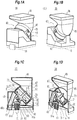
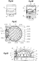
- Figs. 1A and 1B are perspective views of an external appearance of a tablet cassette 30.
- Fig. 1C is a longitudinal cross section of the tablet cassette 30 as longitudinally halved.
- Fig. 1D is a perspective view of a half portion of the longitudinally halved tablet cassette 30.
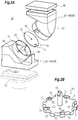
- Fig. 2A is an exploded view of the tablet cassette 30.
- Fig. 2B is a perspective view of an external appearance of a first rotor 50 mounted with a rotating shaft 62.
- the tablet cassette 30 (refer to Figs. 1 and 2A ) includes a tablet container 40 that is detachably mounted on the above-mentioned drive portion 10, the first rotor 50, the rotating shaft 62, and a second rotor 70.
- the first rotor 50, the rotating shaft 62, and a second rotor 70 are contained inside the tablet container 40.
- the first rotor 50, the rotating shaft 62, and the second rotor 70 are all together driven by means of axial rotation of the drive portion 10 when the tablet container 40 is mounted on the drive portion 10.
- the tablet cassette 30 of Embodiment 1 can be used for replacement for a conventional tablet cassette 20'.
- the tablet container 40 is common to that of the conventional tablet cassette in the following points.
- the tablet container 40 is primarily composed of a tablet containing portion located in a central position to surround a tablet receiving space (42, 47) for randomly receiving a number of tablets.
- the tablet container 40 has at its top end portion a lid 48 to be opened for replenishing the tablets.
- a bottom wall portion 41a is shaped to be mountable on an upper end of the drive portion 10 as with a lower end portion of the conventional tablet cassette 20'.
- an outlet port 43 is formed in the bottom wall portion 41a of the tablet container 40 for allowing the tablets to fall downward from the bottom wall of the tablet receiving space (42, 47).
- the tablet cassette of Embodiment 1 is, however, different from the conventional tablet cassette 20' in the following improved points.
- the tablet receiving space (42, 47) surrounded by the tablet container 40 is shaped as follows: the first rotor 50 is rotatably disposed at an inner bottom of a lower portion of the tablet receiving space (42, 47); the lower portion of the tablet receiving space (42, 47) is a cylindrical space that expands not vertically but obliquely inclined at an angle ⁇ with respect to the axial direction; the second rotor 70 is also disposed rotatably at a position obliquely upward from the first rotor 50; and at the position of the second rotor 70, the tablet receiving space (42, 47) is divided into two, a lower receiving space 42 defined between the second rotor 70 and the first rotor 50 and between the second rotor 70 and the bottom wall portion 41a, and an upper receiving space 47 defined between the second rotor 70 and the lid 48.
- the tablet container 40 is constituted from a first divided container 41 that surrounds the first rotor 50 and includes the bottom wall portion 41a, and a second divided container 45 that surrounds the second rotor 70. Since an upper end portion of the first divided container 41 can be fitted with a lower end portion of the second divided container 45, the second divided container 45 can be attached to and detached from the first divided container 41. In attaching the second divided container 45 to the first divided container 41, a projecting piece 44 of the first divided container 41 is inserted into a notch 46 of the second divided container 45 and then the second divided container 45 is turned to fix the first divided container 41 to the second divided container 45.
- a tablet guide path 49 is formed to have the outlet port 43 at one end thereof. When the first divided container 41 is mounted on the drive portion 10 of a tablet feeder, the tablet guide path 49 comes into communication with an extended tablet guide path 49a formed in the tablet feeder.
- the lower receiving space 42 works as a tablet movable space.
- the first rotor 50 (refer to Fig. 2B ) is a flat circular plate member. At the peripheral edge portion of the first rotor 50, a number of tablet receiving portions 51 (in the illustrated example, there are ten tablet receiving portions) are disposed at an equidistant interval. Here, the tablet receiving portions look like notches that have been made by cutting off the edge of the circular plate member. Since only a few tablets are scattered on the first rotor 50, each tablet receiving portion 51 is sufficient to receive one tablet and allow it to pass therefrom. There is no need of partitioning the tablets vertically stacked one on another using a partition plate. Therefore, it is not necessary to have the tablet receiving portions conform exactly to the tablet shape while partitioning is necessary for the conventional tablet receiving portions 26'. For example, when dealing with circular plate-like tablets of which the shape is employed in many other tablets, about 25% allowance in both radial and thickness directions is acceptable in the present invention.
- Protrusions 52 are provided on the upper end face of the first rotor 50 and each of the protrusions 52 is located at a position between two adjacent tablet receiving portions 51, 51 arranged in a circumferential direction and radially inward from the tablet receiving portions 51.
- the protrusions 52 are each made of a small triangular plate member.
- the protrusions 52 are provided at every other position not at each position between two adjacent tablet receiving portions 51, 51. Referring to Figs. 1 and 2A , the first rotor 50 is mounted on the top surface of the bottom wall portion 41a of the first divided container 41 of the tablet container 40.
- the first rotor 50 is contained in an inner bottom portion of the lower receiving space 42 of the tablet receiving space (42, 47) such that the first rotor 50 is axially rotated by means of rotation of the rotating shaft 62 vertically extending to pierce the inner bottom portion at the center of the inner bottom portion.
- a first gear 63 is fixed onto an end portion of the rotating shaft 62 that projects outward from the bottom wall portion 41a of the first divided container 41.
- a driven shaft 61a is rotatably supported inside the first divided container 41 and extends along a virtual vertical line passing through the first gear 63.
- a second gear 61 is fixed onto one end of the driven shaft 61a to mesh with the first gear 63.
- the rotating shaft 62 is operable to transmit a driving force generated by axial rotation of the drive portion to not only the first rotor 50 but also the second rotor 70 that is described later.
- the rotating shaft 62 is disposed such that an angle ⁇ formed by the axial line of the rotating shaft 62 and a virtual vertical line crossing the axial line is 45 degrees.
- the rotating shaft 62 extends vertically to pass through the center of the first rotor 50.
- An upper end portion of the rotating shaft 62 is inserted into a through opening 72 formed in the center of the second rotor 70 to support the second rotor 70 such that the second rotor 70 is axially rotatable.
- the rotating shaft 62 is integral with the first rotor 50, but they may be separate members to be assembled together.
- An internal gear formed by engraving from a lower end of the driven shaft 61a is operable to mesh with an external gear of the driving shaft 11 to transmit a driving force of axial rotation, as with the conventional rotating shaft 27' mentioned earlier.
- the second rotor 70 is a flat circular plate member. At the peripheral edge portion of the second rotor 70, a few through holes 71 (in the illustrated example, there is only one through hole) are formed to be opened radially outward and to allow the tablets to pass therethrough in an extending direction of the axial line of the rotating shaft 62.
- the number of the through holes 71 and the total opening area of the through holes 71 are determined such that a plurality of tablets, which have passed through the through holes 71 into the lower receiving space 42 (the tablet movable space), are prevented from becoming unable to move freely inside the lower receiving space 42.
- the second rotor 70 is disposed upward from the first rotor 50 in the tablet receiving space (42, 47), and is supported by the rotating shaft 62 extending upward from the first rotor 50 such that the second roto70 is axially rotatable, as mentioned above.
- the second rotor 70 partitions the tablet receiving space (42, 47) into upper and lower portions. Namely, the tablet receiving space (42, 47) is divided into the lower receiving space 42 and the upper receiving space 47.
- the lower receiving space 42 and the upper receiving space 47 communicate with each other via the through hole 71.
- the number of the through holes 71 formed in the second rotor 70 is smaller than the number of tablet receiving portions 51 provided at the first rotor 50. In the illustrated example, while there is one through hole 71, there are ten tablet receiving portions 51. The number of the through holes 71 is only one-tenth of the number of the tablet receiving portions 51. As with the tablet receiving portions 51, it is not necessary to have the through holes 71 conform exactly to the tablet shape, not as is necessary for the conventional tablet receiving portions 26'. More particularly, the tablets are randomly received on the second rotor 70. If there are many tablets, the tablets may stack one on another and a plurality of tablets may continuously pass through the through hole 71.
- the inclination of the second rotor 70 with respect to the horizontal line, that of the first rotor 50 with respect to the horizontal line, that of the axial line of the rotating shaft 62 with respect to the vertical line, and that of the axial centerline of a cylindrical portion of the tablet container 40 that surrounds the lower receiving space 42 with respect to the vertical line, namely, these inclinations are all made by the same angle ⁇ in the same direction.
- the inclination angle ⁇ When dealing with globular or elliptical tablets that readily roll, the inclination angle ⁇ of about 10 degrees is sufficient.
- the inclination angle is preferably larger than that.
- the inclination angle is preferably as large as about 30 - 60 degrees.
- the tablets on the first rotor 50 move rolling or slide down. If a plurality of tablets happen to get in one tablet receiving portion 51, the upper tablets of the stacked tablets in the tablet receiving portion may be caused to be surely rolled down out of the tablet receiving portion by shaking the tablets as the inclined first rotor 50 axially rotates.
- the tablet receiving portion 51 follows an arc inclination path in association with the axial rotation of the first rotor 50 and the tablets in the tablet receiving portion 51 are shaken by means of varying gravity or the like and are caused to roll down out of the tablet receiving portion 51.
- the inclination angle ⁇ is set to about 20 - 60 degrees.
- the outlet port 43 is formed at a portion of the bottom wall portion 41a of the tablet container that is directly opposed from below to one of the tablet receiving portions 51 that has moved most upward in the above-mentioned up and down movement (in the illustrated example, the highest position to which the one tablet receiving portion has reached).
- the outlet port 43 formed in the bottom wall portion 41a is positioned upward from a point of intersection of the axial line of the rotating shaft 62 and a virtual vertical line passing through the center of the outlet port 43.
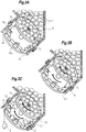
- FIGs. 3A to 3C are perspective views of the first rotor 50 and the second rotor 70 and the bottom wall portion 41a, illustrating the operating states in time series.
- tablets 4 are sequentially fed by using the tablet cassette 30. If there is a cassette 30 in which a sufficient number of tablets 4 are contained, that tablet cassette is used. If not, an available empty tablet cassette 30 should be chosen. A worker or an operator should choose an empty tablet cassette 30 that satisfies the following requirements.
- the primary requirements for choosing a tablet cassette are: one or more through holes 71 formed in the second rotor 70 and the tablet receiving portions 51 provided at the first rotor 50 should be larger in size by about 0.5 mm or by about 25% than the outer dimension of the tablet 4; and the inclination angle ⁇ of the first rotor 50 and the second rotor 70 should be about 30 to 60 degrees (in the illustrated example, about 45 degrees) suitable for circular plate-like tablets that are likely to slide down.
- the worker opens the lid 48 of the empty tablet cassette 30 and supplies a number of tablets 4, which are more than planned to use, into the upper receiving space 47 of the tablet cassette 30, and then closes the lid 48.
- replenishment of the tablets is completed and the tablet cassette 30 gets ready for use.
- most of the tablets 4 stay in the upper receiving space 47 located above the second rotor 70.
- the worker mounts the tablet cassette 30 on the drive portion 10 of an automatic dispensing apparatus such as a tablet dispensing apparatus and a tablet cutter for halving the tablets.
- an automatic dispensing apparatus such as a tablet dispensing apparatus and a tablet cutter for halving the tablets.
- the drive portion 10 and the tablet cassette 30 are operable as a tablet feeder.
- the worker sets dispensation data to a control section of the automatic dispensing apparatus such that the tablets 4 may be sequentially supplied from the tablet feeder and be sequentially fallen down and discharged.
- the dispensation data may be prepared manually or automatically based on prescription data or the like.
- the automatic dispensing apparatus gets ready for sequential supply of the tablets 4.
- the automatic dispensing apparatus is started.
- the tablet feeder is operated.
- the driving shaft 11 of the drive portion 10 axially rotates, which causes the rotating shaft 62 of the tablet cassette 30 to start axially rotating.
- the first rotor 50 and the second rotor 70 are started to axially rotate.
- the through hole 71 moves on a circular locus and comes right below one of a number of tablets 4 that are received in the upper receiving space 47. If the one tablet 4 is escaped from the constraints of other tablets, that tablet 4 passes through the through hole 71 to fall into the lower receiving space 42 (refer to Fig. 3B ).
- the tablets 4 fallen down into the lower receiving space 42 move obliquely downward, rolling or sliding on the first rotor 50 and reach the lowermost position or get in nearby tablet receiving portions 51.
- There are a number of tablet receiving portions 51 (in the illustrated example, there are as many as ten tablet receiving portions) and the tablets fallen down into the lower receiving space 42 are still few. Consequently, in most cases, the tablets 4 fallen down are likely scattered to get in different tablet receiving portions 51 one by one. Then, the tablets 4 received in the tablet receiving portions 51 are carried to the uppermost position right above the outlet port 43, following the rising part of the arc locus of the tablet receiving portions 51 as the first rotor 50 axially rotates (refer to Fig. 3C ).
- Some tablets may climb over other tablets that have already been received in the tablet receiving portions 51.
- Such tablets 4 are shaken as their attitudes in the gravity direction are varied in association with the rising movement of the tablet receiving portions 51 along the arc locus.
- Such tablets depart from the arc locus to roll or slide down onto the first rotor 50 before reaching the position right above the outlet port 43, thereby avoiding undesirable discharging of two tablets at one time.
- Such tablets undergo again the process of sequential discharging, and will be carried one by one to the position right above the outlet port 43 in due course.
- the tablet cassette 30 that no longer contains tablets may be still mounted on the automatic dispensing apparatus if it is continuously used for another prescription. If not, the tablet cassette 30 may be removed by the worker from the drive portion 10. The removed tablet cassette 30 may be kept for future use as it is. Alternatively, if it is necessary to collect the tablets 4 or the tablet cassette should be kept empty for use with other tablets, the second divided container 45 is detached from the first divided container 41 by manipulating the tablet container 40 such that the projecting piece 44 comes out of engagement with the notch 46. Then, the second rotor 70 is removed from the rotating shaft 62. Thus, the tablet cassette 30 is disassembled (refer to Fig. 2A ) for cleaning the interior of the tablet cassette. The thus cleaned tablet cassette is reassembled and kept for future use.
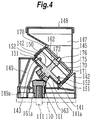
- Fig. 4 is used to explain the main part of a tablet cassette 130 according to Embodiment 2 of the present invention.
- Parts of Embodiment 2 are allocated reference numerals obtained by adding 100 to the reference numerals allocated to the counterparts of Embodiment 1 illustrated in Figs. 1 to 3 and the explanation thereof is omitted.
- the tablet cassette 130 is different from the tablet cassette 30 of Embodiment 1 in that a planetary gear mechanism 175 is provided between a second rotor 170 and a rotating shaft 162.
- Fig. 4 is a longitudinal cross section of a halved part of the tablet cassette 130.
- an upper end portion of the rotating shaft 162 is connected with the planetary gear mechanism 175, and an output shaft 176 of the planetary gear mechanism 175 is inserted into a through opening 172.
- the first rotor 150 and the second rotor 170 can rotate at different numbers of rotations.
- the number of rotations of the second rotor 170 can be used as a parameter for adjusting the number of tablets to remain or stay in the tablet movable space.
- circular tablets 4 are dealt with as a typical example.
- Regularly polygonal plate-like tablets and cylindrical capsules can be dealt with by the tablet cassette of the present invention.
- the tablet cassette of the present invention may be used for tablets of irregular shape such as a diamond plate, spindle-shaped tablets having an expanded central portion, and halved tablets prepared by cutting a complete tablet.
- the tablet cassette of the present invention may be used for other dispensing apparatuses such as a bottling machine, provided that the apparatuses are provided with a drive portion for the mountable tablet feeder.
- the tablet cassette of the present invention may also be used for semi-automated dispensing apparatuses in which the tablets are dealt with one by one in the manual operation.
Landscapes
- Physics & Mathematics (AREA)
- General Physics & Mathematics (AREA)
- Health & Medical Sciences (AREA)
- Life Sciences & Earth Sciences (AREA)
- Animal Behavior & Ethology (AREA)
- General Health & Medical Sciences (AREA)
- Public Health (AREA)
- Veterinary Medicine (AREA)
- Engineering & Computer Science (AREA)
- Mechanical Engineering (AREA)
- Medical Preparation Storing Or Oral Administration Devices (AREA)
- Basic Packing Technique (AREA)
Applications Claiming Priority (2)
| Application Number | Priority Date | Filing Date | Title |
|---|---|---|---|
| JP2015021533A JP6384835B2 (ja) | 2015-02-05 | 2015-02-05 | 錠剤カセット |
| PCT/JP2016/053358 WO2016125856A1 (fr) | 2015-02-05 | 2016-02-04 | Cartouche de comprimé |
Publications (2)
| Publication Number | Publication Date |
|---|---|
| EP3254665A1 true EP3254665A1 (fr) | 2017-12-13 |
| EP3254665A4 EP3254665A4 (fr) | 2018-10-03 |
Family
ID=56564195
Family Applications (1)
| Application Number | Title | Priority Date | Filing Date |
|---|---|---|---|
| EP16746687.9A Withdrawn EP3254665A4 (fr) | 2015-02-05 | 2016-02-04 | Cartouche de comprimé |
Country Status (5)
| Country | Link |
|---|---|
| US (1) | US20180028407A1 (fr) |
| EP (1) | EP3254665A4 (fr) |
| JP (1) | JP6384835B2 (fr) |
| CN (1) | CN107205883A (fr) |
| WO (1) | WO2016125856A1 (fr) |
Cited By (1)
| Publication number | Priority date | Publication date | Assignee | Title |
|---|---|---|---|---|
| CN110844352A (zh) * | 2019-11-13 | 2020-02-28 | 河海大学常州校区 | 一种便携式单粒出药药瓶 |
Families Citing this family (13)
| Publication number | Priority date | Publication date | Assignee | Title |
|---|---|---|---|---|
| TWI724134B (zh) * | 2016-03-25 | 2021-04-11 | 日商湯山製作所有限公司 | 片劑盒用轉子以及片劑盒 |
| US10184477B2 (en) * | 2016-12-05 | 2019-01-22 | Asia Vital Components Co., Ltd. | Series fan inclination structure |
| KR101880924B1 (ko) * | 2017-09-26 | 2018-07-23 | (주)제이브이엠 | 약제 카세트 및 이를 포함하는 약제 자동 포장기 |
| CN108113884A (zh) * | 2017-12-18 | 2018-06-05 | 无限极(中国)有限公司 | 计量装置、计量方法及三维打印机 |
| WO2019163854A1 (fr) | 2018-02-21 | 2019-08-29 | 株式会社トーショー | Cassette de comprimés |
| JP7081799B2 (ja) * | 2018-04-25 | 2022-06-07 | 株式会社トーショー | 錠剤供給装置及び薬剤払出し装置 |
| EP3594147B1 (fr) * | 2018-07-11 | 2021-08-11 | Industrias Plasticas Triana S.A. | Dispositif de dosage unitaire de comprimés ou de pilules |
| CN109166248A (zh) * | 2018-09-07 | 2019-01-08 | 上海市普陀区曹杨街道社区卫生服务中心(上海市普陀区曹杨红十字地段医院) | 一种药房发药系统 |
| JP7479037B2 (ja) * | 2019-02-04 | 2024-05-08 | 株式会社タカゾノ | 薬剤供給装置 |
| EP4115870A4 (fr) * | 2020-03-03 | 2024-03-13 | Tosho, Inc. | Cassette de comprimés |
| US11354968B2 (en) | 2020-03-05 | 2022-06-07 | Troy G. Anderson, M.D., P.C. | Pill storage and dispensing systems and methods |
| US11498761B1 (en) * | 2021-06-22 | 2022-11-15 | Vmi Holland B.V. | Method for dispensing discrete medicaments, a test station for testing a feeder unit, and a method for determining a fill level of a feeder unit |
| US20230210724A1 (en) * | 2022-01-06 | 2023-07-06 | Anthony J. Guarascio | Portable electronic pill dispenser with replaceable insert |
Family Cites Families (41)
| Publication number | Priority date | Publication date | Assignee | Title |
|---|---|---|---|---|
| US2176232A (en) * | 1937-10-16 | 1939-10-17 | Morton Salt Co | Dispensing device for tablets, lozenges, pellets, and the like |
| US2243335A (en) * | 1939-06-26 | 1941-05-27 | Hamilton Entpr Inc | Vending machine |
| US2750072A (en) * | 1951-01-25 | 1956-06-12 | Duncan Edith Baldwin | Devices for containing and dispensing granular, powdered or crystalline material |
| US2748914A (en) * | 1954-01-14 | 1956-06-05 | William E Shields Jr | Article orienting means |
| US2898010A (en) * | 1955-07-13 | 1959-08-04 | Tepper Solomon | Measuring and dispensing device |
| US2877937A (en) * | 1957-11-01 | 1959-03-17 | Gordon E Weir | Measuring dispenser |
| US3211334A (en) * | 1963-12-23 | 1965-10-12 | Terrance J Mcshea | Variable charge coffee dispenser |
| US3246806A (en) * | 1964-09-02 | 1966-04-19 | Jr Charles L Mcbride | Planter |
| US3269612A (en) * | 1964-12-31 | 1966-08-30 | Russell O Brien | Measuring and dispensing device |
| US3308995A (en) * | 1965-06-01 | 1967-03-14 | Robert W Lee | Dispensing device |
| US3785525A (en) * | 1972-01-31 | 1974-01-15 | Safe Well Mfg Co | Chemical tablet dispensing device for wells |
| US3991908A (en) * | 1975-06-27 | 1976-11-16 | Ryder International Corporation | Pill dispenser |
| US4207857A (en) * | 1978-05-18 | 1980-06-17 | Balka William J Jr | Automatic ball server |
| US4273254A (en) * | 1979-01-23 | 1981-06-16 | Brian Cuppleditch | Device for containing and dispensing particles such as tablets |
| US4485938A (en) * | 1983-03-21 | 1984-12-04 | Williams Marvin D | Tamperproof pill dispensing apparatus |
| US5017176A (en) * | 1990-01-25 | 1991-05-21 | Dixiw-Narco, Inc. | Coin hopper and dispenser |
| US5097985A (en) * | 1990-05-31 | 1992-03-24 | Jones Kenneth E | Baseball soft-toss pitching machine and method |
| JP2944234B2 (ja) * | 1991-03-06 | 1999-08-30 | 三洋電機株式会社 | 薬剤供給装置 |
| JP3487647B2 (ja) * | 1993-11-11 | 2004-01-19 | 株式会社エヌテック | 粉粒体の定量排出器 |
| JP3524606B2 (ja) * | 1994-12-28 | 2004-05-10 | 三洋電機株式会社 | 固形製剤充填装置 |
| US5954229A (en) * | 1997-10-16 | 1999-09-21 | Moldex-Metric, Inc | Wall mounted earplug dispenser |
| JP2002154637A (ja) * | 2000-11-20 | 2002-05-28 | Tosho Inc | 薬剤フィーダ |
| US6497342B2 (en) * | 2000-11-30 | 2002-12-24 | Mckesson Automated Healthcare, Inc. | Medicine feeder |
| US6550640B2 (en) * | 2001-03-12 | 2003-04-22 | William G. Smith | Method and apparatus for controllably dispensing powders and liquids |
| KR20030040747A (ko) * | 2001-11-15 | 2003-05-23 | 김용태 | 수동식 정제 의약품분배기 |
| US6918509B2 (en) * | 2002-04-24 | 2005-07-19 | Mars Incorporated | Toy and pogo dispenser |
| KR200334608Y1 (ko) * | 2003-07-16 | 2003-12-01 | 주식회사 일영무역 | 수납통 |
| US6991131B2 (en) * | 2003-09-02 | 2006-01-31 | Ecolab, Inc. | Distributable container and system and method using distributable container |
| JP4473174B2 (ja) * | 2005-05-09 | 2010-06-02 | 高園産業株式会社 | 錠剤カセッタ |
| US7743942B1 (en) * | 2006-08-11 | 2010-06-29 | Kil Jae Chang | Dispensing wheel alignment devices in vending machine |
| US7992748B2 (en) * | 2006-11-17 | 2011-08-09 | North Safety Products, Inc. | Earplug dispenser |
| JP4394697B2 (ja) * | 2007-03-02 | 2010-01-06 | 高園産業株式会社 | 薬剤カセッター |
| JP5473622B2 (ja) * | 2010-01-15 | 2014-04-16 | 株式会社トーショー | 錠剤フィーダ |
| JP5473882B2 (ja) * | 2010-12-09 | 2014-04-16 | 株式会社トーショー | 薬剤フィーダ |
| CN102579255B (zh) * | 2012-02-23 | 2014-03-19 | 三二〇一医院 | 一种具备多种计数及面向不同大小药粒定量出药功能的药瓶 |
| TW201414649A (zh) * | 2012-10-09 | 2014-04-16 | Hon Hai Prec Ind Co Ltd | 藥丸存取裝置 |
| KR101449717B1 (ko) * | 2013-01-02 | 2014-10-15 | 주식회사 인포피아 | 약제 포장장치용 정제 카트리지 |
| KR101511263B1 (ko) * | 2013-01-23 | 2015-04-13 | 주식회사 인포피아 | 롤링 회전되는 드럼이 내장된 약제 포장 장치용 카트리지 |
| JP5509371B2 (ja) * | 2013-05-23 | 2014-06-04 | 株式会社タカゾノ | 錠剤カセッタ |
| JP6000195B2 (ja) * | 2013-07-03 | 2016-09-28 | 株式会社トーショー | 錠剤カセット |
| US9501890B2 (en) * | 2013-12-23 | 2016-11-22 | 3M Innovative Properties Company | Reduced friction earplug dispenser |
-
2015
- 2015-02-05 JP JP2015021533A patent/JP6384835B2/ja active Active
-
2016
- 2016-02-04 WO PCT/JP2016/053358 patent/WO2016125856A1/fr not_active Ceased
- 2016-02-04 CN CN201680008752.XA patent/CN107205883A/zh active Pending
- 2016-02-04 US US15/548,234 patent/US20180028407A1/en not_active Abandoned
- 2016-02-04 EP EP16746687.9A patent/EP3254665A4/fr not_active Withdrawn
Cited By (1)
| Publication number | Priority date | Publication date | Assignee | Title |
|---|---|---|---|---|
| CN110844352A (zh) * | 2019-11-13 | 2020-02-28 | 河海大学常州校区 | 一种便携式单粒出药药瓶 |
Also Published As
| Publication number | Publication date |
|---|---|
| WO2016125856A1 (fr) | 2016-08-11 |
| US20180028407A1 (en) | 2018-02-01 |
| JP2016140724A (ja) | 2016-08-08 |
| JP6384835B2 (ja) | 2018-09-05 |
| EP3254665A4 (fr) | 2018-10-03 |
| CN107205883A (zh) | 2017-09-26 |
Similar Documents
| Publication | Publication Date | Title |
|---|---|---|
| EP3254665A1 (fr) | Cartouche de comprimé | |
| EP3017805B1 (fr) | Cassette de comprimés pour distributeur de comprimés | |
| US10486889B2 (en) | Drug feeder | |
| EP2664316B1 (fr) | Cassette de cachets | |
| JP6894384B2 (ja) | 自動薬剤調合装置のための薬剤供給キャニスタ | |
| US6471093B1 (en) | Tablet feeder | |
| EP1285850A2 (fr) | Distributeur de comprimés | |
| JP6590341B2 (ja) | 薬剤フィーダ及び錠剤分割装置 | |
| KR20130139865A (ko) | 약제 송출 장치 및 약제 계수 장치 | |
| WO2018128133A1 (fr) | Dispositif d'alimentation en médicament | |
| US11759398B2 (en) | Medicine case and medicine supply device | |
| CN113260588B (zh) | 锭剂盒用转动件和锭剂盒 | |
| JP6914489B2 (ja) | 錠剤カセット | |
| JP6918327B2 (ja) | 錠剤カセット | |
| JP7539147B2 (ja) | 分離送出装置、計数充填装置及び被計数材料の分離送出方法 | |
| JP6901104B2 (ja) | 錠剤カセット | |
| WO2018021412A1 (fr) | Cassette de comprimés pour distributeur de comprimés | |
| US20250178767A1 (en) | Drug feeder and tablet packing machine | |
| JP2007197136A (ja) | カップ供給装置 | |
| WO2017198318A1 (fr) | Rotor flexible destiné à être utilisé dans une boîte, et procédé de fabrication d'un tel rotor | |
| EP3973940A1 (fr) | Cassette de comprimés |
Legal Events
| Date | Code | Title | Description |
|---|---|---|---|
| STAA | Information on the status of an ep patent application or granted ep patent |
Free format text: STATUS: THE INTERNATIONAL PUBLICATION HAS BEEN MADE |
|
| PUAI | Public reference made under article 153(3) epc to a published international application that has entered the european phase |
Free format text: ORIGINAL CODE: 0009012 |
|
| STAA | Information on the status of an ep patent application or granted ep patent |
Free format text: STATUS: REQUEST FOR EXAMINATION WAS MADE |
|
| 17P | Request for examination filed |
Effective date: 20170905 |
|
| AK | Designated contracting states |
Kind code of ref document: A1 Designated state(s): AL AT BE BG CH CY CZ DE DK EE ES FI FR GB GR HR HU IE IS IT LI LT LU LV MC MK MT NL NO PL PT RO RS SE SI SK SM TR |
|
| AX | Request for extension of the european patent |
Extension state: BA ME |
|
| DAV | Request for validation of the european patent (deleted) | ||
| DAX | Request for extension of the european patent (deleted) | ||
| A4 | Supplementary search report drawn up and despatched |
Effective date: 20180830 |
|
| RIC1 | Information provided on ipc code assigned before grant |
Ipc: A61J 7/00 20060101ALI20180824BHEP Ipc: B65D 83/04 20060101ALI20180824BHEP Ipc: G07F 11/00 20060101AFI20180824BHEP |
|
| GRAP | Despatch of communication of intention to grant a patent |
Free format text: ORIGINAL CODE: EPIDOSNIGR1 |
|
| STAA | Information on the status of an ep patent application or granted ep patent |
Free format text: STATUS: GRANT OF PATENT IS INTENDED |
|
| INTG | Intention to grant announced |
Effective date: 20191111 |
|
| STAA | Information on the status of an ep patent application or granted ep patent |
Free format text: STATUS: THE APPLICATION IS DEEMED TO BE WITHDRAWN |
|
| 18D | Application deemed to be withdrawn |
Effective date: 20200603 |