EP3254752A1 - Corps de remplissage - Google Patents
Corps de remplissage Download PDFInfo
- Publication number
- EP3254752A1 EP3254752A1 EP16173501.4A EP16173501A EP3254752A1 EP 3254752 A1 EP3254752 A1 EP 3254752A1 EP 16173501 A EP16173501 A EP 16173501A EP 3254752 A1 EP3254752 A1 EP 3254752A1
- Authority
- EP
- European Patent Office
- Prior art keywords
- inner guide
- packing
- guide profile
- main expansion
- outer structure
- Prior art date
- Legal status (The legal status is an assumption and is not a legal conclusion. Google has not performed a legal analysis and makes no representation as to the accuracy of the status listed.)
- Withdrawn
Links
- 238000011049 filling Methods 0.000 title claims abstract description 49
- 239000000945 filler Substances 0.000 claims abstract description 45
- 239000007788 liquid Substances 0.000 claims abstract description 6
- 238000012856 packing Methods 0.000 claims description 41
- 239000000463 material Substances 0.000 claims description 3
- 239000000919 ceramic Substances 0.000 claims description 2
- 239000002184 metal Substances 0.000 claims description 2
- 239000004033 plastic Substances 0.000 claims description 2
- 239000012530 fluid Substances 0.000 description 16
- 238000002156 mixing Methods 0.000 description 6
- 238000012546 transfer Methods 0.000 description 5
- 238000013461 design Methods 0.000 description 4
- 238000000034 method Methods 0.000 description 4
- 238000011161 development Methods 0.000 description 3
- 238000000926 separation method Methods 0.000 description 3
- 230000000694 effects Effects 0.000 description 2
- 238000004519 manufacturing process Methods 0.000 description 2
- 238000012986 modification Methods 0.000 description 2
- 230000004048 modification Effects 0.000 description 2
- 239000000126 substance Substances 0.000 description 2
- 238000010146 3D printing Methods 0.000 description 1
- 238000010521 absorption reaction Methods 0.000 description 1
- 239000000443 aerosol Substances 0.000 description 1
- 230000015572 biosynthetic process Effects 0.000 description 1
- 210000001124 body fluid Anatomy 0.000 description 1
- 239000010839 body fluid Substances 0.000 description 1
- 230000003197 catalytic effect Effects 0.000 description 1
- 238000006243 chemical reaction Methods 0.000 description 1
- 238000002485 combustion reaction Methods 0.000 description 1
- 238000001816 cooling Methods 0.000 description 1
- 230000008021 deposition Effects 0.000 description 1
- 238000003795 desorption Methods 0.000 description 1
- 238000004821 distillation Methods 0.000 description 1
- 238000000605 extraction Methods 0.000 description 1
- 230000035515 penetration Effects 0.000 description 1
- 230000005501 phase interface Effects 0.000 description 1
- 230000001172 regenerating effect Effects 0.000 description 1
- 230000007704 transition Effects 0.000 description 1
Images






Classifications
-
- B—PERFORMING OPERATIONS; TRANSPORTING
- B01—PHYSICAL OR CHEMICAL PROCESSES OR APPARATUS IN GENERAL
- B01J—CHEMICAL OR PHYSICAL PROCESSES, e.g. CATALYSIS OR COLLOID CHEMISTRY; THEIR RELEVANT APPARATUS
- B01J19/00—Chemical, physical or physico-chemical processes in general; Their relevant apparatus
- B01J19/30—Loose or shaped packing elements, e.g. Raschig rings or Berl saddles, for pouring into the apparatus for mass or heat transfer
-
- B—PERFORMING OPERATIONS; TRANSPORTING
- B01—PHYSICAL OR CHEMICAL PROCESSES OR APPARATUS IN GENERAL
- B01J—CHEMICAL OR PHYSICAL PROCESSES, e.g. CATALYSIS OR COLLOID CHEMISTRY; THEIR RELEVANT APPARATUS
- B01J2219/00—Chemical, physical or physico-chemical processes in general; Their relevant apparatus
- B01J2219/30—Details relating to random packing elements
- B01J2219/302—Basic shape of the elements
- B01J2219/30203—Saddle
-
- B—PERFORMING OPERATIONS; TRANSPORTING
- B01—PHYSICAL OR CHEMICAL PROCESSES OR APPARATUS IN GENERAL
- B01J—CHEMICAL OR PHYSICAL PROCESSES, e.g. CATALYSIS OR COLLOID CHEMISTRY; THEIR RELEVANT APPARATUS
- B01J2219/00—Chemical, physical or physico-chemical processes in general; Their relevant apparatus
- B01J2219/30—Details relating to random packing elements
- B01J2219/302—Basic shape of the elements
- B01J2219/3023—Triangle
- B01J2219/30234—Hexagon
-
- B—PERFORMING OPERATIONS; TRANSPORTING
- B01—PHYSICAL OR CHEMICAL PROCESSES OR APPARATUS IN GENERAL
- B01J—CHEMICAL OR PHYSICAL PROCESSES, e.g. CATALYSIS OR COLLOID CHEMISTRY; THEIR RELEVANT APPARATUS
- B01J2219/00—Chemical, physical or physico-chemical processes in general; Their relevant apparatus
- B01J2219/30—Details relating to random packing elements
- B01J2219/302—Basic shape of the elements
- B01J2219/30242—Star
-
- B—PERFORMING OPERATIONS; TRANSPORTING
- B01—PHYSICAL OR CHEMICAL PROCESSES OR APPARATUS IN GENERAL
- B01J—CHEMICAL OR PHYSICAL PROCESSES, e.g. CATALYSIS OR COLLOID CHEMISTRY; THEIR RELEVANT APPARATUS
- B01J2219/00—Chemical, physical or physico-chemical processes in general; Their relevant apparatus
- B01J2219/30—Details relating to random packing elements
- B01J2219/302—Basic shape of the elements
- B01J2219/30246—Square or square-derived
-
- B—PERFORMING OPERATIONS; TRANSPORTING
- B01—PHYSICAL OR CHEMICAL PROCESSES OR APPARATUS IN GENERAL
- B01J—CHEMICAL OR PHYSICAL PROCESSES, e.g. CATALYSIS OR COLLOID CHEMISTRY; THEIR RELEVANT APPARATUS
- B01J2219/00—Chemical, physical or physico-chemical processes in general; Their relevant apparatus
- B01J2219/30—Details relating to random packing elements
- B01J2219/302—Basic shape of the elements
- B01J2219/30296—Other shapes
-
- B—PERFORMING OPERATIONS; TRANSPORTING
- B01—PHYSICAL OR CHEMICAL PROCESSES OR APPARATUS IN GENERAL
- B01J—CHEMICAL OR PHYSICAL PROCESSES, e.g. CATALYSIS OR COLLOID CHEMISTRY; THEIR RELEVANT APPARATUS
- B01J2219/00—Chemical, physical or physico-chemical processes in general; Their relevant apparatus
- B01J2219/30—Details relating to random packing elements
- B01J2219/304—Composition or microstructure of the elements
- B01J2219/30416—Ceramic
-
- B—PERFORMING OPERATIONS; TRANSPORTING
- B01—PHYSICAL OR CHEMICAL PROCESSES OR APPARATUS IN GENERAL
- B01J—CHEMICAL OR PHYSICAL PROCESSES, e.g. CATALYSIS OR COLLOID CHEMISTRY; THEIR RELEVANT APPARATUS
- B01J2219/00—Chemical, physical or physico-chemical processes in general; Their relevant apparatus
- B01J2219/30—Details relating to random packing elements
- B01J2219/304—Composition or microstructure of the elements
- B01J2219/30466—Plastics
Definitions
- the invention relates to a packing, in particular for mass and / or heat exchange columns, which are penetrated by a gas and / or liquid flow, comprising an outer structure, wherein formed by the outer structure, two opposite main expansion surfaces of the packing, and having one between the two Main expansion surfaces trained interior structure.
- the fillers enlarge the surface in the volume filled by them and thereby intensify the mass or heat exchange between the different phases or media within this volume.
- the phase interface for the mass transfer usually does not match exactly with the geometric Instead, it is the sum of the filler surface wetted during the process and the sum of the surface area of all the droplets forming in the packed bed and / or forming rivulets.
- fillers or random packings serve for the separation of small and very small liquid droplets up to the deposition of so-called aerosols. Fillers are also used as a growth surface for a biofilm in biological systems and as a trickling filter in scrubbers.
- the packed bed formed by the packing has a certain pressure loss compared with the flow of the phases. This depends on the gas load factor, the sprinkling density, the type of filler, the size of the filler, the geometric shape of the filler and other parameters.
- the packings must have suitable mechanical stability and surface area for all applications, as well as good mixing of the various phases or media without, however, counteracting the flow of the phases or media to excessive pressure loss.
- the bulk volume required for the respective separation process or chemical or thermal process should be as low as possible.
- a filler having the features of the preamble of claim 1 is known from the document EP 1 586 375 A1 known.
- This filler body has two main expansion surfaces facing away from each other, an outer structure and an inner structure, wherein the outer structure encloses the inner structure.
- the inner structure is latticed and has at least two passageways. Furthermore, a cross section of the outer structure is formed with at least six edges.
- Object of the present invention is to develop a filler with two opposite main expansion surfaces and an outer structure and an inner structure such that it is characterized by an optimum in terms of low pressure loss and suitably large area. Furthermore, a particularly good mixing of media, which flow through the filler body or a packed bed formed by this filler body, is to be achieved, so that a particularly large mass transfer or heat exchange results.
- the filler body has an outer structure and an inner structure, two main expansion surfaces of the filler body facing away from one another being formed by the outer structure, and the structure of the filler body formed between the two main expansion surfaces forming the inner structure.
- the inner structure has at least one inner guide profile, wherein the inner guide profile is formed inclined to the main expansion surfaces.
- inclined is to be understood to mean that the inner guide profile is formed neither perpendicular nor parallel to the main expansion surfaces.
- the inner guide profile formed between the two main expansion surfaces causes a fluid flowing into the filling body, in particular a fluid flowing from one main expansion surface in the direction of the other main expansion surface, to be deflected within the filling body through the inner guide profile.
- a fluid flowing into the filling body in particular a fluid flowing from one main expansion surface in the direction of the other main expansion surface
- the flow velocity and the flow direction of the fluid flowing through the filler are changed, whereby a particularly good mixing, in particular a turbulence is achieved, which in turn has an advantageous effect on the mass and / or heat exchange.
- this will also be predominantly flat in a bed, for example in a column, ie the Surface normal of one of the two partial surfaces of one of the two of the main expansion surfaces or of a plane formed by the outer structure will usually be approximately parallel to the column axis. This also has an advantageous effect on the mass and / or heat exchange.
- the inner guide profile is designed plate-shaped with a preferably small wall thickness, wherein it is quite conceivable that the inner guide profile is curved.
- a plane is formed on the side of the filler body having a main expansion surface by the outer structure, wherein the inner guide profile is formed inclined to this plane.
- a small angle between the inner guide profile and the plane corresponds to a particularly strong deflection of a fluid flowing in the direction of the one main expansion surface.
- the angle between the inner guide profile and the plane is preferably ⁇ 10 ° to ⁇ 80 °, in particular ⁇ 20 ° to ⁇ 70 °.
- a small angle for example in the range of 20 °, represents a very flat embodiment of the filling body and thus a filler with a low overall height but with a higher pressure loss.
- a filler with a guide profile in the angular range of 70 ° has a correspondingly greater overall height and is characterized by a lower pressure drop for the fluid flow.
- the filler body has a plurality of spaced inner guide profiles, wherein it is provided in particular that the inner guide profiles are formed inclined in the same direction.
- the design of the filler body with several inner guide profiles ensures that a particularly effective deflection the fluid flow within the packing is achieved over the largest possible area with a simultaneously low overall height of the packing.
- adjacent inner guide profiles are inclined relative to one another and thus not parallel to one another. This causes a fluid flow entering the guide body to be deflected at different angles on the different guide profiles, whereby the speed and direction of the fluid flow are local can be varied, making the mass and / or mass exchange more efficient.
- An angle between two inner guide profiles is preferably between 5 ° and 20 °.
- two adjacent inner guide profiles form a passageway passing through the filler body from the one main expansion surface in the direction of the other main expansion surface.
- a liquid flowing in or falling down in the direction of the plane onto the filling body only encounters surfaces of the inner guide profiles facing the inflow direction, wherein overlapping partial regions of the inner guide profiles and surfaces of the inner guide profiles facing away from the inflow direction remain dry.
- An inflowing to the opposite surface of the guide gas flow can be undisturbed deflected at the guide profiles and in the intermediate region between the guide profiles. This results in a low pressure loss.
- holes, slots or other opening forms can be introduced into the guide profiles, whereby liquid also reaches the back of the respective guide profile and an intensive mixing of the various fluids takes place, so that the mass transfer or heat exchange is increased.
- the inner structure has at least one connecting web, wherein the connecting web the inner guide profile with the outer structure or two inner guide profiles connects.
- the connecting web is preferably thin-walled in order to ensure a low flow resistance and a low weight of the filling body.
- This connecting web can be completely or partially in the inner structure. It is also conceivable that the connecting web on the very outside on one of the two main expansion surfaces -. connecting over the outer guide profiles and over the outer structure - is attached.
- the filler body has at least one outer guide profile, wherein the outer guide profile of one of the main expansion surfaces and / or formed by an external structure, between the main expansion surfaces arranged side surface of the packing is formed outwardly projecting.
- the inner guide profile and the outer guide profile portions of a guide body passes through at least one of the main expansion surfaces and / or at least one of the side surfaces of the filler.
- an inner guide profile and an outer guide profile, a guide body and an inner Guide profile and / or a plurality of guide bodies are arranged in a direction perpendicular to the plane formed by the outer structure overlapping.
- the inner and / or outer guide profile has at least one passage opening. Through the passage opening of the flow resistance of the packing is reduced and also varies the flow profile of the incoming fluid locally.
- the passage opening may be formed, for example, circular or slot-like. It is also conceivable that a plurality of cuts are made in the guide profile, wherein a passage opening is formed by a bow lying between the cuts portion of the Leitprofils is bent, in particular two adjacent portions are bent in opposite directions bow-shaped.
- the inner and / or the outer guide profile more, preferably in the direction of the one main expansion surface and / or in the direction of the other main expansion surface having formed projections.
- these projections are rod-shaped, wherein it is quite conceivable that a projection passes through the main expansion surface facing it.
- the filling body has at least one passage opening in at least one of the side surfaces. It is considered particularly advantageous if two side faces of the outer structure facing away from one another each have at least one passage opening.
- the outer structure is preferably flat and / or corrugated and / or angled and / or designed saddle-shaped and / or twisted.
- the outer structure has two side faces facing away from one another, wherein these side faces can be angled relative to each other.
- a cross section of the outer structure is formed, which has a plurality of outwardly directed edges. These edges are in particular pointed.
- the outer structure of the filler body in opposite end regions is formed stronger or weaker than in a central region of the outer structure, which is located between the opposite end portions.
- the filler body between the respective end region and the central region is formed stronger or weaker than in the end region and in the central region.
- surfaces of the filler in particular the surface of the inner guide profile, at least partially profiled designed.
- the filler is in particular made of plastic or metal or ceramic. These materials make it possible to make the structures of the packing, in particular the inner guide profile, the outer guide profile, the guide body, the connecting web and the outer structure as possible, so that a very open structure of the packing and the lowest possible weight of the packing with yet high mechanical Stability is guaranteed.
- 3D printing is also modern production methods - such. 3D printing - considered for the different materials.
- the respective illustrated in the figures embodiment of the filling body 1 is found with a plurality of corresponding filler 1 use in an arrangement in a so-called.
- Bed of packing usually a random bed.
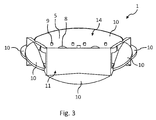
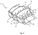
- the in the Fig. 1 to 6 illustrated design of a first embodiment of the filling body 1 has an outer structure 2 with two mutually remote main expansion surfaces 3, 4, wherein a cross section of the outer structure 2 is formed, which has six outwardly directed edges 13.
- the filling body 1 has a plurality of side surfaces 11, wherein these side surfaces 11 are formed between the two main expansion surfaces 3, 4.
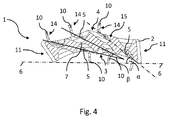
- An inner structure 15 formed between the two main expansion surfaces 3, 4 has three inner guide profiles 5, these inner guide profiles 5 being inclined relative to the main expansion surfaces 3, 4.
- the inner guide profiles 5 are arranged inclined in the same direction, wherein adjacent inner guide profiles 5 are not parallel to each other, but inclined to each other.
- An angle ⁇ between two inner guide profiles 5 is preferably between 5 ° and 20 °, in particular between 10 ° and 15 °.
- a plane 6 is formed by the outer structure 2.
- the inner guide profiles 5 are inclined to this plane 6, wherein an angle ⁇ between one of the inner Guide profiles 5 and this level 6 is between 10 ° and 70 °, in particular the Fig. 4 can be seen.
- the inner guide profiles 5 are preferably thin-walled and preferably slightly curved, wherein a turning point for the curvature may be present.
- the inner structure 15 of the filling body 1 has four, arranged in a plane perpendicular to the plane 6 other connecting webs 7, wherein two of these connecting webs 7 each two adjacent inner guide profiles 5 interconnects and the remaining two connecting webs 7 each an inner guide profile 5 with the outer structure 2 connects.
- the outer structure 2 of the filling body 1 is substantially flat and / or slightly curved.
- the main expansion surfaces 3, 4 each have two concave partial surfaces.
- the filler body 1 has twelve outwardly projecting outer guide profiles 10. Six of these twelve outer guide profiles 10 are formed on opposite side surfaces 11. These formed on the side surfaces 11 outer guide profiles 10 are particularly in the Fig. 2 to recognize.
- the other six outer guide profiles 10 are formed on the main expansion surfaces 3, 4, wherein three outer guide profiles 10 are formed on the one main expansion surface 3 and three other outer guide profiles 10 on the other main expansion surface 4, in particular the Fig. 1 refer to.
- the guide body 14 passes through the two main expansion surfaces 3, 4 and two opposite side surfaces 11 of the filling body.
- the guide body 14 In a cross section perpendicular to the two main expansion surfaces 3, 4, the guide body 14 has an S-shaped cross-section.
- the inner guide profiles 5 each have a plurality of circular passage openings 8 and a plurality of rod-shaped projections 9 formed in the direction of the other main expansion surface 4.
- the passage openings 8 serve to reduce the pressure loss at the guide body 1 and also a mixing and turbulence of the guide body 1 flowing through the fluid.
- the rod-shaped projections 9 on the surface of the inner guide profile 5 function u.a. as additional drip points.
- a particularly open structure of the filling body 1 is achieved in that two opposite side surfaces 11 of the filling body 1 each have two passage openings 12.
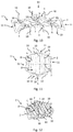
- Fig. 7 to 9 show a second embodiment of the filling body 1, this embodiment of the first embodiment substantially differs in that the inner guide profile 5 is formed substantially smooth and closed and thus free of projections 9 and openings 8 and adjacent guide profiles 5 in the overhead projection not overlap.
- the inner guide profiles 5 are formed flat, whereas the outer guide profiles 10 are formed bent, wherein the outer guide profile 10 approximately tangentially to the one main expansion surface 3 and approximately perpendicular to the other main expansion surface 4 connects.
- third embodiment differs from that in the Fig. 7 to 9 shown embodiment essentially in that the inner guide profiles 5 each have a plurality of slot-like passage openings 8.
- Fig. 13 to 15 embodiment shown is distinguished from the previous embodiment in that the slot-like openings 8 are formed by the fact that in the inner guide sections 5 more cuts are made, lying between the cuts portions of the inner guide profile 5 are bent in the opposite direction bow-shaped.
- the inner guide profiles 5 have a plurality of rod-shaped projections 9, wherein both the one of the main expansion surface 3 side facing as well as the other main expansion surface 4 facing side of the inner guide profile 5 with Projections 9 is provided.
- the rod-shaped projections 9 are designed approximately identical.
- the longitudinal extent of the projections 9 is such that a part of the projections 9 passes through the one main expansion surface 3 or the other main expansion surface 4 or at least approximately touched.
- the embodiment can also be designed without the outer guide profiles.
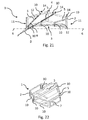
- the Fig. 19 to 22nd show a sixth embodiment of the filling body 1, this embodiment of the first embodiment essentially differs in that the inner guide profile 5 is formed substantially smooth and closed and thus free of projections 9 and openings 8 and adjacent guide profiles 5 in the overhead projection not overlap.
- the transitions between the guide profiles 5 and the outer guide profiles 10 are not rounded, but angular.
- the inner guide profiles 5 and outer guide profiles 10 are formed as rectangular plates. External guide profiles 10 on the side surfaces are not present.
- the connecting web 7 sits on the outside of the outer structure 2, at least on the outer guide profiles 10 of at least one of the main expansion surface (3 or 4). But it is also conceivable without a connecting bar to get along.
- All side surfaces of the outer structure 2 - ie all side surfaces perpendicular to the plane 6 formed - have at least one passage opening for a fluid flow. But it is also possible that only a part of these side surfaces has such a passage opening to the point that none of these side surfaces has such a passage opening.
- Opposing side surfaces ie, the first and fourth in a count order left or right - regardless of which of the side surfaces is selected as the first
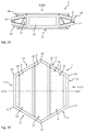
- FIGS. 23 to 26 show a seventh embodiment of the filling body 1, wherein this embodiment differs from the sixth embodiment in that the adjacent to the end faces of the guide profiles 5 four side surfaces 11 of the outer structure 2 of the filling body 1 are each not rectangular, but the one side surface 11 to adjacent side surface 11 tapered conically, so that the respective side surface has a trapezoidal shape.
- the outer structure 2 is formed in the opposite end portions of the remaining two parallel side surfaces 11 stronger than in the central region of the outer structure, in which the relevant two side surfaces abut each other. With slight modification of the outer structure 2 in the region of the two adjoining said side surfaces 11, the outer structure 2 could be modified such that it is made stronger in the opposite end regions than in the middle region.
- the trapezoid does not taper to the connecting portion of these two sides 11, as shown in this seventh embodiment, but expands.
- Another modification is by changing the shape of the diverging rods of each Trapezes possible.
- the bars of the trapezoid are straight. They may well be curved, in particular from the output trapezoidal plane, with respect to this bent outwards or inwards. This makes it possible to represent a filling body 1 which is formed stronger or weaker between the respective end region and the middle region than in the end region and in the middle region.
Landscapes
- Chemical & Material Sciences (AREA)
- Physics & Mathematics (AREA)
- Thermal Sciences (AREA)
- Organic Chemistry (AREA)
- Chemical Kinetics & Catalysis (AREA)
- Physical Or Chemical Processes And Apparatus (AREA)
Priority Applications (2)
| Application Number | Priority Date | Filing Date | Title |
|---|---|---|---|
| EP16173501.4A EP3254752A1 (fr) | 2016-06-08 | 2016-06-08 | Corps de remplissage |
| EP17173612.7A EP3254754B1 (fr) | 2016-06-08 | 2017-05-31 | Corps de remplissage |
Applications Claiming Priority (1)
| Application Number | Priority Date | Filing Date | Title |
|---|---|---|---|
| EP16173501.4A EP3254752A1 (fr) | 2016-06-08 | 2016-06-08 | Corps de remplissage |
Publications (1)
| Publication Number | Publication Date |
|---|---|
| EP3254752A1 true EP3254752A1 (fr) | 2017-12-13 |
Family
ID=56134131
Family Applications (2)
| Application Number | Title | Priority Date | Filing Date |
|---|---|---|---|
| EP16173501.4A Withdrawn EP3254752A1 (fr) | 2016-06-08 | 2016-06-08 | Corps de remplissage |
| EP17173612.7A Active EP3254754B1 (fr) | 2016-06-08 | 2017-05-31 | Corps de remplissage |
Family Applications After (1)
| Application Number | Title | Priority Date | Filing Date |
|---|---|---|---|
| EP17173612.7A Active EP3254754B1 (fr) | 2016-06-08 | 2017-05-31 | Corps de remplissage |
Country Status (1)
| Country | Link |
|---|---|
| EP (2) | EP3254752A1 (fr) |
Families Citing this family (1)
| Publication number | Priority date | Publication date | Assignee | Title |
|---|---|---|---|---|
| US12303859B2 (en) | 2019-08-27 | 2025-05-20 | Sabic Global Technologies B.V. | Mass transfer swirler including distribution member |
Citations (6)
| Publication number | Priority date | Publication date | Assignee | Title |
|---|---|---|---|---|
| GB1498360A (en) * | 1975-05-21 | 1978-01-18 | Norton Co | Packing elements for biological trickle filters |
| WO1984002088A1 (fr) * | 1982-11-29 | 1984-06-07 | Merix Corp | Unite d'emballage |
| EP0930096A2 (fr) * | 1998-01-19 | 1999-07-21 | Air Products And Chemicals, Inc. | Garnissage structuré horizontale |
| EP1586375A1 (fr) | 2004-03-15 | 2005-10-19 | Vereinigte Füllkörper-Fabriken GmbH & Co. KG | Elément de remplissage |
| WO2011149802A2 (fr) * | 2010-05-26 | 2011-12-01 | Saint-Gobain Ceramics & Plastics, Inc. | Élément de conditionnement pour le transfert de masse et son procédé de fabrication |
| DE102013018190A1 (de) * | 2013-10-30 | 2015-04-30 | Raschig Gmbh | Füllkörper, insbesondere für Stoff- und/oder Wärmeaustauschkolonnen oder -türme |
-
2016
- 2016-06-08 EP EP16173501.4A patent/EP3254752A1/fr not_active Withdrawn
-
2017
- 2017-05-31 EP EP17173612.7A patent/EP3254754B1/fr active Active
Patent Citations (6)
| Publication number | Priority date | Publication date | Assignee | Title |
|---|---|---|---|---|
| GB1498360A (en) * | 1975-05-21 | 1978-01-18 | Norton Co | Packing elements for biological trickle filters |
| WO1984002088A1 (fr) * | 1982-11-29 | 1984-06-07 | Merix Corp | Unite d'emballage |
| EP0930096A2 (fr) * | 1998-01-19 | 1999-07-21 | Air Products And Chemicals, Inc. | Garnissage structuré horizontale |
| EP1586375A1 (fr) | 2004-03-15 | 2005-10-19 | Vereinigte Füllkörper-Fabriken GmbH & Co. KG | Elément de remplissage |
| WO2011149802A2 (fr) * | 2010-05-26 | 2011-12-01 | Saint-Gobain Ceramics & Plastics, Inc. | Élément de conditionnement pour le transfert de masse et son procédé de fabrication |
| DE102013018190A1 (de) * | 2013-10-30 | 2015-04-30 | Raschig Gmbh | Füllkörper, insbesondere für Stoff- und/oder Wärmeaustauschkolonnen oder -türme |
Also Published As
| Publication number | Publication date |
|---|---|
| EP3254754A1 (fr) | 2017-12-13 |
| EP3254754B1 (fr) | 2019-08-07 |
Similar Documents
| Publication | Publication Date | Title |
|---|---|---|
| EP0301237B1 (fr) | Corps de remplissage | |
| EP2496342B1 (fr) | Grille de garniture ondulée et garniture ordonnée, constituée de plusieurs grilles de garniture | |
| EP1714692A1 (fr) | Filtre de dialyse | |
| DE1634063B1 (de) | Draenrohr aus Kunststoff mit in axialer Richtung glatter Rohrinnenwand und ring- oder schraubengangfoermig angeordneten Verstaerkungsrippen an der Rohraussenwandung | |
| EP0542805A1 (fr) | Corps en nid d'abeilles ayant des canaux a sections transversales diverses, notamment corps de support de catalyseur. | |
| DE2738257C2 (de) | Vorrichtung zur Abscheidung von Tropfen aus strömenden Gasen | |
| DE202014002795U1 (de) | Flüssigkeitsabscheidevorrichtung | |
| EP2763775B1 (fr) | Élément filtrant avec une structure support | |
| EP3300807B1 (fr) | Dispositif d'étranglement de l'écoulement et douche sanitaire | |
| DE2712818B2 (de) | Rohrförmiger Körper | |
| EP3254754B1 (fr) | Corps de remplissage | |
| EP1540662B1 (fr) | Distanceur | |
| DE10322922A1 (de) | Statikmischer | |
| DE9418641U1 (de) | Wärmeaustauschrohr | |
| EP3474982B1 (fr) | Élements de garnissage | |
| EP1586375B1 (fr) | Elément de remplissage | |
| WO2006056419A1 (fr) | Garnissage ordonne pour le transfert de chaleur et/ou de matiere | |
| DE3333172A1 (de) | Vorrichtung zum abscheiden von fluessigkeitstropfen oder feinkoernigen feststoffen aus einem gasstrom | |
| AT393230B (de) | Filterelement | |
| DE102018119693A1 (de) | Füllkörper | |
| WO2017211622A1 (fr) | Corps de remplissage | |
| DE20210697U1 (de) | Füll- und/oder Bewuchskörper aus Kunststoff | |
| EP4495532B1 (fr) | Treillis ondulé | |
| EP3254751A1 (fr) | Corps de remplissage | |
| EP3615778B1 (fr) | Corps en nid d'abeilles métallique avec des microstructures favorisant l'adhésion |
Legal Events
| Date | Code | Title | Description |
|---|---|---|---|
| PUAI | Public reference made under article 153(3) epc to a published international application that has entered the european phase |
Free format text: ORIGINAL CODE: 0009012 |
|
| AK | Designated contracting states |
Kind code of ref document: A1 Designated state(s): AL AT BE BG CH CY CZ DE DK EE ES FI FR GB GR HR HU IE IS IT LI LT LU LV MC MK MT NL NO PL PT RO RS SE SI SK SM TR |
|
| AX | Request for extension of the european patent |
Extension state: BA ME |
|
| STAA | Information on the status of an ep patent application or granted ep patent |
Free format text: STATUS: THE APPLICATION IS DEEMED TO BE WITHDRAWN |
|
| 18D | Application deemed to be withdrawn |
Effective date: 20180614 |