EP3255183B1 - Procédé de rattachement d'un fil dans un métier à filer à bout libre - Google Patents
Procédé de rattachement d'un fil dans un métier à filer à bout libre Download PDFInfo
- Publication number
- EP3255183B1 EP3255183B1 EP17170742.5A EP17170742A EP3255183B1 EP 3255183 B1 EP3255183 B1 EP 3255183B1 EP 17170742 A EP17170742 A EP 17170742A EP 3255183 B1 EP3255183 B1 EP 3255183B1
- Authority
- EP
- European Patent Office
- Prior art keywords
- take
- piecing
- velocity
- time
- spinning
- Prior art date
- Legal status (The legal status is an assumption and is not a legal conclusion. Google has not performed a legal analysis and makes no representation as to the accuracy of the status listed.)
- Active
Links
Images
Classifications
-
- D—TEXTILES; PAPER
- D01—NATURAL OR MAN-MADE THREADS OR FIBRES; SPINNING
- D01H—SPINNING OR TWISTING
- D01H4/00—Open-end spinning machines or arrangements for imparting twist to independently moving fibres separated from slivers; Piecing arrangements therefor; Covering endless core threads with fibres by open-end spinning techniques
- D01H4/48—Piecing arrangements; Control therefor
- D01H4/50—Piecing arrangements; Control therefor for rotor spinning
Definitions
- the present invention relates to a method for piecing a thread in an open-end spinning device having a spinning element by means of an expert system.
- the spinning element is fed to the spinning element by means of a feeding device to be spun fiber material, a yarn end fed back into the spinning element and withdrawn the newly spun yarn by means of a take-off device.
- the feeding device and the drawing device are controlled by a control device of the open-end spinning device, wherein settings for controlling the feeding device and the drawing device are calculated by an expert system from empirical data stored in the control device and from current spinning operation data and piecing data input to the control device.
- Such a method, in which settings for the workflows that are relevant for the piecing process, are calculated by an expert system is, for example, from DE 103 27 370 A1 known.
- certain calculation formulas for calculating the relevant settings are stored in a control device.
- fixed parameters are stored in the control device, which relate, for example, to different materials or to different yarn properties and which are used to calculate the settings by means of the calculation formulas. These parameters were empirically determined based on previous piecing attempts and have proven to be useful in the calculation of settings for high quality approaches. Thus, only current spinning operation data and data concerning the appearance of the piecing-to-be-produced need to be entered into the control device. This then automatically calculates suitable settings for the piecing process.
- the thread take-off is controlled in dependence on the Auskmmschreib the tuft so that when heavily affected the tuft, the thread take-off speed is increased more slowly than at less impairment. Furthermore, if the tuft is severely damaged, the thread take-off can start later than if it had little effect.
- the downtime of the sliver is used with the opening roller. By means of the measures mentioned, it has indeed been possible to mitigate the thick and thin areas that occur. Nevertheless, thick and thin spots still occur in the piecing, which can lead to problems both during the piecing process and during further processing.
- the object of the present invention is therefore to propose a method and a device for piecing a thread, which enable the production of particularly high-quality piecing devices.
- a method for piecing a thread in an open-end spinning device having a spinning element by means of an expert system to form a piecing the spinning element by means of a feeding device to be spun fiber material a yarn end fed back into the spinning element and deducted the newly spun yarn by means of a take-off device.
- at least the feed device and the discharge device are controlled by a control device of the open-end spinning device.
- Settings for controlling the feed device and the take-off device are determined by an expert system from empirical data stored in the control device and from current spinning operating data and piecing data entered into the control device.
- the expert system calculates at least one time of occurrence of at least one thin spot, in particular a first and / or a second thin spot, in the piecing table.
- the calculated time or the calculated times are then used to determine the settings for the control of the trigger and the withdrawal speed of the trigger device is controlled by means of the determined settings such that the at least one thin spot is at least partially compensated.
- the timing of the occurrence of at least one thin spot in the piecing is accordingly predicted by the expert system and a withdrawal speed of the trigger device controllable such that the at least one thin spot is at least partially compensated.
- the time of occurrence of a thin point By predicting the time of occurrence of a thin point, it is possible to adjust the amount of fiber in the piecing by adjusting the withdrawal speed comparatively accurate and thereby compensate for the thin points occurring in the piecing much better than before.
- the time of occurrence of a thin spot can be calculated in relation to a specific, fixed event or time within the piecing process, for example in relation to the release of the thread or for feeding or releasing the fibrous bar at the beginning of piecing.
- the trigger device is driven by the control device leading to or at the latest at the time of occurrence of the at least one thin spot for a predetermined period of time with respect to an operating withdrawal speed and or against a piecing take-off speed reduced take-off speed. Only after the predetermined period of time, the withdrawal speed is accelerated back to the regular take-off speed for this piecing phase. As a result, the fiber mass is briefly increased in the piecing immediately before or at the occurrence of a thin spot. It has been shown that the fiber mass can be influenced in the piecing without significant time delays by the short-term driving with the reduced take-off speed, so that a particularly accurate compensation of the thin areas is possible.
- the draw-off device to a relative to an operating withdrawal speed reduced piecing take-off speed is accelerated.
- the piecing process can thus advantageously be carried out at reduced speeds of the aggregates involved and subsequently the aggregates involved in the piecing process can be raised synchronously to their operating speed or the take-off device to their operating take-off speed.
- the withdrawal device is first accelerated to a predetermined, first withdrawal speed in a first acceleration phase before reaching the piecing withdrawal speed and / or before the operating withdrawal speed is reached, and then for a first, predetermined period of time with the first Discharge speed is driven. It is thereby possible to start the withdrawal of the newly wound thread after the thread shedding and thus to enable the piecing process and still increase by immediately before or to the appearance of a thin spot, the amount of fiber in the piecing.
- the reduced withdrawal speed of the draw-off device is kept substantially constant.
- the tolerance range can be, for example +/- 40% of the predetermined first take-off speed. It is advantageous, however, if the tolerance range is only +/- 30%, and it is particularly advantageous if this is only +/- 20% of the first take-off speed. It is also possible within this tolerance range to specify a time course of the take-off speed. In the piecing occurs a first thick spot, which follows a first thin spot immediately, usually in an overlap region of the returned in the spinning element yarn end with a there already stored Fiber ring on. A second thin spot may also arise following the binding site of this fiber ring. The operation with the reduced, first take-off speed can be used both for compensation of the first and the second thin point.
- the settings for controlling the withdrawal device determined by the expert system comprise at least one point in time of the start, the duration of the drive with the reduced withdrawal speed and the height of the reduced withdrawal speed.
- the amount of acceleration in the first and / or in the second acceleration phase and the time of the start of driving with the reduced take-off speed to control the trigger device.
- a plurality of functional curves for the control of the extraction device are stored in the control device.
- the function curves do not specify individual times or durations, but a course of the withdrawal speed over time.
- the expert system determines suitable settings for controlling the trigger device by selecting a suitable function curve as a function of the calculated time of occurrence of the at least one thin point.
- the spinning element relevant, current spinning operating data in particular a rotor circumference, are taken into account. Since the first and the second thin spot occur at characteristic points in the piecing, this is a particularly good precalculation of the time of occurrence of thin sites possible.
- the settings determined by the expert system for controlling the feed device comprise at least the direction of rotation and the time start and the end of time of accelerations of the feed device. These settings are taken into account in the calculation of the at least one thin spot in the piecing. In conjunction with the current spinning operation data entered into the control device and the piecing data, thin areas can be calculated exactly in advance and the yarn withdrawal can be controlled accordingly.
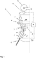
- the open-end spinning device 1 further comprises a control device 8, which is connected to the individual units 2, 4, 6, 10, 11 and a yarn return device 7 via control lines (dotted lines shown). Via the control lines, the control device 8 can send control signals to the individual units 2, 4, 6, 7, 10, 11 and, if appropriate, further units and conversely receive sensor data and operating data from them.
- the control device 8 can both a spinning station own control device 8 as well as a central control device 8 of the spinning machine or a control device of a movable maintenance device. It is also possible that several control devices 8 of the open-end spinning device 1, the spinning machine or a section of the spinning machine work together as a control device 8 a movable maintenance device.
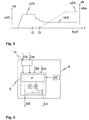
- the timing of such a piecing process will now be described with reference to FIG. 2 described.
- the time t is plotted on the right-hand axis, while the feed speed vS and the withdrawal speed vA are plotted on the vertical axis.
- the solid line represents the course of the feed speed vS over time, while the dashed line represents the curve of the take-off speed vA over time.
- the time t0 continues to represent in the present representation, the time of the actual piecing, namely the dropping of the thread end 3 ', in the spinning element 2.
- the feed speed vS is reduced stepwise from the feed rate vVS to the piecing feed rate vAS.
- the amount of fiber in the spinning rotor are regulated in order to compensate for the always occurring at characteristic points in the piecing thick and thin places.
- a first thin spot always forms following the overlapping region of the returned thread end 3 'with the fiber ring located in the spinning element 2.
- a second thin spot always occurs following the binding of such a fiber ring.
- an expert system 9 calculates at least the time t1, t2 of the occurrence of at least one thin spot in the piecing as precisely as possible in advance.
- FIG. 3 A schematic representation of the expert system 9 is shown in FIG. 3 shown.
- the expert system 9 is associated with or part of the control device 8.
- the control device 8 further includes an input device 14, by means of which an operator can input current spinning operation data DS and the piecing data DA relating to the generation of the desired piecing device.
- the spinning operation data DS include both operating data of the spinning device itself, such as execution and speeds of certain aggregates, as well as the respective application data such as the fiber material, the yarn count and other yarn related data. As the figure can be seen, However, it is not absolutely necessary to enter this data by an operator via the input device 16. It is also possible that the expert system 9 receives the spinning operation data DS directly or partially from the control device 8 in full. If, in particular, the data relating to the respective application were entered into the control device 8 at the beginning of the spinning process, it is also possible that the expert system 9 independently calculates the piecing data DA.
- a plurality of empirical data DE are further deposited, which are assigned, for example, to different types of material and / or different yarn characteristics and / or different operating data of the spinning device.
- the expert system 9 further includes a plurality of calculation formulas F, by means of which the spinning operation data DS, the piecing data DA and the empirical data DE, possibly after processing, can be linked to each other therefrom suitable settings ES for the control of the feed device and settings EA for To calculate or determine the control of the trigger device.
- suitable settings ES for the feed device 4 are initially calculated.
- the settings ES and the spinning operation data DS, the piecing data DA and the empirical data DE it is now possible for the expert system 9 to calculate the time of occurrence of a thin spot very accurately.
- both the time t1 of the occurrence of the first thin spot and the time t2 of the occurrence of the second thin spot are calculated and, based on this, the settings EA for controlling the draw-off device 6 are generated. It is not absolutely necessary to use all data and settings DS, DA, DE and ES for the calculation of the thin sites, although of course, using multiple data, a more accurate calculation of the occurrence of the thin sites can take place.
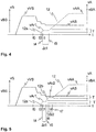
- FIG. 4 now schematically shows a piecing process, in which the time t1, t2 of the occurrence of thin sites was calculated in advance and based on the trigger device 6 is driven with the previously described settings EA.
- the type of representation corresponds to the FIG. 2 described below, so that in the following only to the differences to FIG. 2 will be received.
- FIG. 4 can be taken, the calculated by the expert system 9 time t1 of the occurrence of a thin spot, in this case the first thin spot, plotted on the time axis t.
- the settings EA for the control of the drawing-off device 6 are now calculated so that the drawing-off device 6 is driven in advance at the time t1 with a take-off speed VAr1 which is reduced with respect to the piecing take-off speed vAA.
- the withdrawal speed vA By reducing the withdrawal speed vA, the amount of fiber in the piecing is temporarily increased.
- time t1 in this case would refer to the time of occurrence of the second thin spot and would accordingly be shifted a little to the right on the time axis t.
- FIG. 5 further shows a method for piecing a thread, in which a compensation of both the first and second thin point Dünnstelle is performed.
- the drawing-off device 6 is accelerated to a second predetermined reduced drawing speed VAr2 after the first predetermined period of time ⁇ t1 in a second acceleration phase 12b leading to the time of occurrence of the second thin spot, which in the present case is designated t2, and starting from the time t6 starting for a second, predetermined period of time .DELTA.t2 kept constant until this time at the time t7.
- a tolerance range T for both the first withdrawal speed VAr1 and for the second withdrawal speed VAr2 and operate the trigger device 6 for the duration .DELTA.t1, .DELTA.t2 each within this tolerance range T, which in turn also a History for the reduced take-off speed VAr1 and / or for the reduced take-off speed VAr2 can be specified.
- control device a plurality of empirically determined function curves for the controller the deduction device 6 to deposit, which in turn are assigned to different types of material and different times t1, t2 regionally.
- the expert system 9 again calculates the times t1, t2 of the occurrence of thin spots and, based thereon, selects a suitable function curve, after which the trigger device 6 is then driven.
- the take-off speed can be set very precisely on the basis of the predicted times t1, t2 of thin locations. It has been found that, in contrast to a control of the feed device by the regulation of the thread take-off a very accurate and more direct regulation of the amount of fiber in the piecing is possible. The occurring thin areas can thus be almost completely compensated and new thread breaks can be avoided.
Landscapes
- Engineering & Computer Science (AREA)
- Mechanical Engineering (AREA)
- Textile Engineering (AREA)
- Spinning Or Twisting Of Yarns (AREA)
Claims (13)
- Procédé pour rattacher un fil (3) dans un métier à filer à bout libre (1) comportant un élément de filage (2) au moyen d'un système expert (9), dans lequel, pour former une rattache, une matière fibreuse (5) à filer est amenée à l'élément de filage (2) par un dispositif d'alimentation (4), une extrémité (3') de fil est ramenée à l'élément de filage (2) et le fil (3) nouvellement rattaché est extrait à l'aide d'un dispositif d'extraction (6), dans lequel au moins le dispositif d'alimentation (4) et le dispositif d'extraction (6) sont commandés par un dispositif de commande (8) du métier à filer à bout libre (1) et dans lequel des réglages (ES, EA) pour commander le dispositif d'alimentation (4) et le dispositif d'extraction (6) par le système expert (9) sont déterminés à partir de données (DE) empiriques enregistrées dans le dispositif de commande (8) ainsi que de données d' opération de filage (DS) actuelles et de données de rattache (DA) saisies dans le dispositif de commande (8), caractérisé en ce que le système expert (9) détermine au préalable au moins un instant (t1, t2) de l'occurrence d'au moins un amincissement, en particulier d'un premier et/ou d'un second amincissement dans la rattache, et le/les instant(s) calculé(s) (t1, t2) sont utilisés pour déterminer les réglages (EA) pour commander le dispositif d'extraction (6), sachant qu'à l'aide des réglages (EA) déterminés, une vitesse d'extraction (vA) du dispositif d'extraction (6) est commandée de sorte que le au moins un amincissement, en particulier le premier et/ou le second amincissement, soit/soient au moins partiellement compensé(s).
- Procédé selon la revendication précédente, caractérisé en ce que le dispositif d'extraction (6) est entraîné par le dispositif de commande (8) en avance ou au plus tard à l'instant (t1, t2) de l'occurrence de l'au moins un amincissement à une vitesse d'extraction (vAr1, vAr2) réduite par rapport à une vitesse d'extraction d' opération (vBA) et/ou par rapport à une vitesse de rattachement-extraction (vAA).
- Procédé selon l'une des revendications précédentes, caractérisé en ce que , après le retour de l'extrémité (3') de fil, le dispositif d'extraction (6) est d'abord accéléré à une vitesse de rattachement-extraction (vAA) réduite par rapport à une vitesse d'extraction d' opération (vBA).
- Procédé selon l'une des revendications précédentes, caractérisé en ce que le dispositif d'extraction (6), avant d'atteindre la vitesse de rattachement-extraction (vAA) et/ou avant d'atteindre la vitesse d'extraction d' opération (vBA), est d'abord accéléré à une première vitesse d'extraction (vAr1) prédéterminée réduite dans une première phase d'accélération (12a), et est ensuite entraîné à la première vitesse d'extraction (vAr1) pendant une première durée prédéterminée (Δt1) ou est entraîné pendant une première durée prédéterminée (Δt1) dans une plage de tolérance (T) étroite de ±40% au maximum, de préférence, de ±30% au maximum, de manière particulièrement préférée, de ±20% au maximum de la première vitesse d'extraction (vAr1).
- Procédé selon la revendication précédente, caractérisé en ce que le dispositif d'extraction (6), après la première durée prédéterminée (Δt1) et avant d'atteindre la vitesse de rattachement-extraction (vAA) et/ou avant d'atteindre la vitesse d'extraction d' opération (vBA), est accéléré à une seconde vitesse d'extraction (vAr2) prédéterminée réduite dans une seconde phase d'accélération (12b), et est ensuite entraîné à la seconde vitesse d'extraction (vAr2) pendant une seconde duré prédéterminée (Δt2) ou est entraîné pendant une seconde durée prédéterminée (Δt2) dans une plage de tolérance (T) étroite de ±40% au maximum, de préférence, de ±30% au maximum, de manière particulièrement préférée, de ±20% au maximum de la seconde vitesse d'extraction (vAr2) réduite.
- Procédé selon l'une des revendications précédentes, caractérisé en ce qu' une multitude de courbes de fonction pour commander le dispositif d'extraction (6) sont enregistrées dans le dispositif de commande (8) et en ce que le système expert (9) détermine une courbe de fonction appropriée pour commander le dispositif d'extraction (6) en fonction de l'instant calculé (t1, t2) de l'occurrence de l'au moins un amincissement.
- Procédé selon l'une des revendications 4 à 6, caractérisé en ce que les réglages (EA) déterminés par le système expert (9) pour commander le dispositif d'extraction (6) comprennent au moins un instant de commencement (t4, t6), la durée (Δt1, Δt2) d'entraînement à la vitesse d'extraction réduite (vAr1, vAr2) ainsi que la valeur de la vitesse d'extraction réduite (vAr1, vAr2).
- Procédé selon la revendication précédente, caractérisé en ce que les réglages (EA) comprennent en outre la valeur d'une accélération pour atteindre la vitesse de rattachement-extraction (vAA) et/ou la vitesse d'extraction d'opération (vBA).
- Procédé selon l'une des revendications précédentes, caractérisé en ce que les réglages (EA) pour la commande du dispositif d'extraction (6) sont déterminés par le système expert (9) en fonction d'un type de matière d'une matière fibreuse (5) à filer et/ou d'une finesse de fil du fil (3).
- Procédé selon l'une des revendications précédentes, caractérisé en ce que des données d' opération de filage (DS) actuelles relatives à l'élément de filage (2), en particulier une circonférence du rotor, sont prises en compte lors du calcul de l'au moins un amincissement.
- Procédé selon l'une des revendications précédentes, caractérisé en ce que les réglages (ES) déterminés par le système expert (9) pour commander le dispositif d'alimentation (4) comprennent au moins le sens de rotation et le début et la fin temporels d'accélérations du dispositif d'alimentation, et en ce que ces réglages (ES) sont pris en compte dans le calcul de l'au moins un amincissement, en particulier du premier et/ou du second amincissement, dans la rattache.
- Dispositif pour rattacher un fil (3) dans un métier à filer à bout libre (1) comportant un élément de filage (2), avec une multitude d'agrégats (2, 4, 6, 7, 10, 11) participant au processus de rattachement par filage pour former une rattache, parmi lesquels au moins un dispositif d'alimentation (4) pour l'alimentation d'une matière fibreuse, un dispositif de livraison retour de fil (7) et un dispositif d'extraction (6) pour l'extraction du fil (3) nouvellement filé, sachant que le dispositif comporte un dispositif de commande (8) avec un système expert (9) et sachant que des réglages (EA, ES) pour commander le dispositif d'alimentation (4) et le dispositif d'extraction (6) peuvent être déterminés par le système expert (9) et au moins le dispositif d'alimentation (4) et le dispositif d'extraction (6) peuvent être commandés par le dispositif de commande (8) sur la base des réglages déterminés (EA, ES), en particulier pour exécuter le procédé selon l'une ou plusieurs des revendications 1 à 11, caractérisé en ce que l'instant (t1, t2) de l'occurrence d'au moins un amincissement, en particulier d'un premier et/ou d'un second amincissement, dans la rattache, peut être calculé d'avance par le système expert (9), et une vitesse d'extraction (vA) du dispositif d'extraction (6) peut être réglée de sorte que l'au moins un amincissement soit au moins partiellement compensé.
- Dispositif pour rattacher un fil (3) selon la revendication précédente, caractérisé en ce que l'entraînement du dispositif d'extraction (6) se présente sous la forme d'un moteur pas à pas.
Applications Claiming Priority (1)
| Application Number | Priority Date | Filing Date | Title |
|---|---|---|---|
| DE102016109682.2A DE102016109682A1 (de) | 2016-05-25 | 2016-05-25 | Verfahren zum Anspinnen eines Fadens in einer Offenend-Spinnvorrichtung |
Publications (2)
| Publication Number | Publication Date |
|---|---|
| EP3255183A1 EP3255183A1 (fr) | 2017-12-13 |
| EP3255183B1 true EP3255183B1 (fr) | 2019-01-30 |
Family
ID=58707366
Family Applications (1)
| Application Number | Title | Priority Date | Filing Date |
|---|---|---|---|
| EP17170742.5A Active EP3255183B1 (fr) | 2016-05-25 | 2017-05-12 | Procédé de rattachement d'un fil dans un métier à filer à bout libre |
Country Status (3)
| Country | Link |
|---|---|
| EP (1) | EP3255183B1 (fr) |
| DE (1) | DE102016109682A1 (fr) |
| TR (1) | TR201903861T4 (fr) |
Citations (5)
| Publication number | Priority date | Publication date | Assignee | Title |
|---|---|---|---|---|
| DE3716728A1 (de) | 1987-05-19 | 1988-12-01 | Schlafhorst & Co W | Verfahren und vorrichtung zum ueberwachen der anspinner in einem oe-spinnaggregat |
| EP0395880A1 (fr) | 1989-05-05 | 1990-11-07 | Rieter Ingolstadt Spinnereimaschinenbau AG | Procédé et dispositif pour le rattachement de fil dans un métier à filer à bout libre ayant un rotor de filage |
| DE4030100A1 (de) | 1990-09-22 | 1992-04-02 | Schlafhorst & Co W | Verfahren und einrichtung zum bestimmen der aenderungen von kriterien eines automatischen anspinnvorgangs |
| EP0381995B1 (fr) | 1989-02-09 | 1994-10-19 | Rieter Ingolstadt Spinnereimaschinenbau AG | Procédé et dispositif de rattache pour un métier à filer à bout libre |
| DE10327370A1 (de) | 2003-06-18 | 2005-01-13 | Rieter Ingolstadt Spinnereimaschinenbau Ag | Verfahren und Vorrichtung zum Anspinnen eines Fadens in einer Offenend-Spinnvorrichtung |
Family Cites Families (5)
| Publication number | Priority date | Publication date | Assignee | Title |
|---|---|---|---|---|
| DE2605978C2 (de) * | 1976-02-14 | 1986-06-05 | W. Schlafhorst & Co, 4050 Mönchengladbach | Vorrichtung zum Steuern des Anspinnvorgangs bei Rotor-Spinnmaschinen |
| DE3814966A1 (de) * | 1988-05-03 | 1989-11-16 | Schubert & Salzer Maschinen | Verfahren und vorrichtung zum anspinnen einer offenend-spinnvorrichtung |
| US4962640A (en) | 1989-02-06 | 1990-10-16 | Westinghouse Electric Corp. | Apparatus and method for cooling a gas turbine vane |
| DE19955674A1 (de) * | 1999-11-19 | 2001-05-23 | Schlafhorst & Co W | Anspinnvorrichtung mit einer Auswerteeinrichtung zur Ermittlung von Parametern eines automatischen Anspinnvorgangs |
| DE102007043417B4 (de) * | 2007-09-12 | 2021-03-18 | Rieter Ingolstadt Gmbh | Offenend-Spinnmaschine |
-
2016
- 2016-05-25 DE DE102016109682.2A patent/DE102016109682A1/de not_active Withdrawn
-
2017
- 2017-05-12 TR TR2019/03861T patent/TR201903861T4/tr unknown
- 2017-05-12 EP EP17170742.5A patent/EP3255183B1/fr active Active
Patent Citations (5)
| Publication number | Priority date | Publication date | Assignee | Title |
|---|---|---|---|---|
| DE3716728A1 (de) | 1987-05-19 | 1988-12-01 | Schlafhorst & Co W | Verfahren und vorrichtung zum ueberwachen der anspinner in einem oe-spinnaggregat |
| EP0381995B1 (fr) | 1989-02-09 | 1994-10-19 | Rieter Ingolstadt Spinnereimaschinenbau AG | Procédé et dispositif de rattache pour un métier à filer à bout libre |
| EP0395880A1 (fr) | 1989-05-05 | 1990-11-07 | Rieter Ingolstadt Spinnereimaschinenbau AG | Procédé et dispositif pour le rattachement de fil dans un métier à filer à bout libre ayant un rotor de filage |
| DE4030100A1 (de) | 1990-09-22 | 1992-04-02 | Schlafhorst & Co W | Verfahren und einrichtung zum bestimmen der aenderungen von kriterien eines automatischen anspinnvorgangs |
| DE10327370A1 (de) | 2003-06-18 | 2005-01-13 | Rieter Ingolstadt Spinnereimaschinenbau Ag | Verfahren und Vorrichtung zum Anspinnen eines Fadens in einer Offenend-Spinnvorrichtung |
Also Published As
| Publication number | Publication date |
|---|---|
| DE102016109682A1 (de) | 2017-11-30 |
| EP3255183A1 (fr) | 2017-12-13 |
| TR201903861T4 (tr) | 2019-05-21 |
Similar Documents
| Publication | Publication Date | Title |
|---|---|---|
| DE2725105C2 (de) | Verfahren zum Durchführen eines Anspinnvorganges und Vorrichtung zum Durchführen des Verfahrens | |
| DE2544209C2 (de) | Verfahren zum Anspinnen einzelner Spinnaggregate einer eine Vielzahl von Spinnaggregaten aufweisenden OE-Spinnmaschine | |
| EP1101846B1 (fr) | Dispositif de rattache containant un dispositif d'evaluation des paramètres d'une procedure de rattachement automatique | |
| DE3530905C2 (fr) | ||
| EP3260584B1 (fr) | Procédé destiné à optimiser la production d'une machine à filer à bout libre | |
| EP0799916A2 (fr) | Machine de peignage avec un banc d'étirage contrÔlé | |
| DE3440009C2 (de) | Verfahren und Vorrichtung zum Bilden eines Anspinners | |
| DE102007043417B4 (de) | Offenend-Spinnmaschine | |
| EP3719186B1 (fr) | Procédé de fonctionnement d'une machine textile ainsi que machine textile | |
| DE102015122391B4 (de) | Verfahren zur Steuerung eines Anspinnprozesses zum Wiederanspinnen eines Garns an einer Spinnmaschine | |
| EP0415952B1 (fr) | Procede et dispositif permettant de commencer une nouvelle filee dans un dispositif de filage open-end | |
| EP0395880B1 (fr) | Procédé et dispositif pour le rattachement de fil dans un métier à filer à bout libre ayant un rotor de filage | |
| DE102007038871B4 (de) | Verfahren zum Anspinnen an Textilmaschinen mit einer Mehrzahl von Spinnstellen | |
| EP3255183B1 (fr) | Procédé de rattachement d'un fil dans un métier à filer à bout libre | |
| EP0291710B1 (fr) | Procédé et dispositif pour surveiller la partie rattachée du fil sur un métier à filer à bout libre | |
| EP1960574A1 (fr) | Procede pour rattacher un fil ainsi que machine de filature a rotor pour la mise en uvre du procede | |
| EP0093235B1 (fr) | Procédé pour ouvrir des balles de fibres | |
| DE4321440C2 (de) | Verfahren und Vorrichtung zum Anspinnen einer Offenend-Spinnvorrichtung | |
| EP0799915A2 (fr) | Procédé et appareil pour la régulation de ruban dans une machine de cardage | |
| DE10000146A1 (de) | Verfahren und Vorrichtung zur Steuerung einer Komponente einer eine Vielzahl gleichartiger Arbeitssteilen nebeneinander aufweisenden Textilmaschine | |
| DE2856690A1 (de) | Verfahren und vorrichtung zur erzeugung kontinuierlicher fasern | |
| CH616458A5 (fr) | ||
| EP1749907B1 (fr) | Méthode de contrôle de tirage d'une zone détirage dans une machine textile, et cette machine textile | |
| EP1564317A1 (fr) | Méthode pour obtenir une partie de fil rattachée de masse constante dans un procédé de filage à vortex | |
| DE102009030677A1 (de) | Verfahren zum Betreiben einer Arbeitsstelle und Arbeitsstelle einer Offenend-Rotorspinnmaschine |
Legal Events
| Date | Code | Title | Description |
|---|---|---|---|
| PUAI | Public reference made under article 153(3) epc to a published international application that has entered the european phase |
Free format text: ORIGINAL CODE: 0009012 |
|
| STAA | Information on the status of an ep patent application or granted ep patent |
Free format text: STATUS: THE APPLICATION HAS BEEN PUBLISHED |
|
| STAA | Information on the status of an ep patent application or granted ep patent |
Free format text: STATUS: REQUEST FOR EXAMINATION WAS MADE |
|
| AK | Designated contracting states |
Kind code of ref document: A1 Designated state(s): AL AT BE BG CH CY CZ DE DK EE ES FI FR GB GR HR HU IE IS IT LI LT LU LV MC MK MT NL NO PL PT RO RS SE SI SK SM TR |
|
| AX | Request for extension of the european patent |
Extension state: BA ME |
|
| 17P | Request for examination filed |
Effective date: 20171205 |
|
| RBV | Designated contracting states (corrected) |
Designated state(s): AL AT BE BG CH CY CZ DE DK EE ES FI FR GB GR HR HU IE IS IT LI LT LU LV MC MK MT NL NO PL PT RO RS SE SI SK SM TR |
|
| GRAP | Despatch of communication of intention to grant a patent |
Free format text: ORIGINAL CODE: EPIDOSNIGR1 |
|
| STAA | Information on the status of an ep patent application or granted ep patent |
Free format text: STATUS: GRANT OF PATENT IS INTENDED |
|
| INTG | Intention to grant announced |
Effective date: 20180725 |
|
| GRAJ | Information related to disapproval of communication of intention to grant by the applicant or resumption of examination proceedings by the epo deleted |
Free format text: ORIGINAL CODE: EPIDOSDIGR1 |
|
| STAA | Information on the status of an ep patent application or granted ep patent |
Free format text: STATUS: REQUEST FOR EXAMINATION WAS MADE |
|
| INTC | Intention to grant announced (deleted) | ||
| GRAR | Information related to intention to grant a patent recorded |
Free format text: ORIGINAL CODE: EPIDOSNIGR71 |
|
| GRAS | Grant fee paid |
Free format text: ORIGINAL CODE: EPIDOSNIGR3 |
|
| STAA | Information on the status of an ep patent application or granted ep patent |
Free format text: STATUS: GRANT OF PATENT IS INTENDED |
|
| GRAA | (expected) grant |
Free format text: ORIGINAL CODE: 0009210 |
|
| STAA | Information on the status of an ep patent application or granted ep patent |
Free format text: STATUS: THE PATENT HAS BEEN GRANTED |
|
| INTG | Intention to grant announced |
Effective date: 20181213 |
|
| AK | Designated contracting states |
Kind code of ref document: B1 Designated state(s): AL AT BE BG CH CY CZ DE DK EE ES FI FR GB GR HR HU IE IS IT LI LT LU LV MC MK MT NL NO PL PT RO RS SE SI SK SM TR |
|
| REG | Reference to a national code |
Ref country code: GB Ref legal event code: FG4D Free format text: NOT ENGLISH |
|
| REG | Reference to a national code |
Ref country code: CH Ref legal event code: EP |
|
| REG | Reference to a national code |
Ref country code: AT Ref legal event code: REF Ref document number: 1093345 Country of ref document: AT Kind code of ref document: T Effective date: 20190215 |
|
| REG | Reference to a national code |
Ref country code: IE Ref legal event code: FG4D Free format text: LANGUAGE OF EP DOCUMENT: GERMAN |
|
| REG | Reference to a national code |
Ref country code: DE Ref legal event code: R096 Ref document number: 502017000708 Country of ref document: DE |
|
| REG | Reference to a national code |
Ref country code: NL Ref legal event code: MP Effective date: 20190130 |
|
| REG | Reference to a national code |
Ref country code: LT Ref legal event code: MG4D |
|
| PG25 | Lapsed in a contracting state [announced via postgrant information from national office to epo] |
Ref country code: LT Free format text: LAPSE BECAUSE OF FAILURE TO SUBMIT A TRANSLATION OF THE DESCRIPTION OR TO PAY THE FEE WITHIN THE PRESCRIBED TIME-LIMIT Effective date: 20190130 Ref country code: SE Free format text: LAPSE BECAUSE OF FAILURE TO SUBMIT A TRANSLATION OF THE DESCRIPTION OR TO PAY THE FEE WITHIN THE PRESCRIBED TIME-LIMIT Effective date: 20190130 Ref country code: NL Free format text: LAPSE BECAUSE OF FAILURE TO SUBMIT A TRANSLATION OF THE DESCRIPTION OR TO PAY THE FEE WITHIN THE PRESCRIBED TIME-LIMIT Effective date: 20190130 Ref country code: FI Free format text: LAPSE BECAUSE OF FAILURE TO SUBMIT A TRANSLATION OF THE DESCRIPTION OR TO PAY THE FEE WITHIN THE PRESCRIBED TIME-LIMIT Effective date: 20190130 Ref country code: PT Free format text: LAPSE BECAUSE OF FAILURE TO SUBMIT A TRANSLATION OF THE DESCRIPTION OR TO PAY THE FEE WITHIN THE PRESCRIBED TIME-LIMIT Effective date: 20190530 Ref country code: NO Free format text: LAPSE BECAUSE OF FAILURE TO SUBMIT A TRANSLATION OF THE DESCRIPTION OR TO PAY THE FEE WITHIN THE PRESCRIBED TIME-LIMIT Effective date: 20190430 Ref country code: ES Free format text: LAPSE BECAUSE OF FAILURE TO SUBMIT A TRANSLATION OF THE DESCRIPTION OR TO PAY THE FEE WITHIN THE PRESCRIBED TIME-LIMIT Effective date: 20190130 Ref country code: PL Free format text: LAPSE BECAUSE OF FAILURE TO SUBMIT A TRANSLATION OF THE DESCRIPTION OR TO PAY THE FEE WITHIN THE PRESCRIBED TIME-LIMIT Effective date: 20190130 |
|
| PG25 | Lapsed in a contracting state [announced via postgrant information from national office to epo] |
Ref country code: IS Free format text: LAPSE BECAUSE OF FAILURE TO SUBMIT A TRANSLATION OF THE DESCRIPTION OR TO PAY THE FEE WITHIN THE PRESCRIBED TIME-LIMIT Effective date: 20190530 Ref country code: GR Free format text: LAPSE BECAUSE OF FAILURE TO SUBMIT A TRANSLATION OF THE DESCRIPTION OR TO PAY THE FEE WITHIN THE PRESCRIBED TIME-LIMIT Effective date: 20190501 Ref country code: LV Free format text: LAPSE BECAUSE OF FAILURE TO SUBMIT A TRANSLATION OF THE DESCRIPTION OR TO PAY THE FEE WITHIN THE PRESCRIBED TIME-LIMIT Effective date: 20190130 Ref country code: HR Free format text: LAPSE BECAUSE OF FAILURE TO SUBMIT A TRANSLATION OF THE DESCRIPTION OR TO PAY THE FEE WITHIN THE PRESCRIBED TIME-LIMIT Effective date: 20190130 Ref country code: RS Free format text: LAPSE BECAUSE OF FAILURE TO SUBMIT A TRANSLATION OF THE DESCRIPTION OR TO PAY THE FEE WITHIN THE PRESCRIBED TIME-LIMIT Effective date: 20190130 Ref country code: BG Free format text: LAPSE BECAUSE OF FAILURE TO SUBMIT A TRANSLATION OF THE DESCRIPTION OR TO PAY THE FEE WITHIN THE PRESCRIBED TIME-LIMIT Effective date: 20190430 |
|
| REG | Reference to a national code |
Ref country code: DE Ref legal event code: R026 Ref document number: 502017000708 Country of ref document: DE |
|
| PG25 | Lapsed in a contracting state [announced via postgrant information from national office to epo] |
Ref country code: CZ Free format text: LAPSE BECAUSE OF FAILURE TO SUBMIT A TRANSLATION OF THE DESCRIPTION OR TO PAY THE FEE WITHIN THE PRESCRIBED TIME-LIMIT Effective date: 20190130 Ref country code: RO Free format text: LAPSE BECAUSE OF FAILURE TO SUBMIT A TRANSLATION OF THE DESCRIPTION OR TO PAY THE FEE WITHIN THE PRESCRIBED TIME-LIMIT Effective date: 20190130 Ref country code: EE Free format text: LAPSE BECAUSE OF FAILURE TO SUBMIT A TRANSLATION OF THE DESCRIPTION OR TO PAY THE FEE WITHIN THE PRESCRIBED TIME-LIMIT Effective date: 20190130 Ref country code: DK Free format text: LAPSE BECAUSE OF FAILURE TO SUBMIT A TRANSLATION OF THE DESCRIPTION OR TO PAY THE FEE WITHIN THE PRESCRIBED TIME-LIMIT Effective date: 20190130 Ref country code: SK Free format text: LAPSE BECAUSE OF FAILURE TO SUBMIT A TRANSLATION OF THE DESCRIPTION OR TO PAY THE FEE WITHIN THE PRESCRIBED TIME-LIMIT Effective date: 20190130 Ref country code: AL Free format text: LAPSE BECAUSE OF FAILURE TO SUBMIT A TRANSLATION OF THE DESCRIPTION OR TO PAY THE FEE WITHIN THE PRESCRIBED TIME-LIMIT Effective date: 20190130 |
|
| PLBI | Opposition filed |
Free format text: ORIGINAL CODE: 0009260 |
|
| PLAX | Notice of opposition and request to file observation + time limit sent |
Free format text: ORIGINAL CODE: EPIDOSNOBS2 |
|
| PG25 | Lapsed in a contracting state [announced via postgrant information from national office to epo] |
Ref country code: SM Free format text: LAPSE BECAUSE OF FAILURE TO SUBMIT A TRANSLATION OF THE DESCRIPTION OR TO PAY THE FEE WITHIN THE PRESCRIBED TIME-LIMIT Effective date: 20190130 |
|
| 26 | Opposition filed |
Opponent name: SAURER SPINNING SOLUTIONS GMBH & CO. KG Effective date: 20191030 |
|
| PG25 | Lapsed in a contracting state [announced via postgrant information from national office to epo] |
Ref country code: MC Free format text: LAPSE BECAUSE OF FAILURE TO SUBMIT A TRANSLATION OF THE DESCRIPTION OR TO PAY THE FEE WITHIN THE PRESCRIBED TIME-LIMIT Effective date: 20190130 |
|
| REG | Reference to a national code |
Ref country code: BE Ref legal event code: MM Effective date: 20190531 |
|
| PG25 | Lapsed in a contracting state [announced via postgrant information from national office to epo] |
Ref country code: SI Free format text: LAPSE BECAUSE OF FAILURE TO SUBMIT A TRANSLATION OF THE DESCRIPTION OR TO PAY THE FEE WITHIN THE PRESCRIBED TIME-LIMIT Effective date: 20190130 Ref country code: LU Free format text: LAPSE BECAUSE OF NON-PAYMENT OF DUE FEES Effective date: 20190512 |
|
| PLBB | Reply of patent proprietor to notice(s) of opposition received |
Free format text: ORIGINAL CODE: EPIDOSNOBS3 |
|
| PG25 | Lapsed in a contracting state [announced via postgrant information from national office to epo] |
Ref country code: IE Free format text: LAPSE BECAUSE OF NON-PAYMENT OF DUE FEES Effective date: 20190512 |
|
| PG25 | Lapsed in a contracting state [announced via postgrant information from national office to epo] |
Ref country code: BE Free format text: LAPSE BECAUSE OF NON-PAYMENT OF DUE FEES Effective date: 20190531 |
|
| PG25 | Lapsed in a contracting state [announced via postgrant information from national office to epo] |
Ref country code: FR Free format text: LAPSE BECAUSE OF NON-PAYMENT OF DUE FEES Effective date: 20190531 |
|
| PG25 | Lapsed in a contracting state [announced via postgrant information from national office to epo] |
Ref country code: LI Free format text: LAPSE BECAUSE OF NON-PAYMENT OF DUE FEES Effective date: 20200531 Ref country code: CH Free format text: LAPSE BECAUSE OF NON-PAYMENT OF DUE FEES Effective date: 20200531 |
|
| REG | Reference to a national code |
Ref country code: DE Ref legal event code: R100 Ref document number: 502017000708 Country of ref document: DE |
|
| PLCK | Communication despatched that opposition was rejected |
Free format text: ORIGINAL CODE: EPIDOSNREJ1 |
|
| PG25 | Lapsed in a contracting state [announced via postgrant information from national office to epo] |
Ref country code: CY Free format text: LAPSE BECAUSE OF FAILURE TO SUBMIT A TRANSLATION OF THE DESCRIPTION OR TO PAY THE FEE WITHIN THE PRESCRIBED TIME-LIMIT Effective date: 20190130 |
|
| PLBN | Opposition rejected |
Free format text: ORIGINAL CODE: 0009273 |
|
| STAA | Information on the status of an ep patent application or granted ep patent |
Free format text: STATUS: OPPOSITION REJECTED |
|
| PG25 | Lapsed in a contracting state [announced via postgrant information from national office to epo] |
Ref country code: HU Free format text: LAPSE BECAUSE OF FAILURE TO SUBMIT A TRANSLATION OF THE DESCRIPTION OR TO PAY THE FEE WITHIN THE PRESCRIBED TIME-LIMIT; INVALID AB INITIO Effective date: 20170512 Ref country code: MT Free format text: LAPSE BECAUSE OF FAILURE TO SUBMIT A TRANSLATION OF THE DESCRIPTION OR TO PAY THE FEE WITHIN THE PRESCRIBED TIME-LIMIT Effective date: 20190130 |
|
| 27O | Opposition rejected |
Effective date: 20210311 |
|
| GBPC | Gb: european patent ceased through non-payment of renewal fee |
Effective date: 20210512 |
|
| PG25 | Lapsed in a contracting state [announced via postgrant information from national office to epo] |
Ref country code: GB Free format text: LAPSE BECAUSE OF NON-PAYMENT OF DUE FEES Effective date: 20210512 |
|
| PG25 | Lapsed in a contracting state [announced via postgrant information from national office to epo] |
Ref country code: MK Free format text: LAPSE BECAUSE OF FAILURE TO SUBMIT A TRANSLATION OF THE DESCRIPTION OR TO PAY THE FEE WITHIN THE PRESCRIBED TIME-LIMIT Effective date: 20190130 |
|
| P01 | Opt-out of the competence of the unified patent court (upc) registered |
Effective date: 20230329 |
|
| REG | Reference to a national code |
Ref country code: AT Ref legal event code: MM01 Ref document number: 1093345 Country of ref document: AT Kind code of ref document: T Effective date: 20220512 |
|
| PG25 | Lapsed in a contracting state [announced via postgrant information from national office to epo] |
Ref country code: AT Free format text: LAPSE BECAUSE OF NON-PAYMENT OF DUE FEES Effective date: 20220512 |
|
| PGFP | Annual fee paid to national office [announced via postgrant information from national office to epo] |
Ref country code: IT Payment date: 20230529 Year of fee payment: 7 |
|
| PGFP | Annual fee paid to national office [announced via postgrant information from national office to epo] |
Ref country code: TR Payment date: 20230509 Year of fee payment: 7 |
|
| REG | Reference to a national code |
Ref country code: DE Ref legal event code: R081 Ref document number: 502017000708 Country of ref document: DE Owner name: SPINDELFABRIK SUESSEN GMBH, DE Free format text: FORMER OWNER: RIETER INGOLSTADT GMBH, 85055 INGOLSTADT, DE |
|
| PG25 | Lapsed in a contracting state [announced via postgrant information from national office to epo] |
Ref country code: IT Free format text: LAPSE BECAUSE OF NON-PAYMENT OF DUE FEES Effective date: 20240512 |
|
| PGFP | Annual fee paid to national office [announced via postgrant information from national office to epo] |
Ref country code: DE Payment date: 20250602 Year of fee payment: 9 |