EP3255246B1 - Turbinenkomponente und verfahren zur herstellung und kühlung einer turbinenkomponente - Google Patents
Turbinenkomponente und verfahren zur herstellung und kühlung einer turbinenkomponente Download PDFInfo
- Publication number
- EP3255246B1 EP3255246B1 EP17174321.4A EP17174321A EP3255246B1 EP 3255246 B1 EP3255246 B1 EP 3255246B1 EP 17174321 A EP17174321 A EP 17174321A EP 3255246 B1 EP3255246 B1 EP 3255246B1
- Authority
- EP
- European Patent Office
- Prior art keywords
- trailing edge
- airfoil
- edge portion
- radial
- turbine component
- Prior art date
- Legal status (The legal status is an assumption and is not a legal conclusion. Google has not performed a legal analysis and makes no representation as to the accuracy of the status listed.)
- Active
Links
Images



Classifications
-
- F—MECHANICAL ENGINEERING; LIGHTING; HEATING; WEAPONS; BLASTING
- F01—MACHINES OR ENGINES IN GENERAL; ENGINE PLANTS IN GENERAL; STEAM ENGINES
- F01D—NON-POSITIVE DISPLACEMENT MACHINES OR ENGINES, e.g. STEAM TURBINES
- F01D5/00—Blades; Blade-carrying members; Heating, heat-insulating, cooling or antivibration means on the blades or the members
- F01D5/12—Blades
- F01D5/14—Form or construction
- F01D5/18—Hollow blades, i.e. blades with cooling or heating channels or cavities; Heating, heat-insulating or cooling means on blades
- F01D5/187—Convection cooling
-
- F—MECHANICAL ENGINEERING; LIGHTING; HEATING; WEAPONS; BLASTING
- F01—MACHINES OR ENGINES IN GENERAL; ENGINE PLANTS IN GENERAL; STEAM ENGINES
- F01D—NON-POSITIVE DISPLACEMENT MACHINES OR ENGINES, e.g. STEAM TURBINES
- F01D25/00—Component parts, details, or accessories, not provided for in, or of interest apart from, other groups
- F01D25/08—Cooling; Heating; Heat-insulation
- F01D25/12—Cooling
-
- F—MECHANICAL ENGINEERING; LIGHTING; HEATING; WEAPONS; BLASTING
- F01—MACHINES OR ENGINES IN GENERAL; ENGINE PLANTS IN GENERAL; STEAM ENGINES
- F01D—NON-POSITIVE DISPLACEMENT MACHINES OR ENGINES, e.g. STEAM TURBINES
- F01D5/00—Blades; Blade-carrying members; Heating, heat-insulating, cooling or antivibration means on the blades or the members
- F01D5/12—Blades
- F01D5/14—Form or construction
- F01D5/147—Construction, i.e. structural features, e.g. of weight-saving hollow blades
-
- F—MECHANICAL ENGINEERING; LIGHTING; HEATING; WEAPONS; BLASTING
- F01—MACHINES OR ENGINES IN GENERAL; ENGINE PLANTS IN GENERAL; STEAM ENGINES
- F01D—NON-POSITIVE DISPLACEMENT MACHINES OR ENGINES, e.g. STEAM TURBINES
- F01D5/00—Blades; Blade-carrying members; Heating, heat-insulating, cooling or antivibration means on the blades or the members
- F01D5/12—Blades
- F01D5/28—Selecting particular materials; Particular measures relating thereto; Measures against erosion or corrosion
- F01D5/282—Selecting composite materials, e.g. blades with reinforcing filaments
-
- F—MECHANICAL ENGINEERING; LIGHTING; HEATING; WEAPONS; BLASTING
- F01—MACHINES OR ENGINES IN GENERAL; ENGINE PLANTS IN GENERAL; STEAM ENGINES
- F01D—NON-POSITIVE DISPLACEMENT MACHINES OR ENGINES, e.g. STEAM TURBINES
- F01D9/00—Stators
- F01D9/02—Nozzles; Nozzle boxes; Stator blades; Guide conduits, e.g. individual nozzles
-
- F—MECHANICAL ENGINEERING; LIGHTING; HEATING; WEAPONS; BLASTING
- F05—INDEXING SCHEMES RELATING TO ENGINES OR PUMPS IN VARIOUS SUBCLASSES OF CLASSES F01-F04
- F05D—INDEXING SCHEME FOR ASPECTS RELATING TO NON-POSITIVE-DISPLACEMENT MACHINES OR ENGINES, GAS-TURBINES OR JET-PROPULSION PLANTS
- F05D2220/00—Application
- F05D2220/30—Application in turbines
-
- F—MECHANICAL ENGINEERING; LIGHTING; HEATING; WEAPONS; BLASTING
- F05—INDEXING SCHEMES RELATING TO ENGINES OR PUMPS IN VARIOUS SUBCLASSES OF CLASSES F01-F04
- F05D—INDEXING SCHEME FOR ASPECTS RELATING TO NON-POSITIVE-DISPLACEMENT MACHINES OR ENGINES, GAS-TURBINES OR JET-PROPULSION PLANTS
- F05D2230/00—Manufacture
- F05D2230/20—Manufacture essentially without removing material
- F05D2230/22—Manufacture essentially without removing material by sintering
-
- F—MECHANICAL ENGINEERING; LIGHTING; HEATING; WEAPONS; BLASTING
- F05—INDEXING SCHEMES RELATING TO ENGINES OR PUMPS IN VARIOUS SUBCLASSES OF CLASSES F01-F04
- F05D—INDEXING SCHEME FOR ASPECTS RELATING TO NON-POSITIVE-DISPLACEMENT MACHINES OR ENGINES, GAS-TURBINES OR JET-PROPULSION PLANTS
- F05D2230/00—Manufacture
- F05D2230/20—Manufacture essentially without removing material
- F05D2230/23—Manufacture essentially without removing material by permanently joining parts together
- F05D2230/232—Manufacture essentially without removing material by permanently joining parts together by welding
- F05D2230/237—Brazing
-
- F—MECHANICAL ENGINEERING; LIGHTING; HEATING; WEAPONS; BLASTING
- F05—INDEXING SCHEMES RELATING TO ENGINES OR PUMPS IN VARIOUS SUBCLASSES OF CLASSES F01-F04
- F05D—INDEXING SCHEME FOR ASPECTS RELATING TO NON-POSITIVE-DISPLACEMENT MACHINES OR ENGINES, GAS-TURBINES OR JET-PROPULSION PLANTS
- F05D2230/00—Manufacture
- F05D2230/30—Manufacture with deposition of material
- F05D2230/31—Layer deposition
-
- F—MECHANICAL ENGINEERING; LIGHTING; HEATING; WEAPONS; BLASTING
- F05—INDEXING SCHEMES RELATING TO ENGINES OR PUMPS IN VARIOUS SUBCLASSES OF CLASSES F01-F04
- F05D—INDEXING SCHEME FOR ASPECTS RELATING TO NON-POSITIVE-DISPLACEMENT MACHINES OR ENGINES, GAS-TURBINES OR JET-PROPULSION PLANTS
- F05D2240/00—Components
- F05D2240/10—Stators
- F05D2240/12—Fluid guiding means, e.g. vanes
- F05D2240/122—Fluid guiding means, e.g. vanes related to the trailing edge of a stator vane
-
- F—MECHANICAL ENGINEERING; LIGHTING; HEATING; WEAPONS; BLASTING
- F05—INDEXING SCHEMES RELATING TO ENGINES OR PUMPS IN VARIOUS SUBCLASSES OF CLASSES F01-F04
- F05D—INDEXING SCHEME FOR ASPECTS RELATING TO NON-POSITIVE-DISPLACEMENT MACHINES OR ENGINES, GAS-TURBINES OR JET-PROPULSION PLANTS
- F05D2240/00—Components
- F05D2240/20—Rotors
- F05D2240/30—Characteristics of rotor blades, i.e. of any element transforming dynamic fluid energy to or from rotational energy and being attached to a rotor
- F05D2240/304—Characteristics of rotor blades, i.e. of any element transforming dynamic fluid energy to or from rotational energy and being attached to a rotor related to the trailing edge of a rotor blade
-
- F—MECHANICAL ENGINEERING; LIGHTING; HEATING; WEAPONS; BLASTING
- F05—INDEXING SCHEMES RELATING TO ENGINES OR PUMPS IN VARIOUS SUBCLASSES OF CLASSES F01-F04
- F05D—INDEXING SCHEME FOR ASPECTS RELATING TO NON-POSITIVE-DISPLACEMENT MACHINES OR ENGINES, GAS-TURBINES OR JET-PROPULSION PLANTS
- F05D2250/00—Geometry
- F05D2250/10—Two-dimensional
- F05D2250/18—Two-dimensional patterned
- F05D2250/183—Two-dimensional patterned zigzag
-
- F—MECHANICAL ENGINEERING; LIGHTING; HEATING; WEAPONS; BLASTING
- F05—INDEXING SCHEMES RELATING TO ENGINES OR PUMPS IN VARIOUS SUBCLASSES OF CLASSES F01-F04
- F05D—INDEXING SCHEME FOR ASPECTS RELATING TO NON-POSITIVE-DISPLACEMENT MACHINES OR ENGINES, GAS-TURBINES OR JET-PROPULSION PLANTS
- F05D2250/00—Geometry
- F05D2250/10—Two-dimensional
- F05D2250/18—Two-dimensional patterned
- F05D2250/184—Two-dimensional patterned sinusoidal
-
- F—MECHANICAL ENGINEERING; LIGHTING; HEATING; WEAPONS; BLASTING
- F05—INDEXING SCHEMES RELATING TO ENGINES OR PUMPS IN VARIOUS SUBCLASSES OF CLASSES F01-F04
- F05D—INDEXING SCHEME FOR ASPECTS RELATING TO NON-POSITIVE-DISPLACEMENT MACHINES OR ENGINES, GAS-TURBINES OR JET-PROPULSION PLANTS
- F05D2250/00—Geometry
- F05D2250/10—Two-dimensional
- F05D2250/18—Two-dimensional patterned
- F05D2250/185—Two-dimensional patterned serpentine-like
-
- F—MECHANICAL ENGINEERING; LIGHTING; HEATING; WEAPONS; BLASTING
- F05—INDEXING SCHEMES RELATING TO ENGINES OR PUMPS IN VARIOUS SUBCLASSES OF CLASSES F01-F04
- F05D—INDEXING SCHEME FOR ASPECTS RELATING TO NON-POSITIVE-DISPLACEMENT MACHINES OR ENGINES, GAS-TURBINES OR JET-PROPULSION PLANTS
- F05D2260/00—Function
- F05D2260/20—Heat transfer, e.g. cooling
-
- F—MECHANICAL ENGINEERING; LIGHTING; HEATING; WEAPONS; BLASTING
- F05—INDEXING SCHEMES RELATING TO ENGINES OR PUMPS IN VARIOUS SUBCLASSES OF CLASSES F01-F04
- F05D—INDEXING SCHEME FOR ASPECTS RELATING TO NON-POSITIVE-DISPLACEMENT MACHINES OR ENGINES, GAS-TURBINES OR JET-PROPULSION PLANTS
- F05D2260/00—Function
- F05D2260/20—Heat transfer, e.g. cooling
- F05D2260/204—Heat transfer, e.g. cooling by the use of microcircuits
-
- F—MECHANICAL ENGINEERING; LIGHTING; HEATING; WEAPONS; BLASTING
- F05—INDEXING SCHEMES RELATING TO ENGINES OR PUMPS IN VARIOUS SUBCLASSES OF CLASSES F01-F04
- F05D—INDEXING SCHEME FOR ASPECTS RELATING TO NON-POSITIVE-DISPLACEMENT MACHINES OR ENGINES, GAS-TURBINES OR JET-PROPULSION PLANTS
- F05D2300/00—Materials; Properties thereof
- F05D2300/10—Metals, alloys or intermetallic compounds
- F05D2300/17—Alloys
- F05D2300/175—Superalloys
-
- F—MECHANICAL ENGINEERING; LIGHTING; HEATING; WEAPONS; BLASTING
- F05—INDEXING SCHEMES RELATING TO ENGINES OR PUMPS IN VARIOUS SUBCLASSES OF CLASSES F01-F04
- F05D—INDEXING SCHEME FOR ASPECTS RELATING TO NON-POSITIVE-DISPLACEMENT MACHINES OR ENGINES, GAS-TURBINES OR JET-PROPULSION PLANTS
- F05D2300/00—Materials; Properties thereof
- F05D2300/60—Properties or characteristics given to material by treatment or manufacturing
- F05D2300/603—Composites; e.g. fibre-reinforced
- F05D2300/6033—Ceramic matrix composites [CMC]
Definitions
- the present invention is directed to methods and devices for cooling the trailing edge portion of a turbine airfoil. More specifically, the present invention is directed to methods and devices including a turbine component with radial cooling channels along the trailing edge.
- Modern high-efficiency combustion turbines have firing temperatures that exceed about 2000 °F (1093 °C), and firing temperatures continue to increase as demand for more efficient engines continues.
- Gas turbine components such as nozzles and blades, are subjected to intense heat and external pressures in the hot gas path. These rigorous operating conditions are exacerbated by advances in the technology, which may include both increased operating temperatures and greater hot gas path pressures.
- components such as nozzles and blades
- components are sometimes cooled by flowing a fluid through a manifold inserted into the core of the nozzle or blade, which exits the manifold through impingement holes into a post-impingement cavity, and which then exits the post-impingement cavity through apertures in the exterior wall of the nozzle or blade, in some cases forming a film layer of the fluid on the exterior of the nozzle or blade.
- turbine airfoils are often made primarily of a nickel-based or a cobalt-based superalloy
- turbine airfoils may alternatively have an outer portion made of one or more ceramic matrix composite (CMC) materials.
- CMC materials are generally better at handling higher temperatures than metals.
- Certain CMC materials include compositions having a ceramic matrix reinforced with coated fibers. The composition provides strong, lightweight, and heat-resistant materials with possible applications in a variety of different systems.
- the manufacture of a CMC part typically includes laying up pre-impregnated composite fibers having a matrix material already present (prepreg) to form the geometry of the part (pre-form), autoclaving and burning out the pre-form, infiltrating the burned-out pre-form with the melting matrix material, and any machining or further treatments of the pre-form.
- Infiltrating the pre-form may include depositing the ceramic matrix out of a gas mixture, pyrolyzing a pre-ceramic polymer, chemically reacting elements, sintering, generally in the temperature range of 925 to 1650 °C (1700 to 3000 °F), or electrophoretically depositing a ceramic powder.
- the CMC may be located over a metal spar to form only the outer surface of the airfoil.
- CMC materials include, but are not limited to, carbon-fiber-reinforced carbon (C/C), carbon-fiber-reinforced silicon carbide (C/SiC), silicon-carbide-fiber-reinforced silicon carbide (SiC/SiC), alumina-fiber-reinforced alumina (Al2O3/Al2O3), or combinations thereof.
- the CMC may have increased elongation, fracture toughness, thermal shock, dynamic load capability, and anisotropic properties as compared to a monolithic ceramic structure.
- US 7,670,113 describes a turbine blade having a trailing edge cooling circuit that includes a series of multiple pass serpentine flow cooling passages arranged along the trailing edge region.
- the invention relates to a turbine component according to claim 1.
- the invention further relates to a method of making a turbine component according to claim 4.
- a method and a device for cooling the trailing edge of a turbine airfoil with radial cooling channels along the trailing edge portion of the turbine airfoil are provided.
- Embodiments of the present invention for example, in comparison to concepts failing to include one or more of the features disclosed herein, provide cooling in a turbine airfoil, provide a more uniform temperature in a cooled turbine airfoil, provide a turbine airfoil with an enhanced lifespan, or combinations thereof.
- radial refers to orientation directionally between a first surface, such as lower surface 52, at a lower radial height and a second surface, such as upper surface 56, at a higher radial height from the axis of the turbine.
- a trailing edge portion refers to a portion of an airfoil at the trailing edge without chambers or other void space aside from the cooling channels formed therein, as described herein.
- a turbine component 10 includes a root 11 and an airfoil 12 extending from the root 11 at the base 13 to a tip 14 opposite the base 13.
- the turbine component 10 is a turbine nozzle.
- the turbine component 10 is a turbine blade.
- the shape of the airfoil 12 includes a leading edge 15, a trailing edge 16, a suction side 18 having a convex outer surface, and a pressure side 20 having a concave outer surface opposite the convex outer surface.
- the turbine component 10 may also include an outer sidewall at the tip 14 of the airfoil 12 similar to the root 11 at the base 13 of the airfoil 12.
- the airfoil 12 includes a ceramic matrix composite (CMC) shell 22 mounted on a metal spar 24.
- the airfoil 12 is formed as a thin CMC shell 22 of one or more layers of CMC materials over the metal spar 24. Initial thermal analysis indicates that the trailing edge portion of the CMC shell 22 of a turbine airfoil gets hot and cooling may be necessary to preserve the structural integrity.
- the airfoil 12 is alternatively formed as a metal part 30.
- the metal part is preferably a high-temperature superalloy.
- the high-temperature superalloy is a nickel-based high-temperature superalloy or a cobalt-based high-temperature superalloy.
- the radial cooling channels 40 in the trailing edge portion 42 permit a cooling fluid supplied to the lower portion at the base 13 and/or the upper portion at the tip 14 of the trailing edge portion 42 at the base 13 to flow through at least a portion of the trailing edge portion 42 and out of the lower portion at the base 13 or the upper portion at the tip 14 of the trailing edge portion 42 during operation of a turbine including the turbine component 10.
- the airfoil 12 also includes one or more chambers 32 to which cooling fluid may be provided by way of the root 11 or by way of the tip 14 of the turbine component 10.
- the trailing edge portion 42 of the turbine component 10 includes the radial cooling channels 40 that open at a first end 50 at a lower surface 52 and a second end 54 opposite the first end 50 at an upper surface 56 to provide passage of a cooling fluid in a generally radial direction through the trailing edge portion 42 of the turbine component 10.
- the trailing edge portion 42 of the turbine component 10 includes the radial cooling channels 40 that open at a first end 50 at a lower surface 52 and a second end 54 opposite the first end 50 at the lower surface 52 to provide passage of a cooling fluid through the trailing edge portion 42 of the turbine component 10.
- the trailing edge portion 42 of the turbine component 10 includes the radial cooling channels 40 that open at a first end 50 at an upper surface 56 and a second end 54 opposite the first end 50 at the upper surface 56 to provide passage of a cooling fluid through the trailing edge portion 42 of the turbine component 10.
- the trailing edge portion 42 of the turbine component 10 includes some radial cooling channels 40 that open at a first end 50 at a lower surface 52 and a second end 54 opposite the first end 50 at the lower surface 52 and some radial cooling channels 40 that open at a first end 50 at an upper surface 56 and a second end 54 opposite the first end 50 at the upper surface 56 to provide passage of a cooling fluid through the trailing edge portion 42 of the turbine component 10.
- This counter flowing design compensates for heat pick up along the length of the cooling circuit in that as an up pass radial cooling channel 40 picks up heat and becomes less efficient near its end of the circuit is compensated by the counter flowing circuit radial cooling channel 40 having little heat pick up, making the system more efficient.
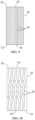
- the radial cooling channels 40 are formed substantially along the line 4-4 of the trailing edge portion 42, such as shown in FIG. 4 and FIG. 6 through FIG. 14 . In other embodiments, the radial cooling channels 40 may lie off the line 4-4 of the trailing edge portion 42 or extend into either the first section 44 or the second section 46 of the airfoil 12. Any of the contours disclosed herein may be arranged in either manner. As shown in FIG. 5 , the contours of the radial cooling channels 40 may be staggered such that neighboring radial cooling channels 40 are different distances from the surfaces of the trailing edge portion 42 at the same radial distance from the turbine axis.
- the radial cooling channels 40 in the trailing edge portion 42 may have any geometry, including, but not limited to, a wavy contour as shown in FIG. 4 through FIG. 6 , a serpentine contour as shown in FIG. 11 through FIG. 14 , a contour of abruptly varying cross sectional areas as shown in FIG. 7 , a contour of tapering cross sectional area as shown in FIG. 8 , a straight contour as shown in FIG. 9 , an irregular contour as shown in FIG. 10 , or combinations thereof.
- An irregular contour may be any non-repeating contour, such as, for example, a random contour.
- the formation of the airfoil 12 from two sections 44, 46 permits formation of radial cooling channels 40 with complex contours.
- the varying cross sectional areas of the radial cooling channels 40 of FIG. 7 promote greater heat transfer to the cooling fluid by promoting mixing of the cooling fluid.
- the radial cooling channels 40 may be formed in the trailing edge portion 42 after the formation of the airfoil 12.
- the radial cooling channels 40 are formed by stem drilling.
- the radial cooling channels 40 have a geometry that prevents their formation by stem drilling.
- the tapering cross sectional areas of the radial cooling channels 40 of FIG. 8 compensate for the increase in volume of the cooling fluid while picking up heat along the radial cooling channel 40 as the cooling fluid flows through a radial cooling channel 40.
- the tapering cross sectional areas may help to maintain a similar heat transfer pattern along the radial cooling channel 40.
- the tapering is preferably in the direction opposite of the cooling fluid flow.
- the taper orientation may be in either direction, such as the alternating directions shown in FIG. 8 or the same direction.
- the cross section of a radial cooling channel 40 may have any shape, including, but not limited to, a round shape, an elliptical shape, a racetrack shape, and a parallelogram.
- the size and shape of the cross section of the radial cooling channel 40 may vary from the first end 50 to the second end 54, depending on the local cooling effectiveness required of the channel.
- the walls of the radial cooling channel 40 may be smooth or may have one or more features to augment the internal heat transfer coefficients by disrupting the boundary layer flow, such as by turbulators located locally or all along the length of the radial cooling channel 40.
- the airfoil 12 includes a CMC shell 22
- at least a portion of the radial cooling channels 40 may be formed between layers of the CMC material.
- all of the radial cooling channels 40 are formed between CMC layers.
- the radial cooling channels 40 are formed by machining the CMC material after formation of the CMC material.
- a sacrificial material is burned or pyrolyzed out either during or after formation of the CMC material to form the radial cooling channels 40.
- the CMC shell 22 is made as two parts and glued together to form the trailing edge portion 42.
- the airfoil 12 is formed as a metal part 30 by metal three-dimensional (3D) printing.
- the metal part 30 is formed as two metal pieces that are brazed or welded together, such as, for example, along line 4-4 of FIG. 3 .
- the two pieces are a first section 44 including the suction side 18 having the convex outer surface and a second section 46 including the pressure side 20 having the concave outer surface, with at least a portion of the radial cooling channels 40 being formed at one or both of the surfaces of the sections 44, 46.
- all of the radial cooling channels 40 are formed at the surface of the sections 44, 46.
- Metal 3D printing enables precise creation of a turbine component 10 including complex radial cooling channels 40.
- metal 3D printing forms successive layers of material under computer control to create at least a portion of the turbine component 10.
- powdered metal is heated to melt or sinter the powder to the growing turbine component 10. Heating methods may include, but are not limited to, selective laser sintering (SLS), direct metal laser sintering (DMLS), selective laser melting (SLM), electron beam melting (EBM), and combinations thereof.
- SLS selective laser sintering
- DMLS direct metal laser sintering
- SLM selective laser melting
- EBM electron beam melting
- a 3D metal printer lays down metal powder, and then a high-powered laser melts that powder in certain predetermined locations based on a model from a computer-aided design (CAD) file. Once one layer is melted and formed, the 3D printer repeats the process by placing additional layers of metal powder on top of the first layer or where otherwise instructed, one at a time, until the entire metal component is
- the radial cooling channels 40 are preferably formed in the trailing edge portion 42 of the airfoil 12 to permit passage of a cooling fluid to cool the trailing edge portion 42.
- the radial cooling channels 40 may have any contour that provides passage of a cooling fluid in a generally radial direction, including, but not limited to, wavy, serpentine, varying cross sectional areas, straight, or combinations thereof.
- the dimensions, contours, and/or locations of the radial cooling channels 40 are selected to permit cooling that maintains a substantially uniform temperature in the trailing edge portion 42 during operation of a turbine including the turbine component 10.
- Radial cooling channels 40 along the trailing edge 16 of the airfoil 12 provide passageways for cooling fluid generally in the radial direction with respect to the turbine rotor.
- the radial cooling channels 40 may have any geometry, including, but not limited to, straight radial holes that may include stem-drilled holes, complex geometries such as serpentine or wavy, or combinations thereof. More complex geometries than stem-drilled holes may be accommodated in the trailing edge portion, benefitting heat transfer and uniform temperature distribution in the airfoil 12.
- the radial cooling channels 40 have variations in the cross sectional area of the radial cooling channel 40, with portions of different cross sectional area along the length of the radial cooling channels 40.
- the radial cooling channels 40 are staggered perpendicular to the turbine axis with some near the surface and some buried farther beneath the surface.
Landscapes
- Engineering & Computer Science (AREA)
- Mechanical Engineering (AREA)
- General Engineering & Computer Science (AREA)
- Chemical & Material Sciences (AREA)
- Materials Engineering (AREA)
- Architecture (AREA)
- Composite Materials (AREA)
- Turbine Rotor Nozzle Sealing (AREA)
- Welding Or Cutting Using Electron Beams (AREA)
- Laser Beam Processing (AREA)
Claims (8)
- Turbinenkomponente (10), umfassend:einen Fuß (11); undein Schaufelblatt (12), das sich von dem Fuß (11) zu einer Spitze (14) gegenüber dem Fuß (11) erstreckt, wobei das Schaufelblatt (12) eine Vorderkante (15) und einen Hinterkantenabschnitt (42) ausbildet, der sich zu einer Hinterkante (16) erstreckt;eine Vielzahl von radialen Kühlkanälen (40) in dem Hinterkantenabschnitt (42) des Schaufelblatts (12) angeordnet ist, um einen radialen Fluss eines Kühlfluids durch den Hinterkantenabschnitt (42) hindurch zu ermöglichen, wobei jeder radiale Kühlkanal ein erstes Ende (50) an einer unteren Oberfläche (52) an einer Fuß(11)-Kante des Hinterkantenabschnitts (42) oder an einer oberen Oberfläche (56) an einer Spitzen(14)-Kante des Hinterkantenabschnitts und ein zweites Ende (54) gegenüber dem ersten Ende (50) an der unteren Oberfläche (52) oder der oberen Oberfläche (56) aufweist;wobei die Vielzahl von radialen Kühlkanälen (40) in dem Hinterkantenabschnitt eine radiale Geometrie aufweist, die aus der Gruppe ausgewählt ist, bestehend aus gewellt, gewunden, unregelmäßig und Kombinationen davon;dadurch gekennzeichnet, dassdas Schaufelblatt (12) einen dreidimensional metallgedruckten ersten Bereich und einen dreidimensional metallgedruckten zweiten Bereich (46) umfasst, wobei der erste Bereich mit dem zweiten Bereich (46) verschweißt oder hartgelötet ist, um das Schaufelblatt (12) auszubilden, wobei mindestens ein Abschnitt der Vielzahl von radialen Kühlkanälen (40) an einer ausgebildeten Oberfläche des ersten Bereichs oder des zweiten Bereichs (46) ausgebildet ist.
- Turbinenkomponente (10) nach Anspruch 1, wobei das Schaufelblatt (12) einen Metallholm (24) und eine Hülle über dem Metallholm (24) umfasst, die Hülle umfassend einen Keramikmatrix-Verbundwerkstoff.
- Turbinenkomponente (10) nach Anspruch 1, wobei das Schaufelblatt (12) aus einer Hochtemperatursuperlegierung ausgebildet ist.
- Verfahren zum Herstellen einer Turbinenkomponente (10), umfassend:Ausbilden eines Schaufelblatts (12), das eine Vorderkante (15) und einen Hinterkantenabschnitt (42) aufweist, der sich zu einer Hinterkante (16) erstreckt;wobei das Verfahren gekennzeichnet ist durch:Ausbilden einer Vielzahl von radialen Kühlkanälen (40) in dem Hinterkantenabschnitt (42), wobei die Vielzahl von radialen Kühlkanälen (40) angeordnet ist, um einen radialen Fluss eines Kühlfluids durch den Hinterkantenabschnitt (42) hindurch zu ermöglichen, wobei jeder radiale Kühlkanal ein erstes Ende (50) an einer unteren Oberfläche (52) an einer Fuß(11)-Kante des Hinterkantenabschnitts (42) oder an einer oberen Oberfläche (56) an einer Spitzen(14)-Kante des Hinterkantenabschnitts (42) und ein zweites Ende (54) gegenüber dem ersten Ende (50) an der unteren Oberfläche (52) oder der oberen Oberfläche (56) aufweist, und die radiale Geometrie der Kühlkanäle in dem Hinterkantenabschnitt aus der Gruppe ausgewählt ist, bestehend aus gewellt, gewunden, unregelmäßig und Kombinationen davon besteht;wobei das Ausbilden das dreidimensionale Metalldrucken eines ersten Bereichs und eines zweiten Bereichs (46) und das Verschweißen oder das Hartlöten des ersten Bereichs zu dem zweiten Bereich (46) umfasst, um das Schaufelblatt (12) auszubilden, wobei mindestens ein Abschnitt der Vielzahl von radialen Kühlkanälen (40) an einer ausgebildeten Oberfläche des ersten Bereichs oder des zweiten Bereichs (46) ausgebildet wird.
- Verfahren nach Anspruch 4, wobei das Ausbilden das Ausbilden einer Hülle über einem Metallholm (24) umfasst, um das Schaufelblatt (12) auszubilden, wobei die Hülle ein Keramikmatrix-Verbundmaterial umfasst.
- Verfahren nach Anspruch 5, ferner umfassend das Ausbilden mindestens eines Abschnitts der Vielzahl von radialen Kühlkanälen (40) zwischen Schichten des Keramikmatrix-Verbundmaterials.
- Verfahren nach Anspruch 4, wobei das Ausbilden das dreidimensionale Metalldrucken einer Hochtemperatursuperlegierung umfasst, um das Schaufelblatt (12) auszubilden.
- Verfahren zum Kühlen einer Turbinenkomponente (10), umfassend:Zuführen eines Kühlfluids zu einem Innenraum der Turbinenkomponente (10), wobei die Turbinenkomponente (10) gemäß einem der Ansprüche 1 bis 3 ist; undLeiten des Kühlfluids durch die Vielzahl von radialen Kühlkanälen (40) hindurch durch den Hinterkantenabschnitt (42) des Schaufelblatts (12) hindurch.
Applications Claiming Priority (1)
| Application Number | Priority Date | Filing Date | Title |
|---|---|---|---|
| US15/174,271 US10472973B2 (en) | 2016-06-06 | 2016-06-06 | Turbine component and methods of making and cooling a turbine component |
Publications (2)
| Publication Number | Publication Date |
|---|---|
| EP3255246A1 EP3255246A1 (de) | 2017-12-13 |
| EP3255246B1 true EP3255246B1 (de) | 2023-08-09 |
Family
ID=59009577
Family Applications (1)
| Application Number | Title | Priority Date | Filing Date |
|---|---|---|---|
| EP17174321.4A Active EP3255246B1 (de) | 2016-06-06 | 2017-06-02 | Turbinenkomponente und verfahren zur herstellung und kühlung einer turbinenkomponente |
Country Status (3)
| Country | Link |
|---|---|
| US (2) | US10472973B2 (de) |
| EP (1) | EP3255246B1 (de) |
| JP (1) | JP7094664B2 (de) |
Families Citing this family (8)
| Publication number | Priority date | Publication date | Assignee | Title |
|---|---|---|---|---|
| KR102153064B1 (ko) * | 2018-10-22 | 2020-09-07 | 두산중공업 주식회사 | 터빈 블레이드 및 이를 포함하는 가스 터빈 |
| US11591329B2 (en) * | 2019-07-09 | 2023-02-28 | Incyte Corporation | Bicyclic heterocycles as FGFR inhibitors |
| KR102241876B1 (ko) * | 2019-07-31 | 2021-04-19 | 한국항공우주연구원 | 적층제조방식을 이용한 고온부품 및 그 제조방법 |
| WO2021067979A1 (en) * | 2019-10-04 | 2021-04-08 | Siemens Aktiengesellschaft | Composite layer system having an additively manufactured substrate and a thermal protection system |
| US11667091B2 (en) * | 2019-12-03 | 2023-06-06 | GM Global Technology Operations LLC | Methods for forming vascular components |
| US11338512B2 (en) * | 2019-12-03 | 2022-05-24 | GM Global Technology Operations LLC | Method of forming channels within a substrate |
| US11326470B2 (en) * | 2019-12-20 | 2022-05-10 | General Electric Company | Ceramic matrix composite component including counterflow channels and method of producing |
| US12467369B2 (en) | 2023-08-22 | 2025-11-11 | General Electric Company | Composite component having an additively printed inner portion |
Family Cites Families (35)
| Publication number | Priority date | Publication date | Assignee | Title |
|---|---|---|---|---|
| US3533712A (en) | 1966-02-26 | 1970-10-13 | Gen Electric | Cooled vane structure for high temperature turbines |
| US3736071A (en) | 1970-11-27 | 1973-05-29 | Gen Electric | Bucket tip/collection slot combination for open-circuit liquid-cooled gas turbines |
| US4214355A (en) * | 1977-12-21 | 1980-07-29 | General Electric Company | Method for repairing a turbomachinery blade tip |
| US4376004A (en) * | 1979-01-16 | 1983-03-08 | Westinghouse Electric Corp. | Method of manufacturing a transpiration cooled ceramic blade for a gas turbine |
| US4583914A (en) * | 1982-06-14 | 1986-04-22 | United Technologies Corp. | Rotor blade for a rotary machine |
| US4650399A (en) * | 1982-06-14 | 1987-03-17 | United Technologies Corporation | Rotor blade for a rotary machine |
| US5117626A (en) | 1990-09-04 | 1992-06-02 | Westinghouse Electric Corp. | Apparatus for cooling rotating blades in a gas turbine |
| US5246340A (en) * | 1991-11-19 | 1993-09-21 | Allied-Signal Inc. | Internally cooled airfoil |
| US5640767A (en) * | 1995-01-03 | 1997-06-24 | Gen Electric | Method for making a double-wall airfoil |
| JPH10306701A (ja) * | 1997-05-08 | 1998-11-17 | Toshiba Corp | タービン動翼およびその製造方法 |
| CA2307471A1 (en) * | 1997-10-27 | 1999-05-06 | Siemens Westinghouse Power Corporation | Method of bonding cast superalloys |
| US6142734A (en) * | 1999-04-06 | 2000-11-07 | General Electric Company | Internally grooved turbine wall |
| JP4176273B2 (ja) | 2000-02-01 | 2008-11-05 | 三菱重工業株式会社 | ガスタービン蒸気冷却静翼 |
| US6514046B1 (en) * | 2000-09-29 | 2003-02-04 | Siemens Westinghouse Power Corporation | Ceramic composite vane with metallic substructure |
| US6746755B2 (en) | 2001-09-24 | 2004-06-08 | Siemens Westinghouse Power Corporation | Ceramic matrix composite structure having integral cooling passages and method of manufacture |
| JP2003129862A (ja) * | 2001-10-23 | 2003-05-08 | Toshiba Corp | タービン翼の製造方法 |
| US6709230B2 (en) * | 2002-05-31 | 2004-03-23 | Siemens Westinghouse Power Corporation | Ceramic matrix composite gas turbine vane |
| US7093359B2 (en) * | 2002-09-17 | 2006-08-22 | Siemens Westinghouse Power Corporation | Composite structure formed by CMC-on-insulation process |
| US7758314B2 (en) | 2003-03-12 | 2010-07-20 | Florida Turbine Technologies, Inc. | Tungsten shell for a spar and shell turbine vane |
| US7080971B2 (en) * | 2003-03-12 | 2006-07-25 | Florida Turbine Technologies, Inc. | Cooled turbine spar shell blade construction |
| US7232290B2 (en) | 2004-06-17 | 2007-06-19 | United Technologies Corporation | Drillable super blades |
| US7435053B2 (en) * | 2005-03-29 | 2008-10-14 | Siemens Power Generation, Inc. | Turbine blade cooling system having multiple serpentine trailing edge cooling channels |
| US7704049B1 (en) * | 2006-12-08 | 2010-04-27 | Florida Turbine Technologies, Inc. | TBC attachment construction for a cooled turbine airfoil and method of forming a TBC covered airfoil |
| US7862299B1 (en) * | 2007-03-21 | 2011-01-04 | Florida Turbine Technologies, Inc. | Two piece hollow turbine blade with serpentine cooling circuits |
| US7785070B2 (en) * | 2007-03-27 | 2010-08-31 | Siemens Energy, Inc. | Wavy flow cooling concept for turbine airfoils |
| US7670113B1 (en) | 2007-05-31 | 2010-03-02 | Florida Turbine Technologies, Inc. | Turbine airfoil with serpentine trailing edge cooling circuit |
| US20090060714A1 (en) * | 2007-08-30 | 2009-03-05 | General Electric Company | Multi-part cast turbine engine component having an internal cooling channel and method of forming a multi-part cast turbine engine component |
| US20110110772A1 (en) * | 2009-11-11 | 2011-05-12 | Arrell Douglas J | Turbine Engine Components with Near Surface Cooling Channels and Methods of Making the Same |
| US8790083B1 (en) * | 2009-11-17 | 2014-07-29 | Florida Turbine Technologies, Inc. | Turbine airfoil with trailing edge cooling |
| US8453327B2 (en) * | 2010-02-05 | 2013-06-04 | Siemens Energy, Inc. | Sprayed skin turbine component |
| US9175568B2 (en) * | 2010-06-22 | 2015-11-03 | Honeywell International Inc. | Methods for manufacturing turbine components |
| CH705631A1 (de) * | 2011-10-31 | 2013-05-15 | Alstom Technology Ltd | Komponenten oder Coupon zur Verwendung unter hoher thermischer und Spannungslast und Verfahren zur Herstellung einer solchen Komponente oder eines solchen Coupons. |
| US9393620B2 (en) * | 2012-12-14 | 2016-07-19 | United Technologies Corporation | Uber-cooled turbine section component made by additive manufacturing |
| WO2014163679A1 (en) * | 2013-03-12 | 2014-10-09 | Uskert Richard C | Ceramic matrix composite airfoil, corresponding apparatus and method |
| US9347320B2 (en) * | 2013-10-23 | 2016-05-24 | General Electric Company | Turbine bucket profile yielding improved throat |
-
2016
- 2016-06-06 US US15/174,271 patent/US10472973B2/en active Active
-
2017
- 2017-06-01 JP JP2017108888A patent/JP7094664B2/ja active Active
- 2017-06-02 EP EP17174321.4A patent/EP3255246B1/de active Active
-
2019
- 2019-10-18 US US16/656,650 patent/US11333024B2/en active Active
Also Published As
| Publication number | Publication date |
|---|---|
| US20170350260A1 (en) | 2017-12-07 |
| EP3255246A1 (de) | 2017-12-13 |
| US11333024B2 (en) | 2022-05-17 |
| US20200049017A1 (en) | 2020-02-13 |
| JP7094664B2 (ja) | 2022-07-04 |
| US10472973B2 (en) | 2019-11-12 |
| JP2017219044A (ja) | 2017-12-14 |
Similar Documents
| Publication | Publication Date | Title |
|---|---|---|
| US10287894B2 (en) | Turbine component and methods of making and cooling a turbine component | |
| US11333024B2 (en) | Turbine component and methods of making and cooling a turbine component | |
| US11319816B2 (en) | Turbine component and methods of making and cooling a turbine component | |
| EP4086429B1 (de) | Verfahren zur reparatur einer turbinenschaufel mittels generativer fertigung | |
| US9393620B2 (en) | Uber-cooled turbine section component made by additive manufacturing | |
| Bunker | Gas turbine cooling: moving from macro to micro cooling | |
| EP2728119B1 (de) | Mikrokanalgekühltes Turbinenbauteil und Verfahren zum Herstellen eines mikrokanalgekühlten Turbinenbauteils | |
| EP2900964A1 (de) | Durch additive fertigung hergestellte übergekühlte turbinenabschnittskomponente | |
| EP3244013A1 (de) | Gekühlte komponente mit poröser haut | |
| EP3090145B1 (de) | Gasturbinenmotorkomponente kühlkanalturbulator | |
| US20180171806A1 (en) | Three-dimensionally woven ceramic matrix composite turbine blade | |
| CN106925721B (zh) | 用于形成具有限定在其中的内部通路的构件的方法及组件 | |
| JP2017109246A (ja) | 被覆コアを使用して内部通路を有する部品を形成するための方法及びアセンブリ | |
| CN110312845B (zh) | 涡轮机部件和制造方法 | |
| CN106964759A (zh) | 用于使用套芯形成具有内部通路的构件的方法及组件 | |
| US20220193758A1 (en) | Manufacturing aligned cooling features in a core for casting |
Legal Events
| Date | Code | Title | Description |
|---|---|---|---|
| PUAI | Public reference made under article 153(3) epc to a published international application that has entered the european phase |
Free format text: ORIGINAL CODE: 0009012 |
|
| STAA | Information on the status of an ep patent application or granted ep patent |
Free format text: STATUS: THE APPLICATION HAS BEEN PUBLISHED |
|
| AK | Designated contracting states |
Kind code of ref document: A1 Designated state(s): AL AT BE BG CH CY CZ DE DK EE ES FI FR GB GR HR HU IE IS IT LI LT LU LV MC MK MT NL NO PL PT RO RS SE SI SK SM TR |
|
| AX | Request for extension of the european patent |
Extension state: BA ME |
|
| STAA | Information on the status of an ep patent application or granted ep patent |
Free format text: STATUS: REQUEST FOR EXAMINATION WAS MADE |
|
| 17P | Request for examination filed |
Effective date: 20180613 |
|
| RBV | Designated contracting states (corrected) |
Designated state(s): AL AT BE BG CH CY CZ DE DK EE ES FI FR GB GR HR HU IE IS IT LI LT LU LV MC MK MT NL NO PL PT RO RS SE SI SK SM TR |
|
| STAA | Information on the status of an ep patent application or granted ep patent |
Free format text: STATUS: EXAMINATION IS IN PROGRESS |
|
| 17Q | First examination report despatched |
Effective date: 20201118 |
|
| GRAP | Despatch of communication of intention to grant a patent |
Free format text: ORIGINAL CODE: EPIDOSNIGR1 |
|
| STAA | Information on the status of an ep patent application or granted ep patent |
Free format text: STATUS: GRANT OF PATENT IS INTENDED |
|
| INTG | Intention to grant announced |
Effective date: 20230330 |
|
| GRAS | Grant fee paid |
Free format text: ORIGINAL CODE: EPIDOSNIGR3 |
|
| GRAA | (expected) grant |
Free format text: ORIGINAL CODE: 0009210 |
|
| STAA | Information on the status of an ep patent application or granted ep patent |
Free format text: STATUS: THE PATENT HAS BEEN GRANTED |
|
| AK | Designated contracting states |
Kind code of ref document: B1 Designated state(s): AL AT BE BG CH CY CZ DE DK EE ES FI FR GB GR HR HU IE IS IT LI LT LU LV MC MK MT NL NO PL PT RO RS SE SI SK SM TR |
|
| REG | Reference to a national code |
Ref country code: GB Ref legal event code: FG4D |
|
| REG | Reference to a national code |
Ref country code: CH Ref legal event code: EP |
|
| REG | Reference to a national code |
Ref country code: IE Ref legal event code: FG4D |
|
| REG | Reference to a national code |
Ref country code: DE Ref legal event code: R096 Ref document number: 602017072390 Country of ref document: DE |
|
| REG | Reference to a national code |
Ref country code: DE Ref legal event code: R081 Ref document number: 602017072390 Country of ref document: DE Owner name: GENERAL ELECTRIC TECHNOLOGY GMBH, CH Free format text: FORMER OWNER: GENERAL ELECTRIC COMPANY, SCHENECTADY, NY, US |
|
| REG | Reference to a national code |
Ref country code: LT Ref legal event code: MG9D |
|
| RAP2 | Party data changed (patent owner data changed or rights of a patent transferred) |
Owner name: GENERAL ELECTRIC TECHNOLOGY GMBH |
|
| REG | Reference to a national code |
Ref country code: NL Ref legal event code: MP Effective date: 20230809 |
|
| REG | Reference to a national code |
Ref country code: AT Ref legal event code: MK05 Ref document number: 1597744 Country of ref document: AT Kind code of ref document: T Effective date: 20230809 |
|
| PG25 | Lapsed in a contracting state [announced via postgrant information from national office to epo] |
Ref country code: GR Free format text: LAPSE BECAUSE OF FAILURE TO SUBMIT A TRANSLATION OF THE DESCRIPTION OR TO PAY THE FEE WITHIN THE PRESCRIBED TIME-LIMIT Effective date: 20231110 |
|
| PG25 | Lapsed in a contracting state [announced via postgrant information from national office to epo] |
Ref country code: IS Free format text: LAPSE BECAUSE OF FAILURE TO SUBMIT A TRANSLATION OF THE DESCRIPTION OR TO PAY THE FEE WITHIN THE PRESCRIBED TIME-LIMIT Effective date: 20231209 |
|
| PG25 | Lapsed in a contracting state [announced via postgrant information from national office to epo] |
Ref country code: SE Free format text: LAPSE BECAUSE OF FAILURE TO SUBMIT A TRANSLATION OF THE DESCRIPTION OR TO PAY THE FEE WITHIN THE PRESCRIBED TIME-LIMIT Effective date: 20230809 Ref country code: RS Free format text: LAPSE BECAUSE OF FAILURE TO SUBMIT A TRANSLATION OF THE DESCRIPTION OR TO PAY THE FEE WITHIN THE PRESCRIBED TIME-LIMIT Effective date: 20230809 Ref country code: PT Free format text: LAPSE BECAUSE OF FAILURE TO SUBMIT A TRANSLATION OF THE DESCRIPTION OR TO PAY THE FEE WITHIN THE PRESCRIBED TIME-LIMIT Effective date: 20231211 Ref country code: NO Free format text: LAPSE BECAUSE OF FAILURE TO SUBMIT A TRANSLATION OF THE DESCRIPTION OR TO PAY THE FEE WITHIN THE PRESCRIBED TIME-LIMIT Effective date: 20231109 Ref country code: NL Free format text: LAPSE BECAUSE OF FAILURE TO SUBMIT A TRANSLATION OF THE DESCRIPTION OR TO PAY THE FEE WITHIN THE PRESCRIBED TIME-LIMIT Effective date: 20230809 Ref country code: LV Free format text: LAPSE BECAUSE OF FAILURE TO SUBMIT A TRANSLATION OF THE DESCRIPTION OR TO PAY THE FEE WITHIN THE PRESCRIBED TIME-LIMIT Effective date: 20230809 Ref country code: LT Free format text: LAPSE BECAUSE OF FAILURE TO SUBMIT A TRANSLATION OF THE DESCRIPTION OR TO PAY THE FEE WITHIN THE PRESCRIBED TIME-LIMIT Effective date: 20230809 Ref country code: IS Free format text: LAPSE BECAUSE OF FAILURE TO SUBMIT A TRANSLATION OF THE DESCRIPTION OR TO PAY THE FEE WITHIN THE PRESCRIBED TIME-LIMIT Effective date: 20231209 Ref country code: HR Free format text: LAPSE BECAUSE OF FAILURE TO SUBMIT A TRANSLATION OF THE DESCRIPTION OR TO PAY THE FEE WITHIN THE PRESCRIBED TIME-LIMIT Effective date: 20230809 Ref country code: GR Free format text: LAPSE BECAUSE OF FAILURE TO SUBMIT A TRANSLATION OF THE DESCRIPTION OR TO PAY THE FEE WITHIN THE PRESCRIBED TIME-LIMIT Effective date: 20231110 Ref country code: FI Free format text: LAPSE BECAUSE OF FAILURE TO SUBMIT A TRANSLATION OF THE DESCRIPTION OR TO PAY THE FEE WITHIN THE PRESCRIBED TIME-LIMIT Effective date: 20230809 Ref country code: AT Free format text: LAPSE BECAUSE OF FAILURE TO SUBMIT A TRANSLATION OF THE DESCRIPTION OR TO PAY THE FEE WITHIN THE PRESCRIBED TIME-LIMIT Effective date: 20230809 |
|
| PG25 | Lapsed in a contracting state [announced via postgrant information from national office to epo] |
Ref country code: PL Free format text: LAPSE BECAUSE OF FAILURE TO SUBMIT A TRANSLATION OF THE DESCRIPTION OR TO PAY THE FEE WITHIN THE PRESCRIBED TIME-LIMIT Effective date: 20230809 |
|
| PG25 | Lapsed in a contracting state [announced via postgrant information from national office to epo] |
Ref country code: ES Free format text: LAPSE BECAUSE OF FAILURE TO SUBMIT A TRANSLATION OF THE DESCRIPTION OR TO PAY THE FEE WITHIN THE PRESCRIBED TIME-LIMIT Effective date: 20230809 |
|
| PG25 | Lapsed in a contracting state [announced via postgrant information from national office to epo] |
Ref country code: SM Free format text: LAPSE BECAUSE OF FAILURE TO SUBMIT A TRANSLATION OF THE DESCRIPTION OR TO PAY THE FEE WITHIN THE PRESCRIBED TIME-LIMIT Effective date: 20230809 Ref country code: RO Free format text: LAPSE BECAUSE OF FAILURE TO SUBMIT A TRANSLATION OF THE DESCRIPTION OR TO PAY THE FEE WITHIN THE PRESCRIBED TIME-LIMIT Effective date: 20230809 Ref country code: ES Free format text: LAPSE BECAUSE OF FAILURE TO SUBMIT A TRANSLATION OF THE DESCRIPTION OR TO PAY THE FEE WITHIN THE PRESCRIBED TIME-LIMIT Effective date: 20230809 Ref country code: EE Free format text: LAPSE BECAUSE OF FAILURE TO SUBMIT A TRANSLATION OF THE DESCRIPTION OR TO PAY THE FEE WITHIN THE PRESCRIBED TIME-LIMIT Effective date: 20230809 Ref country code: DK Free format text: LAPSE BECAUSE OF FAILURE TO SUBMIT A TRANSLATION OF THE DESCRIPTION OR TO PAY THE FEE WITHIN THE PRESCRIBED TIME-LIMIT Effective date: 20230809 Ref country code: CZ Free format text: LAPSE BECAUSE OF FAILURE TO SUBMIT A TRANSLATION OF THE DESCRIPTION OR TO PAY THE FEE WITHIN THE PRESCRIBED TIME-LIMIT Effective date: 20230809 Ref country code: SK Free format text: LAPSE BECAUSE OF FAILURE TO SUBMIT A TRANSLATION OF THE DESCRIPTION OR TO PAY THE FEE WITHIN THE PRESCRIBED TIME-LIMIT Effective date: 20230809 |
|
| REG | Reference to a national code |
Ref country code: DE Ref legal event code: R097 Ref document number: 602017072390 Country of ref document: DE |
|
| PG25 | Lapsed in a contracting state [announced via postgrant information from national office to epo] |
Ref country code: IT Free format text: LAPSE BECAUSE OF FAILURE TO SUBMIT A TRANSLATION OF THE DESCRIPTION OR TO PAY THE FEE WITHIN THE PRESCRIBED TIME-LIMIT Effective date: 20230809 |
|
| PLBE | No opposition filed within time limit |
Free format text: ORIGINAL CODE: 0009261 |
|
| STAA | Information on the status of an ep patent application or granted ep patent |
Free format text: STATUS: NO OPPOSITION FILED WITHIN TIME LIMIT |
|
| 26N | No opposition filed |
Effective date: 20240513 |
|
| PG25 | Lapsed in a contracting state [announced via postgrant information from national office to epo] |
Ref country code: SI Free format text: LAPSE BECAUSE OF FAILURE TO SUBMIT A TRANSLATION OF THE DESCRIPTION OR TO PAY THE FEE WITHIN THE PRESCRIBED TIME-LIMIT Effective date: 20230809 |
|
| PG25 | Lapsed in a contracting state [announced via postgrant information from national office to epo] |
Ref country code: BG Free format text: LAPSE BECAUSE OF FAILURE TO SUBMIT A TRANSLATION OF THE DESCRIPTION OR TO PAY THE FEE WITHIN THE PRESCRIBED TIME-LIMIT Effective date: 20230809 |
|
| PG25 | Lapsed in a contracting state [announced via postgrant information from national office to epo] |
Ref country code: BG Free format text: LAPSE BECAUSE OF FAILURE TO SUBMIT A TRANSLATION OF THE DESCRIPTION OR TO PAY THE FEE WITHIN THE PRESCRIBED TIME-LIMIT Effective date: 20230809 |
|
| PG25 | Lapsed in a contracting state [announced via postgrant information from national office to epo] |
Ref country code: MC Free format text: LAPSE BECAUSE OF FAILURE TO SUBMIT A TRANSLATION OF THE DESCRIPTION OR TO PAY THE FEE WITHIN THE PRESCRIBED TIME-LIMIT Effective date: 20230809 |
|
| REG | Reference to a national code |
Ref country code: CH Ref legal event code: PL |
|
| PG25 | Lapsed in a contracting state [announced via postgrant information from national office to epo] |
Ref country code: LU Free format text: LAPSE BECAUSE OF NON-PAYMENT OF DUE FEES Effective date: 20240602 |
|
| GBPC | Gb: european patent ceased through non-payment of renewal fee |
Effective date: 20240602 |
|
| PG25 | Lapsed in a contracting state [announced via postgrant information from national office to epo] |
Ref country code: IE Free format text: LAPSE BECAUSE OF NON-PAYMENT OF DUE FEES Effective date: 20240602 |
|
| PG25 | Lapsed in a contracting state [announced via postgrant information from national office to epo] |
Ref country code: CH Free format text: LAPSE BECAUSE OF NON-PAYMENT OF DUE FEES Effective date: 20240630 Ref country code: BE Free format text: LAPSE BECAUSE OF NON-PAYMENT OF DUE FEES Effective date: 20240630 |
|
| PG25 | Lapsed in a contracting state [announced via postgrant information from national office to epo] |
Ref country code: FR Free format text: LAPSE BECAUSE OF NON-PAYMENT OF DUE FEES Effective date: 20240630 |
|
| PG25 | Lapsed in a contracting state [announced via postgrant information from national office to epo] |
Ref country code: GB Free format text: LAPSE BECAUSE OF NON-PAYMENT OF DUE FEES Effective date: 20240602 |
|
| REG | Reference to a national code |
Ref country code: BE Ref legal event code: MM Effective date: 20240630 |
|
| PGFP | Annual fee paid to national office [announced via postgrant information from national office to epo] |
Ref country code: DE Payment date: 20250520 Year of fee payment: 9 |
|
| PG25 | Lapsed in a contracting state [announced via postgrant information from national office to epo] |
Ref country code: CY Free format text: LAPSE BECAUSE OF FAILURE TO SUBMIT A TRANSLATION OF THE DESCRIPTION OR TO PAY THE FEE WITHIN THE PRESCRIBED TIME-LIMIT; INVALID AB INITIO Effective date: 20170602 |
|
| PG25 | Lapsed in a contracting state [announced via postgrant information from national office to epo] |
Ref country code: HU Free format text: LAPSE BECAUSE OF FAILURE TO SUBMIT A TRANSLATION OF THE DESCRIPTION OR TO PAY THE FEE WITHIN THE PRESCRIBED TIME-LIMIT; INVALID AB INITIO Effective date: 20170602 |