EP3255391A1 - Aufzeichnungsgerät für magnetischen automatisierungsdurchfluss - Google Patents
Aufzeichnungsgerät für magnetischen automatisierungsdurchfluss Download PDFInfo
- Publication number
- EP3255391A1 EP3255391A1 EP16746126.8A EP16746126A EP3255391A1 EP 3255391 A1 EP3255391 A1 EP 3255391A1 EP 16746126 A EP16746126 A EP 16746126A EP 3255391 A1 EP3255391 A1 EP 3255391A1
- Authority
- EP
- European Patent Office
- Prior art keywords
- magnetoresistive
- hard magnetic
- biaxial
- rotating wheel
- sensor
- Prior art date
- Legal status (The legal status is an assumption and is not a legal conclusion. Google has not performed a legal analysis and makes no representation as to the accuracy of the status listed.)
- Withdrawn
Links
Images


Classifications
-
- G—PHYSICS
- G11—INFORMATION STORAGE
- G11C—STATIC STORES
- G11C11/00—Digital stores characterised by the use of particular electric or magnetic storage elements; Storage elements therefor
- G11C11/02—Digital stores characterised by the use of particular electric or magnetic storage elements; Storage elements therefor using magnetic elements
-
- G—PHYSICS
- G01—MEASURING; TESTING
- G01R—MEASURING ELECTRIC VARIABLES; MEASURING MAGNETIC VARIABLES
- G01R33/00—Arrangements or instruments for measuring magnetic variables
- G01R33/02—Measuring direction or magnitude of magnetic fields or magnetic flux
- G01R33/06—Measuring direction or magnitude of magnetic fields or magnetic flux using galvano-magnetic devices
- G01R33/09—Magnetoresistive devices
- G01R33/091—Constructional adaptation of the sensor to specific applications
-
- G—PHYSICS
- G01—MEASURING; TESTING
- G01B—MEASURING LENGTH, THICKNESS OR SIMILAR LINEAR DIMENSIONS; MEASURING ANGLES; MEASURING AREAS; MEASURING IRREGULARITIES OF SURFACES OR CONTOURS
- G01B7/00—Measuring arrangements characterised by the use of electric or magnetic techniques
- G01B7/30—Measuring arrangements characterised by the use of electric or magnetic techniques for measuring angles or tapers; for testing the alignment of axes
-
- G—PHYSICS
- G01—MEASURING; TESTING
- G01D—MEASURING NOT SPECIALLY ADAPTED FOR A SPECIFIC VARIABLE; ARRANGEMENTS FOR MEASURING TWO OR MORE VARIABLES NOT COVERED IN A SINGLE OTHER SUBCLASS; TARIFF METERING APPARATUS; MEASURING OR TESTING NOT OTHERWISE PROVIDED FOR
- G01D5/00—Mechanical means for transferring the output of a sensing member; Means for converting the output of a sensing member to another variable where the form or nature of the sensing member does not constrain the means for converting; Transducers not specially adapted for a specific variable
- G01D5/12—Mechanical means for transferring the output of a sensing member; Means for converting the output of a sensing member to another variable where the form or nature of the sensing member does not constrain the means for converting; Transducers not specially adapted for a specific variable using electric or magnetic means
- G01D5/14—Mechanical means for transferring the output of a sensing member; Means for converting the output of a sensing member to another variable where the form or nature of the sensing member does not constrain the means for converting; Transducers not specially adapted for a specific variable using electric or magnetic means influencing the magnitude of a current or voltage
- G01D5/142—Mechanical means for transferring the output of a sensing member; Means for converting the output of a sensing member to another variable where the form or nature of the sensing member does not constrain the means for converting; Transducers not specially adapted for a specific variable using electric or magnetic means influencing the magnitude of a current or voltage using Hall-effect devices
- G01D5/145—Mechanical means for transferring the output of a sensing member; Means for converting the output of a sensing member to another variable where the form or nature of the sensing member does not constrain the means for converting; Transducers not specially adapted for a specific variable using electric or magnetic means influencing the magnitude of a current or voltage using Hall-effect devices influenced by the relative movement between the Hall device and magnetic fields
-
- G—PHYSICS
- G01—MEASURING; TESTING
- G01F—MEASURING VOLUME, VOLUME FLOW, MASS FLOW OR LIQUID LEVEL; METERING BY VOLUME
- G01F15/00—Details of, or accessories for, apparatus of groups G01F1/00 - G01F13/00 insofar as such details or appliances are not adapted to particular types of such apparatus
- G01F15/06—Indicating or recording devices
- G01F15/065—Indicating or recording devices with transmission devices, e.g. mechanical
- G01F15/066—Indicating or recording devices with transmission devices, e.g. mechanical involving magnetic transmission devices
-
- G—PHYSICS
- G01—MEASURING; TESTING
- G01R—MEASURING ELECTRIC VARIABLES; MEASURING MAGNETIC VARIABLES
- G01R33/00—Arrangements or instruments for measuring magnetic variables
- G01R33/02—Measuring direction or magnitude of magnetic fields or magnetic flux
- G01R33/06—Measuring direction or magnitude of magnetic fields or magnetic flux using galvano-magnetic devices
- G01R33/09—Magnetoresistive devices
- G01R33/093—Magnetoresistive devices using multilayer structures, e.g. giant magnetoresistance sensors
Definitions
- the present invention relates to the technical field of magnetic sensors, and more specifically, to an automatic magnetic flow recording device.
- Direct reading flow recording devices such as water meters
- the rotating wheels are coaxial, and adjacent rotating wheels have a fixed transmission ratio, such as 10:1, i.e.: only when the first rotating wheel makes 10 rotations does the second rotating wheel make 1 rotation, and so on.
- the first rotating wheel is directly connected to a spiral driven by the water flow; by recording the number of revolutions of the spiral, the water meter represents the water flow. Because a transmission ratio of 10:1 conforms to decimal system characteristics, each rotating wheel is actually equivalent to a digit of a decimal number.
- all rotating wheels are marked as numbers 0-9 based on the angle, thus making up a direct reading water meter.
- Digital technology is often employed in the actual process, using angle sensors to directly monitor the angular position of rotation of each of the rotating wheels within a range of 0-360 degrees.
- a commonly employed technology is optical encoder technology, using grating to detect the rotation angle. This technology features the following problems:
- Grating technology features high environmental requirements, requiring a clean environment, free of oil, smoke, gas, and dust, all of which are likely to influence grating detection;
- Substitute technologies involve the use of magnetic angle sensor technologies, and magnetoresistive sensors such as TMR and GMR employ plane X-Y magnetoresistive angle sensor chips. They achieve measurement of a permanent magnet encoder rotation angle by measuring the magnetic field components in the X and Y directions on the same chip and calculating the angle of intersection between the X magnetic field component and Y magnetic field component.
- magnetoresistive sensors such as TMR and GMR employ plane X-Y magnetoresistive angle sensor chips. They achieve measurement of a permanent magnet encoder rotation angle by measuring the magnetic field components in the X and Y directions on the same chip and calculating the angle of intersection between the X magnetic field component and Y magnetic field component.
- patent applications numbered 2014104116280 and 2014104061428 published two different solutions in succession, applying to a magnetoresistive angle sensor with a single hard magnetic rotating wheel.
- the former is a single chip off-axis magnetoresistive Z-X angle sensor, integrating X and Z axis magnetoresistive sensors on the same substrate.
- voltage curves are separately output, and the angle of intersection relationship between the two is determined.
- the latter measures the two orthogonal magnetic field components through measurement of the magnetic field signals of dual z axis magnetoresistive sensors positioned at equal distances above the circumference of the hard magnetic rotating wheel and spanning the circumference at 90 degrees, and calculates the angle of intersection of the magnetic fields, thus determining the angular position of rotation of the hard magnetic rotating wheel.
- the X direction is defined as the tangential direction of the hard magnetic rotating wheel at the position of the sensor
- the Z direction is defined as the direction of the hard magnetic rotating wheel along the diameter at the position of the sensor.
- Z-X biaxial angle sensors and dual Z axis angle sensors have greater mounting flexibility than X-Y biaxial angle sensors.
- Z-X biaxial angle sensors and dual z axis angle sensors are well suited for measuring the angle of permanent magnetic rotating wheels.
- the present invention discloses the use of a dual X axis magnetoresistive sensor to measure the X direction, i.e.: the magnetic field along the tangential direction, to achieve measurement of the angle of the rotating wheels.
- the flow meter is an assembly of a plurality of permanent magnetic rotating wheels, coaxial and with a fixed transmission ratio
- the abovementioned Z-X biaxial angle sensor applicable to a single rotating wheel as well as dual z axis angle sensors and X axis angle sensors are fully capable of being used to measure the angle of the plurality of rotating wheels of the flow meter.
- the present invention presents an automatic magnetic flow recording device to replace the X-Y magnetoresistive angle sensor. It measures the radial rotating magnetic field generated at the outer edge of the round face of a circular permanent magnetic rotating wheel in place of the rotating magnetic field located above the upper and lower bottom face of the circular permanent magnet encoder, and it employs two separate Z axis or X axis magnetoresistive sensor chips with a phase difference of 90 degrees or a single chip X-Z biaxial magnetoresistive angle sensor in place of a single X-Y magnetoresistive sensor chip. Because the magnetoresistive sensor chip is located outside the round face of the circular permanent magnet encoder, its mounting flexibility is vastly enhanced.
- the automatic magnetic flow recording device comprises a plurality of coaxially disposed, hard magnetic rotating wheels, wherein the hard magnetic rotating wheels are circular and have a predetermined turning ratio with respect to each other; each hard magnetic rotating wheel has at least one corresponding biaxial magnetoresistive angle sensor, wherein the biaxial magnetoresistive angle sensor measures the angular position of the hard magnetic rotating wheel within a range of 0-360 degrees; the biaxial magnetoresistive angle sensor comprises at least two single-axis linear magnetoresistive sensors, wherein the single-axis linear magnetoresistive sensors are X axis magnetoresistive sensors or Z axis magnetoresistive sensors, the hard magnetic rotating wheel has a magnetization direction parallel to the diameter, the biaxial magnetoresistive angle sensor is positioned beyond the side surface of the cylinder of the corresponding hard magnetic rotating wheel, the X axis magnetoresistive sensor measures the magnetic field component tangential to the circumference of the hard magnetic rotating wheel at the position of the hard magnetic rotating wheel, and the Z
- the biaxial magnetoresistive angle sensor comprises an X axis magnetoresistive sensor chip or Z axis magnetoresistive sensor chip or single chip Z-X biaxial magnetoresistive angle sensor, wherein the X axis magnetoresistive sensor chip or Z axis magnetoresistive sensor chip or single chip Z-X biaxial magnetoresistive angle sensor is located in the heightwise uniform magnetic field region of the corresponding permanent magnetic rotating wheel.
- the biaxial magnetoresistive angle sensor comprises dual x axis magnetoresistive sensor chips or dual z axis magnetoresistive sensor chips or one X-Z biaxial magnetoresistive sensor, and the X axis magnetoresistive sensor chips or Z axis magnetoresistive sensor chips have the same magnetic field sensitivity.
- the biaxial magnetoresistive angle sensor is a pair of Z axis magnetoresistive angle sensors, comprising dual z axis magnetoresistive sensor chips; the Z axis magnetoresistive sensor chips comprise at least one Z axis magnetoresistive sensor unit, and the dual z axis magnetoresistive sensor chips are located at two positions over the circumference of the corresponding hard magnetic rotating wheel spanning a 90 degree arc and at the same distance away from the circumference of the hard magnetic rotating wheel.
- the biaxial magnetoresistive angle sensor is a pair of X axis magnetoresistive angle sensors, comprising dual x axis magnetoresistive sensor chips; the X axis magnetoresistive sensor chips comprise at least one X axis magnetoresistive sensor unit, and the dual x axis magnetoresistive sensor chips are located at two positions over the circumference of the corresponding hard magnetic rotating wheel spanning a 90 degree arc and at the same distance away from the circumference of the hard magnetic rotating wheel.
- the biaxial magnetoresistive angle sensor is a single chip X-Z biaxial magnetoresistive angle sensor, comprising an X axis magnetoresistive sensor and Z axis magnetoresistive sensor integrated on the same substrate; the single chip X-Z biaxial magnetoresistive angle sensor is positioned above the circumference of the corresponding hard magnetic rotating wheel.
- the automatic magnetic flow recording device also comprises a PCB, and the X axis magnetoresistive sensor chip or Z axis magnetoresistive sensor chip or single chip Z-X biaxial magnetoresistive angle sensor is directly connected to the PCB.
- the automatic magnetic flow recording device also comprises a switch selection circuit; the switch selection circuit controls the connection of the power source input terminal to the power source for each biaxial magnetoresistive angle sensor; when reading information for each hard magnetic rotating wheel, it is necessary to use the switch selection circuit to place the biaxial magnetoresistive angle sensor corresponding to the hard magnetic wheel in operating mode; when it is not necessary to read the hard magnetic rotating wheel, the switch circuit places the biaxial magnetoresistive angle sensor corresponding to the hard magnetic rotating wheel in power-off mode.
- the automatic magnetic flow recording device also comprises a microprocessor; the output signal of the biaxial magnetoresistive angle sensor is connected to the microprocessor through A/D conversion to calculate the angle.
- each hard magnetic rotating wheel has a numerical scale of 0-n along the round face; n is an integer, 360 degrees is divided into n equal parts, and each arc corresponds to 360/n degrees; the microprocessor calculates the numerical scale corresponding to the hard magnetic rotating wheel based on the rotation angle recorded by the corresponding biaxial magnetoresistive angle sensor.
- the automatic magnetic flow recording device also comprises an I/O module;
- the I/O module is either an electronic circuit system, near field communication system, or radio frequency system; after the output signal of each biaxial magnetoresistive angle sensor passes through the microprocessor, the flow information recorded by the automatic magnetic flow recording device is output by means of the I/O module.
- the automatic magnetic flow recording device also comprises a battery; the battery is the power supply for the biaxial magnetoresistive angle sensor, switch selection circuit, microprocessor, and I/O module.
- the present invention features the following benefits:
- the present invention discloses an automatic magnetic flow recording device, comprising a plurality of coaxially disposed, hard magnetic rotating wheels; the hard magnetic rotating wheels are circular and have a predetermined turning ratio with respect to each other; each hard magnetic rotating wheel has at least one corresponding biaxial magnetoresistive angle sensor, and the biaxial magnetoresistive angle sensor measures the angular position of the hard magnetic rotating wheel within a range of 0-360 degrees; the biaxial magnetoresistive angle sensor comprises at least two single-axis linear magnetoresistive sensors, the single-axis linear magnetoresistive sensors are X axis magnetoresistive sensors or Z axis magnetoresistive sensors, the hard magnetic rotating wheel has a magnetization direction parallel to the diameter, the biaxial magnetoresistive angle sensor is positioned beyond the side surface of the cylinder of the corresponding hard magnetic rotating wheel, the X axis magnetoresistive sensor measures the magnetic field component tangential to the circumference of the hard magnetic rotating wheel at the position of the hard magnetic rotating wheel, and the Z axis magnetoresistive
- the biaxial magnetoresistive angle magnetoresistive sensor of the present invention comprises an X axis magnetoresistive sensor chip or Z axis magnetoresistive sensor chip or single chip Z-X biaxial magnetoresistive angle sensor; the X axis magnetoresistive sensor chip or Z axis magnetoresistive sensor chip or single chip Z-X biaxial magnetoresistive angle sensor is located in the heightwise uniform magnetic field region of the corresponding permanent magnet rotating wheel.
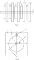
- Figures 1 and 2 are the front view and side view, respectively, of a direct reading water meter comprising a dual x axis magnetoresistive angle sensor or dual z axis magnetoresistive angle sensor, wherein the biaxial magnetoresistive angle sensor 2 comprises dual x axis magnetoresistive angle sensor chips or dual z axis magnetoresistive sensor chips 21 and 22, and a plurality of hard magnetic rotating wheels 1. There is a predetermined transmission ratio between the hard magnetic rotating wheels 1, and the hard magnetic rotating wheels 1 have a shared axis of rotation 4. In addition, it also comprises a PCB 3 on which the biaxial magnetoresistive angle sensor 2 is mounted.
- the hard magnetic rotating wheels 1 have a cylindrical structure, wherein dual x axis magnetoresistive angle sensor chips or dual z axis magnetoresistive sensor chips 21 and 22 are located beyond the side surface of the cylinder of the hard magnetic rotating wheel 1 or the plane of extension of the side surface of the cylinder. Their vertical distance from the side surface of the cylinder of the hard magnetic rotating wheel 1 of the permanent magnetic rotating wheel or from the plane of extension of the side surface of the cylinder is the same, and they are located at two positions spanning the round face at a 90 degree arc.
- the hard magnetic rotating wheels 1 have a magnetization direction 5 parallel to the diameter.
- the dual x axis magnetoresistive angle sensor chips or dual z axis magnetoresistive sensor chips have the same magnetic field sensitivity.
- Figures 3 and 4 are the front view and side view, respectively, of a direct reading water meter comprising a single chip Z-X biaxial magnetoresistive angle sensor, wherein 2(1) is the single chip Z-X biaxial magnetoresistive angle sensor, positioned above the circumference of the permanent magnetic rotating wheel 1.
- single chip Z-X biaxial magnetoresistive angle sensor 2(1) of this embodiment can be replaced by a Z axis magnetoresistive sensor chip and X axis magnetoresistive angle sensor chip in the same position.
- a separate chip diagram is not presented.
- the sensitive Z direction of the Z axis magnetoresistive sensor chip and single chip Z-X biaxial magnetoresistive angle sensor corresponds to the radial direction of the circumference of the hard magnetic rotating wheel at the position of the sensor chip.
- the sensitive direction of the X axis magnetoresistive sensor chip and the X axis magnetoresistive sensor of the single chip Z-X biaxial magnetoresistive angle sensor corresponds to the tangential direction of the circumference of the hard magnetic rotating wheel at the position of the sensor chip.
- Embodiment 1 and Embodiment 2 When the three types of biaxial magnetoresistive angle sensors of Embodiment 1 and Embodiment 2 are used in direct reading water meters, angle measurements of each permanent magnetic rotating wheel are separately conducted, the positions of the rotating wheels are determined, then using the predetermined transmission ratio relationship between the rotating wheels, the water meter's total number of revolutions is read out directly.
- the positional relationship between it and its corresponding permanent magnetic rotating wheels is as shown in Figure 2 .
- the angle of intersection between the X axis and the direction of magnetization intensity parallel to a straight line in the direction of the diameter is ⁇ , and it is used to represent the rotation angle.
- the magnetic fields at the location of the dual x axis magnetoresistive angle sensor chips or dual z axis magnetoresistive sensor chips 21 and 22 are (HX1, HZ1) and (HX2, HZ2), respectively.
- HX1 and HZ1 are the magnetic field components at position 21
- HX2 and HZ2 are the magnetic field components at position 22.
- the magnetic field measurement signals for the dual x axis magnetoresistive sensors areHX2 and HZ1, respectively.
- a typical relationship curve between measured magnetic field and rotation angle and the output signals for two measured magnetic fields are shown in Figures 5 and 6 , respectively.
- the curve 200 has a typical linear relationship, and the two sensors' measured magnetic field signals are as shown in curves 201 and 202, respectively.
- the two feature typical sine/cosine curve characteristics, and the phase difference is approximately 90 degrees. Therefore, it is entirely suitable to use a biaxial magnetoresistive angle sensor to measure hard magnetic rotating wheels, and thus design a read-only water meter comprising a biaxial magnetoresistive angle sensor.
- the substrate spacing of the Z axis magnetoresistive sensor or Z axis magnetoresistive sensor unit and Z axis magnetoresistive sensor or X axis magnetoresistive sensor unit on a single chip Z-X biaxial magnetoresistive angle sensor it is necessary to consider the magnetic interference among the plurality of hard magnetic rotating wheels for optimization, to ensure that the biaxial angle sensor is located in the linear operation region of the correlation between magnetic field angle and rotating wheel rotation angle.
- a key issue is that of magnetic field interference among the plurality of hard magnetic rotating wheels, with regard to the multiple hard magnetic rotating wheel structure of a water meter.
- Soft magnetic materials are commonly used for magnetic field shielding of the hard magnetic rotating wheels, to reduce the magnetic field interference between adjacent hard magnetic rotating wheels.
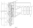
- Figure 7 is the signal processing circuit diagram of the automatic magnetic flow recording device. It uses 3 hard magnetic rotating wheels as an example to give an explanation, and it is similarly applicable to other numbers of hard magnetic rotating wheels. 17, 18, and 19 are the biaxial magnetoresistive angle sensors corresponding to hard magnetic rotating wheels 31, 32 and 33. In the present embodiment, the hypothetical situation is that any given biaxial magnetoresistive angle sensor comprises a single-axis magnetoresistive angle sensor with a two full-bridge structure; it is similarly applicable to other types, such as single-axis angle sensors with a half bridge or quasi-bridge structure.
- the power source output terminals of the biaxial magnetoresistive angle sensors 17, 18 or 19 are connected to the battery 10 through a SWO in the switch selection circuit 16. Only when a biaxial magnetoresistive angle sensor is in operating mode is its power source signal terminal connected; when it is not in operating mode, the power source is in off-mode, to conserve power.
- the signal output terminals of the biaxial magnetoresistive angle sensors are connected to the signal amplifiers 15 and 14 through SW1, SW2, SW3, and SW4 of the switch selection circuit 16, respectively.
- the output signal terminals of its two corresponding single-axis linear magnetoresistive sensors are connected by the switch selection circuit 16; thus, each is able to enter a signal amplifier.
- the signal amplifier is a differential signal amplifier; in half bridge structure, it is a single input signal amplifier.
- each hard magnetic rotating wheel has a numerical scale of 0-10 along the round face, 360 degrees are equally divided into 10 parts, and each arc corresponds to 36 degrees.
- the microprocessor Based on the rotation angle recorded by the corresponding biaxial magnetoresistive angle sensor, the microprocessor goes on to calculate the numerical scale corresponding to this hard magnetic rotating wheel. After separately reading the signal for each permanent magnetic rotating wheel, the total number of revolutions is acquired. MCU microprocessor 12 outputs the calculated information through the I/O module 11.
- the I/O module can be either an electronic circuit system, near field communication system, or radio frequency system.
- the battery 10 provides the switch circuit 16 and signal amplifiers 15 and 14, as well as the A-D converter 13, MCU microprocessor 12, and I/O module 11 with a power source .
- a direct reading water meter is used as an example to give an explanation.
- the present invention applies to various liquid or gas direct reading measurements and their displays.
- the hard magnetic rotating wheels of the present invention's automatic magnetic flow recording device correspond to at least one biaxial magnetoresistive angle sensor, and the biaxial magnetoresistive angle sensor comprises at least two single-axis linear magnetoresistive sensors.
- the biaxial magnetoresistive angle sensor comprises at least two single-axis linear magnetoresistive sensors.
Landscapes
- Physics & Mathematics (AREA)
- General Physics & Mathematics (AREA)
- Condensed Matter Physics & Semiconductors (AREA)
- Fluid Mechanics (AREA)
- Engineering & Computer Science (AREA)
- Computer Hardware Design (AREA)
- Measuring Volume Flow (AREA)
- Transmission And Conversion Of Sensor Element Output (AREA)
- Details Of Flowmeters (AREA)
- Measurement Of Length, Angles, Or The Like Using Electric Or Magnetic Means (AREA)
Applications Claiming Priority (2)
| Application Number | Priority Date | Filing Date | Title |
|---|---|---|---|
| CN201510058471.2A CN104596605B (zh) | 2015-02-04 | 2015-02-04 | 一种磁自动化流量记录器 |
| PCT/CN2016/073175 WO2016124131A1 (zh) | 2015-02-04 | 2016-02-02 | 一种磁自动化流量记录器 |
Publications (2)
| Publication Number | Publication Date |
|---|---|
| EP3255391A1 true EP3255391A1 (de) | 2017-12-13 |
| EP3255391A4 EP3255391A4 (de) | 2018-11-21 |
Family
ID=53122538
Family Applications (1)
| Application Number | Title | Priority Date | Filing Date |
|---|---|---|---|
| EP16746126.8A Withdrawn EP3255391A4 (de) | 2015-02-04 | 2016-02-02 | Aufzeichnungsgerät für magnetischen automatisierungsdurchfluss |
Country Status (5)
| Country | Link |
|---|---|
| US (1) | US11636889B2 (de) |
| EP (1) | EP3255391A4 (de) |
| JP (1) | JP6806689B2 (de) |
| CN (1) | CN104596605B (de) |
| WO (1) | WO2016124131A1 (de) |
Families Citing this family (2)
| Publication number | Priority date | Publication date | Assignee | Title |
|---|---|---|---|---|
| CN104596605B (zh) | 2015-02-04 | 2019-04-26 | 江苏多维科技有限公司 | 一种磁自动化流量记录器 |
| CN105203172A (zh) * | 2015-07-20 | 2015-12-30 | 谈晓彬 | 一种液封水表电子直读字轮盒 |
Family Cites Families (47)
| Publication number | Priority date | Publication date | Assignee | Title |
|---|---|---|---|---|
| DE19538163C1 (de) * | 1995-10-13 | 1997-03-27 | Wehrle E Gmbh | Vorrichtung zur Drehzahl- und Drehrichtungserkennung mittels magnetfeldabhängiger Widerstandselemente |
| JP3726418B2 (ja) * | 1997-04-18 | 2005-12-14 | 株式会社デンソー | 回転検出装置 |
| JP3609645B2 (ja) | 1999-03-11 | 2005-01-12 | 株式会社東海理化電機製作所 | 回転検出センサ |
| JP3872262B2 (ja) * | 2000-01-25 | 2007-01-24 | セイコーインスツル株式会社 | 電子方位計及び電子方位計付電子時計 |
| US6604434B1 (en) * | 2000-06-23 | 2003-08-12 | Neptune Technology Group, Inc. | Method and apparatus for determining the direction and rate of a rotating element |
| US6819292B2 (en) * | 2001-03-09 | 2004-11-16 | Arad Measuring Technologies Ltd | Meter register |
| JP2003075108A (ja) | 2001-09-04 | 2003-03-12 | Asahi Kasei Corp | 回転角度センサ |
| JP2003202224A (ja) * | 2001-12-28 | 2003-07-18 | Niles Parts Co Ltd | 回転角検出装置 |
| US7307415B2 (en) * | 2002-02-14 | 2007-12-11 | Bvr Technologies Co. | Contactless angular position sensor and method for sensing angular position of a rotatable shaft |
| US7036372B2 (en) | 2003-09-25 | 2006-05-02 | Kionix, Inc. | Z-axis angular rate sensor |
| JP4470577B2 (ja) | 2004-05-14 | 2010-06-02 | 株式会社デンソー | 回転角度検出装置 |
| TWI361503B (en) | 2005-03-17 | 2012-04-01 | Yamaha Corp | Three-axis magnetic sensor and manufacturing method therefor |
| JP4950713B2 (ja) | 2007-03-20 | 2012-06-13 | オークマ株式会社 | アブソリュートエンコーダ |
| JP5592270B2 (ja) | 2008-01-04 | 2014-09-17 | アレグロ・マイクロシステムズ・エルエルシー | 角度センサのための方法および装置 |
| US9823090B2 (en) * | 2014-10-31 | 2017-11-21 | Allegro Microsystems, Llc | Magnetic field sensor for sensing a movement of a target object |
| CN101629802A (zh) | 2008-07-14 | 2010-01-20 | Tdk株式会社 | 角度检测装置和角度检测方法 |
| US8587295B2 (en) * | 2009-02-26 | 2013-11-19 | Hitachi Metals, Ltd. | Angle detection apparatus and position detection apparatus |
| JP5287635B2 (ja) | 2009-09-24 | 2013-09-11 | 株式会社ジェイテクト | 回転角センサ、モータ、回転角検出装置、及び電動パワーステアリング装置 |
| IT1403421B1 (it) | 2010-12-23 | 2013-10-17 | St Microelectronics Srl | Sensore magnetoresistivo integrato, in particolare sensore magnetoresistivo triassiale e suo procedimento di fabbricazione |
| CN102297652B (zh) | 2011-03-03 | 2012-12-05 | 江苏多维科技有限公司 | 一种独立封装的磁电阻角度传感器 |
| CN202119390U (zh) | 2011-03-03 | 2012-01-18 | 江苏多维科技有限公司 | 一种独立封装的桥式磁场角度传感器 |
| CN102226835A (zh) * | 2011-04-06 | 2011-10-26 | 江苏多维科技有限公司 | 单一芯片双轴磁场传感器及其制备方法 |
| US20130010641A1 (en) | 2011-07-05 | 2013-01-10 | Esmael Dinan | Carrier Activation Employing RRC messages |
| CN102385043B (zh) | 2011-08-30 | 2013-08-21 | 江苏多维科技有限公司 | Mtj三轴磁场传感器及其封装方法 |
| CN102419425B (zh) | 2011-09-09 | 2013-12-04 | 兰州大学 | 一种磁电阻自动测量装置及其测量方法 |
| US8947082B2 (en) | 2011-10-21 | 2015-02-03 | University College Cork, National University Of Ireland | Dual-axis anisotropic magnetoresistive sensors |
| US20130116941A1 (en) * | 2011-11-04 | 2013-05-09 | Watersignal, Llc | Fluid pipe monitoring and reporting system |
| CN102628703B (zh) * | 2012-03-01 | 2017-05-24 | 陈健 | 计量表电子直读计数器 |
| US8952683B2 (en) * | 2012-07-25 | 2015-02-10 | Infineon Technologies Ag | Magnetic out-of-axis angle sensing principle |
| CN202974369U (zh) * | 2012-08-24 | 2013-06-05 | 江苏多维科技有限公司 | 直读式计量装置和直读式水表 |
| CN103915233B (zh) * | 2013-01-05 | 2017-02-08 | 江苏多维科技有限公司 | 一种适用于角度磁编码器的永磁体 |
| JP6056482B2 (ja) * | 2013-01-08 | 2017-01-11 | 株式会社ジェイテクト | 回転角センサの異常検出装置 |
| CN203116756U (zh) * | 2013-01-09 | 2013-08-07 | 江苏多维科技有限公司 | 一种角度磁编码器和电子水表 |
| CN103913183A (zh) | 2013-01-09 | 2014-07-09 | 江苏多维科技有限公司 | 一种角度磁编码器和电子水表 |
| CN103925933B (zh) * | 2013-01-11 | 2016-12-28 | 江苏多维科技有限公司 | 一种多圈绝对磁编码器 |
| CN103968860B (zh) * | 2013-02-01 | 2017-07-04 | 江苏多维科技有限公司 | 绝对式磁旋转编码器 |
| WO2014197883A1 (en) * | 2013-06-06 | 2014-12-11 | Transparent Technologies Inc. | Wireless utility metering devices, systems, and methods |
| TWI493209B (zh) * | 2013-07-05 | 2015-07-21 | Voltafield Technology Corp | 一種單晶片三軸磁阻感測裝置 |
| CN103901363B (zh) | 2013-09-10 | 2017-03-15 | 江苏多维科技有限公司 | 一种单芯片z轴线性磁电阻传感器 |
| CN203704997U (zh) * | 2014-03-05 | 2014-07-09 | 成都千嘉科技有限公司 | 一种磁电直读计量装置 |
| CN204007758U (zh) * | 2014-07-31 | 2014-12-10 | 株式会社村田制作所 | 流量检测器 |
| CN104197827B (zh) | 2014-08-18 | 2017-05-10 | 江苏多维科技有限公司 | 一种双z轴磁电阻角度传感器 |
| CN204043603U (zh) * | 2014-08-18 | 2014-12-24 | 江苏多维科技有限公司 | 一种双z轴磁电阻角度传感器 |
| CN204043604U (zh) * | 2014-08-20 | 2014-12-24 | 江苏多维科技有限公司 | 一种单芯片偏轴磁电阻z-x角度传感器和测量仪 |
| CN104197828B (zh) | 2014-08-20 | 2017-07-07 | 江苏多维科技有限公司 | 一种单芯片偏轴磁电阻z‑x角度传感器和测量仪 |
| CN204535800U (zh) * | 2015-02-04 | 2015-08-05 | 江苏多维科技有限公司 | 一种磁自动化流量记录器 |
| CN104596605B (zh) * | 2015-02-04 | 2019-04-26 | 江苏多维科技有限公司 | 一种磁自动化流量记录器 |
-
2015
- 2015-02-04 CN CN201510058471.2A patent/CN104596605B/zh active Active
-
2016
- 2016-02-02 US US15/549,108 patent/US11636889B2/en active Active
- 2016-02-02 WO PCT/CN2016/073175 patent/WO2016124131A1/zh not_active Ceased
- 2016-02-02 JP JP2017541011A patent/JP6806689B2/ja active Active
- 2016-02-02 EP EP16746126.8A patent/EP3255391A4/de not_active Withdrawn
Also Published As
| Publication number | Publication date |
|---|---|
| JP6806689B2 (ja) | 2021-01-06 |
| CN104596605A (zh) | 2015-05-06 |
| JP2018508769A (ja) | 2018-03-29 |
| US20180033474A1 (en) | 2018-02-01 |
| EP3255391A4 (de) | 2018-11-21 |
| CN104596605B (zh) | 2019-04-26 |
| WO2016124131A1 (zh) | 2016-08-11 |
| US11636889B2 (en) | 2023-04-25 |
Similar Documents
| Publication | Publication Date | Title |
|---|---|---|
| CN112414297B (zh) | 磁传感器设备、系统和方法 | |
| EP3184954B1 (de) | Magnetoresistiver winkelsensor | |
| US8664943B2 (en) | Position detecting apparatus | |
| CN102141371B (zh) | 用于确定传感器装置和磁场之间角度的角度传感器和方法 | |
| US8604780B2 (en) | Rotating field sensor | |
| US8265897B2 (en) | Rotation angle detector and process for detecting rotation angle | |
| US20150022186A1 (en) | Angle sensors, systems and methods | |
| US20120038359A1 (en) | Rotating field sensor | |
| JPH0989595A (ja) | ロータリーエンコーダ | |
| US9903741B2 (en) | Magnetic position sensor and sensing method | |
| CN103472414A (zh) | 磁传感器装置 | |
| EP1582754B1 (de) | Lageranordnung mit einem Magnetfeldsensor | |
| CN116379899B (zh) | 具有误差检测的磁位置传感器设备、方法和系统 | |
| US12352606B2 (en) | Magnetic position sensor system, method and device with error detection | |
| US20210072044A1 (en) | Output system and gauge | |
| US20160327413A1 (en) | Nonvolatile Rotation Sensor With Spiral Track | |
| EP3255391A1 (de) | Aufzeichnungsgerät für magnetischen automatisierungsdurchfluss | |
| CN110044252A (zh) | 一种用于检测轴转动角度的测量装置及测量方法 | |
| CN111928871B (zh) | 精密磁霍尔里程计 | |
| CN116379898B (zh) | 具有误差检测的磁位置传感器设备、方法和系统 | |
| KR101427218B1 (ko) | 전자기유도 방식을 이용한 각도센서 및 이를 이용한 가동물체의 회전각도 측정시스템 | |
| US7400265B2 (en) | Remotely readable gas meter and method of using the same | |
| CN204535800U (zh) | 一种磁自动化流量记录器 | |
| GB2321969A (en) | Rotary coupling alignment | |
| KR102744484B1 (ko) | 자기장 센서를 이용한 전자식 수도미터기의 외부자력 측정방법 |
Legal Events
| Date | Code | Title | Description |
|---|---|---|---|
| PUAI | Public reference made under article 153(3) epc to a published international application that has entered the european phase |
Free format text: ORIGINAL CODE: 0009012 |
|
| 17P | Request for examination filed |
Effective date: 20170901 |
|
| AK | Designated contracting states |
Kind code of ref document: A1 Designated state(s): AL AT BE BG CH CY CZ DE DK EE ES FI FR GB GR HR HU IE IS IT LI LT LU LV MC MK MT NL NO PL PT RO RS SE SI SK SM TR |
|
| AX | Request for extension of the european patent |
Extension state: BA ME |
|
| DAV | Request for validation of the european patent (deleted) | ||
| DAX | Request for extension of the european patent (deleted) | ||
| A4 | Supplementary search report drawn up and despatched |
Effective date: 20181022 |
|
| RIC1 | Information provided on ipc code assigned before grant |
Ipc: G01D 5/14 20060101ALI20181012BHEP Ipc: G01B 7/30 20060101ALI20181012BHEP Ipc: G01F 15/06 20060101AFI20181012BHEP Ipc: G01R 33/09 20060101ALI20181012BHEP |
|
| 17Q | First examination report despatched |
Effective date: 20190726 |
|
| STAA | Information on the status of an ep patent application or granted ep patent |
Free format text: STATUS: THE APPLICATION HAS BEEN WITHDRAWN |
|
| 18W | Application withdrawn |
Effective date: 20200204 |