EP3255447A1 - Dispositif et système et noeud de positionnement de rayons infrarouges - Google Patents
Dispositif et système et noeud de positionnement de rayons infrarouges Download PDFInfo
- Publication number
- EP3255447A1 EP3255447A1 EP16746059.1A EP16746059A EP3255447A1 EP 3255447 A1 EP3255447 A1 EP 3255447A1 EP 16746059 A EP16746059 A EP 16746059A EP 3255447 A1 EP3255447 A1 EP 3255447A1
- Authority
- EP
- European Patent Office
- Prior art keywords
- infrared ray
- reflection
- positioning node
- emitting tube
- included angle
- Prior art date
- Legal status (The legal status is an assumption and is not a legal conclusion. Google has not performed a legal analysis and makes no representation as to the accuracy of the status listed.)
- Withdrawn
Links
Images



Classifications
-
- G—PHYSICS
- G01—MEASURING; TESTING
- G01S—RADIO DIRECTION-FINDING; RADIO NAVIGATION; DETERMINING DISTANCE OR VELOCITY BY USE OF RADIO WAVES; LOCATING OR PRESENCE-DETECTING BY USE OF THE REFLECTION OR RERADIATION OF RADIO WAVES; ANALOGOUS ARRANGEMENTS USING OTHER WAVES
- G01S5/00—Position-fixing by co-ordinating two or more direction or position line determinations; Position-fixing by co-ordinating two or more distance determinations
- G01S5/16—Position-fixing by co-ordinating two or more direction or position line determinations; Position-fixing by co-ordinating two or more distance determinations using electromagnetic waves other than radio waves
-
- G—PHYSICS
- G01—MEASURING; TESTING
- G01S—RADIO DIRECTION-FINDING; RADIO NAVIGATION; DETERMINING DISTANCE OR VELOCITY BY USE OF RADIO WAVES; LOCATING OR PRESENCE-DETECTING BY USE OF THE REFLECTION OR RERADIATION OF RADIO WAVES; ANALOGOUS ARRANGEMENTS USING OTHER WAVES
- G01S1/00—Beacons or beacon systems transmitting signals having a characteristic or characteristics capable of being detected by non-directional receivers and defining directions, positions, or position lines fixed relatively to the beacon transmitters; Receivers co-operating therewith
- G01S1/70—Beacons or beacon systems transmitting signals having a characteristic or characteristics capable of being detected by non-directional receivers and defining directions, positions, or position lines fixed relatively to the beacon transmitters; Receivers co-operating therewith using electromagnetic waves other than radio waves
-
- G—PHYSICS
- G01—MEASURING; TESTING
- G01S—RADIO DIRECTION-FINDING; RADIO NAVIGATION; DETERMINING DISTANCE OR VELOCITY BY USE OF RADIO WAVES; LOCATING OR PRESENCE-DETECTING BY USE OF THE REFLECTION OR RERADIATION OF RADIO WAVES; ANALOGOUS ARRANGEMENTS USING OTHER WAVES
- G01S1/00—Beacons or beacon systems transmitting signals having a characteristic or characteristics capable of being detected by non-directional receivers and defining directions, positions, or position lines fixed relatively to the beacon transmitters; Receivers co-operating therewith
- G01S1/70—Beacons or beacon systems transmitting signals having a characteristic or characteristics capable of being detected by non-directional receivers and defining directions, positions, or position lines fixed relatively to the beacon transmitters; Receivers co-operating therewith using electromagnetic waves other than radio waves
- G01S1/703—Details
- G01S1/7032—Transmitters
- G01S1/7034—Mounting or deployment thereof
-
- G—PHYSICS
- G01—MEASURING; TESTING
- G01S—RADIO DIRECTION-FINDING; RADIO NAVIGATION; DETERMINING DISTANCE OR VELOCITY BY USE OF RADIO WAVES; LOCATING OR PRESENCE-DETECTING BY USE OF THE REFLECTION OR RERADIATION OF RADIO WAVES; ANALOGOUS ARRANGEMENTS USING OTHER WAVES
- G01S1/00—Beacons or beacon systems transmitting signals having a characteristic or characteristics capable of being detected by non-directional receivers and defining directions, positions, or position lines fixed relatively to the beacon transmitters; Receivers co-operating therewith
- G01S1/70—Beacons or beacon systems transmitting signals having a characteristic or characteristics capable of being detected by non-directional receivers and defining directions, positions, or position lines fixed relatively to the beacon transmitters; Receivers co-operating therewith using electromagnetic waves other than radio waves
- G01S1/703—Details
- G01S1/7032—Transmitters
- G01S1/7038—Signal details
-
- G—PHYSICS
- G01—MEASURING; TESTING
- G01S—RADIO DIRECTION-FINDING; RADIO NAVIGATION; DETERMINING DISTANCE OR VELOCITY BY USE OF RADIO WAVES; LOCATING OR PRESENCE-DETECTING BY USE OF THE REFLECTION OR RERADIATION OF RADIO WAVES; ANALOGOUS ARRANGEMENTS USING OTHER WAVES
- G01S2201/00—Indexing scheme relating to beacons or beacon systems transmitting signals capable of being detected by non-directional receivers and defining directions, positions, or position lines fixed relatively to the beacon transmitters
- G01S2201/01—Indexing scheme relating to beacons or beacon systems transmitting signals capable of being detected by non-directional receivers and defining directions, positions, or position lines fixed relatively to the beacon transmitters adapted for specific applications or environments
Definitions
- the present invention relates to a wireless signal emitting device and system and in particular to an infrared ray positioning node device and system.
- a wireless network technologies it is desirous to identify an object and perform precise positioning with wireless signals. For example, in an environment such as an airport which passengers gather in and are unfamiliar with, a convenient and precise positioning is much more needed.
- Indoor positioning in the prior art usually performs ID identification on a target object by a positioning node device emitting wireless signals.
- An ideal state is that one positioning node corresponds to one ID.
- a currently widely used node positioning device usually includes a signal emission tube and a circuit board. For example, signals emitted by the ID identification device described in Chinese patent No.
- Fig. 1 is a view of an infrared ray projection region of a traditional infrared ray positioning node device. Node positioning devices A and B are both suspended over the ceiling and form a conic infrared ray projection area respectively. As shown in Fig. 1 , a relatively large signal blind area is formed between the infrared ray projection areas of positioning nodes A and B.
- An object of the present invention is to provide an infrared ray positioning node device and system which is capable of providing stable signals, uniform signal intensity and good signal directivity.
- an infrared ray positioning node device comprising: a reflection cup with a plurality of side surfaces; and an infrared ray emitting tube cooperating with the reflection cup and being positioned so that the range of an included angle m formed after rays emitted by the infrared ray emitting tube reflect off some reflection side surfaces in the plurality of side surfaces is 0° ⁇ m ⁇ 180°.
- an infrared ray positioning node system comprising a plurality of infrared ray positioning node devices which are configured so that the infrared ray emitting directions of some infrared ray positioning node devices s are perpendicular to those of the remaining infrared ray positioning node devices.
- the range of the infrared ray emitting signal is controllable within a range from 0° to 180°, so that the emitted signal is stable and has uniform intensity.
- the radiation utilization of the infrared ray emitting tube is improved and the power consumption of the node device is reduced. Uniform projection of the infrared light can be realized which effectively avoids blind areas of emission of a single node and signal interference between adjacent nodes.
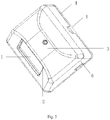
- Fig. 2 schematically shows an infrared ray positioning node device according to an embodiment of the present invention.
- the device includes a reflection cup 1 (the main body structure thereof is located in a housing), an infrared ray emitting tube 2, a central control point 3, a housing 4, a power interface 5 and an upgrade interface 6.
- the central control point 3 may be a circuit board integrated with a power source, a microprocessor, a wireless module and a photosensitive element. It can be used to provide power supply to the infrared ray positioning node device, receive signals , process signals, and send signals (such as infrared ray signals) to the infrared ray positioning node device.
- the power source is connected to the power interface 6.
- the power source supplies power to the infrared ray positioning node device.
- the microprocessor is connected to the upgrade interface 6.
- the microprocessor processes the received signals and may upgrade a program, so that communication and data upgrade may be performed through infrared ray signals, which increases the utility performance, convenience and functionality of the device.
- the central control point 3 is provided with a light hole providing light to the photosensitive element.
- the photosensitive element senses the ambient light through the light hole and automatically adjusts the intensity of the infrared ray emitted by the infrared ray emitting tube 2, improving the radiation utilization of the infrared ray emitting tube and reducing the power consumption of the infrared ray positioning node device.
- the housing 4 may be of a box shape (and may also be other shapes suitable for fabricating) to accommodate the reflection cup 1, the infrared ray emitting tub 2 and the central control point 3 and is left with a groove matching with the power interface 5 and the upgrade interface 6 and a rectangular opening matching with the reflection cup 1.
- the housing 4 is provided with groove positions or small holes for installing the reflection cup 1 at different angles.
- the reflection cup 1 has a function of reflecting infrared rays, and the unique structure of which can make the reflected infrared ray projected uniformly in a space of 0° ⁇ X ⁇ 180°.
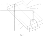
- Fig. 3 shows the structure of a reflection cup 1 according to an embodiment of the present invention.
- the shape of the reflection cup 1 is a cuboid (a parallel hexahedron with its side edges being perpendicular to its bottom surface) which includes an upper bottom surface 15, a lower bottom surface 16, a first reflection side surface 11, a second reflection side surface 12, a third transmitting side surface 13, a fourth side surface 14 and an infrared ray emitting tube 2.
- the upper bottom surface 15 may be of a parallelogram shape.
- the lower bottom surface 16 may also be of a parallelogram shape.
- the first reflection side surface 11 and the second reflection side surface 12 which are adjacent to each other may form a first included angle ⁇ .
- the third transmitting side surface 13 may be of a rectangular shape and may be opposite to the first reflection side surface 11 and adjacent to the second reflection side surface 12.
- the fourth side surface 14 may be of a rectangular shape and may be adjacent to the first reflection side surface 11 and the third transmitting side surface 13 respectively.
- the radiation range of the infrared ray emitting tube 2 for matching with the reflection cup 1 is determined by a second included angle ⁇ formed by a first edge ray and a second edge ray.
- the reflected infrared ray is uniformly projected in a space of 0° ⁇ X ⁇ 180°.
- the reflected infrared ray can be projected uniformly in a space of 90°, forming a rectangular parallelepiped infrared light beam:
- the reflection cup When the reflection cup is configured in the above manner, the first reflection light ray and the second reflection light ray formed after the first edge light ray and the second edge light ray are reflected by the first reflection side surface and the second reflection side surface form a rectangular parallelepiped infrared light beam with an angle of 90°.
- the structure of the above infrared ray positioning node device makes the projected infrared light beam rectangular parallelepiped, reducing signal blind areas and making signal intensity even and stable.
- this embodiment adopts one infrared ray emitting tube to schematically reflect the light ray refraction effect.
- a plurality of infrared ray emitting tubs may be provided in the housing, which may be in particular provided on the upper portion, the lower portion or the inner side of the reflection cup.
- the direction of the infrared ray emitting signal is controllable, the signal is stable and intensity thereof is uniform, the radiation utilization of the infrared ray emitting tube is improved, the power consumption of the node device can be reduced, a uniform projection of infrared light can be realized, and emission blind areas of a single node and signal interference between adjacent nodes can be effectively avoided.
- the shape of the reflection cup 1 is a cuboid including an upper bottom surface 15 of a parallelogram shape, a lower bottom surface 16 of a parallelogram shape and a fourth side surface 14 of a rectangle shape which adjoins the first reflection side surface 11 and the third transmitting side surface 13 respectively.
- Such a design is simple and convenient to process.
- the upper bottom surface 15, the lower bottom surface 16 and the fourth side surface 14 are coated with a light absorption material.
- At least one hole for accommodating the infrared ray emitting tube is provided on the fourth side surface 14 or on the lower bottom surface 16 adjacent to the fourth side surface 14.
- the bulbs of the infrared ray emitting tube are installed in the corresponding holes of size and number matching therewith.
- the structure of the above infrared ray positioning node device makes the infrared ray emitting tube directly radiate the reflection surface with few infrared ray dispersion losses and good reflection effect.
- both the upper bottom surface 15 and the fourth side surface 14 are light absorption surfaces
- the lower bottom surface 16 is a transmitting surface
- the outside of the reflection cup is a central control point
- the infrared ray emitting tube is connected to the central control point and located underneath the lower bottom surface 16.
- the upper bottom surface 15 and the lower bottom surface 16 are both light absorption surfaces
- the fourth side surface 14 is a transmitting surface
- the infrared ray emitting tube is connected to the central control point and located outside the fourth side surface.
- the infrared ray emitting tube is installed outside the reflection cup without piercing the reflection cup, which is not only simple in fabricating but also convenient for installation.
- the main body of the reflection cup is a solid structure made of a transmitting material.
- a structure makes it convenient to coat a light absorption or reflection material on various side surfaces as desired, which not only makes the processing simple but also reliable in quality.
- the infrared ray emitting tube is installed outside the reflection cup, for example, installed on the upper portion, the lower portion of the reflection cup or the outside of the fourth side surface, which merely requires to change the light absorption material or transmitting material accordingly, so that the incidence surface of the infrared ray emitted by the infrared ray emitting tube and the third rectangular transmitting side surface 13 of the reflection cup from which the infrared ray is reflected are of a transmitting material, the first reflection surface 11 and the second reflection surface 12 are of a reflection material, and the other surfaces are of a light absorption material.
- the infrared ray positioning node device in the present invention is designed to have a box shape, which makes it more convenient for installation.
- An infrared ray positioning node system consisting of a plurality of infrared ray positioning node devices brings up different technical effects through different installation methods during installation.
- the infrared ray emitted from some infrared ray positioning node devices is perpendicular to that from the remaining infrared ray positioning node devices.
- a distance between each of some infrared ray positioning node devices is set so that no overlapped radiation region exists among these infrared ray positioning node devices, and a distance between each of the remaining infrared ray positioning node devices is set so that no overlapped radiation region exists among the remaining infrared ray positioning node devices.
- the above illustrated hexahedron reflection cup merely schematically illustrates an effect of the infrared ray incidence and reflection, while the calculation of various angles are relatively simple.
- various changes may be made to the shape of the reflection cup.
- the upper bottom surface and the lower bottom surface are configured as trapezoid or pentagon and the like.
- There may be a plurality of side surfaces, as long as the following requirements are satisfied: after the light rays emitted by the infrared ray emitting tube are reflected by some reflection side surfaces in the plurality of side surface, the range of an included angle m formed between the reflected rays from different reflection side surfaces is 0° ⁇ m ⁇ 180°.
- the plurality of side surfaces of the reflection cup may include: a first reflection side surface and a second reflection side surface adjacent to each other and forming a first included angle ⁇ ; and a third transmitting side surface opposite to the first reflection side surface and adjacent to the second reflection side surface.
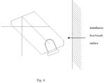
- Figs. 4 to 7 schematically show some typical installation methods of an infrared ray positioning node device (or system).
- Fig. 4 shows an infrared ray positioning node device being installed on a vertical benchmark surface.
- Fig. 5 shows a perspective view of the installation method in Fig. 4 .
- an infrared ray positioning node system (including infrared ray positioning node devices A and B) is installed on an indoor wall (such as a waiting room of an airport).
- the infrared ray positioning node devices A and B form perspective infrared ray signal projection areas in the waiting room of the airport respectively which form rectangular projection sections on the wall and the floor respectively.
- the infrared ray positioning node devices A and B may also communicate information with each other through the microprocessors and wireless modules therein so that these devices are more powerful and more convenient in use.
- large-span positioning and identification can be realized by installing several nodes. That is, the projection width d in the figure is controlled by changing the number of nodes.
- the signal intensity may be uniform and the receiving may be stable and reliable, reducing signal blind areas significantly in the emission range.
- the infrared ray positioning node devices A and B are arranged in parallel, which can save the number of infrared ray positioning node devices.
- the infrared ray emitted from some infrared ray positioning node devices is perpendicular to that from the remaining infrared ray positioning node devices.
- a distance between each of some infrared ray positioning node devices is set so that no overlapped radiation region exists among these infrared ray positioning node devices, and a distance between each of the remaining infrared ray positioning node devices is set so that no overlapped radiation region exists among the remaining infrared ray positioning node devices.
- the reflection cup has a function of reflecting infrared rays.
- the unique structure thereof can make the emitted infrared light projected uniformly in space.
- the housing of the nodes has a groove position for the best installation angle of the reflection cup.
- the section of the infrared light emitted from the node is rectangular, that is, having infrared light radiation in horizontal forward and vertical downward range, uniform intensity, stable and reliable receiving, so that the signal reception has no blind area in the emission range.
- the photosensitive element in the node can automatically adjust the intensity of the emitted infrared light by sensing the ambient light.
- Fig. 6 shows an infrared ray positioning node device being installed on a horizontal benchmark surface. For example, it is installed on the ceiling or floor of a waiting room of an airport. Due to the special design of the reflection cup and light-emitting opening of the infrared ray positioning node device in the present invention, the emitted infrared ray has a rectangular section, that is, having infrared light radiation in horizontal forward and vertical downward range, uniform intensity, stable and reliable receiving, so that the signal blind area is reduced to the greatest extent in the infrared ray radiation emission range.
- Fig. 7 shows a hybrid installation method based on two installation methods shown in Figs. 4 and 6 , that is, a vertical and horizontal hybrid installation method.
- a vertical and horizontal hybrid installation method As shown in Fig. 7 , by means of such a vertical and horizontal hybrid installation method, in addition to a very good reception effect of a single infrared ray positioning node device, signal blind area hardly exists, thus forming an infrared ray projection area with uniform infrared ray intensity covered by a rectangular section with the signal blind area completely eliminated in the projection area.
Landscapes
- Physics & Mathematics (AREA)
- Engineering & Computer Science (AREA)
- Electromagnetism (AREA)
- General Physics & Mathematics (AREA)
- Radar, Positioning & Navigation (AREA)
- Remote Sensing (AREA)
- Computer Networks & Wireless Communication (AREA)
- Optical Communication System (AREA)
- Geophysics And Detection Of Objects (AREA)
Applications Claiming Priority (2)
| Application Number | Priority Date | Filing Date | Title |
|---|---|---|---|
| CN201520086232.3U CN204462375U (zh) | 2015-02-06 | 2015-02-06 | 红外线定位节点装置及系统 |
| PCT/CN2016/070465 WO2016124064A1 (fr) | 2015-02-06 | 2016-01-08 | Dispositif et système et nœud de positionnement de rayons infrarouges |
Publications (2)
| Publication Number | Publication Date |
|---|---|
| EP3255447A1 true EP3255447A1 (fr) | 2017-12-13 |
| EP3255447A4 EP3255447A4 (fr) | 2018-10-17 |
Family
ID=53669243
Family Applications (1)
| Application Number | Title | Priority Date | Filing Date |
|---|---|---|---|
| EP16746059.1A Withdrawn EP3255447A4 (fr) | 2015-02-06 | 2016-01-08 | Dispositif et système et noeud de positionnement de rayons infrarouges |
Country Status (7)
| Country | Link |
|---|---|
| US (1) | US20180011166A1 (fr) |
| EP (1) | EP3255447A4 (fr) |
| JP (1) | JP2018511810A (fr) |
| KR (1) | KR20170105082A (fr) |
| CN (1) | CN204462375U (fr) |
| HK (1) | HK1248318A1 (fr) |
| WO (1) | WO2016124064A1 (fr) |
Cited By (1)
| Publication number | Priority date | Publication date | Assignee | Title |
|---|---|---|---|---|
| CN108594174A (zh) * | 2018-01-09 | 2018-09-28 | 河南大学 | 基于红外光色散的波长编码室内定位系统及方法 |
Families Citing this family (1)
| Publication number | Priority date | Publication date | Assignee | Title |
|---|---|---|---|---|
| CN204462375U (zh) * | 2015-02-06 | 2015-07-08 | 无锡知谷网络科技有限公司 | 红外线定位节点装置及系统 |
Family Cites Families (15)
| Publication number | Priority date | Publication date | Assignee | Title |
|---|---|---|---|---|
| US5990826A (en) * | 1997-10-07 | 1999-11-23 | Rockwell Science Center, Inc. | Interbuilding and urban canyon extension solution for global positioning systems |
| JP4170844B2 (ja) * | 2002-11-29 | 2008-10-22 | サンクス株式会社 | 除電装置 |
| US7204630B2 (en) * | 2004-06-30 | 2007-04-17 | 3M Innovative Properties Company | Phosphor based illumination system having a plurality of light guides and an interference reflector |
| DE602004025005D1 (de) * | 2004-11-15 | 2010-02-25 | Saab Ab | Sendeeinheit |
| US8651692B2 (en) * | 2009-06-18 | 2014-02-18 | Intematix Corporation | LED based lamp and light emitting signage |
| US8403530B2 (en) * | 2010-09-21 | 2013-03-26 | Honeywell International Inc. | LED spotlight including elliptical and parabolic reflectors |
| CN202153315U (zh) * | 2011-07-22 | 2012-02-29 | 无锡知谷网络科技有限公司 | 一种室内定位节点装置 |
| CN202361136U (zh) * | 2011-08-02 | 2012-08-01 | 吉永科技股份有限公司 | 照明装置 |
| US9279547B2 (en) * | 2012-01-13 | 2016-03-08 | Koninklijke Philips N.V. | LED-based direct-view luminaire with uniform lit appearance |
| US20140062774A1 (en) * | 2012-08-28 | 2014-03-06 | Disney Enterprises, Inc. | Performing seamless positioning using various location techniques |
| US10231782B2 (en) * | 2012-09-06 | 2019-03-19 | Covidien Lp | Medical devices and methods incorporating frustrated total internal reflection for energy-efficient sealing and cutting of tissue using light energy |
| WO2014138591A1 (fr) * | 2013-03-07 | 2014-09-12 | Quarkstar Llc | Dispositif d'éclairage comportant des éléments électroluminescents multicolores |
| WO2014172571A2 (fr) * | 2013-04-19 | 2014-10-23 | Quarkstar Llc | Dispositifs d'éclairage comportant des éléments optiques ajustables |
| CN104007412A (zh) * | 2014-06-05 | 2014-08-27 | 重庆广建装饰股份有限公司 | 基于led灯的室内定位系统 |
| CN204462375U (zh) * | 2015-02-06 | 2015-07-08 | 无锡知谷网络科技有限公司 | 红外线定位节点装置及系统 |
-
2015
- 2015-02-06 CN CN201520086232.3U patent/CN204462375U/zh not_active Expired - Lifetime
-
2016
- 2016-01-08 EP EP16746059.1A patent/EP3255447A4/fr not_active Withdrawn
- 2016-01-08 KR KR1020177022800A patent/KR20170105082A/ko not_active Ceased
- 2016-01-08 HK HK18107679.3A patent/HK1248318A1/en unknown
- 2016-01-08 JP JP2017559751A patent/JP2018511810A/ja active Pending
- 2016-01-08 US US15/547,127 patent/US20180011166A1/en not_active Abandoned
- 2016-01-08 WO PCT/CN2016/070465 patent/WO2016124064A1/fr not_active Ceased
Cited By (2)
| Publication number | Priority date | Publication date | Assignee | Title |
|---|---|---|---|---|
| CN108594174A (zh) * | 2018-01-09 | 2018-09-28 | 河南大学 | 基于红外光色散的波长编码室内定位系统及方法 |
| CN108594174B (zh) * | 2018-01-09 | 2022-02-01 | 河南大学 | 基于红外光色散的波长编码室内定位系统及方法 |
Also Published As
| Publication number | Publication date |
|---|---|
| EP3255447A4 (fr) | 2018-10-17 |
| US20180011166A1 (en) | 2018-01-11 |
| CN204462375U (zh) | 2015-07-08 |
| WO2016124064A1 (fr) | 2016-08-11 |
| JP2018511810A (ja) | 2018-04-26 |
| KR20170105082A (ko) | 2017-09-18 |
| HK1248318A1 (en) | 2018-10-12 |
Similar Documents
| Publication | Publication Date | Title |
|---|---|---|
| US9906080B2 (en) | Antenna configurations for wireless power and communication, and supplemental visual signals | |
| CN116075984B (zh) | 反射单元及无线传输系统 | |
| CN102683803B (zh) | 一种基于超材料卫星天线的商业液晶显示屏 | |
| US10454316B2 (en) | Antenna configurations for wireless power and communication, and supplemental visual signals | |
| US20110309987A1 (en) | Reflector antenna including radome | |
| US9666952B2 (en) | Antenna device | |
| US20150091673A1 (en) | Leaky feeder arrangement | |
| US20180011166A1 (en) | Infrared ray positining node device and system | |
| US20250309551A1 (en) | Radio transmission system | |
| CN111295595A (zh) | 信标网络、移动体定位系统以及物流管理系统 | |
| WO2022138397A1 (fr) | Plaque de réglage de phase, plaque de verre et système de communication sans fil | |
| AU2011298550A1 (en) | Method for designing uniform illumination reflector | |
| WO2023120471A1 (fr) | Condensateur d'ondes radio, vitre et système de communication par ondes radio | |
| TW201741683A (zh) | 無線定位裝置 | |
| JP6989033B2 (ja) | 電磁波フィルタおよび空間電磁界制御システム | |
| KR101608003B1 (ko) | 인빌딩용 옴니 안테나 및 옴니 안테나 배치구조 | |
| US10317613B1 (en) | Light fixture using a light waveguide with compound curvature | |
| JP2018107028A (ja) | 照明器具 | |
| JP2018107027A (ja) | 照明器具 | |
| CN116544656A (zh) | 一种基站 | |
| RU2004137979A (ru) | Система для определения пространственного положения объекта | |
| CN109873244A (zh) | 用于定位天线的天线测量系统和方法 | |
| CN106357286B (zh) | 一种无线信号收发终端 | |
| JP7056798B2 (ja) | 電磁波制御装置および空間電磁界制御システム | |
| CN217983696U (zh) | 测向天线 |
Legal Events
| Date | Code | Title | Description |
|---|---|---|---|
| PUAI | Public reference made under article 153(3) epc to a published international application that has entered the european phase |
Free format text: ORIGINAL CODE: 0009012 |
|
| 17P | Request for examination filed |
Effective date: 20170906 |
|
| AK | Designated contracting states |
Kind code of ref document: A1 Designated state(s): AL AT BE BG CH CY CZ DE DK EE ES FI FR GB GR HR HU IE IS IT LI LT LU LV MC MK MT NL NO PL PT RO RS SE SI SK SM TR |
|
| AX | Request for extension of the european patent |
Extension state: BA ME |
|
| DAV | Request for validation of the european patent (deleted) | ||
| DAX | Request for extension of the european patent (deleted) | ||
| REG | Reference to a national code |
Ref country code: HK Ref legal event code: DE Ref document number: 1248318 Country of ref document: HK |
|
| A4 | Supplementary search report drawn up and despatched |
Effective date: 20180917 |
|
| RIC1 | Information provided on ipc code assigned before grant |
Ipc: G01S 1/70 20060101AFI20180911BHEP Ipc: G01S 5/16 20060101ALI20180911BHEP Ipc: F21V 7/00 20060101ALI20180911BHEP |
|
| STAA | Information on the status of an ep patent application or granted ep patent |
Free format text: STATUS: THE APPLICATION IS DEEMED TO BE WITHDRAWN |
|
| 18D | Application deemed to be withdrawn |
Effective date: 20190416 |
|
| REG | Reference to a national code |
Ref country code: HK Ref legal event code: WD Ref document number: 1248318 Country of ref document: HK |