EP3255492B1 - Lichtdurchlässiger schirm und frontsichtanzeigevorrichtung damit - Google Patents
Lichtdurchlässiger schirm und frontsichtanzeigevorrichtung damit Download PDFInfo
- Publication number
- EP3255492B1 EP3255492B1 EP16746655.6A EP16746655A EP3255492B1 EP 3255492 B1 EP3255492 B1 EP 3255492B1 EP 16746655 A EP16746655 A EP 16746655A EP 3255492 B1 EP3255492 B1 EP 3255492B1
- Authority
- EP
- European Patent Office
- Prior art keywords
- transmission type
- type screen
- light
- microlens array
- head
- Prior art date
- Legal status (The legal status is an assumption and is not a legal conclusion. Google has not performed a legal analysis and makes no representation as to the accuracy of the status listed.)
- Active
Links
Images





Classifications
-
- G—PHYSICS
- G02—OPTICS
- G02B—OPTICAL ELEMENTS, SYSTEMS OR APPARATUS
- G02B27/00—Optical systems or apparatus not provided for by any of the groups G02B1/00 - G02B26/00, G02B30/00
- G02B27/01—Head-up displays
- G02B27/0101—Head-up displays characterised by optical features
-
- G—PHYSICS
- G02—OPTICS
- G02B—OPTICAL ELEMENTS, SYSTEMS OR APPARATUS
- G02B27/00—Optical systems or apparatus not provided for by any of the groups G02B1/00 - G02B26/00, G02B30/00
- G02B27/48—Laser speckle optics
-
- B—PERFORMING OPERATIONS; TRANSPORTING
- B60—VEHICLES IN GENERAL
- B60K—ARRANGEMENT OR MOUNTING OF PROPULSION UNITS OR OF TRANSMISSIONS IN VEHICLES; ARRANGEMENT OR MOUNTING OF PLURAL DIVERSE PRIME-MOVERS IN VEHICLES; AUXILIARY DRIVES FOR VEHICLES; INSTRUMENTATION OR DASHBOARDS FOR VEHICLES; ARRANGEMENTS IN CONNECTION WITH COOLING, AIR INTAKE, GAS EXHAUST OR FUEL SUPPLY OF PROPULSION UNITS IN VEHICLES
- B60K35/00—Instruments specially adapted for vehicles; Arrangement of instruments in or on vehicles
- B60K35/20—Output arrangements, i.e. from vehicle to user, associated with vehicle functions or specially adapted therefor
- B60K35/21—Output arrangements, i.e. from vehicle to user, associated with vehicle functions or specially adapted therefor using visual output, e.g. blinking lights or matrix displays
- B60K35/213—Virtual instruments
-
- B—PERFORMING OPERATIONS; TRANSPORTING
- B60—VEHICLES IN GENERAL
- B60K—ARRANGEMENT OR MOUNTING OF PROPULSION UNITS OR OF TRANSMISSIONS IN VEHICLES; ARRANGEMENT OR MOUNTING OF PLURAL DIVERSE PRIME-MOVERS IN VEHICLES; AUXILIARY DRIVES FOR VEHICLES; INSTRUMENTATION OR DASHBOARDS FOR VEHICLES; ARRANGEMENTS IN CONNECTION WITH COOLING, AIR INTAKE, GAS EXHAUST OR FUEL SUPPLY OF PROPULSION UNITS IN VEHICLES
- B60K35/00—Instruments specially adapted for vehicles; Arrangement of instruments in or on vehicles
- B60K35/20—Output arrangements, i.e. from vehicle to user, associated with vehicle functions or specially adapted therefor
- B60K35/21—Output arrangements, i.e. from vehicle to user, associated with vehicle functions or specially adapted therefor using visual output, e.g. blinking lights or matrix displays
- B60K35/23—Head-up displays [HUD]
-
- G—PHYSICS
- G02—OPTICS
- G02B—OPTICAL ELEMENTS, SYSTEMS OR APPARATUS
- G02B3/00—Simple or compound lenses
- G02B3/0006—Arrays
- G02B3/0037—Arrays characterized by the distribution or form of lenses
- G02B3/0056—Arrays characterized by the distribution or form of lenses arranged along two different directions in a plane, e.g. honeycomb arrangement of lenses
-
- G—PHYSICS
- G02—OPTICS
- G02B—OPTICAL ELEMENTS, SYSTEMS OR APPARATUS
- G02B5/00—Optical elements other than lenses
- G02B5/02—Diffusing elements; Afocal elements
- G02B5/0205—Diffusing elements; Afocal elements characterised by the diffusing properties
- G02B5/021—Diffusing elements; Afocal elements characterised by the diffusing properties the diffusion taking place at the element's surface, e.g. by means of surface roughening or microprismatic structures
- G02B5/0221—Diffusing elements; Afocal elements characterised by the diffusing properties the diffusion taking place at the element's surface, e.g. by means of surface roughening or microprismatic structures the surface having an irregular structure
-
- G—PHYSICS
- G02—OPTICS
- G02B—OPTICAL ELEMENTS, SYSTEMS OR APPARATUS
- G02B5/00—Optical elements other than lenses
- G02B5/02—Diffusing elements; Afocal elements
- G02B5/0273—Diffusing elements; Afocal elements characterized by the use
- G02B5/0278—Diffusing elements; Afocal elements characterized by the use used in transmission
-
- G—PHYSICS
- G03—PHOTOGRAPHY; CINEMATOGRAPHY; ANALOGOUS TECHNIQUES USING WAVES OTHER THAN OPTICAL WAVES; ELECTROGRAPHY; HOLOGRAPHY
- G03B—APPARATUS OR ARRANGEMENTS FOR TAKING PHOTOGRAPHS OR FOR PROJECTING OR VIEWING THEM; APPARATUS OR ARRANGEMENTS EMPLOYING ANALOGOUS TECHNIQUES USING WAVES OTHER THAN OPTICAL WAVES; ACCESSORIES THEREFOR
- G03B21/00—Projectors or projection-type viewers; Accessories therefor
-
- G—PHYSICS
- G03—PHOTOGRAPHY; CINEMATOGRAPHY; ANALOGOUS TECHNIQUES USING WAVES OTHER THAN OPTICAL WAVES; ELECTROGRAPHY; HOLOGRAPHY
- G03B—APPARATUS OR ARRANGEMENTS FOR TAKING PHOTOGRAPHS OR FOR PROJECTING OR VIEWING THEM; APPARATUS OR ARRANGEMENTS EMPLOYING ANALOGOUS TECHNIQUES USING WAVES OTHER THAN OPTICAL WAVES; ACCESSORIES THEREFOR
- G03B21/00—Projectors or projection-type viewers; Accessories therefor
- G03B21/14—Details
- G03B21/20—Lamp housings
- G03B21/2006—Lamp housings characterised by the light source
- G03B21/2013—Plural light sources
-
- G—PHYSICS
- G03—PHOTOGRAPHY; CINEMATOGRAPHY; ANALOGOUS TECHNIQUES USING WAVES OTHER THAN OPTICAL WAVES; ELECTROGRAPHY; HOLOGRAPHY
- G03B—APPARATUS OR ARRANGEMENTS FOR TAKING PHOTOGRAPHS OR FOR PROJECTING OR VIEWING THEM; APPARATUS OR ARRANGEMENTS EMPLOYING ANALOGOUS TECHNIQUES USING WAVES OTHER THAN OPTICAL WAVES; ACCESSORIES THEREFOR
- G03B21/00—Projectors or projection-type viewers; Accessories therefor
- G03B21/14—Details
- G03B21/20—Lamp housings
- G03B21/2006—Lamp housings characterised by the light source
- G03B21/2033—LED or laser light sources
-
- G—PHYSICS
- G03—PHOTOGRAPHY; CINEMATOGRAPHY; ANALOGOUS TECHNIQUES USING WAVES OTHER THAN OPTICAL WAVES; ELECTROGRAPHY; HOLOGRAPHY
- G03B—APPARATUS OR ARRANGEMENTS FOR TAKING PHOTOGRAPHS OR FOR PROJECTING OR VIEWING THEM; APPARATUS OR ARRANGEMENTS EMPLOYING ANALOGOUS TECHNIQUES USING WAVES OTHER THAN OPTICAL WAVES; ACCESSORIES THEREFOR
- G03B21/00—Projectors or projection-type viewers; Accessories therefor
- G03B21/54—Accessories
- G03B21/56—Projection screens
- G03B21/60—Projection screens characterised by the nature of the surface
- G03B21/62—Translucent screens
-
- G—PHYSICS
- G09—EDUCATION; CRYPTOGRAPHY; DISPLAY; ADVERTISING; SEALS
- G09F—DISPLAYING; ADVERTISING; SIGNS; LABELS OR NAME-PLATES; SEALS
- G09F9/00—Indicating arrangements for variable information in which the information is built-up on a support by selection or combination of individual elements
-
- H—ELECTRICITY
- H04—ELECTRIC COMMUNICATION TECHNIQUE
- H04N—PICTORIAL COMMUNICATION, e.g. TELEVISION
- H04N5/00—Details of television systems
- H04N5/74—Projection arrangements for image reproduction, e.g. using eidophor
-
- B—PERFORMING OPERATIONS; TRANSPORTING
- B60—VEHICLES IN GENERAL
- B60K—ARRANGEMENT OR MOUNTING OF PROPULSION UNITS OR OF TRANSMISSIONS IN VEHICLES; ARRANGEMENT OR MOUNTING OF PLURAL DIVERSE PRIME-MOVERS IN VEHICLES; AUXILIARY DRIVES FOR VEHICLES; INSTRUMENTATION OR DASHBOARDS FOR VEHICLES; ARRANGEMENTS IN CONNECTION WITH COOLING, AIR INTAKE, GAS EXHAUST OR FUEL SUPPLY OF PROPULSION UNITS IN VEHICLES
- B60K2360/00—Indexing scheme associated with groups B60K35/00 or B60K37/00 relating to details of instruments or dashboards
- B60K2360/20—Optical features of instruments
- B60K2360/33—Illumination features
- B60K2360/333—Lasers
-
- B—PERFORMING OPERATIONS; TRANSPORTING
- B60—VEHICLES IN GENERAL
- B60K—ARRANGEMENT OR MOUNTING OF PROPULSION UNITS OR OF TRANSMISSIONS IN VEHICLES; ARRANGEMENT OR MOUNTING OF PLURAL DIVERSE PRIME-MOVERS IN VEHICLES; AUXILIARY DRIVES FOR VEHICLES; INSTRUMENTATION OR DASHBOARDS FOR VEHICLES; ARRANGEMENTS IN CONNECTION WITH COOLING, AIR INTAKE, GAS EXHAUST OR FUEL SUPPLY OF PROPULSION UNITS IN VEHICLES
- B60K2360/00—Indexing scheme associated with groups B60K35/00 or B60K37/00 relating to details of instruments or dashboards
- B60K2360/20—Optical features of instruments
- B60K2360/33—Illumination features
- B60K2360/334—Projection means
-
- G—PHYSICS
- G02—OPTICS
- G02B—OPTICAL ELEMENTS, SYSTEMS OR APPARATUS
- G02B27/00—Optical systems or apparatus not provided for by any of the groups G02B1/00 - G02B26/00, G02B30/00
- G02B27/01—Head-up displays
- G02B27/0101—Head-up displays characterised by optical features
- G02B2027/0118—Head-up displays characterised by optical features comprising devices for improving the contrast of the display / brillance control visibility
-
- G—PHYSICS
- G02—OPTICS
- G02B—OPTICAL ELEMENTS, SYSTEMS OR APPARATUS
- G02B26/00—Optical devices or arrangements for the control of light using movable or deformable optical elements
- G02B26/08—Optical devices or arrangements for the control of light using movable or deformable optical elements for controlling the direction of light
- G02B26/10—Scanning systems
- G02B26/105—Scanning systems with one or more pivoting mirrors or galvano-mirrors
-
- G—PHYSICS
- G02—OPTICS
- G02B—OPTICAL ELEMENTS, SYSTEMS OR APPARATUS
- G02B27/00—Optical systems or apparatus not provided for by any of the groups G02B1/00 - G02B26/00, G02B30/00
- G02B27/10—Beam splitting or combining systems
- G02B27/14—Beam splitting or combining systems operating by reflection only
-
- G—PHYSICS
- G03—PHOTOGRAPHY; CINEMATOGRAPHY; ANALOGOUS TECHNIQUES USING WAVES OTHER THAN OPTICAL WAVES; ELECTROGRAPHY; HOLOGRAPHY
- G03B—APPARATUS OR ARRANGEMENTS FOR TAKING PHOTOGRAPHS OR FOR PROJECTING OR VIEWING THEM; APPARATUS OR ARRANGEMENTS EMPLOYING ANALOGOUS TECHNIQUES USING WAVES OTHER THAN OPTICAL WAVES; ACCESSORIES THEREFOR
- G03B21/00—Projectors or projection-type viewers; Accessories therefor
- G03B21/005—Projectors using an electronic spatial light modulator but not peculiar thereto
- G03B21/006—Projectors using an electronic spatial light modulator but not peculiar thereto using LCD's
-
- G—PHYSICS
- G03—PHOTOGRAPHY; CINEMATOGRAPHY; ANALOGOUS TECHNIQUES USING WAVES OTHER THAN OPTICAL WAVES; ELECTROGRAPHY; HOLOGRAPHY
- G03B—APPARATUS OR ARRANGEMENTS FOR TAKING PHOTOGRAPHS OR FOR PROJECTING OR VIEWING THEM; APPARATUS OR ARRANGEMENTS EMPLOYING ANALOGOUS TECHNIQUES USING WAVES OTHER THAN OPTICAL WAVES; ACCESSORIES THEREFOR
- G03B21/00—Projectors or projection-type viewers; Accessories therefor
- G03B21/005—Projectors using an electronic spatial light modulator but not peculiar thereto
- G03B21/008—Projectors using an electronic spatial light modulator but not peculiar thereto using micromirror devices
Definitions
- the present invention relates to a transmission type screen capable of preventing reduction in brightness in an image peripheral part, and a head-up display device using such a transmission type screen.
- a head-up display (HUD) device for vehicle projects driving information (e.g., speed display and navigation display) as a virtual image such that the virtual image is projected ahead of a front windshield relative to a driver, i.e., the virtual image is superposed on a foreground of a front viewing field.
- driving information e.g., speed display and navigation display
- a vehicle display system using such a HUD can restrain as much as possible movement of a line of vision of a driver, when he/she observes the driving information.
- MLA microlens array
- Patent Document 1 JP2010-145745A discloses an image forming device including: a laser projector using laser light as a light source and configured to project an image formed by an array of pixels; a microlens array in which microlenses are arrayed; a condenser lens disposed on a light path between the laser projector and the microlens array, and configured to correct an image such that an incident angle of laser light incident on each microlens is included in an angular aperture of the microlens and to project the image; and an optical system enlargement element configured to enlarge an image formed on an emitting surface of the microlens array.
- Patent Document 1 JP2010-145745A
- the head-up display device as in the conventional example, when a microlens array that is an anisotropic diffuser is used as an optical element for a transmission type screen, distribution of light intensity in a view angle can be made small.
- Fig. 23 is a view describing the problem of a conventional microlens array
- Fig. 23(A) is a schematic view of a microlens array
- Fig. 23(B) is a view showing a scattering angle dependence property of a scattered light intensity of the microlens array.
- the property was obtained by making light enter into a first surface on which microlenses were provided, and measuring light emergent from a second surface.
- the scattered light intensity has two peaks P 1 and P 2 .
- a head-up display device is required to have uniform light intensity within a view angle.
- a transmission type screen of a head-up display device is required to have a scattered light intensity that is flat as much as possible within a predetermined scattering angle.
- the conventional transmission type screen composed of a microlens array does not have a flat scattered light intensity, which causes a problem.
- This problem is considered to be caused by a boundary between microlenses.
- a transmission type screen according to the present invention comprises a first surface, and a second surface opposed to the first surface, wherein: the first surface is equipped with a microlens array including a plurality of microlenses; the second surface is equipped with a light diffusion surface; and a diffusion angle ratio of a diffusion angle of the light diffusion surface relative to a diffusion angle of the microlens array is not less than 0.2 and not more than 0.4.
- the light diffusion surface has micro-irregularities.
- a cycle of the micro-irregularities is random.
- an arithmetic average surface roughness of the light diffusion surface is not less than 0.13 ⁇ m and not more than 1.30 ⁇ m.
- a haze value of the light diffusion surface is not less than 35% and not more than 70%.
- the plurality of microlenses are arranged in a first direction and a second direction crossing the first direction, and a radius of curvature of each microlens in the first direction and a radius of curvature thereof in the second direction differ from each other.
- a head-up display device is a head-up display device wherein the aforementioned transmission type screen is used.
- the head-up display device includes: a laser light source configured to emit laser light; and a scanner configured to allow the laser light to scan on the transmission type screen.
- the head-up display device includes: an LED configured to emit light; and an LCOS element configured to reflect the light onto the transmission type screen.
- the head-up display device includes: an LED configured to emit light; and a DMD element configured to reflect the light onto the transmission type screen.
- a scattered light intensity is more uniform within a predetermined scattering angle.
- the head-up display device uses the aforementioned transmission type screen, a light intensity is more uniform within a view angle.
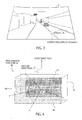
- Fig. 1 is a view showing a vehicle 5 on which a head-up display device 100 according to an embodiment of the present invention is mounted.
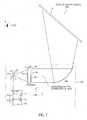
- Fig. 2 is a view showing a structure of the head-up display device 100 according to the embodiment of the present invention.
- the drawings explained below are schematic views, and may differ from an actual shape, size and arrangement.
- the head-up display device 100 is to be mounted on the vehicle 5, and is configured to project, from a projecting unit 85, speed information display, navigation information display, etc., as a virtual image, onto a windshield 6 or a combiner (not shown) disposed between a driver and the windshield 6, so as make a superposed display in which the virtual image is superposed on a foreground of a front viewing field.
- Fig. 3 is a view showing superposed image display of information performed by the head-up display device 100 according to the embodiment of the present invention.
- Fig. 3 shows an example of an image of the windshield 6 viewed by a observer's eye E of a driver of the vehicle 5.
- Fig. 2 mainly shows an example of a structure of the projection unit 85 of the head-up display device 100 according to the embodiment of the present invention.
- Coordinates in the projection unit 85 are defined by three-dimensional orthogonal coordinates of x, y and z.
- light emitted from a first light source 11 is light that is emitted in a direction parallel with the x direction.
- an optical axis of the transmission type screen 50 is in parallel with the z direction.
- the optical axis of the transmission type screen 50 is defined as a normal line of a first surface passing through a center of gravity of a microlens array 57.
- a direction of the axis in parallel with the x-axis is sometimes referred to as a first direction, and a direction of the axis in parallel with the y-axis is sometimes referred to as a second direction (perpendicular to the first direction).
- the projector 10 includes a first light source 11, a second light source 12, a third light source 13, a first dichroic prism 21, a second dichroic prism 22, a collimator lens 26 and so on.
- the first light source 11, the second light source 12 and the third light source 13 emit light of different wavelengths from one another.
- the first light source 11 emits light of a first wavelength
- the second light source 12 emits light of a second wavelength
- the third light source 13 emits light of a third wavelength.
- the light of the first wavelength emitted from the first light source 11 may be blue light
- the light of the second wavelength emitted from the second light source 12 may be green light
- the light of the third wavelength emitted from the third light source 13 may be red light.
- the second light source 12 and the third light source 13 various laser apparatuses such as semiconductor laser apparatuses (laser light sources) that emit laser light as coherent light.
- semiconductor laser apparatuses laser light sources
- the light of the first wavelength emitted from the first light source 11 and the light of the second wavelength emitted from the second light source 12 respectively enter into different surfaces of the first dichroic prism 21, and the light of the third wavelength emitted from the third light source 13 enters into the second dichroic prism 22.
- the light of the first wavelength emitted from the first light source 11 transmits through the first dichroic prism 21, while the light of the second wavelength emitted from the second light source 12 is reflected by the first dichroic prism 21.
- the light of the first wavelength and the light of the second wavelength are combined.
- the thus combined light of the light of the first wavelength and the light of the second wavelength enters into the second dichroic prism 22.
- the light of the first wavelength emitted from the first light source 11 and the light of the second wavelength emitted from the second light source 12 transmit through the second dichroic prism 22, while the light of the third wavelength emitted from the third light source 13 is reflected by the second dichroic prism 22.
- the light of the first wavelength, the light of the second wavelength and the light of the third wavelength are combined.
- the laser light which is the combination of the light of the first wavelength, the light of the second wavelength and the light of the third wavelength formed by the second dichroic prism 22, passes through the collimator lens 26 so as to be reflected by a projection mirror 30, and enters into the transmission type screen 50.
- the projection mirror 30 has a function of bidimensionally changing an angle. Thus, light incident thereon can be bidimensionally scanned, so that a projection image by desired laser light is formed.
- the projection mirror 30 is configured to be movable in a rotation direction (a) about a first axis (not shown) in parallel with the y-axis, and to be movable in a rotation direction (b) about a second axis (not shown) perpendicular to the first axis.
- the projection mirror 30 can be suitably replaced with another optical member, as long as it can bidimensionally scan light incident thereon.
- an optical member it is possible to suitably use a galvanometer mirror, a galvanometer scanner, a polygon mirror, a prism, an acousto-optical element, an optical element using MEMS (Micro Electro Mechanical System) technique, etc.
- MEMS Micro Electro Mechanical System
- a point of the projection mirror 30 into which laser light enters and by which the laser light is reflected, and a point at which the optical axis of the transmission type screen 50 and the projection mirror 30 intersect with each other correspond to each other.
- An optical path length between a laser light reflection point r 0 in the projection mirror 30 and an uppermost scanning point s 1 in the transmission type screen 50, and an optical path length between the laser light reflection point r 0 in the projection mirror 30 and a lowermost scanning point s 2 in the transmission type screen 50, are equivalent to each other.
- the transmission type screen 50 is an optical member formed of a transparent substrate having a predetermined transmission factor or more.
- the transmission type screen 50 can be formed by using and molding an organic resin material, or formed by using an inorganic material such as glass.
- Fig. 4 is a perspective view of the transmission type screen 50 according to the embodiment of the present invention.
- a direction of the axis in parallel with the x-axis is defined as a first direction
- a direction of the axis in parallel with the y-axis is defined as a second direction (perpendicular to the first direction).
- the transmission type screen 50 includes a first surface 51 extending in the first direction and the second direction perpendicular to the first direction, and a second surface 52 opposed to the first surface 51 and extending in the first direction and the second direction.
- the first surface 51 of the transmission type screen 50 is equipped with a microlens array 57 in which a plurality of microlenses 55 are cyclically arrayed.
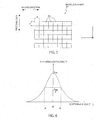
- Fig. 5 is a view showing the microlens array 57 extending in the first direction and the second direction, which is seen from a z-axis direction. As shown in the figure, when seen from the z-axis direction, a square microlens 55 whose side length is d is used in the transmission type screen 50 according to the embodiment. Pitches along which the microlenses 55 are arrayed are preferably the same in the first direction and the second direction. This is because the microlenses 55 are densely arrayed so as to reduce straight transmission light.
- Each microlens 55 is a spherical lens or a non-spherical lens.
- the microlens 55 has, at an apex on the side of the first surface 51, a curvature of a radius of curvature R 1 in the first direction and a curvature of a radius of curvature R 2 in the second direction.
- the apex means a point at which each microlens 55 projects most in the z-axis direction.
- a sectional shape in a plane of each microlens 55 which is in parallel with the first direction and includes the optical axis of the microlens 55, differs from a sectional shape in a plane of each microlens 55, which is in parallel with the second direction and includes the optical axis of the microlens 55.
- the radius of curvature R 1 in the first direction and the radius of curvature R 2 in the second direction at the apex on the side of the first surface 51 of the microlens 55 may be equivalent to each other, they are preferably different from each other.
- image information to be displayed by the head-up display device 100 has different aspect ratios.
- the radius of curvature R 1 in the first direction and the radius of curvature R 2 in the second direction at the apex on the side of the first surface 51 of the microlens 55 preferably differ from each other.
- the radius of curvature R 1 in the first direction at the apex on the side of the first surface 51 of the microlens 55 is preferably larger than the radius of curvature R 2 in the second direction.
- the second surface 52 of the transmission type screen 50 is equipped with a light diffusion surface 60 which functions as an isotropic light diffuser.
- the light diffusion surface 60 includes micro-irregularities of random cycle.
- a part (including the microlens array 57) of the transmission type screen 50, which is other than the light diffusion surface 60, is transparent and functions as anisotropic diffuser.
- the light diffusion surface 60 having micro-irregularities of random cycle will be apparent from the below description about manufacturing steps. Similarly to frosted glass, the light diffusion surface 60 is formed by providing micro-scratches in a smooth surface.
- a diffuser panel may be used as the transmission type screen of the head-up display device 100.
- speckle noise caused by laser light can be advantageously more prevented by using the microlens array 57, as compared with the use of the diffuser panel.
- the transmission type screen since an image is formed by the microlens array 57, light can be more efficiently transmitted in a viewing direction, as compared with a case in which an image is formed by using a screen, whereby increase in brightness can be achieved. In addition, sufficient brightness can be obtained even by a small quantity of light. Thus, an output of each laser light source can be decreased to save energy.
- An image formed by the laser light on the microlens array 57 of the transmission type screen 50 is reflected by a concave mirror 80 so as to be projected on the windshield 6.
- the projection unit 85 may be of either a structure in which an image is projected on the windshield 6 of the vehicle, or a structure in which an image is projected on a combiner (not shown) disposed between the driver and the windshield 6.
- this embodiment employs a layout in which the first surface 51 having the microlens array 57 of the transmission type screen 50 is disposed on the side of the light source of laser light
- a layout in which the second surface 52 of the transmission type screen 50 is disposed on the side of the light source may be employed.
- the former layout enables a clearer optical path, whereby a simulation precision upon design of the microlens array 57 can be improved.
- An optical member disposed between the transmission type screen 50 and the windshield 6 or the combiner (not shown) is not limited to the concave mirror 80. Another suitable optical member can be used depending on a layout of the transmission type screen 50 and the windshield 6 or the combiner (not shown).
- the transmission type screen 50 is applied to the head-up display device 100 that employs a laser projector system including the projector 10 and the projection mirror 30 as a drawing system of the head-up display device 100.
- the transmission type screen 50 can be applied to the head-up display device 100 that employs an LCOS system using an LED and an LCOS (Liquid crystal on silicon) element, or a DLP (Digital Light Processing) system using an LED and a DMD (Digital Mirror Device) element.
- the head-up display device 100 can be realized in such a manner that light from the LED as a light source is selectively reflected by the LCOS element, which is a reflective liquid crystal element, toward the transmission type screen 50.
- the head-up display device 100 can be realized in such a manner that light from the LED as a light source is selectively reflected by the DMD element, which is a reflective element having a plurality of micro-mirrors, toward the transmission type screen 50.
- a base material of the transmission type screen 50 is described. Any material can be used as the base material of the transmission type screen 50, as long as it is a transparent material.
- a thermoplastic resin, a thermosetting resin, a UV curing resin, an electron beam curing resin, glass or the like can be used.
- thermoplastic resin When a thermoplastic resin is used as the base material of the transmission type screen 50, a polycarbonate resin, an acryl-based resin, a fluorine-based acryl resin, a silicone-based acryl resin, an epoxy acrylate resin, a polystyrene resin, a cycloolefin polymer, a methyl styrene resin, a fluorene resin, PET, polypropylene and so on can be used.
- a polycarbonate resin an acryl-based resin, a fluorine-based acryl resin, a silicone-based acryl resin, an epoxy acrylate resin, a polystyrene resin, a cycloolefin polymer, a methyl styrene resin, a fluorene resin, PET, polypropylene and so on can be used.
- the transmission type screen 50 is formed of one base material. It is possible that a part that functions as an anisotropic diffuser including the microlens array 57 and a part including the light diffusion surface 60 functioning as an isotropic light diffuser are manufactured as separate members, and that these members are joined by means of an adhesive and so on. Note that, in this case, all the members have preferably the same refractive index. Further, the part functioning as an anisotropic diffuser and the part including the light diffusion surface 60 are preferably formed of the same material.
- the microlens array 57 can be formed in the following manner.
- a metal mold is mechanically cut into a microlens array mold by using a nano-machining apparatus, and the mold is transferred to a transparent resin.
- the processing method of the microlens array 57 the method of transferring the mold to a resin by injection molding can be also used.
- a method in which the microlens array 57 is directly formed by mechanically cutting a transparent resin can also be used.
- a resist / reflow method an ink-jet method, a electron beam exposure method, a laser beam drawing method, a method using chemical etching or plasma etching, a method using a punch and so on can be employed.
- a diffusion angle which is frequently used later, is defined.
- Fig. 6 is a view for describing a definition of the diffusion angle.
- a diffusion angle ⁇ is defined as follows. Light is perpendicularly made to enter into the transmission type screen 50, and a maximum scattered light intensity I max of the light emergent from the transmission type screen 50 is obtained.
- the diffusion angle ⁇ is a full width at half maximum (FWHM) that is a difference between two angles which are half the maximum scattered light intensity I max .
- a diffusion angle ⁇ H in the horizontal direction (second direction) and a diffusion angle ⁇ V in the vertical direction (first direction), which are shown in Fig. 4 has preferably a relationship ⁇ H > ⁇ V . This is because image information to be displayed by the head-up display device 100 is horizontally long.
- the horizontal diffusion angle ⁇ H is not less than 20° and not more than 60°, and the vertical diffusion angle ⁇ V is not less than 5° and not more than 35° More preferably, the horizontal diffusion angle ⁇ H is not less than 20° and not more than 50°, and the vertical diffusion angle ⁇ V is not less than 10° and not more than 30°. In this case, the transmission type screen 50 used in the head-up display device 100 is optimum.
- Fig. 7 is a view for describing definitions ⁇ L and S 80-20 .
- ⁇ L is a ratio of a difference between a maximum value and a minimum value relative to the maximum value, of standardized scattered light intensity of light emergent from the transmission type screen 50. When there is no minimum value, ⁇ L is regarded as 0. When such ⁇ L is not more than 7%, more preferably, not more than 5%, the transmission type screen 50 used in the head-up display 100 is optimum.
- S 80-20 is defined as an angular difference between 80% of a scattered light intensity of light emergent from the transmission type screen 50 and 20% thereof.
- S 80-20 is not more than 10%, more preferably, not more than 7%, the transmission type screen 50 used in the head-up display 100 is optimum.
- the scattered light intensity is based on a Y value of the XYZ color system (CIE1931 color system).
- FIGS. 8 to 11 are views for schematically describing manufacturing steps of the transmission type screen 50 according to the embodiment of the present invention.
- Fig. 8(A) shows a first metal mold material 110.
- One surface of such a first metal mold material 110 is mechanically cut by a nano-machining apparatus (not shown) so as to obtain a first mold 115 in which a pattern corresponding to the microlens array 57 is formed, as shown in Fig. 8(B) .
- this embodiment uses a method of transferring the microlens array 57 to a resin by injection molding by means of such a first mold 115, a method in which the microlens array 57 is directly machined in a transparent resin by mechanical cutting can be also used.
- the first mold 115 is created by mechanical cutting by means of a nano-machining apparatus, and the microlens array 57 is transferred to a resin by injection molding is most preferred.
- the transmission type screen 50 is required to be subjected to a non-spherical processing of nano unit.
- the nano-machining apparatus can be suitably used in this processing.
- Fig. 9(A) shows a second metal mold material 120.
- One surface of such a second metal mold material 120 is sandblasted, so as to obtain an intermediate member 123 shown in Fig. 9(B) .
- the sandblasted surface of the intermediate member 123 is further bead-blasted, so as to obtain a second mold 125 shown in Fig. 9(C) .
- This embodiment employs a method in which micro-irregularities are transferred to a resin by injection molding by means of such a second metal mold material 120. Since micro-irregularities are transferred to the blasted surface, a cycle of the irregularities is random. The thus manufactured micro-irregularities function as the light diffusion surface 60, so that light is isotropically diffused.
- random means that the array of micro-irregularities does not have regularity.
- the second metal mold material 120 is sandblasted and is further bead-blasted so as to form a transfer pattern of the micro-irregularities.
- the transfer pattern of the micro-irregularities may be formed only by either sandblasting or bead-blasting the second metal mold material 120.
- the diffusion property can be controlled by the sandblasting and the surface can be smoothened by the bead-blasting.
- haze of the light diffusion surface 60 created by the second mold 125 can be reduced.
- Fig. 10 shows that a space between the first mold 115 and the second mold 125 is filled with a transparent resin material 130.
- Fig. 11 shows that, after the resin material 130 is cured (solidified), the resin material 130 is demolded from the first mold 115 and the second mold 125, so as to obtain the transmission type screen 50 according to the present invention.
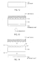
- Figs. 12 to 16 are views schematically showing manufacturing steps of the transmission type screen 50 according to another embodiment of the present invention.
- a transparent substrate 150 having two main surfaces shown in Fig. 12 is prepared.
- a polycarbonate rein can be used as a material of such a substrate 150.
- a first mold 115 to which an ultraviolet curing resin material 154 is applied is arranged on one surface of the substrate 150, and a reference sheet 156 is arranged on the other surface of the substrate 150.
- the substrate 150 is irradiated with ultraviolet light from the side of the reference sheet 156 so as to cure the ultraviolet curing rein material 154.
- the first mold 115 is remolded, and the reference sheet 156 is peeled, so that it is possible to obtain the substrate 150 which is equipped, on the one surface thereof, with a microlens array part 157 obtained by curing the ultraviolet curing resin material 154.
- the other surface of the substrate 150 which is not equipped with the microlens array part 157, is sandblasted.
- the other surface which is sandblasted by the step shown in Fig. 15 , is bead-blasted as shown in Fig. 16 , so as to obtain micro-irregularities.
- the transmission type screen 50 having the light diffusion surface 60 can be obtained.
- the other surface of the substrate is sandblasted and is further bead-blasted so as to form the micro-irregularities.
- the micro-irregularities may be formed on the other surface of the substrate 150 only by either sandblasting or bead-blasting the other surface of the substrate 150.
- the diffusion property can be controlled by the sandblasting and the surface can be smoothened by the bead-blasting.
- haze of the light diffusion surface 60 created by the the other surface of the substrate 150 can be reduced.
- the above-described micro-irregularities can be obtained as an arithmetic average surface roughness Sa.
- the arithmetic average surface roughness Sa can be obtained based on International Standard ISO 25178: Geometric Product Specifications (GPS) - Surface texture: areal.
- GPS Geometric Product Specifications
- the arithmetic average surface roughness Sa can be obtained by measuring the micro-irregularities by means of a laser microscope OLS4100 (Olympus) or VK-X (Keyence).
- Saof the micro-irregularities of the light diffusion surface can be measured by a laser microscope OLS4100 (Olympus) or VK-X (Keyence) (because the structure of the micro-irregularities is not a structure not more than wavelength).
- telescopic molds capable of injection molding an outline of 60 mm ⁇ 90 mm ⁇ 2 mmt were created using NAK80 manufactured by Daido Steel Co., Ltd.
- the first metal molding material 110 was mechanically cut (ROBONANO manufactured by FANUC) to form the following two kinds of first molds 115 on which a non-spherical microlens array was inverted.
- the second metal mold material 120 was machined according to the following procedure, so as to create 13 kinds of second molds 125 on which a random micro-irregularity pattern was formed. (Note that there is included one second mold 125 in which (Procedure 2) was omitted.)
- the first mold 115 and the second cold 125 were assembled and injection-molded, so that the transmission type screen 50 in which the microlens array 57 and the light diffusion surface 60 formed of the micro-irregularities were combined was obtained.
- a material and injection molding conditions were as follows.
- Tables 1 to 4 show the result.
- Table 2 shows the processing condition of the second mold 125, an arithmetic average surface roughness Sa of the light diffusion surface 60 created by the second mold 125, and a haze value of the light diffusion surface 60.
- a measuring method of a haze value is based on JIS K 7136.
- a column "diffusion angle ratio" of Tables 3 and 4 shows a calculated value of diffusion angle of D X / diffusion angle of MLA Y .
- Tables 3 and 4 show an arithmetic average surface roughness Sa of the light diffusion surface 60, and a haze value of the light diffusion surface 60.
- a sample having a suitable diffusion angle ratio is employed as the transmission type screen 50 according to the present invention.
- a suitable transmission type screen 50 according to the present invention has the diffusion angle of the light diffusion surface 60 which is not less than 0.2 times and not more than 0.4 times the diffusion angle of the microlens array 57.
- a rate of the diffusion angle of the light diffusion surface 60 relative to the diffusion angle of the microlens array 57 (light diffusion angle ratio) being not less than 0.2 and not more than 0.4 is suitable.
- a sample in which the light diffusion surface 60 has a suitable arithmetic surface roughness Sa is employed as the transmission type screen 50 according to the present invention.
- a transmission type screen in which an arithmetic surface roughness Sa of the light diffusion surface 60 is not less than 0.13 ⁇ m and not more than 1.30 ⁇ m is suited as the transmission type screen 50 according to the present invention.
- a sample in which the light diffusion surface 60 has a suitable haze value is employed as the transmission type screen 50 according to the present invention.
- a transmission type screen in which a haze value of the light diffusion surface 60 is not less than 35% and not more than 70% is suited as the transmission type screen 50 according to the present invention.
- a haze value When a haze value is too large, a transmission factor lowers, which results in a dark image. On the other hand, when a haze value is too small, a suitable diffusion cannot be obtained. Thus, it can be estimated that to constitute the transmission type screen 50 in such a manner that a haze value of the light diffusion surface 60 is in a range between 35% and 70% is preferred.
- Fig. 17 is a view for describing an effect of the transmission type screen 50 according to the embodiment of the present invention.
- (A) is a characteristic diagram showing a scattering angle dependence of a scattered light intensity of an isotropic diffuser only
- (B) is a characteristic diagram showing a scattering angle dependence of a scattered light intensity of the microlens array 57 only
- (C) is a characteristic diagram showing a scattering angle dependence of a scattered light intensity of the transmission type screen 50 according to the present invention in which the isotropic diffuser and the microlens array 57 are combined.
- a light intensity thereof is a Gaussian distribution in which the center (0°) has intensive brightness.
- a light intensity variation within a view angle is large.
- the scattered light intensity has two peaks P 1 and P 2 , which is described above in the "DISCLOSURE OF THE INVENTION" column.
- (A) and (B) are combined, i.e., the isotropic diffuser and the microlens array 57 are combined, whereby the characteristics of (A) and (B) are combined.
- a rate of the diffusion angle of the light diffusion surface 60 as the isotropic diffuser relative to the diffusion angle of the microlens array 57 is not less than 0.2 and not more than 0.4.
- the second surface 52 is equipped with the light diffusion surface 60, and a rate of the diffusion angle of the light diffusion surface 60 relative to the diffusion angle of the microlens array 57 is not less than 0.2 and not more than 0.4.
- a scattered light intensity is flat within a predetermined scattering angle.
- the head-up display device 100 according to the present invention uses the aforementioned transmission type screen 50, the head-up display device 100 according to the present invention has a uniform light intensity within a view angle.
- the second embodiment differs from the above first embodiment only in the structure of the microlens array 57 provided on the first surface 51 of the transmission type screen 50. Thus, this point is described.
- Fig. 18 is a view showing a microlens array 57 extending in a first direction and a second direction, which is seen from a z-axis direction, of the transmission type screen 50 according to another embodiment of the present invention.
- the microlens 55 of the microlens array 57 provided on the first surface 51 of the transmission type screen 50 according to the first embodiment is square, when seen from the z-axis direction.
- the microlens 55 of the microlens array 57 provided on the first surface 51 of the transmission type screen 50 according to the second embodiment is structured as a rectangle, when seen from the z-axis direction.
- d 1 ⁇ d 2 is preferable. This is because image information to be displayed by the head-up display device 100 is generally horizontally long.
- the radius of curvature R 1 in the first direction at the apex on the side of the first surface 51 of each microlens 55 is preferably larger than the radius of curvature R 2 in the second direction.
- the third embodiment differs from the above first embodiment only in the structure of the microlens array 57 provided on the first surface 51 of the transmission type screen 50. Thus, this point is described.
- Fig. 19 is a view showing a microlens array 57 extending in a first direction and a second direction, which is seen from a z-axis direction, of the transmission type screen 50 according to another embodiment of the present invention.
- the microlens 55 of the microlens array 57 provided on the first surface 51 of the transmission type screen 50 according to the first embodiment is square, when seen from the z-axis direction.
- the microlens 55 of the microlens array 57 provided on the first surface 51 of the transmission type screen 50 according to the third embodiment is structured as a regular hexagon, when seen from the z-axis direction.
- the radius of curvature R 1 in the first direction at the apex on the side of the first surface 51 of each microlens 55 is preferably larger than the radius of curvature R 2 in the second direction.
- the fourth embodiment differs from the above first embodiment only in the structure of the microlens array 57 provided on the first surface 51 of the transmission type screen 50. Thus, this point is described.
- Fig. 20 is a view showing a microlens array 57 extending in a first direction and a second direction, which is seen from a z-axis direction, of the transmission type screen 50 according to another embodiment of the present invention.
- the microlens 55 of the microlens array 57 provided on the first surface 51 of the transmission type screen 50 according to the first embodiment is square, when seen from the z-axis direction.
- the microlens 55 of the microlens array 57 provided on the first surface 51 of the transmission type screen 50 according to the fourth embodiment is structured as a hexagon that is not a regular hexagon, when seen from the z-axis direction.
- a horizontally long hexagon is preferable in which only a side in parallel with the second direction is longer than lengths of other sides. This is because image information to be displayed by the head-up display device 100 is generally horizontally long.
- the radius of curvature R 1 in the first direction at the apex on the side of the first surface 51 of each microlens 55 is preferably larger than the radius of curvature R 2 in the second direction.
- the fifth embodiment differs from the above first embodiment only in the structure of the microlens array 57 provided on the first surface 51 of the transmission type screen 50. Thus, this point is described.
- Fig. 21 is a view showing a microlens array 57 extending in a first direction and a second direction, which is seen from a z-axis direction, of the transmission type screen 50 according to another embodiment of the present invention.
- the microlens 55 of the microlens array 57 provided on the first surface 51 of the transmission type screen 50 according to the first embodiment is square, when seen from the z-axis direction.
- the microlens 55 of the microlens array 57 provided on the first surface 51 of the transmission type screen 50 according to the fifth embodiment is structured as an ellipse, when seen from the z-axis direction.
- a horizontally long ellipse is preferable in which a major axis ⁇ 1 in parallel with the second direction and a minor axis ⁇ 2 is in parallel with the first direction. This is because image information to be displayed by the head-up display device 100 is generally horizontally long.
- the radius of curvature R 1 in the first direction at the apex on the side of the first surface 51 of each microlens 55 is preferably larger than the radius of curvature R 2 in the second direction.
- the sixth embodiment differs from the above first embodiment only in the structure of the microlens array 57 provided on the first surface 51 of the transmission type screen 50. Thus, this point is described.
- Fig. 22 is a view showing a microlens array 57 extending in a first direction and a second direction, which is seen from a z-axis direction, of the transmission type screen 50 according to another embodiment of the present invention.
- the microlens 55 of the microlens array 57 provided on the first surface 51 of the transmission type screen 50 according to the first embodiment is square, when seen from the z-axis direction.
- the microlens 55 of the microlens array 57 provided on the first surface 51 of the transmission type screen 50 according to the sixth embodiment is structured as a koban (Japanese old coin) shape, when seen from the z-axis direction.
- a horizontally long koban is preferable in which a linear part of the koban shape is in parallel with the second direction. This is because image information to be displayed by the head-up display device 100 is generally horizontally long.
- the radius of curvature R 1 in the first direction at the apex on the side of the first surface 51 of each microlens 55 is preferably larger than the radius of curvature R 2 in the second direction.
- the present invention is not limited only to the first to sixth embodiments, and an embodiment in which structures of the respective embodiments are suitably combined is included in the scope of the present invention.
- a transmission type screen of a head-up display device is required to have a scattered light intensity that is flat as much as possible within a predetermined scattering angle.
- a conventional transmission type screen formed by a microlens array does not have a flat scattered light intensity, which causes a problem.
- the second surface is equipped with the light diffusion surface, and a rate of the diffusion angle of the light diffusion surface relative to the diffusion angle of the microlens array is not less than 0.2 and not more than 0.4.
- the transmission type screen according to the present invention has a flat scattered light intensity within a predetermined scattering angle.
- the transmission type screen according to the present invention has a great industrial applicability.
Landscapes
- Physics & Mathematics (AREA)
- General Physics & Mathematics (AREA)
- Engineering & Computer Science (AREA)
- Optics & Photonics (AREA)
- Combustion & Propulsion (AREA)
- Mechanical Engineering (AREA)
- Transportation (AREA)
- Chemical & Material Sciences (AREA)
- Theoretical Computer Science (AREA)
- Signal Processing (AREA)
- Multimedia (AREA)
- Overhead Projectors And Projection Screens (AREA)
- Optical Elements Other Than Lenses (AREA)
- Instrument Panels (AREA)
Claims (10)
- Bildschirm (50) vom Transmissions- bzw. Übertragungstyp, umfassend eine erste Fläche bzw. Oberfläche (51) und eine zweite Fläche bzw. Oberfläche (52) gegenüberliegend bzw. entgegengesetzt zu der ersten Oberfläche (51), wobei:die erste Oberfläche (51) mit einer Mikrolinsenanordnung (57) ausgestattet ist, die eine Mehrzahl von Mikrolinsen (55) enthält;die zweite Oberfläche (52) mit einer Lichtdiffusionsfläche bzw. -oberfläche (60) ausgestattet ist;dadurch gekennzeichnet, dassdie Mikrolinsenanordnung (57) und die Lichtdiffusionsoberfläche (60) jeweils einen Diffusionswinkel aufweisen, der als eine Halbwertsbreite bzw. volle Breite bei halbem Maximum definiert ist, was eine Differenz zwischen zwei Winkeln bei der Hälfte der maximalen Streulichtintensität eines Lichts ist, das senkrecht in den Bildschirm (50) vom Übertragungstyp eintritt und aus diesem austritt; undein Diffusionswinkelverhältnis des Diffusionswinkels der Lichtdiffusionsoberfläche (60) relativ zu dem Diffusionswinkel der Mikrolinsenanordnung (57) nicht weniger als 0,2 und nicht mehr als 0,4 beträgt.
- Bildschirm (50) vom Transmissionstyp nach Anspruch 1, wobei die Lichtdiffusionsoberfläche (60) Mikrounregelmäßigkeiten aufweist.
- Bildschirm (50) vom Transmissionstyp nach Anspruch 2, wobei ein Zyklus der Mikrounregelmäßigkeiten zufällig ist.
- Bildschirm (50) vom Transmissionstyp nach einem der Ansprüche 1 bis 3, wobei eine arithmetische durchschnittliche Flächen- bzw. Oberflächenrauigkeit der Lichtdiffusionsoberfläche (60) nicht weniger als 0,13 µm und nicht mehr als 1,30 µm beträgt.
- Bildschirm (50) vom Transmissionstyp nach einem der Ansprüche 1 bis 3, wobei ein Trübungswert der Lichtdiffusionsoberfläche (60) nicht weniger als 35% und nicht mehr als 70% beträgt.
- Bildschirm (50) vom Transmissionstyp nach einem der Ansprüche 1 bis 5, wobei
die Mehrzahl von Mikrolinsen (55) in einer ersten Richtung und einer zweiten Richtung angeordnet sind, welche die erste Richtung kreuzt, und
sich ein Krümmungsradius jeder Mikrolinse (55) in der ersten Richtung und ein Krümmungsradius davon in der zweiten Richtung voneinander unterscheiden. - Head-up-Anzeigevorrichtung (100), wobei der Bildschirm (50) vom Transmissionstyp nach einem der Ansprüche 1 bis 6 verwendet wird.
- Head-up-Anzeigevorrichtung (100) nach Anspruch 7, umfassend:eine Laserlichtquelle, die konfiguriert ist, Laserlicht zu emittieren; undeinen Scanner, der konfiguriert ist dem Laserlicht zu erlauben, auf dem Bildschirm (50) vom Transmissionstyp zu scannen.
- Head-up-Anzeigevorrichtung (100) nach Anspruch 7, umfassend:eine LED, die konfiguriert ist, Licht zu emittieren; undein LCOS-Element, das konfiguriert ist, das Licht auf den Bildschirm (50) vom Transmissionstyp zu reflektieren.
- Head-up-Anzeigevorrichtung (100) nach Anspruch 7, umfassend:eine LED, die konfiguriert ist, Licht zu emittieren; undein DMD-Element, das konfiguriert ist, das Licht auf den Bildschirm (50) vom Transmissionstyp zu reflektieren.
Applications Claiming Priority (2)
| Application Number | Priority Date | Filing Date | Title |
|---|---|---|---|
| JP2015019904 | 2015-02-04 | ||
| PCT/JP2016/053200 WO2016125824A1 (ja) | 2015-02-04 | 2016-02-03 | 透過型スクリーン及びそれを用いたヘッドアップディスプレイ装置 |
Publications (3)
| Publication Number | Publication Date |
|---|---|
| EP3255492A1 EP3255492A1 (de) | 2017-12-13 |
| EP3255492A4 EP3255492A4 (de) | 2018-10-24 |
| EP3255492B1 true EP3255492B1 (de) | 2021-01-06 |
Family
ID=56564164
Family Applications (1)
| Application Number | Title | Priority Date | Filing Date |
|---|---|---|---|
| EP16746655.6A Active EP3255492B1 (de) | 2015-02-04 | 2016-02-03 | Lichtdurchlässiger schirm und frontsichtanzeigevorrichtung damit |
Country Status (5)
| Country | Link |
|---|---|
| US (1) | US10509225B2 (de) |
| EP (1) | EP3255492B1 (de) |
| JP (1) | JP6601742B2 (de) |
| CN (1) | CN107209449B (de) |
| WO (1) | WO2016125824A1 (de) |
Families Citing this family (13)
| Publication number | Priority date | Publication date | Assignee | Title |
|---|---|---|---|---|
| JP6717264B2 (ja) * | 2017-06-08 | 2020-07-01 | 株式会社Jvcケンウッド | 虚像表示装置、中間像形成部および画像表示光生成ユニット |
| KR102311183B1 (ko) * | 2017-06-22 | 2021-10-12 | 현대모비스 주식회사 | 차량용 헤드업 디스플레이 장치 |
| CN108490616B (zh) * | 2018-04-03 | 2020-04-10 | 京东方科技集团股份有限公司 | 抬头显示器及显示控制方法 |
| CN208172483U (zh) * | 2018-05-16 | 2018-11-30 | 中强光电股份有限公司 | 投影机、照明系统及扩散元件 |
| JP2020021038A (ja) * | 2018-08-03 | 2020-02-06 | 住友ベークライト株式会社 | 異方性拡散板、バックライトユニット、液晶表示装置および電子機器 |
| JP2020021037A (ja) * | 2018-08-03 | 2020-02-06 | 住友ベークライト株式会社 | 異方性拡散板、バックライトユニット、液晶表示装置および電子機器 |
| CN112083597B (zh) * | 2019-06-12 | 2023-09-01 | 群创光电股份有限公司 | 显示器及其显示面板与制作方法 |
| KR102214328B1 (ko) * | 2019-07-01 | 2021-02-15 | 주식회사 멤스룩스 | 비대칭형 출광 패턴을 갖는 디퓨져 및 이의 제조 방법 |
| CN110941136A (zh) * | 2020-01-03 | 2020-03-31 | 深圳市锐思华创技术有限公司 | 一种应用定向扩散片的激光投影系统 |
| WO2021139992A1 (en) | 2020-01-06 | 2021-07-15 | Saint-Gobain Glass France | Glass vehicle roof with projection transparent screen |
| CN111239869B (zh) * | 2020-03-19 | 2022-02-22 | 宁波舜宇车载光学技术有限公司 | 扩散板 |
| CN120418679A (zh) * | 2022-12-27 | 2025-08-01 | Scivax株式会社 | 光学系统装置 |
| JPWO2024143433A1 (de) * | 2022-12-27 | 2024-07-04 |
Family Cites Families (28)
| Publication number | Priority date | Publication date | Assignee | Title |
|---|---|---|---|---|
| JPS5960431A (ja) * | 1982-09-30 | 1984-04-06 | Mitsubishi Rayon Co Ltd | 背面投影スクリ−ン |
| JPH02213825A (ja) * | 1989-02-15 | 1990-08-24 | Asahi Chem Ind Co Ltd | 高解像度透過型スクリーン |
| US5760955A (en) * | 1995-04-06 | 1998-06-02 | Philips Electronics North America Corporation | Rear projection screen with reduced speckle |
| JP2001201611A (ja) * | 2000-01-21 | 2001-07-27 | Hitachi Ltd | 光学的機能性シート及びこれを用いた面状光源並びに画像表示装置 |
| DE10105958A1 (de) | 2001-02-09 | 2002-09-12 | Fraunhofer Ges Forschung | Vorrichtung zur anisotropen Lichtstreuung sowie Verfahren zur Herstellung der Vorrichtung |
| JP2006285156A (ja) * | 2005-03-08 | 2006-10-19 | Kuraray Co Ltd | 背面投写型スクリーン及び背面投写型表示装置 |
| JP2006330631A (ja) | 2005-05-30 | 2006-12-07 | Miraial Kk | 背面投射型スクリーン |
| JP2006337459A (ja) * | 2005-05-31 | 2006-12-14 | Toppan Printing Co Ltd | レンズアレイシート及び背面投影型映写スクリーン |
| JP2007187760A (ja) * | 2006-01-11 | 2007-07-26 | Seiko Epson Corp | レンズ基板の製造方法、レンズ基板、透過型スクリーンおよびリア型プロジェクタ |
| US7660037B2 (en) * | 2006-06-06 | 2010-02-09 | Seiko Epson Corporation | Screen, projector, and image display device |
| CN100590466C (zh) * | 2006-10-18 | 2010-02-17 | 财团法人工业技术研究院 | 导光板及具有该导光板的背光模块 |
| US7969644B2 (en) | 2008-09-02 | 2011-06-28 | Elbit Systems Of America, Llc | System and method for despeckling an image illuminated by a coherent light source |
| JP2010145745A (ja) | 2008-12-18 | 2010-07-01 | Equos Research Co Ltd | 画像形成装置、及び、ヘッドアップディスプレイ装置 |
| KR101379924B1 (ko) * | 2010-07-02 | 2014-04-04 | 엘지이노텍 주식회사 | 백라이트유닛 및 이를 이용한 액정표시장치 |
| KR20120013708A (ko) * | 2010-08-06 | 2012-02-15 | 엘지이노텍 주식회사 | 광학시트, 이를 포함하는 백라이트 유닛 및 표시장치 |
| JP2012042518A (ja) * | 2010-08-12 | 2012-03-01 | Tohoku Univ | 反射型フロントスクリーンとそれを用いた立体表示システム |
| CN105425516B (zh) * | 2010-09-07 | 2017-07-18 | 大日本印刷株式会社 | 投射型影像显示装置及其空间光调制器的照明方法 |
| US9140831B2 (en) * | 2010-09-16 | 2015-09-22 | Dai Nippon Printing Co., Ltd. | Optical sheet, optical member, surface light source device, and liquid crystal display device |
| JP5310810B2 (ja) | 2011-08-27 | 2013-10-09 | 株式会社デンソー | ヘッドアップディスプレイ装置 |
| JP5344069B2 (ja) * | 2011-08-29 | 2013-11-20 | 株式会社デンソー | ヘッドアップディスプレイ装置 |
| JP5896366B2 (ja) * | 2012-01-13 | 2016-03-30 | エルジー・ケム・リミテッド | マイクロレンズアレイシート及びこれを含むバックライトユニット |
| KR101413140B1 (ko) * | 2012-04-18 | 2014-07-01 | 주식회사 케이씨씨 | 불균일한 로컬 마이크로렌즈 어레이 패턴을 갖는 광확산판 및 이를 포함하는 액정표시장치 |
| US10502870B2 (en) * | 2012-10-04 | 2019-12-10 | North Inc. | Optical assembly |
| US20140268879A1 (en) * | 2013-03-14 | 2014-09-18 | Panasonic Corporation | Transparent waveguide diffuser for lighting and methods of manufacturing transparent waveguide diffuser |
| US10598925B2 (en) * | 2013-05-10 | 2020-03-24 | North Inc. | Projection device |
| JP6315240B2 (ja) | 2014-02-03 | 2018-04-25 | 株式会社リコー | 画像表示装置、移動体及びレンズアレイ |
| JP6489300B2 (ja) * | 2014-10-02 | 2019-03-27 | 大日本印刷株式会社 | 透過型スクリーン及びそれを用いたヘッドアップディスプレイ装置 |
| US9880441B1 (en) * | 2016-09-08 | 2018-01-30 | Osterhout Group, Inc. | Electrochromic systems for head-worn computer systems |
-
2016
- 2016-02-03 US US15/548,244 patent/US10509225B2/en active Active
- 2016-02-03 EP EP16746655.6A patent/EP3255492B1/de active Active
- 2016-02-03 WO PCT/JP2016/053200 patent/WO2016125824A1/ja not_active Ceased
- 2016-02-03 JP JP2016573398A patent/JP6601742B2/ja active Active
- 2016-02-03 CN CN201680008404.2A patent/CN107209449B/zh not_active Expired - Fee Related
Non-Patent Citations (1)
| Title |
|---|
| None * |
Also Published As
| Publication number | Publication date |
|---|---|
| CN107209449A (zh) | 2017-09-26 |
| EP3255492A4 (de) | 2018-10-24 |
| JP6601742B2 (ja) | 2019-11-06 |
| CN107209449B (zh) | 2020-03-06 |
| JPWO2016125824A1 (ja) | 2017-12-14 |
| WO2016125824A1 (ja) | 2016-08-11 |
| US20180348512A1 (en) | 2018-12-06 |
| US10509225B2 (en) | 2019-12-17 |
| EP3255492A1 (de) | 2017-12-13 |
Similar Documents
| Publication | Publication Date | Title |
|---|---|---|
| EP3255492B1 (de) | Lichtdurchlässiger schirm und frontsichtanzeigevorrichtung damit | |
| EP3264173A1 (de) | Lichtdurchlässiger schirm und blickfeldanzeigevorrichtung damit | |
| US7821717B2 (en) | Lenticular lens array element | |
| US10534112B2 (en) | Microlens array, image display apparatus, object apparatus, and mold | |
| JP2021182151A (ja) | 空中で結像するためのシステム | |
| EP3282293A1 (de) | Kompositdiffusionsplatte | |
| US11175440B2 (en) | Diffuser plate and projection-type image displaying device | |
| TWI604222B (zh) | 光學元件及投影裝置 | |
| JP2011034801A (ja) | 導光板、導光板の製造方法、面光源装置および液晶表示装置 | |
| CN101762959B (zh) | 激光投影装置以及制造激光投影装置的方法 | |
| JP6489300B2 (ja) | 透過型スクリーン及びそれを用いたヘッドアップディスプレイ装置 | |
| WO2013035791A1 (ja) | 導光板、面光源装置及び透過型画像表示装置 | |
| US12384247B2 (en) | Display device and head-up display | |
| JP2005215417A (ja) | マイクロレンズアレイ | |
| WO2012099123A1 (ja) | 導光板、面光源装置及び透過型画像表示装置 | |
| JP2016212294A (ja) | ディスプレイ装置 | |
| TWM505616U (zh) | 3d顯示層及3d顯示結構 | |
| JP2015064497A (ja) | リニアフレネルレンズシート及び透過型表示装置 | |
| JP2016212296A (ja) | 車両用情報表示装置 | |
| JP2016212295A (ja) | ディスプレイ装置 | |
| TW201624056A (zh) | 3d顯示層、3d顯示結構及其製作方法 |
Legal Events
| Date | Code | Title | Description |
|---|---|---|---|
| STAA | Information on the status of an ep patent application or granted ep patent |
Free format text: STATUS: THE INTERNATIONAL PUBLICATION HAS BEEN MADE |
|
| PUAI | Public reference made under article 153(3) epc to a published international application that has entered the european phase |
Free format text: ORIGINAL CODE: 0009012 |
|
| STAA | Information on the status of an ep patent application or granted ep patent |
Free format text: STATUS: REQUEST FOR EXAMINATION WAS MADE |
|
| 17P | Request for examination filed |
Effective date: 20170803 |
|
| AK | Designated contracting states |
Kind code of ref document: A1 Designated state(s): AL AT BE BG CH CY CZ DE DK EE ES FI FR GB GR HR HU IE IS IT LI LT LU LV MC MK MT NL NO PL PT RO RS SE SI SK SM TR |
|
| AX | Request for extension of the european patent |
Extension state: BA ME |
|
| RAP1 | Party data changed (applicant data changed or rights of an application transferred) |
Owner name: DAI NIPPON PRINTING CO., LTD. |
|
| DAV | Request for validation of the european patent (deleted) | ||
| DAX | Request for extension of the european patent (deleted) | ||
| A4 | Supplementary search report drawn up and despatched |
Effective date: 20180924 |
|
| RIC1 | Information provided on ipc code assigned before grant |
Ipc: G02B 3/00 20060101ALI20180918BHEP Ipc: H04N 5/74 20060101ALI20180918BHEP Ipc: G02B 27/01 20060101ALI20180918BHEP Ipc: B60K 35/00 20060101ALI20180918BHEP Ipc: G03B 21/00 20060101ALI20180918BHEP Ipc: G02B 26/10 20060101ALI20180918BHEP Ipc: G02B 5/02 20060101ALI20180918BHEP Ipc: G09F 9/00 20060101ALI20180918BHEP Ipc: G03B 21/62 20140101AFI20180918BHEP Ipc: G02B 26/08 20060101ALI20180918BHEP |
|
| GRAP | Despatch of communication of intention to grant a patent |
Free format text: ORIGINAL CODE: EPIDOSNIGR1 |
|
| STAA | Information on the status of an ep patent application or granted ep patent |
Free format text: STATUS: GRANT OF PATENT IS INTENDED |
|
| INTG | Intention to grant announced |
Effective date: 20200805 |
|
| GRAS | Grant fee paid |
Free format text: ORIGINAL CODE: EPIDOSNIGR3 |
|
| GRAA | (expected) grant |
Free format text: ORIGINAL CODE: 0009210 |
|
| STAA | Information on the status of an ep patent application or granted ep patent |
Free format text: STATUS: THE PATENT HAS BEEN GRANTED |
|
| AK | Designated contracting states |
Kind code of ref document: B1 Designated state(s): AL AT BE BG CH CY CZ DE DK EE ES FI FR GB GR HR HU IE IS IT LI LT LU LV MC MK MT NL NO PL PT RO RS SE SI SK SM TR |
|
| REG | Reference to a national code |
Ref country code: GB Ref legal event code: FG4D |
|
| REG | Reference to a national code |
Ref country code: AT Ref legal event code: REF Ref document number: 1353019 Country of ref document: AT Kind code of ref document: T Effective date: 20210115 Ref country code: CH Ref legal event code: EP |
|
| REG | Reference to a national code |
Ref country code: DE Ref legal event code: R096 Ref document number: 602016051006 Country of ref document: DE |
|
| REG | Reference to a national code |
Ref country code: IE Ref legal event code: FG4D |
|
| REG | Reference to a national code |
Ref country code: NL Ref legal event code: MP Effective date: 20210106 |
|
| REG | Reference to a national code |
Ref country code: AT Ref legal event code: MK05 Ref document number: 1353019 Country of ref document: AT Kind code of ref document: T Effective date: 20210106 |
|
| REG | Reference to a national code |
Ref country code: LT Ref legal event code: MG9D |
|
| PG25 | Lapsed in a contracting state [announced via postgrant information from national office to epo] |
Ref country code: HR Free format text: LAPSE BECAUSE OF FAILURE TO SUBMIT A TRANSLATION OF THE DESCRIPTION OR TO PAY THE FEE WITHIN THE PRESCRIBED TIME-LIMIT Effective date: 20210106 Ref country code: GR Free format text: LAPSE BECAUSE OF FAILURE TO SUBMIT A TRANSLATION OF THE DESCRIPTION OR TO PAY THE FEE WITHIN THE PRESCRIBED TIME-LIMIT Effective date: 20210407 Ref country code: FI Free format text: LAPSE BECAUSE OF FAILURE TO SUBMIT A TRANSLATION OF THE DESCRIPTION OR TO PAY THE FEE WITHIN THE PRESCRIBED TIME-LIMIT Effective date: 20210106 Ref country code: NO Free format text: LAPSE BECAUSE OF FAILURE TO SUBMIT A TRANSLATION OF THE DESCRIPTION OR TO PAY THE FEE WITHIN THE PRESCRIBED TIME-LIMIT Effective date: 20210406 Ref country code: PT Free format text: LAPSE BECAUSE OF FAILURE TO SUBMIT A TRANSLATION OF THE DESCRIPTION OR TO PAY THE FEE WITHIN THE PRESCRIBED TIME-LIMIT Effective date: 20210506 Ref country code: BG Free format text: LAPSE BECAUSE OF FAILURE TO SUBMIT A TRANSLATION OF THE DESCRIPTION OR TO PAY THE FEE WITHIN THE PRESCRIBED TIME-LIMIT Effective date: 20210406 Ref country code: LT Free format text: LAPSE BECAUSE OF FAILURE TO SUBMIT A TRANSLATION OF THE DESCRIPTION OR TO PAY THE FEE WITHIN THE PRESCRIBED TIME-LIMIT Effective date: 20210106 |
|
| PG25 | Lapsed in a contracting state [announced via postgrant information from national office to epo] |
Ref country code: AT Free format text: LAPSE BECAUSE OF FAILURE TO SUBMIT A TRANSLATION OF THE DESCRIPTION OR TO PAY THE FEE WITHIN THE PRESCRIBED TIME-LIMIT Effective date: 20210106 Ref country code: PL Free format text: LAPSE BECAUSE OF FAILURE TO SUBMIT A TRANSLATION OF THE DESCRIPTION OR TO PAY THE FEE WITHIN THE PRESCRIBED TIME-LIMIT Effective date: 20210106 Ref country code: LV Free format text: LAPSE BECAUSE OF FAILURE TO SUBMIT A TRANSLATION OF THE DESCRIPTION OR TO PAY THE FEE WITHIN THE PRESCRIBED TIME-LIMIT Effective date: 20210106 Ref country code: RS Free format text: LAPSE BECAUSE OF FAILURE TO SUBMIT A TRANSLATION OF THE DESCRIPTION OR TO PAY THE FEE WITHIN THE PRESCRIBED TIME-LIMIT Effective date: 20210106 Ref country code: SE Free format text: LAPSE BECAUSE OF FAILURE TO SUBMIT A TRANSLATION OF THE DESCRIPTION OR TO PAY THE FEE WITHIN THE PRESCRIBED TIME-LIMIT Effective date: 20210106 |
|
| PG25 | Lapsed in a contracting state [announced via postgrant information from national office to epo] |
Ref country code: IS Free format text: LAPSE BECAUSE OF FAILURE TO SUBMIT A TRANSLATION OF THE DESCRIPTION OR TO PAY THE FEE WITHIN THE PRESCRIBED TIME-LIMIT Effective date: 20210506 |
|
| REG | Reference to a national code |
Ref country code: DE Ref legal event code: R097 Ref document number: 602016051006 Country of ref document: DE |
|
| REG | Reference to a national code |
Ref country code: BE Ref legal event code: MM Effective date: 20210228 |
|
| PG25 | Lapsed in a contracting state [announced via postgrant information from national office to epo] |
Ref country code: SM Free format text: LAPSE BECAUSE OF FAILURE TO SUBMIT A TRANSLATION OF THE DESCRIPTION OR TO PAY THE FEE WITHIN THE PRESCRIBED TIME-LIMIT Effective date: 20210106 Ref country code: CH Free format text: LAPSE BECAUSE OF NON-PAYMENT OF DUE FEES Effective date: 20210228 Ref country code: CZ Free format text: LAPSE BECAUSE OF FAILURE TO SUBMIT A TRANSLATION OF THE DESCRIPTION OR TO PAY THE FEE WITHIN THE PRESCRIBED TIME-LIMIT Effective date: 20210106 Ref country code: EE Free format text: LAPSE BECAUSE OF FAILURE TO SUBMIT A TRANSLATION OF THE DESCRIPTION OR TO PAY THE FEE WITHIN THE PRESCRIBED TIME-LIMIT Effective date: 20210106 Ref country code: LU Free format text: LAPSE BECAUSE OF NON-PAYMENT OF DUE FEES Effective date: 20210203 Ref country code: MC Free format text: LAPSE BECAUSE OF FAILURE TO SUBMIT A TRANSLATION OF THE DESCRIPTION OR TO PAY THE FEE WITHIN THE PRESCRIBED TIME-LIMIT Effective date: 20210106 Ref country code: LI Free format text: LAPSE BECAUSE OF NON-PAYMENT OF DUE FEES Effective date: 20210228 |
|
| PLBE | No opposition filed within time limit |
Free format text: ORIGINAL CODE: 0009261 |
|
| STAA | Information on the status of an ep patent application or granted ep patent |
Free format text: STATUS: NO OPPOSITION FILED WITHIN TIME LIMIT |
|
| PG25 | Lapsed in a contracting state [announced via postgrant information from national office to epo] |
Ref country code: SK Free format text: LAPSE BECAUSE OF FAILURE TO SUBMIT A TRANSLATION OF THE DESCRIPTION OR TO PAY THE FEE WITHIN THE PRESCRIBED TIME-LIMIT Effective date: 20210106 Ref country code: RO Free format text: LAPSE BECAUSE OF FAILURE TO SUBMIT A TRANSLATION OF THE DESCRIPTION OR TO PAY THE FEE WITHIN THE PRESCRIBED TIME-LIMIT Effective date: 20210106 Ref country code: DK Free format text: LAPSE BECAUSE OF FAILURE TO SUBMIT A TRANSLATION OF THE DESCRIPTION OR TO PAY THE FEE WITHIN THE PRESCRIBED TIME-LIMIT Effective date: 20210106 |
|
| 26N | No opposition filed |
Effective date: 20211007 |
|
| GBPC | Gb: european patent ceased through non-payment of renewal fee |
Effective date: 20210406 |
|
| PG25 | Lapsed in a contracting state [announced via postgrant information from national office to epo] |
Ref country code: AL Free format text: LAPSE BECAUSE OF FAILURE TO SUBMIT A TRANSLATION OF THE DESCRIPTION OR TO PAY THE FEE WITHIN THE PRESCRIBED TIME-LIMIT Effective date: 20210106 Ref country code: ES Free format text: LAPSE BECAUSE OF FAILURE TO SUBMIT A TRANSLATION OF THE DESCRIPTION OR TO PAY THE FEE WITHIN THE PRESCRIBED TIME-LIMIT Effective date: 20210106 Ref country code: GB Free format text: LAPSE BECAUSE OF NON-PAYMENT OF DUE FEES Effective date: 20210406 Ref country code: IE Free format text: LAPSE BECAUSE OF NON-PAYMENT OF DUE FEES Effective date: 20210203 |
|
| PG25 | Lapsed in a contracting state [announced via postgrant information from national office to epo] |
Ref country code: SI Free format text: LAPSE BECAUSE OF FAILURE TO SUBMIT A TRANSLATION OF THE DESCRIPTION OR TO PAY THE FEE WITHIN THE PRESCRIBED TIME-LIMIT Effective date: 20210106 |
|
| PG25 | Lapsed in a contracting state [announced via postgrant information from national office to epo] |
Ref country code: IT Free format text: LAPSE BECAUSE OF FAILURE TO SUBMIT A TRANSLATION OF THE DESCRIPTION OR TO PAY THE FEE WITHIN THE PRESCRIBED TIME-LIMIT Effective date: 20210106 |
|
| PG25 | Lapsed in a contracting state [announced via postgrant information from national office to epo] |
Ref country code: IS Free format text: LAPSE BECAUSE OF FAILURE TO SUBMIT A TRANSLATION OF THE DESCRIPTION OR TO PAY THE FEE WITHIN THE PRESCRIBED TIME-LIMIT Effective date: 20210506 |
|
| PG25 | Lapsed in a contracting state [announced via postgrant information from national office to epo] |
Ref country code: BE Free format text: LAPSE BECAUSE OF NON-PAYMENT OF DUE FEES Effective date: 20210228 |
|
| P01 | Opt-out of the competence of the unified patent court (upc) registered |
Effective date: 20230524 |
|
| PG25 | Lapsed in a contracting state [announced via postgrant information from national office to epo] |
Ref country code: NL Free format text: LAPSE BECAUSE OF NON-PAYMENT OF DUE FEES Effective date: 20210206 Ref country code: CY Free format text: LAPSE BECAUSE OF FAILURE TO SUBMIT A TRANSLATION OF THE DESCRIPTION OR TO PAY THE FEE WITHIN THE PRESCRIBED TIME-LIMIT Effective date: 20210106 |
|
| PG25 | Lapsed in a contracting state [announced via postgrant information from national office to epo] |
Ref country code: HU Free format text: LAPSE BECAUSE OF FAILURE TO SUBMIT A TRANSLATION OF THE DESCRIPTION OR TO PAY THE FEE WITHIN THE PRESCRIBED TIME-LIMIT; INVALID AB INITIO Effective date: 20160203 |
|
| PG25 | Lapsed in a contracting state [announced via postgrant information from national office to epo] |
Ref country code: MK Free format text: LAPSE BECAUSE OF FAILURE TO SUBMIT A TRANSLATION OF THE DESCRIPTION OR TO PAY THE FEE WITHIN THE PRESCRIBED TIME-LIMIT Effective date: 20210106 |
|
| PG25 | Lapsed in a contracting state [announced via postgrant information from national office to epo] |
Ref country code: TR Free format text: LAPSE BECAUSE OF FAILURE TO SUBMIT A TRANSLATION OF THE DESCRIPTION OR TO PAY THE FEE WITHIN THE PRESCRIBED TIME-LIMIT Effective date: 20210106 |
|
| PG25 | Lapsed in a contracting state [announced via postgrant information from national office to epo] |
Ref country code: MT Free format text: LAPSE BECAUSE OF FAILURE TO SUBMIT A TRANSLATION OF THE DESCRIPTION OR TO PAY THE FEE WITHIN THE PRESCRIBED TIME-LIMIT Effective date: 20210106 |
|
| PGFP | Annual fee paid to national office [announced via postgrant information from national office to epo] |
Ref country code: DE Payment date: 20250218 Year of fee payment: 10 |
|
| PGFP | Annual fee paid to national office [announced via postgrant information from national office to epo] |
Ref country code: FR Payment date: 20250221 Year of fee payment: 10 |