EP3255498B1 - Réservoir de toner, appareil de formation d'image - Google Patents
Réservoir de toner, appareil de formation d'image Download PDFInfo
- Publication number
- EP3255498B1 EP3255498B1 EP16205420.9A EP16205420A EP3255498B1 EP 3255498 B1 EP3255498 B1 EP 3255498B1 EP 16205420 A EP16205420 A EP 16205420A EP 3255498 B1 EP3255498 B1 EP 3255498B1
- Authority
- EP
- European Patent Office
- Prior art keywords
- toner
- opening
- discharge port
- support plate
- container
- Prior art date
- Legal status (The legal status is an assumption and is not a legal conclusion. Google has not performed a legal analysis and makes no representation as to the accuracy of the status listed.)
- Active
Links
Images


Classifications
-
- G—PHYSICS
- G03—PHOTOGRAPHY; CINEMATOGRAPHY; ANALOGOUS TECHNIQUES USING WAVES OTHER THAN OPTICAL WAVES; ELECTROGRAPHY; HOLOGRAPHY
- G03G—ELECTROGRAPHY; ELECTROPHOTOGRAPHY; MAGNETOGRAPHY
- G03G15/00—Apparatus for electrographic processes using a charge pattern
- G03G15/06—Apparatus for electrographic processes using a charge pattern for developing
- G03G15/08—Apparatus for electrographic processes using a charge pattern for developing using a solid developer, e.g. powder developer
- G03G15/0822—Arrangements for preparing, mixing, supplying or dispensing developer
- G03G15/0877—Arrangements for metering and dispensing developer from a developer cartridge into the development unit
- G03G15/0881—Sealing of developer cartridges
- G03G15/0884—Sealing of developer cartridges by a sealing film to be ruptured or cut
-
- G—PHYSICS
- G03—PHOTOGRAPHY; CINEMATOGRAPHY; ANALOGOUS TECHNIQUES USING WAVES OTHER THAN OPTICAL WAVES; ELECTROGRAPHY; HOLOGRAPHY
- G03G—ELECTROGRAPHY; ELECTROPHOTOGRAPHY; MAGNETOGRAPHY
- G03G15/00—Apparatus for electrographic processes using a charge pattern
- G03G15/06—Apparatus for electrographic processes using a charge pattern for developing
- G03G15/08—Apparatus for electrographic processes using a charge pattern for developing using a solid developer, e.g. powder developer
- G03G15/0822—Arrangements for preparing, mixing, supplying or dispensing developer
- G03G15/0877—Arrangements for metering and dispensing developer from a developer cartridge into the development unit
- G03G15/0881—Sealing of developer cartridges
- G03G15/0886—Sealing of developer cartridges by mechanical means, e.g. shutter, plug
-
- G—PHYSICS
- G03—PHOTOGRAPHY; CINEMATOGRAPHY; ANALOGOUS TECHNIQUES USING WAVES OTHER THAN OPTICAL WAVES; ELECTROGRAPHY; HOLOGRAPHY
- G03G—ELECTROGRAPHY; ELECTROPHOTOGRAPHY; MAGNETOGRAPHY
- G03G15/00—Apparatus for electrographic processes using a charge pattern
- G03G15/06—Apparatus for electrographic processes using a charge pattern for developing
- G03G15/08—Apparatus for electrographic processes using a charge pattern for developing using a solid developer, e.g. powder developer
- G03G15/0822—Arrangements for preparing, mixing, supplying or dispensing developer
- G03G15/0887—Arrangements for conveying and conditioning developer in the developing unit, e.g. agitating, removing impurities or humidity
- G03G15/0891—Arrangements for conveying and conditioning developer in the developing unit, e.g. agitating, removing impurities or humidity for conveying or circulating developer, e.g. augers
-
- G—PHYSICS
- G03—PHOTOGRAPHY; CINEMATOGRAPHY; ANALOGOUS TECHNIQUES USING WAVES OTHER THAN OPTICAL WAVES; ELECTROGRAPHY; HOLOGRAPHY
- G03G—ELECTROGRAPHY; ELECTROPHOTOGRAPHY; MAGNETOGRAPHY
- G03G2215/00—Apparatus for electrophotographic processes
- G03G2215/06—Developing structures, details
- G03G2215/066—Toner cartridge or other attachable and detachable container for supplying developer material to replace the used material
- G03G2215/0685—Toner cartridge or other attachable and detachable container for supplying developer material to replace the used material fulfilling a continuous function within the electrographic apparatus during the use of the supplied developer material, e.g. toner discharge on demand, storing residual toner, not acting as a passive closure for the developer replenishing opening
Definitions
- the present disclosure relates to a toner container including a storage portion for storing toner, and relates to an image forming apparatus.
- an image forming apparatus that can form an image on a paper sheet by using developer that includes toner.
- a toner container for supplying toner to a developing device in the image forming apparatus is provided.
- the toner container is attached to an apparatus main body of the image forming apparatus in a detachable manner. When the toner in the toner container is consumed and the toner container becomes empty, the toner container is removed from the image forming apparatus to be replaced with a new toner container filled with unused toner.
- the conventional image forming apparatus includes a cleaning device and a waste toner container, wherein the cleaning device removes used toner (waste toner) that has remained on a photoconductor drum after a transfer, and the waste toner container stores the waste toner removed by the cleaning device.
- the cleaning device removes used toner (waste toner) that has remained on a photoconductor drum after a transfer
- the waste toner container stores the waste toner removed by the cleaning device.
- the conventional toner container includes a toner discharge port and an opening and closing member (shutter member), wherein the toner discharge port is used to supply toner to the developing device, and the opening and closing member is configured to open and close the toner discharge port.
- the toner discharge port is, for example, formed in a shape of being opened downward.
- the opening and closing member is supported by the toner container in such a way as to be able to move between a closing position of closing the toner discharge port and an opening position of opening the toner discharge port.
- the opening and closing member is moved from the closing position to the opening position in interlocking with an attachment operation in which the toner container is attached to the image forming apparatus.
- the opening and closing member is moved from the opening position to the closing position in interlocking with a removal operation in which the toner container is removed from the image forming apparatus.
- Document US 2011 262189 discloses a powder delivery member that includes: a rotation shaft portion disposed rotatably within a powder storage container with powder stored therein; a delivery portion for delivering the powder along the axial direction of the rotation shaft portion; and, a powder discharge portion which, is disposed at a position corresponding to the position of the powder discharge port of the powder storage container, and is capable of storing therein the powder delivered thereto from the delivery portion, and also which, when it is rotated along the peripheral direction of the rotation shaft portion with the powder stored therein, can deliver the stored powder to the powder discharge port.
- a toner container according to an aspect of the present disclosure is described in claim 1.
- a vertical direction in an installed state of an image forming apparatus 10 where the image forming apparatus 10 is usable (the state shown in FIG. 1 ) is defined as an up-down direction D1.
- a front-rear direction D2 is defined on a supposition that a side to/from which a sheet feed cassette 22 shown in FIG. 1 is inserted and removed in the installed state is a front side.
- a left-right direction D3 is defined based on the front side of the image forming apparatus 10 in the installed state.
- the image forming apparatus 10 has at least a print function.
- the image forming apparatus 10 is, for example, a tandem-type color printer.
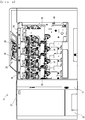
- the image forming apparatus 10 includes a housing 11 (an example of the apparatus main body).
- the housing 11 has an approximately parallelepiped shape as a whole. Some of the components constituting the image forming apparatus 10 are stored in the housing 11. It is noted that FIG. 1 shows a state where a cover covering the right side of the housing 11 has been removed.
- the image forming apparatus 10 includes a plurality of image forming units 15 (15Y, 15C, 15M, and 15K), an intermediate transfer unit 16, a laser scanning device 17, a primary transfer roller 18, a secondary transfer roller 19, a fixing device 20, a sheet tray 21, the sheet feed cassette 22, a conveyance path 24, and a control board 26 configured to control the portions of the image forming apparatus 10.
- the image forming apparatus 10 includes toner containers 3 (see FIG. 1 ) that have been attached to the inside of the housing 11 in a detachable manner.
- the image forming apparatus 10 includes four image forming units 15.
- FIG. 3 is a cross-sectional view of a central portion of an image forming unit 15.
- the image forming unit 15 forms a toner image by the electrophotography.
- each of the image forming units 15 includes a drum unit 31, a charging device 32, and a developing device 33.
- the image forming units 15 are arranged in alignment along the front-rear direction D2 in the housing 11, and form a color image based on the so-called tandem system.
- the image forming unit 15Y is configured to form a toner image of yellow.
- the image forming units 15C, 15M and 15K are configured to form toner images of cyan, magenta and black, respectively.
- the image forming units 15Y for yellow, 15C for cyan, 15M for magenta, and 15K for black are arranged in alignment in the stated order from the downstream side in the running direction (the direction indicated by the arrow D10) of a transfer belt 35 of the intermediate transfer unit 16.
- the drum unit 31 includes a photoconductor drum 41, a drum cleaning device 42 (an example of the drum cleaning portion), a discharge guide portion 43 (see FIG. 15 ), and a housing 44 that supports these components.
- the housing 44 is elongated in the left-right direction D3.
- the photoconductor drum 41 has a cylindrical shape and carries a toner image developed by the developing device 33.
- the photoconductor drum 41 is rotatably supported by the housing 44.
- the charging device 32 uniformly charges the photoconductor drum 41 to a certain potential.
- the laser scanning device 17 irradiates a laser beam on the surface of the photoconductor drum 41 based on the image data.
- electrostatic latent images are formed on the surfaces of the photoconductor drums 41, respectively.
- the electrostatic latent images are developed (visualized) as toner images by the developing devices 33, respectively.
- the toner images of respective colors formed on the surfaces of the photoconductor drums 41 are transferred to the transfer belt 35 by the primary transfer roller 18 such that the toner images are overlaid with each other in sequence.
- the color image on the transfer belt 35 is transferred by the secondary transfer roller 19 to a print sheet.
- the color image transferred to the print sheet is fixed to the print sheet by the fixing device 20, and thereafter, the print sheet is discharged from a sheet discharge port 28 to the sheet tray 21.
- the drum cleaning device 42 is configured to remove toner that has remained on the photoconductor drum 41 after the transfer.
- the drum cleaning device 42 is disposed on the rear side of the photoconductor drum 41.
- the drum cleaning device 42 is provided for each photoconductor drum 41.
- the drum cleaning device 42 includes a cleaning blade 45 that is a cleaning member, and a spiral member 46.
- the cleaning blade 45 and the spiral member 46 are elongated in the left-right direction D3.
- the cleaning blade 45 and the spiral member 46 are supported by the housing 44.
- the cleaning blade 45 has approximately the same length as the photoconductor drum 41.
- the tip of the cleaning blade 45 is disposed so as to be in contact with or close to the surface of the photoconductor drum 41.
- the spiral member 46 is a toner conveyance member having a spiral blade around a shaft.
- the spiral member 46 is rotatably supported in the housing 44.
- the spiral member 46 is rotated when a rotational driving force is input to its shaft. While the photoconductor drum 41 is rotated, the cleaning blade 45 removes toner that has remained on the surface of the photoconductor drum 41 after the transfer by the primary transfer roller 18. The removed toner is to be discarded later, and thus called waste toner in general.
- the waste toner is conveyed toward a certain direction by the rotating spiral member 46. Specifically, the waste toner is conveyed toward one side (in the present embodiment, the right side) in the axis direction (longitudinal direction) of the photoconductor drum 41.
- the discharge guide portion 43 is disposed at the right end of the housing 44.
- the waste toner is guided downward by the discharge guide portion 43, passes through a discharge port 431 (see FIG. 15 ) that is described below, and is discharged to a lower storage portion 72 of the toner container 3. It is noted that the discharge guide portion 43 is described below.
- the developing device 33 includes a housing 50, a first stirring member 52, a second stirring member 53, and a developing roller 54.
- Toner developer
- a supply port 56 is formed in a wall 51 of the housing 50 that is located above the first stirring member 52.
- the supply port 56 is formed at the right end of the wall 51.
- the toner discharged from the toner container 3 is supplied from the supply port 56 into the housing 50.
- the developing roller 54 draws up the toner from the second stirring member 53 by the magnetic pole embedded therein, and carries the toner on its circumferential surface.
- the toner held on the developing roller 54 is caused to adhere to the electrostatic latent image on the photoconductor drum 41 by the potential difference applied to between the developing roller 54 and the photoconductor drum 41.
- a plurality of toner containers 3 are attached to the inside of the housing 11. Specifically, the four toner containers 3 are respectively attached to attachment portions 58 (see FIG. 4 ) provided in the inside of the housing 11.
- a plurality of toner containers 3 are attached in a state of being aligned along the front-rear direction D2, and a toner container 3K for black is disposed at the rear-most position.
- Each of the toner containers 3 includes an upper storage portion 71 (an example of the first toner storage portion) and a lower storage portion 72 (an example of the second toner storage portion).
- the upper storage portion 71 includes, inside thereof, a storage space 85 (see FIG. 6 ) for storing toner, and unused toner for supply is stored in the storage space 85.
- the lower storage portion 72 includes, inside thereof, a storage space 86 (see FIG. 6 ) for storing toner, and the waste toner discharged from the drum cleaning device 42 is stored in the storage space 86.
- the unused toner is supplied to the insides of the developing devices 33 from the upper storage portions 71 of the toner containers 3.
- waste toner discharged from the drum cleaning devices 42 passes through the discharge guide portions 43 (see FIG. 15 ), and is stored in the lower storage portions 72 of the toner containers 3.
- the four toner containers 3 are located at the right side of the image forming units 15 inside a right-side cover (not shown) of the housing 11.
- the toner containers 3 are arranged on the right side of the housing 11 in alignment along the front-rear direction D2. The toner containers 3 are described in detail below.
- the intermediate transfer unit 16 is provided above the four image forming units 15. More specifically, the intermediate transfer unit 16 is provided above the photoconductor drums 41.
- the intermediate transfer unit 16 includes the transfer belt 35, a driving roller 36, a driven roller 37, a belt cleaning device 38 (an example of the belt cleaning portion), and a relay guide portion 39 (see FIG. 15 ). It is noted that the primary transfer roller 18 is supported by a frame (not shown) of the intermediate transfer unit 16.
- the transfer belt 5 an annular belt member, is suspended between the driving roller 36 and the driven roller 37 so as to extend in the front-rear direction D2.
- a plurality of drum units 31 are arranged in alignment in the front-rear direction D2 along the transfer belt 35.
- the transfer belt 35 holds, on its surface, toner images primarily transferred from the photoconductor drums 41.
- the transfer belt 35 is rotationally driven and moves in a direction indicated by the arrow D10, the toner images of respective colors carried by the photoconductor drums 41 are transferred to the transfer belt 35 such that the toner images are overlaid with each other in sequence.
- the belt cleaning device 38 is disposed in the vicinity of the fixing device 20. Specifically, the belt cleaning device 38 is provided above the transfer belt 35 in the rear side of the housing 11. Below the belt cleaning device 38, the image forming unit 15K, which is an image forming unit 4 for black, is disposed. That is, the belt cleaning device 38 is located closest to the image forming unit 15K for black among the plurality of image forming units 4.
- the belt cleaning device 38 is configured to remove the waste toner that has remained on the surface of the transfer belt 35, and convey the removed waste toner toward the lower storage portion 72 of the toner container 3K.
- the belt cleaning device 38 includes a cleaning roller 381 that is elongated in the left-right direction D3, a spiral member 382 as a conveyance member for conveying the waste toner, and a housing 383 for storing these components (see FIG. 2 ).
- the cleaning roller 381 is configured to remove the waste toner from the surface of the transfer belt 35 by rotating while in contact with the surface of the transfer belt 35.
- the used toner thus removed (hereinafter referred to as "waste toner") is conveyed in a certain direction by the spiral member 382 as it rotates. Specifically, the waste toner is conveyed toward one side in the width direction (a direction that matches the left-right direction D3) of the transfer belt 35 (in the present embodiment, conveyed toward the right side).
- the relay guide portion 39 is provided at the right end of the housing 383.
- the waste toner is guided downward by the relay guide portion 39, passes through a discharge guide portion 43K of a drum unit 31K disposed at the rear-most position, and is conveyed to the lower storage portion 72 of the toner container 3K. It is noted that the relay guide portion 39 is described below.
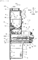
- FIG. 15 is a partial enlarged diagram showing a cross-sectional structure of a right-end portion of the drum units 31 of the image forming units 15.
- FIG. 15 shows cross-sectional structures of the drum unit 31M for magenta and the drum unit 31K for black.
- a developing device 33 corresponding to the drum unit 31K is represented by a dotted line.
- a discharge guide portion 43M is provided at the right end of the housing 44 of the drum unit 31M. That is, the discharge guide portion 43M is provided in the drum unit 31M. It is noted that a discharge guide portion 43 having the same structure as the discharge guide portion 43M is provided in each of the drum units 31 for yellow and cyan.
- the discharge guide portion 43M guides the waste toner that has been removed by the drum cleaning device 42 in the drum unit 31M and conveyed to the right end of the housing 44, to an inlet 114 of the lower storage portion 72 of the toner container 3M.
- An inner space of the discharge guide portion 43M is a passage 117 in which the waste toner passes.
- the discharge guide portion 43M extends diagonally downward from above, and the discharge port 431 connected to the inlet 114 is formed at a lower end of the discharge guide portion 43M.
- a right end portion 461 of the spiral member 46 is disposed in the passage 117.
- the end portion 461 is rotatably supported by the discharge guide portion 43M.
- the spiral member 46 rotates, and the waste toner is conveyed to the passage 117 of the discharge guide portion 43M.
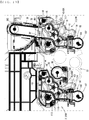
- two paddle portions 118 and 119 are provided in a region from the end portion 461 to the discharge port 431.
- the rotation shaft of each of the paddle portions 118 and 119 is rotatably supported by the discharge guide portion 43M.
- the rotational driving force of the spiral member 46 is transmitted to the paddle portions 118 and 119 via a gear transmission mechanism (not shown).
- the spiral member 46 When the spiral member 46 is rotated, its rotational driving force is transmitted to the paddle portions 118 and 119 via the gear transmission mechanism, and the paddle portions 118 and 119 are rotated.
- the waste toner that has been conveyed to the passage 117 is conveyed in the passage 117 to the discharge port 431 by the paddle portions 118 and 119, is further passed through the inlet 114 and a first conveyance guide portion 94 (an example of the first guide portion) of the toner container 3M, and guided into the lower storage portion 72 of the toner container 3M.
- a first conveyance guide portion 94 an example of the first guide portion
- a discharge guide portion 43K is provided at the right end of the housing 44 of the drum unit 31K. That is, the discharge guide portion 43K is provided in the drum unit 31K.
- the discharge guide portion 43K guides the waste toner that has been removed by the drum cleaning device 42 in the drum unit 31K and conveyed to the right end of the housing 44, to the inlet 114 of the lower storage portion 72 of the toner container 3K.
- the discharge guide portion 43K and the discharge guide portion 43M have some components in common. As a result, the components common to these portions are assigned the same reference signs, and description thereof is omitted.
- the discharge guide portion 43K differs from the discharge guide portion 43M in that a receiving port 120 is formed at the top of the discharge guide portion 43K.
- the receiving port 120 is an opening from which the waste toner dischared from the belt cleaning device 38 is received.
- the receiving port 120 is connected to a discharge port 391 of the relay guide portion 39 that is described below.
- the waste toner that has entered the receiving port 120 is guided to the inlet 114 of the lower storage portion 72 of the toner container 3K by the discharge guide portion 43K, together with the waste toner discharged from the drum cleaning device 42.
- the relay guide portion 39 is provided at the right end of the belt cleaning device 38.
- the relay guide portion 39 guides the waste toner that has been conveyed to the right end of the housing 383 through the belt cleaning device 38 by the spiral member 382, to the discharge guide portion 43K.
- the discharge port 391 is formed in a lower portion of the relay guide portion 39, and the discharge port 391 is connected to the receiving port 120 of the discharge guide portion 43K.
- the waste toner guided to the receiving port 120 passes through the discharge guide portion 43K, is conveyed further downward by the paddle portions 118 and 119, passes through the discharge port 431, the inlet 114, and a second conveyance guide portion 107 (an example of the second guide portion) of the toner container 3K, and is guided into the lower storage portion 72 of the toner container 3K.
- each attachment portion 58 for supporting the toner containers 3 in a detachable manner is provided at the right end of the housing 11.
- the attachment portions 58 are fixed to a support plate 49 provided at the right end of the housing 11.
- Each attachment portion 58 includes a bracket 59 for supporting a corresponding toner container 3.
- the toner containers 3 are supported by corresponding brackets 59 in a detachable manner.
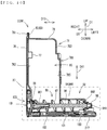
- FIG. 5 and FIG. 6 show the toner container 3M and the toner container 3K disposed next to the toner container 3M.
- the toner container 3K is larger in outer shape and capacity than the toner container 3M since the toner container 3K stores black toner that is used much, but except for this, they have approximately the same configuration.
- components of the toner container 3K that are the same as those of the toner container 3M are assigned the same reference signs, and description thereof is omitted.
- the toner containers 3Y and 3C have the same configuration as the toner container 3M, thus description thereof is omitted.
- the drawings show the up-down direction D1, the front-rear direction D2 and the left-right direction D3 based on an attachment attitude of the toner containers 3M and 3K attached to the attachment portions 58 (see FIG. 4 ).
- the up-down direction D1 is defined as a height direction D11 of the toner containers 3M and 3K
- the front-rear direction D2 is defined as a width direction D12 of the toner containers 3M and 3K
- the left-right direction D3 is defined as a depth direction D13 of the toner containers 3M and 3K.
- the toner container 3M includes a container main body 75.
- the container main body 75 is a resin product formed by injection molding a synthetic resin.
- the container main body 75 is elongated in the height direction D11, broad in the width direction D12, and shallow in the depth direction D13.
- the container main body 75 includes an upper case 78 (an example of the first housing) formed in the upper side thereof, a lower case 79 (an example of the second housing) formed in the lower side thereof, and a lid member 76 (an example of the lid member). That is, the upper case 78 is formed in one side (upper side) of the container main body 75 in the height direction D11 (longitudinal direction), and the lower case 79 is formed in the other side (lower side) of the container main body 75 in the height direction D11 (longitudinal direction).
- the upper case 78 and the lower case 79 are integrally formed as the container main body 75.
- the storage space 85 for storing the unused toner is defined.
- the storage space 85 in the upper storage portion 71 is defined by the upper case 78.
- the storage space 86 for storing the waste toner is defined in the lower case 79. That is, the storage space 86 in the lower storage portion 72 is defined by the lower case 79.
- the upper case 78 and the lower case 79 are separated from each other in the up-down direction D1, and a gap 88 (see FIG. 7 ) having a predetermined distance is formed between the upper case 78 and the lower case 79.
- the upper case 78 includes a bottom wall 782 that constitutes the bottom wall surface thereof and is formed in an arc shape
- the lower case 79 includes a top wall 792 that constitutes the top wall surface thereof.
- the gap 88 is formed between the bottom wall 782 and the top wall 792.
- the bottom wall 782 and the top wall 792 are an example of the pair of walls that are separated from each other in the height direction D11.
- An opening portion 81 is formed in the right side surface of the upper case 78, and an opening portion 82 is formed in the right side surface of the lower case 79.
- the opening portions 81 and 82 are formed on the same plane.
- a flange 83 is formed along opening edges of the opening portions 81 and 82.
- the flange 83 is formed in the shape of a plate having a thickness in the depth direction D13.
- the flange 83 includes a peripheral flange 831 and a central flange 832 (an example of the coupling member and the common flange).
- the peripheral flange 831 is formed around the outer periphery of the right side surface of the container main body 75.
- the central flange 832 is, as shown in FIG.
- the central flange 832 is continued from the lower edge of the opening portion 81 to the upper edge of the opening portion 82.
- the central flange 832 is a flange common to the opening portion 81 and the opening portion 82.
- the bottom wall 782 and the top wall 792 extend from the central flange 832 in the depth direction D13.
- the lid member 76 is a resin product formed by injection molding a synthetic resin. As shown in FIG. 5 , the lid member 76 covers the opening portion 81 and the opening portion 82.
- the lid member 76 is a flat plate-like member and is formed in the shape that matches the peripheral shape of the flange 83. In a state where an outer periphery 761 of the lid member 76 is aligned with the flange 83, the outer periphery 761 and the flange 83 are welded.
- the upper storage portion 71 having the storage space 85 and the lower storage portion 72 having the storage space 86 are provided.
- a portion around the gap 88 is smaller in strength than the other portions.
- the toner container 3M can be easily bent at the vicinity of the gap 88 in the width direction D12 and in the depth direction D13, and can be easily bent in the rotation direction around the height direction D11 as the axis of rotation.
- a plate-like reinforcing rib 751 is disposed between the bottom wall 782 of the upper case 78 and the top wall 792 of the lower case 79.
- the reinforcing rib 751 extends in the depth direction D13 vertically from the central flange 832.
- the reinforcing rib 751 coupled with the bottom wall 782 and the top wall 792, is a plate-like member having a thickness in the width direction D12.
- the left-end surface of the reinforcing rib 751 is inclined diagonally upward left from the top wall 792 to the bottom wall 782, and more specifically, inclined in a curved shape.
- the reinforcing rib 751 as such, the strength at the vicinity of the gap 88 between the upper storage portion 71 and the lower storage portion 72 is reinforced. As a result, the toner container 3M is prevented from being excessively bent at the vicinity of the gap 88, in particular, prevented from being excessively bent in the depth direction D13.
- the lower storage portion 72 of the toner container 3M is larger in size in the depth direction D13 than the upper storage portion 71. That is, the size in the depth direction D13 of the lower storage portion 72 of the toner container 3M is larger than that of the upper storage portion 71.
- the size in the height direction D11 of the upper storage portion 71 is larger than that of the lower storage portion 72, and the upper storage portion 71 and the lower storage portion 72 have approximately the same size in the width direction D12. In the configuration where the upper storage portion 71 and the lower storage portion 72 are separate in the up-down direction D1, there may be a case where each of the upper storage portion 71 and the lower storage portion 72 cannot secure an enough capacity for storing toner.
- the upper storage portion 71 includes a stirring member 91 (an example of the third rotating member) and a first conveyance portion 92.
- a paddle-like stirring member 91 is provided in the upper storage space 85.
- the stirring member 91 is supported by the upper case 78 so as to be rotatable in the storage space 85.
- the first conveyance portion 92 for conveying toner to the developing device 33 is provided in the storage space 85.
- the first conveyance portion 92 includes a first conveyance guide portion 94 and a spiral member 95, wherein the first conveyance guide portion 94 is cylindrical and extends outward from a wall surface 781 (an example of the facing surface) of the left side of the upper case 78, and the spiral member 95 (an example of the first rotating member, see FIG. 10 ) is provided in the inside of the first conveyance guide portion 94.
- the first conveyance guide portion 94 is integrally formed with the upper case 78 in the shape of a cylinder whose center is the same as the rotation center of the spiral member 95.
- the wall surface 781 is located in one side of the toner container 3M with respect to the attachment portion 58 in the depth direction D13, and is a surface that faces the attachment portion 58 when the toner container 3M is attached to the attachment portion 58. It is noted that the depth direction D13 matches the direction in which the toner container 3M is attached to and detached from the attachment portion 58.
- the spiral member 95 is rotatably provided in the upper storage portion 71, and as shown in FIG. 10 , extends in the depth direction D13 that is perpendicular to the height direction D11.
- the spiral member 95 is a conveyance member that conveys the unused toner in the storage space 85 toward the attachment portion 58 (see FIG. 4 ) through the inside of the first conveyance guide portion 94.
- the first conveyance guide portion 94 is a guide member that guides the unused toner conveyed by the spiral member 95 to the developing device 33.
- the spiral member 95 includes blades 97 of a spiral shape around a rotation shaft 96.
- An end portion 961 (an example of the first end portion) of the rotation shaft 96 of the spiral member 95 on the lid member 76 side is rotatably supported by a bearing portion 99 (an example of the first bearing portion) that is integrally formed with an inner surface 762 of the lid member 76.
- the opposite end of the rotation shaft 96 is rotatably supported by the first conveyance guide portion 94.
- a first input portion 98 (an example of the first drive input portion and the second input joint) is integrally formed with an end portion 962 that is the opposite end of the rotation shaft 96, wherein the first input portion 98 receives a rotational driving force input from outside.
- a through hole 941 is formed in the tip of the first conveyance guide portion 94. In the state where the first input portion 98 projects from the through hole 941 to the outside, the end portion 962 is rotatably supported by the through hole 941.
- FIG. 14 is an enlarged view of a main part X1 that is enclosed by a two-dot chain line in FIG. 10 .
- the end portion 961 of the rotation shaft 96 (an example of the first rotation shaft) includes an inner hole 178 that extends along the axial direction from an end surface of the rotation shaft 96 on the lid member 76 side toward the opposite side. That is, the end portion 961 is a cylinder portion formed in a cylindrical shape so as to have the inner hole 178 in its inside.
- the inner hole 178 is formed in a size that allows a first coupling portion 1912 of a first transmission portion 191 described below to be inserted therethrough.
- an arc-shaped support portion 179 On an end surface of the end portion 961 on the lid member 76 side, an arc-shaped support portion 179 whose outer diameter is larger than the inner hole 178 is formed.
- an engagement opening 9611 (an example of the first engagement opening) is formed on an outer circumferential surface of the end portion 961, wherein a first engaging portion 197 described below is engaged with the engagement opening 9611 when the first coupling portion 1912 described below is inserted through the inner hole 178.
- the engagement opening 9611 penetrates to the inner hole 178 of the end portion 961.
- the bearing portion 99 is provided on the inner surface 762 of the lid member 76.
- the bearing portion 99 includes a boss 180 (an example of the first boss) that projects vertically from the inner surface 762 of the lid member 76.
- the boss 180 is inserted in the support portion 179 of the end portion 961 such that the end portion 961 is supported by the boss 180.
- a through hole 181 is formed at the center of a projection end of the boss 180, wherein the first coupling portion 1912 of the first transmission portion 191 described below can be inserted through the through hole 181.
- a toner discharge port 100 is formed in the upper case 78 so that toner stored in the storage space 85 can be discharged from the toner discharge port 100 to outside.
- the toner discharge port 100 is formed in a lower part of an outer circumferential surface (hereinafter merely referred to as a lower surface) of the first conveyance guide portion 94.
- the toner discharge port 100 is a through-opening that penetrates, vertically downward, an outer circumferential wall constituting the lower surface of the first conveyance guide portion 94.
- the toner discharge port 100 is formed in an approximately square shape.
- the toner discharge port 100 is formed in an end portion of the lower surface of the first conveyance guide portion 94 at a position closest to the first input portion 98.
- a shutter member 101 (an example of the opening and closing member) for opening and closing the toner discharge port 100 is provided on the lower surface of the first conveyance guide portion 94.
- the shutter member 101 is supported by the first conveyance guide portion 94 in such a manner that the shutter member 101 can slide the lower surface of the first conveyance guide portion 94 in the longitudinal direction (the left-right direction of FIG. 10 ) of the first conveyance guide portion 94.
- the shutter member 101 when the toner container 3M is attached to the attachment portion 58 (see FIG. 4 ), the shutter member 101 is moved from a closing position of closing the toner discharge port 100, to an opening position of opening the toner discharge port 100.
- the attachment portion 58 includes a projection piece 581 which is configured to press an end portion 1011 of the shutter member 101 when the toner container 3M is attached to the attachment portion 58.
- the projection piece 581 presses the end portion 1011 of the shutter member 101 in an opposite direction to the attachment direction, causing the shutter member 101 to be moved from the closing position to the opening position.
- the projection piece 581 is hooked to the end portion 1011 of the shutter member 101 during the removal operation, causing the shutter member 101 to be moved from the opening position to the closing position.
- the toner discharge port 100 is aligned with the supply port 56 of the developing device 33 for positioning, then the toner discharge port 100 is connected to the supply port 56 so that toner can be supplied from the toner discharge port 100 to the supply port 56.
- the first input portion 98 is coupled with a first output joint 61 (an example of the drive output portion and the first drive coupling portion, see FIG. 13 ) that is provided in the attachment portion 58, and a rotational driving force output from a drive source such as a motor is transmitted to the first input portion 98.
- the spiral member 95 Upon receiving the rotational driving force, the spiral member 95 is rotated, and the toner in the storage space 85 is conveyed from the toner discharge port 100 to the supply port 56 via the first conveyance guide portion 94, and is supplied to the inside of the developing device 33.
- an engagement hole 611 which is rectangular in a cross section (see FIG. 13 ) is formed in the first output joint 61.
- the first input portion 98 is inserted in the engagement hole 611 such that the first output joint 61 is engaged with the first input portion 98 in a direction of rotation around the axis. This allows the rotational driving force received from the first output joint 61 to be transmitted to the first input portion 98.
- the first input portion 98 is an example of the engaging portion.
- the first output joint 61 is provided in the attachment portion 58.
- the first output joint 61 is a drive output portion configured to output the rotational driving force that is output from a drive source such as a motor provided in the image forming apparatus 10, to the outside.
- the first output joint 61 is coupled with the first input portion 98 in the left-right direction D3 when the toner container 3M is attached to the attachment portion 58.
- the attachment portion 58 includes a sponge member 582 (an example of the collection member) below the first output joint 61.
- the sponge member 582 is a porous, flexible resin member having elasticity.
- the sponge member 582 is formed in a rectangular parallelepiped shape.
- the sponge member 582 passes a second opening portion 218 of a film member 217 (see FIG. 14 ) in the state where the sponge member 582 is contracted while being pressed against a lower surface of the film member 217 of a support plate 102 described below.
- the sponge member 582 is slid while pressing the lower surface of the film member 217 (see FIG. 14 ).
- the sponge member 582 is slid while pressing the lower surface of the film member 217 (see FIG. 14 ).
- the sponge member 582 is slid while pressing the lower surface of the film member 217 (see FIG. 14 ).
- the sponge member 582 may be replaced with an elastic member that can hold toner in its inside.
- a gear transmission mechanism 103 (an example of the transmission mechanism) is provided in the lid member 76.
- the gear transmission mechanism 103 is coupled with the rotation shaft 96 of the spiral member 95 and with a rotation shaft member 911 of the stirring member 91 in the state where the lid member 76 closes the opening portions 81 and 82.
- the rotational driving force transmitted from the first input portion 98 to the spiral member 95 is transmitted to the stirring member 91 by the gear transmission mechanism 103. That is, with the provision of the gear transmission mechanism 103, when the rotational driving force is input to the first input portion 98, the spiral member 95 and the stirring member 91 are rotated interlocking with each other.
- the first conveyance portion 92 includes the support plate 102, as well as the above-described first conveyance guide portion 94 and shutter member 101.
- the support plate 102 supports, on its upper surface, the shutter member 101 in such a manner that the shutter member 101 can move between the closing position and the opening position (position shown in FIG. 14 ) in the depth direction D13.
- the first conveyance guide portion 94 includes a bottom portion 943 and a cylindrical cylinder portion 944, wherein the bottom portion 943 constitutes a lower surface of the first conveyance guide portion 94, and the cylinder portion 944 is integrally formed with the bottom portion 943 so as to be located above the bottom portion 943.
- the bottom portion 943 is formed in a shape of a plate extending in the depth direction D13.
- the support plate 102 is provided independently of the first conveyance guide portion 94, and is attached to the bottom portion 943 in such a way as to face the lower surface of the bottom portion 943. It is noted that the toner discharge port 100 is formed in the bottom portion 943 so as to penetrate to an inside of the cylinder portion 944.
- the support plate 102 is attached to the bottom portion 943 in a state where a gap 210 is formed between the support plate 102 and the bottom portion 943.
- the shutter member 101 is disposed in the gap 210 between the support plate 102 and the bottom portion 943 so as to be movable in the depth direction D13.
- a first opening portion 211 (an example of the opening portion) having a larger size than the toner discharge port 100 is formed.
- the first opening portion 211 is formed in the support plate 102 at a position near an end portion 1021 in the first input portion 98 side. In the present embodiment, the first opening portion 211 is located below the toner discharge port 100.
- the support plate 102 for supporting the shutter member 101 is required in the toner container 3M, and the support plate 102 needs the first opening portion 211 through which to pass the toner discharged from the toner discharge port 100.
- the toner discharged from the toner discharge port 100 passes through the first opening portion 211 and is supplied to the developing device 33 of the image forming apparatus 10.
- the toner adheres to a peripheral edge of the first opening portion 211 when the toner is supplied.
- the shutter member 101 moves from the opening position to the closing position.
- the shutter member 101 moves to the closing position, the shutter member 101 is interposed between the toner discharge port 100 and the first opening portion 211, and the toner discharge port 100 is closed by the shutter member 101.
- the shutter member 101 is not disposed below the first opening portion 211.
- the toner container 3M of the present embodiment includes the film member 217 as described below, and this makes it possible to prevent the toner from falling off from the peripheral edge of the toner discharge port 100.
- the support plate 102 includes the film member 217.
- the film member 217 is, for example, a microcell polymer sheet formed from a highly functional urethane foam having a high-density, ultra-fine, and uniform cell structure.
- the film member 217 is, for example, approximately 0.2 mm to 0. 25 mm in thickness.
- the film member 217 may be formed from a material other than the microcell polymer sheet.
- the film member 217 is attached to the support plate 102 in such a way as to cover the first opening portion 211. Specifically, the film member 217 is stuck to a lower surface of the support plate 102 by adhesive or the like. By this way, the film member 217 is fixed to the support plate 102.
- the film member 217 has the second opening portion 218 of a square shape at a position corresponding to the toner discharge port 100.
- the second opening portion 218 is formed in the same size as the toner discharge port 100. That is, the toner discharge port 100 and the second opening portion 218 are disposed so as to face each other in the height direction D11, and when the support plate 102 is viewed from below, the toner discharge port 100 and the second opening portion 218 overlap each other.
- a third opening portion 213 is formed in the shutter member 101.
- the third opening portion 213 is formed in the same size as the toner discharge port 100 and the second opening portion 218.
- the third opening portion 213 when the shutter member 101 is at the opening position, the third opening portion 213 is located between the toner discharge port 100 and the second opening portion 218.
- the third opening portion 213 moves from the toner discharge port 100 and the second opening portion 218 to a position on the end portion 1021 side (the right side in FIG. 14 ). By this way, the toner discharge port 100 is closed by the shutter member 101.
- a frame edge portion 214 is integrally formed with a lower surface of the shutter member 101.
- the frame edge portion 214 projects downward from a peripheral edge portion of the third opening portion 213 to a position lower than the lower surface of the shutter member 101 and surrounds the circumference of the third opening portion 213.
- a lower end of the frame edge portion 214 slides on an upper surface of the film member 217.
- the support plate 102 supports the shutter member 101 such that the lower end of the frame edge portion 214 slides on the upper surface of the film member 217 when the shutter member 101 is moved from the opening position to the closing position.
- a seal member 221 is provided in the gap 210 between the bottom portion 943 and the support plate 102.
- the seal member 221 is formed from, for example, a resin member such as a flexible urethane foam having elasticity.
- the seal member 221 is provided on the bottom portion 943 at a peripheral edge of the toner discharge port 100.
- the seal member 221 is stuck to the lower surface of the bottom portion 943 by an adhesive or the like in such a way as to surround the circumference of the toner discharge port 100. By this way, the seal member 221 prevents toner from leaking from the toner discharge port 100.
- the seal member 221 biases the shutter member 101 downward by the elasticity in the state where the shutter member 101 is disposed between the toner discharge port 100 and the film member 217.
- the frame edge portion 214 provided on the shutter member 101 is always pressed against the upper surface of the film member 217 when the shutter member 101 moves between the closing position and the opening position.
- no gap is generated between the frame edge portion 214 and the film member 217, and toner leakage from between the frame edge portion 214 and the film member 217 is prevented.
- a sponge member 222 is provided in the gap 210.
- the sponge member 222 is disposed in a region of the gap 210 on the lid member 76 side.
- the gap 210 has a region in which the shutter member 101 is not disposed, and the sponge member 222 is provided in this region.
- the sponge member 222 is stuck to the lower surface of the bottom portion 943 by an adhesive or the like.
- the sponge member 222 is larger than the gap 210 in thickness in the height direction, and is disposed in the gap 210 in a contracted state. By this way, in the gap 210, the sponge member 222 stops toner from moving toward the lid member 76 (the left side in FIG. 14 ).
- a through opening 219 is formed in the lower surface of the support plate 102.
- the through opening 219 is provided at a position that is separated from the first opening portion 211 toward the lid member 76 in the support plate 102. That is, the through opening 219 is provided on the lower surface of the support plate 102 at a position that is separated from the first opening portion 211 by a predetermined distance in a direction away from the attachment portion 58 (leftward in FIG. 14 ).
- the through opening 219 penetrates the support plate 102.
- the shutter member 101 is disposed in such a way as to seal an opening of the through opening 219 on the gap 210 side.
- the shutter member 101 closes the through opening 219.
- the support plate 102 supports the shutter member 101 on its upper surface such that the shutter member 101 can move between the closing position and the opening position.
- the shutter member 101 does not receive friction from the upper surface of the support plate 102.
- the shutter member 101 can move smoothly on the upper surface of the support plate 102.
- the through opening 219 may be formed at such a position where the sponge member 582 of the attachment portion 58 enters the through opening 219 while the toner container 3M is in the attachment attitude of being completely attached to the attachment portion 58.
- the through opening 219 has a role of a retreat port for the sponge member 582 while the toner container 3M is in the attachment attitude.
- the amount by which the sponge member 582 is contracted when it is pressed against the film member 217 is set for it to be contracted as much as the depth of the through opening 219. By this way, upon entering the through opening 219, the sponge member 582 is restored to the original state.
- the configuration reduces the possibility that the toner adhered to the edge portion of the second opening portion 218 may fall off and smear other members when the toner container 3M is removed from the attachment portion 58.
- the sponge member 582 is provided in the attachment portion 58, the small amount of toner that has adhered to the second opening portion 218 is collected by the sponge member 582 in a reliable manner when the toner container 3M is removed from the attachment portion 58.
- the shutter member 101 can move smoothly on the upper surface of the support plate 102.
- the support plate 102 can bend in the vicinity of the through opening 219. This prevents the support plate 102 from being damaged or deformed by an excessive force.
- the sponge member 582 is not always in a contracted state, but is restored to its original state while the toner container 3M is in the attachment attitude of being attached to the attachment portion 58, it is possible to prevent the sponge member 582 from being fixed in a contracted state.
- the lower storage portion 72 includes a second conveyance portion 105.
- the second conveyance portion 105 for conveying the waste toner discharged from a drum unit 31 for magenta to the inside of the storage space 86 is provided in the storage space 86.
- the second conveyance portion 105 includes a second conveyance guide portion 107 and a spiral member 108, wherein the second conveyance guide portion 107 is cylindrical, extends outward from a wall surface 791 of the left side of the lower case 79, and includes a toner conveyance path in its inside, and the spiral member 108 (an example of the second rotating member, the rotating member, and the first conveyance member, see FIG. 11 ) is provided in the inside of the second conveyance guide portion 107.
- the second conveyance guide portion 107 is integrally formed with the lower case 79.
- the spiral member 108 is rotatably provided in the inside of the lower storage portion 72, and as shown in FIG. 11 , extends in the depth direction D13 perpendicular to the height direction D11.
- the spiral member 108 is a conveyance member that conveys the waste toner that has been discharged from the drum unit 31 to the second conveyance guide portion 107, to the storage space 86 through the inside of the second conveyance guide portion 107.
- the second conveyance guide portion 107 is a guide member that receives the waste toner from the drum unit 31, and guides the waste toner conveyed by the spiral member 108 to the inside of the storage space 86.
- the spiral member 108 includes spiral blades 110 around a rotation shaft 109.
- An end portion 1091 (an example of the second end portion) of the rotation shaft 109 of the spiral member 108 on the lid member 76 side is rotatably supported by a bearing portion 112 (an example of the second bearing portion) that is integrally formed with the inner surface 762 of the lid member 76.
- the opposite end of the rotation shaft 109 is rotatably supported by the second conveyance guide portion 107.
- a second input portion 111 (an example of the second drive input portion and the first input joint) is attached to an opposite end portion 1092 of the rotation shaft 109, wherein the second input portion 111 receives a rotational driving force input from outside.
- the inlet 114 for guiding the waste toner to the inside of the storage space 86 is formed on the upper surface of the second conveyance guide portion 107.
- a shutter member 115 for opening and closing the inlet 114 is provided on the upper surface of the second conveyance guide portion 107.
- the shutter member 115 is supported by the second conveyance guide portion 107 such that the upper surface of the second conveyance guide portion 107 can be slid in the longitudinal direction (the left-right direction of FIG. 11 ) of the second conveyance guide portion 107.
- the shutter member 115 is moved from a closing position of closing the inlet 114, to an opening position of opening the inlet 114.
- the inlet 114 is aligned with the discharge port 431 of the discharge guide portion 43 for positioning, then the inlet 114 is connected to the discharge port 431 so that waste toner can be conveyed from the discharge port 431 to the inlet 114.
- the second input portion 111 is coupled with a second output joint 62 (an example of the drive output portion and the first drive coupling portion, see FIG. 13 ) that is provided in the attachment portion 58, and a rotational driving force output from a drive source such as a motor is transmitted to the second input portion 111.
- the spiral member 108 Upon receiving the rotational driving force, the spiral member 108 is rotated, and the waste toner that has been discharged from the discharge port 431 and conveyed into the second conveyance guide portion 107 is conveyed to the storage space 86 through the second conveyance guide portion 107.
- the second output joint 62 is provided in the attachment portion 58, at a position different from the first output joint 61.
- the second output joint 62 is a drive output portion configured to output the rotational driving force that is output from a drive source such as a motor provided in the image forming apparatus 10, to the outside.
- the second output joint 62 is coupled with the second input portion 111 in the left-right direction D3 when the toner container 3M is attached to the attachment portion 58.
- the central flange 832 is provided so as to couple the upper case 78 of the upper storage portion 71 with the lower case 79 of the lower storage portion 72.
- the toner container 3M can be bent at the vicinity of the gap 88 when the toner container 3M is attached to the attachment portion 58, so that the first input portion 98 is aligned with the first output joint 61, and the second input portion 111 is aligned with the second output joint 62 for positioning.
- the first conveyance portion 92 and the second conveyance portion 105 are separated from each other in the width direction D12.
- the first conveyance portion 92 is provided on the wall surface 781 of the upper storage portion 71 at a position close to a side portion on one side (the front side) in the width direction D12.
- the second conveyance portion 105 is provided on the wall surface 791 of the lower storage portion 72 at a position close to a side portion on the opposite side (the rear side) in the width direction D12.
- the toner container 3M includes a gripping portion 122 having a concave portion 123.
- the gripping portion 122 is a portion that is gripped by the user when the user carries or performs a replacement of the toner container 3M.
- the concave portion 123 is formed in one side of the container main body 75 in the width direction D12. More specifically, the concave portion 123 is formed between the upper storage portion 71 and the lower storage portion 72 in a side portion on the front side in the attachment attitude of the toner container 3M attached to the attachment portion 58.
- the concave portion 123 passes through the toner container 3M in the depth direction D13, and when the toner container 3M is viewed from the lid member 76 side, the concave portion 123 is rectangular.
- the toner container 3M has the gripping portion 122 that is a narrowed, constricted portion. Since, the gripping portion 122 is formed in a constricted shape so as to be easily held by the user, the user can easily place his/her fingers on the gripping portion 122, easily carry the toner container 3M, and easily perform the replacement work. It is noted that since the lid member 76 is formed in the shape that matches the shape of the container main body 75, the lid member 76 also has a constricted portion in correspondence with the gripping portion 122.
- the concave portion 123 is formed in each of the side portions on opposite sides in the width direction D12.
- the concave portion 123 is provided in an upper portion of the lower storage portion 72.
- the presence of the concave portion 123 reduces the capacity of the storage space 86 of the lower storage portion 72.
- the concave portion 123 is preferably formed in the lower storage portion 72.
- the upper storage portion 71 is configured to store unused toner.
- the concave portion 123 is formed in the upper storage portion 71, the storage space 85 of the upper storage portion 71 cannot secure a prescribed capacity required to store the unused toner. Thus it is not preferable to form the concave portion 123 in the upper storage portion 71.
- the concave portion 123 is formed in proximity to the first conveyance portion 92, more specifically, directly under the shutter member 101 of the first conveyance portion 92.
- the shutter member 101 is opened or closed, and the opening or closing of the shutter member 101 generates a sliding resistance.
- the concave portion 123 is provided directly under the shutter member 101.
- the toner container 3M includes an identification label 126 that indicates the type of the toner container 3M (for example, the color of the toner, model number or the like).
- the identification label 126 is a sheet-like member whose rear side is coated with an adhesive such as paste, and characters and/or explanations indicating the type are written on the front side thereof.
- the identification label 126 is stuck to the surface of the lid member 76. Specifically, the identification label 126 is stuck to a region in an outer surface of the lid member 76 that corresponds to the gripping portion 122.
- the container main body 75 or the lid member 76 of the toner container 3M is colored to the color of the toner stored therein so that the type thereof can be identified.
- the identification label 126 is used to make the toner container 3 identifiable. This makes it possible to unify the toner containers 3 for color printing.
- an IC substrate 64 is mounted on an upper portion of the wall surface 781 of the upper case 78, wherein the IC substrate 64 includes a plurality of contact terminals 67.
- the upper portion of the wall surface 781 includes a concave recess portion 783 that is recessed from the wall surface 781 by one stage.
- the concave recess portion 783 is formed on the wall surface 781 to continue to the upper end of the wall surface 781.
- the concave recess portion 783 is lower than the wall surface 781 by one stage.
- the concave recess portion 783 is formed to extend over the whole region of the upper portion of the wall surface 781 in the width direction D12.
- the IC substrate 64 is disposed on the concave recess portion 783. More specifically, the IC substrate 64 is disposed at the center of the concave recess portion 783 in the width direction D12.
Landscapes
- Physics & Mathematics (AREA)
- General Physics & Mathematics (AREA)
- Dry Development In Electrophotography (AREA)
- Cleaning In Electrography (AREA)
- Electrophotography Configuration And Component (AREA)
Claims (5)
- Réservoir de toner (3) comprenant :un corps principal de réservoir allongé (75) configuré pour stocker du toner à l'intérieur de celui-ci ;un orifice de décharge de toner (100) formé dans une surface de paroi du corps principal de réservoir (75) et configuré pour décharger le toner stocké dans le corps principal de réservoir (75) vers l'extérieur ;un premier élément de rotation (95) disposé de manière à pouvoir tourner dans le corps principal de réservoir (75), s'étendant selon une direction de profondeur du corps principal de réservoir (75) et configuré pour transporter le toner stocké dans le corps principal de réservoir (75) vers l'orifice de décharge de toner (100), la direction de profondeur étant perpendiculaire à la direction longitudinale du corps principal de réservoir (75) ;une plaque de support (102) disposée dans le corps principal de réservoir (75) et disposé d'une façon telle qu'elle fait face à la surface de paroi ; etun élément d'ouverture et de fermeture (101) disposé dans un écart formé entre la surface de paroi et la plaque de support (102) et supporté par la plaque de support (102) d'une façon telle qu'il peut se déplacer entre une position de fermeture de la fermeture de l'orifice de décharge de toner (100) et une position d' ouverture de l'ouverture de l'orifice de décharge de toner (100), caractérisé en ce quela plaque de support (102) comprend :une première partie d'ouverture (211) formée au niveau d'une position correspondante à l'orifice de décharge de toner (100) et plus grand en taille que l' orifice de décharge de toner (100) ;un élément film (217) fixé à la plaque de support (102) d'une façon telle qu 'il couvre la première partie d'ouverture (211) et comprenant une deuxième partie d'ouverture (218) formée au niveau d'une position correspondant à l'orifice de décharge de toner (100),ladite deuxième partie d'ouverture (218) étant formée avec une même taille que l'orifice de décharge de toner (100),ledit élément d'ouverture et de fermeture (101) comprenant :une troisième partie d'ouverture (213) formée avec une même taille que l'orifice de décharge de toner (100) et la deuxième partie ouverture (218) et disposée entre l'orifice de décharge de toner (100) et la deuxième partie d' ouverture (218) lorsque l'élément d'ouverture et de fermeture (101) est au niveau de la position d'ouverture ; etune partie de bord de cadre (214) faisant saillie depuis une partie de bord périphérique de la troisième partie d'ouverture (213) vers la plaque de support (102), etladite plaque de support (102) supportant l'élément d'ouverture et de fermeture (101) de sorte qu'une extrémité de saillie de la partie de bord de cadre (214) coulisse sur une surface de l'élément film (217) tandis que l'élément d' ouverture et de fermeture (101) se déplace de la position d'ouverture à la position de fermeture.
- Réservoir de toner (3) selon la revendication 1,
ledit orifice de décharge de toner (100) étant formé dans une surface inférieure du corps principal de réservoir (75), ladite surface inférieure étant une surface située au niveau d'une position inférieure lorsque la direction longitudinale correspond à une direction haut-bas. - Réservoir de toner (3) selon l'une quelconque des revendications 1 ou 2, comprenant en outre :un élément d'étanchéité (221) présentant une élasticité et disposé au niveau d'un bord périphérique de l'orifice de décharge de toner (100),ladite plaque de support (102) supportant l'élément d'ouverture et de fermeture (101) dans un état où l'élément d'ouverture et de fermeture (101) est sollicité vers la plaque de support (102) par l'élasticité de l'élément d'étanchéité (221).
- Appareil de formation d'image (10) comprenant :un corps principal d'appareil ;un dispositif de développement (33) compris dans le corps principal d' appareil ;une unité de tambour (31) comprenant un tambour photoconducteur configuré pour tourner et porter une image de toner développée par le dispositif en développement (33) ;une partie nettoyage (38) comprise dans l'unité de tambour (31) et configurée pour retirer le toner utilisé qui est resté sur le tambour photoconducteur et transporter le toner retiré vers un côté selon une direction axiale d'un arbre de rotation du tambour photoconducteur ; etun réservoir de toner (3) fixé, de manière détachable, à une partie fixation comprise dans le corps principal d'appareil au niveau d'une position qui est plus d' un côté selon la direction axiale que l'unité de tambour (31) et allongée selon une direction haut-bas tandis que le réservoir de toner (3) est dans une attitude de fixation en cours de fixation à la partie fixation,ledit réservoir de toner (3) comprenant :une première partie de stockage de toner (71) configurée pour stocker du toner inutilisé à fournir au dispositif de développement (33) et disposée dans une partie supérieure du réservoir de toner (3) dans l'attitude de fixation ;un orifice de décharge de toner (100) formé dans un boîtier de la première partie de stockage de toner (71), ouvert vers le bas et configuré pour fournir le toner inutilisé au dispositif de développement (33) ;un premier élément de rotation (95) disposé de manière à pouvoir tourner dans le première partie de stockage de toner (71), s'étendant selon une direction de profondeur perpendiculaire à la direction haut-bas et configuré pour transporter le toner inutilisé jusqu'à l'orifice de décharge de toner (100) en étant entraîné en rotation ;un élément d'ouverture et de fermeture (101) disposé sous l'orifice de décharge de toner (100) et configuré pour ouvrir et fermer l'orifice de décharge de toner (100) en se déplaçant entre une position de fermeture de la fermeture de l' orifice de décharge de toner (100) et une position d'ouverture de l'ouverture de l' orifice de décharge de toner (100) ;une plaque de support (102) disposée dans la première partie de stockage de toner (71) et configurée pour supporter, sur une surface supérieure de la plaque de support (102), l'élément d'ouverture et de fermeture (101) d'une manière telle que l'élément d'ouverture et de fermeture (101) peut se déplacer entre la position de fermeture et la position d'ouverture ;une seconde partie de stockage de toner (72) configurée pour stocker le toner utilisé transporté depuis la partie nettoyage (38) et disposée dans la partie inférieure du réservoir de toner (3) sous la première partie de stockage de toner (71) pendant que le réservoir de toner (3) est dans l'attitude de fixation; caractérisé parun second élément de rotation (108) disposé de manière à pouvoir tourner dans la seconde partie de stockage de toner (72), s'étendant selon la direction de profondeur et configuré pour transporter le toner utilisé transporté depuis la partie nettoyage (38) jusqu'à la seconde partie de stockage de toner (72) en étant entraîné en rotation, etla plaque de support (102) comprend :une première partie d'ouverture (211) située sous l'orifice de décharge de toner (100) et plus grand en taille que l'orifice de décharge de toner (100) ; etun élément film (217) fixé à la plaque de support (102) d'une façon telle qu'il couvre la première partie d'ouverture (211) et comprenant une deuxième partie d'ouverture (218) formée au niveau d'une position correspondant à l'orifice de décharge de toner (100),ladite deuxième partie d'ouverture (218) étant formée avec une même taille que l'orifice de décharge de toner (100),ledit élément d'ouverture et de fermeture (101) comprenant :une troisième partie d'ouverture (213) formée avec une même taille que l'orifice de décharge de toner (100) et la deuxième partie d'ouverture (218) et disposée entre l'orifice de décharge de toner (100) et la deuxième partie d' ouverture (218) lorsque l'élément d'ouverture et de fermeture (101) est au niveau de la position d'ouverture ; etune partie de bord de cadre (214) faisant saillie depuis une partie de bord périphérique de la troisième partie d'ouverture (213) vers la plaque de support (102), etladite plaque de support (102) supportant l'élément d'ouverture et de fermeture (101) de sorte qu'une extrémité de saillie de la partie de bord de cadre (214) coulisse sur une surface de l'élément film (217) tandis que l'élément d' ouverture et de fermeture (101) se déplace de la position d'ouverture à la position de fermeture.
- Appareil de formation d'image (10) selon la revendication 4,
ledit réservoir de toner (3) comprenant :une première partie de guide cylindrique (94) s'étendant vers l' extérieur depuis la surface de paroi (781) de la première partie de stockage de toner (71) qui fait face à la partie de fixation pendant que le réservoir de toner (3) est dans une attitude de fixation en cours de fixation à la partie de fixation,ledit premier élément de rotation (95) s'étendant depuis l'intérieur de la première partie de stockage de toner (71) jusqu'à l'intérieur de la première partie de guide (94),
ledit orifice de décharge de toner (100) étant formé dans une surface inférieure de la première partie de guide (94), et
ladite plaque de support (102) étant fixée à la première partie de guide (94) d'une façon telle qu'elle fait face à la surface inférieure de la première partie de guide (94).
Applications Claiming Priority (1)
| Application Number | Priority Date | Filing Date | Title |
|---|---|---|---|
| JP2016114516A JP6520834B2 (ja) | 2016-06-08 | 2016-06-08 | トナー容器、画像形成装置 |
Publications (2)
| Publication Number | Publication Date |
|---|---|
| EP3255498A1 EP3255498A1 (fr) | 2017-12-13 |
| EP3255498B1 true EP3255498B1 (fr) | 2019-01-30 |
Family
ID=57570838
Family Applications (1)
| Application Number | Title | Priority Date | Filing Date |
|---|---|---|---|
| EP16205420.9A Active EP3255498B1 (fr) | 2016-06-08 | 2016-12-20 | Réservoir de toner, appareil de formation d'image |
Country Status (3)
| Country | Link |
|---|---|
| US (1) | US9880494B2 (fr) |
| EP (1) | EP3255498B1 (fr) |
| JP (1) | JP6520834B2 (fr) |
Family Cites Families (13)
| Publication number | Priority date | Publication date | Assignee | Title |
|---|---|---|---|---|
| US5109254A (en) * | 1989-08-25 | 1992-04-28 | Ricoh Company, Ltd. | Developing apparatus |
| US5402216A (en) * | 1992-12-28 | 1995-03-28 | Mita Industrial Co., Ltd. | Mechanism for opening/closing a toner falling aperture |
| JP4980731B2 (ja) | 2007-01-15 | 2012-07-18 | 京セラドキュメントソリューションズ株式会社 | トナーコンテナ |
| US8005395B2 (en) * | 2008-03-25 | 2011-08-23 | Static Control Components, Inc. | Universal cartridge seal and method for fixing the seal to a cartridge |
| JP2011008144A (ja) * | 2009-06-29 | 2011-01-13 | Konica Minolta Business Technologies Inc | トナー補給装置及びトナー補給機構 |
| JP5099157B2 (ja) * | 2010-03-24 | 2012-12-12 | 富士ゼロックス株式会社 | 現像剤収容容器及びこれを用いた現像装置、画像形成ユニット、並びに画像形成装置 |
| JP5003788B2 (ja) * | 2010-04-26 | 2012-08-15 | 富士ゼロックス株式会社 | 現像剤搬送部材及びこれを用いた現像剤収容容器、画像形成装置 |
| JP5056929B2 (ja) * | 2010-09-27 | 2012-10-24 | 富士ゼロックス株式会社 | 粉体収容容器、画像形成装置 |
| US8886093B2 (en) * | 2011-04-05 | 2014-11-11 | Kabushiki Kaisha Toshiba | Image forming apparatus, toner supply mechanism, and method of mounting and dismounting a toner cartridge |
| JP5871178B2 (ja) * | 2011-08-22 | 2016-03-01 | 株式会社リコー | 現像剤補給装置及び画像形成装置 |
| JP6173263B2 (ja) * | 2014-06-27 | 2017-08-02 | 京セラドキュメントソリューションズ株式会社 | 画像形成装置 |
| JP6269590B2 (ja) * | 2014-10-08 | 2018-01-31 | 京セラドキュメントソリューションズ株式会社 | 画像形成装置 |
| JP6428511B2 (ja) * | 2015-06-30 | 2018-11-28 | 京セラドキュメントソリューションズ株式会社 | 画像形成装置 |
-
2016
- 2016-06-08 JP JP2016114516A patent/JP6520834B2/ja active Active
- 2016-12-20 EP EP16205420.9A patent/EP3255498B1/fr active Active
- 2016-12-28 US US15/393,043 patent/US9880494B2/en active Active
Non-Patent Citations (1)
| Title |
|---|
| None * |
Also Published As
| Publication number | Publication date |
|---|---|
| JP2017219726A (ja) | 2017-12-14 |
| US20170357182A1 (en) | 2017-12-14 |
| JP6520834B2 (ja) | 2019-05-29 |
| US9880494B2 (en) | 2018-01-30 |
| EP3255498A1 (fr) | 2017-12-13 |
Similar Documents
| Publication | Publication Date | Title |
|---|---|---|
| US9436125B2 (en) | Powder container and image forming apparatus incorporating same | |
| US9904210B2 (en) | Toner container, image forming apparatus | |
| EP3255497B1 (fr) | Réservoir de toner, appareil de formation d'image | |
| EP3255498B1 (fr) | Réservoir de toner, appareil de formation d'image | |
| US9964895B2 (en) | Toner container including joint coupled with image forming apparatus | |
| JP2018017749A (ja) | トナー容器、画像形成装置 | |
| US9841701B1 (en) | Toner container, image forming apparatus | |
| JP6701994B2 (ja) | トナー容器、及びトナー容器を備える画像形成装置 | |
| EP3255502B1 (fr) | Réservoir de toner, appareil de formation d'image | |
| US9869948B2 (en) | Grippable toner container, and image forming apparatus containing same | |
| CN107479349B (zh) | 调色剂容器和图像形成装置 | |
| US9904238B2 (en) | Image forming apparatus including toner container, and toner container | |
| CN205880507U (zh) | 调色剂容器和具备调色剂容器的图像形成装置 | |
| CN205880506U (zh) | 调色剂容器和图像形成装置 | |
| JP2019168572A (ja) | トナー容器、画像形成装置 |
Legal Events
| Date | Code | Title | Description |
|---|---|---|---|
| PUAI | Public reference made under article 153(3) epc to a published international application that has entered the european phase |
Free format text: ORIGINAL CODE: 0009012 |
|
| STAA | Information on the status of an ep patent application or granted ep patent |
Free format text: STATUS: THE APPLICATION HAS BEEN PUBLISHED |
|
| AK | Designated contracting states |
Kind code of ref document: A1 Designated state(s): AL AT BE BG CH CY CZ DE DK EE ES FI FR GB GR HR HU IE IS IT LI LT LU LV MC MK MT NL NO PL PT RO RS SE SI SK SM TR |
|
| AX | Request for extension of the european patent |
Extension state: BA ME |
|
| STAA | Information on the status of an ep patent application or granted ep patent |
Free format text: STATUS: REQUEST FOR EXAMINATION WAS MADE |
|
| 17P | Request for examination filed |
Effective date: 20180607 |
|
| RBV | Designated contracting states (corrected) |
Designated state(s): AL AT BE BG CH CY CZ DE DK EE ES FI FR GB GR HR HU IE IS IT LI LT LU LV MC MK MT NL NO PL PT RO RS SE SI SK SM TR |
|
| GRAP | Despatch of communication of intention to grant a patent |
Free format text: ORIGINAL CODE: EPIDOSNIGR1 |
|
| STAA | Information on the status of an ep patent application or granted ep patent |
Free format text: STATUS: GRANT OF PATENT IS INTENDED |
|
| GRAS | Grant fee paid |
Free format text: ORIGINAL CODE: EPIDOSNIGR3 |
|
| INTG | Intention to grant announced |
Effective date: 20181114 |
|
| GRAA | (expected) grant |
Free format text: ORIGINAL CODE: 0009210 |
|
| STAA | Information on the status of an ep patent application or granted ep patent |
Free format text: STATUS: THE PATENT HAS BEEN GRANTED |
|
| AK | Designated contracting states |
Kind code of ref document: B1 Designated state(s): AL AT BE BG CH CY CZ DE DK EE ES FI FR GB GR HR HU IE IS IT LI LT LU LV MC MK MT NL NO PL PT RO RS SE SI SK SM TR |
|
| REG | Reference to a national code |
Ref country code: GB Ref legal event code: FG4D |
|
| REG | Reference to a national code |
Ref country code: CH Ref legal event code: EP |
|
| REG | Reference to a national code |
Ref country code: AT Ref legal event code: REF Ref document number: 1093745 Country of ref document: AT Kind code of ref document: T Effective date: 20190215 |
|
| REG | Reference to a national code |
Ref country code: IE Ref legal event code: FG4D |
|
| REG | Reference to a national code |
Ref country code: DE Ref legal event code: R096 Ref document number: 602016009636 Country of ref document: DE |
|
| REG | Reference to a national code |
Ref country code: LT Ref legal event code: MG4D |
|
| REG | Reference to a national code |
Ref country code: NL Ref legal event code: MP Effective date: 20190130 |
|
| PG25 | Lapsed in a contracting state [announced via postgrant information from national office to epo] |
Ref country code: ES Free format text: LAPSE BECAUSE OF FAILURE TO SUBMIT A TRANSLATION OF THE DESCRIPTION OR TO PAY THE FEE WITHIN THE PRESCRIBED TIME-LIMIT Effective date: 20190130 Ref country code: PL Free format text: LAPSE BECAUSE OF FAILURE TO SUBMIT A TRANSLATION OF THE DESCRIPTION OR TO PAY THE FEE WITHIN THE PRESCRIBED TIME-LIMIT Effective date: 20190130 Ref country code: LT Free format text: LAPSE BECAUSE OF FAILURE TO SUBMIT A TRANSLATION OF THE DESCRIPTION OR TO PAY THE FEE WITHIN THE PRESCRIBED TIME-LIMIT Effective date: 20190130 Ref country code: NL Free format text: LAPSE BECAUSE OF FAILURE TO SUBMIT A TRANSLATION OF THE DESCRIPTION OR TO PAY THE FEE WITHIN THE PRESCRIBED TIME-LIMIT Effective date: 20190130 Ref country code: FI Free format text: LAPSE BECAUSE OF FAILURE TO SUBMIT A TRANSLATION OF THE DESCRIPTION OR TO PAY THE FEE WITHIN THE PRESCRIBED TIME-LIMIT Effective date: 20190130 Ref country code: SE Free format text: LAPSE BECAUSE OF FAILURE TO SUBMIT A TRANSLATION OF THE DESCRIPTION OR TO PAY THE FEE WITHIN THE PRESCRIBED TIME-LIMIT Effective date: 20190130 Ref country code: PT Free format text: LAPSE BECAUSE OF FAILURE TO SUBMIT A TRANSLATION OF THE DESCRIPTION OR TO PAY THE FEE WITHIN THE PRESCRIBED TIME-LIMIT Effective date: 20190530 Ref country code: NO Free format text: LAPSE BECAUSE OF FAILURE TO SUBMIT A TRANSLATION OF THE DESCRIPTION OR TO PAY THE FEE WITHIN THE PRESCRIBED TIME-LIMIT Effective date: 20190430 |
|
| REG | Reference to a national code |
Ref country code: AT Ref legal event code: MK05 Ref document number: 1093745 Country of ref document: AT Kind code of ref document: T Effective date: 20190130 |
|
| PG25 | Lapsed in a contracting state [announced via postgrant information from national office to epo] |
Ref country code: HR Free format text: LAPSE BECAUSE OF FAILURE TO SUBMIT A TRANSLATION OF THE DESCRIPTION OR TO PAY THE FEE WITHIN THE PRESCRIBED TIME-LIMIT Effective date: 20190130 Ref country code: RS Free format text: LAPSE BECAUSE OF FAILURE TO SUBMIT A TRANSLATION OF THE DESCRIPTION OR TO PAY THE FEE WITHIN THE PRESCRIBED TIME-LIMIT Effective date: 20190130 Ref country code: BG Free format text: LAPSE BECAUSE OF FAILURE TO SUBMIT A TRANSLATION OF THE DESCRIPTION OR TO PAY THE FEE WITHIN THE PRESCRIBED TIME-LIMIT Effective date: 20190430 Ref country code: LV Free format text: LAPSE BECAUSE OF FAILURE TO SUBMIT A TRANSLATION OF THE DESCRIPTION OR TO PAY THE FEE WITHIN THE PRESCRIBED TIME-LIMIT Effective date: 20190130 Ref country code: IS Free format text: LAPSE BECAUSE OF FAILURE TO SUBMIT A TRANSLATION OF THE DESCRIPTION OR TO PAY THE FEE WITHIN THE PRESCRIBED TIME-LIMIT Effective date: 20190530 Ref country code: GR Free format text: LAPSE BECAUSE OF FAILURE TO SUBMIT A TRANSLATION OF THE DESCRIPTION OR TO PAY THE FEE WITHIN THE PRESCRIBED TIME-LIMIT Effective date: 20190501 |
|
| PG25 | Lapsed in a contracting state [announced via postgrant information from national office to epo] |
Ref country code: SK Free format text: LAPSE BECAUSE OF FAILURE TO SUBMIT A TRANSLATION OF THE DESCRIPTION OR TO PAY THE FEE WITHIN THE PRESCRIBED TIME-LIMIT Effective date: 20190130 Ref country code: RO Free format text: LAPSE BECAUSE OF FAILURE TO SUBMIT A TRANSLATION OF THE DESCRIPTION OR TO PAY THE FEE WITHIN THE PRESCRIBED TIME-LIMIT Effective date: 20190130 Ref country code: CZ Free format text: LAPSE BECAUSE OF FAILURE TO SUBMIT A TRANSLATION OF THE DESCRIPTION OR TO PAY THE FEE WITHIN THE PRESCRIBED TIME-LIMIT Effective date: 20190130 Ref country code: AL Free format text: LAPSE BECAUSE OF FAILURE TO SUBMIT A TRANSLATION OF THE DESCRIPTION OR TO PAY THE FEE WITHIN THE PRESCRIBED TIME-LIMIT Effective date: 20190130 Ref country code: IT Free format text: LAPSE BECAUSE OF FAILURE TO SUBMIT A TRANSLATION OF THE DESCRIPTION OR TO PAY THE FEE WITHIN THE PRESCRIBED TIME-LIMIT Effective date: 20190130 Ref country code: EE Free format text: LAPSE BECAUSE OF FAILURE TO SUBMIT A TRANSLATION OF THE DESCRIPTION OR TO PAY THE FEE WITHIN THE PRESCRIBED TIME-LIMIT Effective date: 20190130 Ref country code: DK Free format text: LAPSE BECAUSE OF FAILURE TO SUBMIT A TRANSLATION OF THE DESCRIPTION OR TO PAY THE FEE WITHIN THE PRESCRIBED TIME-LIMIT Effective date: 20190130 |
|
| REG | Reference to a national code |
Ref country code: DE Ref legal event code: R097 Ref document number: 602016009636 Country of ref document: DE |
|
| PG25 | Lapsed in a contracting state [announced via postgrant information from national office to epo] |
Ref country code: SM Free format text: LAPSE BECAUSE OF FAILURE TO SUBMIT A TRANSLATION OF THE DESCRIPTION OR TO PAY THE FEE WITHIN THE PRESCRIBED TIME-LIMIT Effective date: 20190130 |
|
| PLBE | No opposition filed within time limit |
Free format text: ORIGINAL CODE: 0009261 |
|
| STAA | Information on the status of an ep patent application or granted ep patent |
Free format text: STATUS: NO OPPOSITION FILED WITHIN TIME LIMIT |
|
| PG25 | Lapsed in a contracting state [announced via postgrant information from national office to epo] |
Ref country code: AT Free format text: LAPSE BECAUSE OF FAILURE TO SUBMIT A TRANSLATION OF THE DESCRIPTION OR TO PAY THE FEE WITHIN THE PRESCRIBED TIME-LIMIT Effective date: 20190130 |
|
| 26N | No opposition filed |
Effective date: 20191031 |
|
| PG25 | Lapsed in a contracting state [announced via postgrant information from national office to epo] |
Ref country code: SI Free format text: LAPSE BECAUSE OF FAILURE TO SUBMIT A TRANSLATION OF THE DESCRIPTION OR TO PAY THE FEE WITHIN THE PRESCRIBED TIME-LIMIT Effective date: 20190130 |
|
| PG25 | Lapsed in a contracting state [announced via postgrant information from national office to epo] |
Ref country code: TR Free format text: LAPSE BECAUSE OF FAILURE TO SUBMIT A TRANSLATION OF THE DESCRIPTION OR TO PAY THE FEE WITHIN THE PRESCRIBED TIME-LIMIT Effective date: 20190130 |
|
| REG | Reference to a national code |
Ref country code: CH Ref legal event code: PL |
|
| REG | Reference to a national code |
Ref country code: BE Ref legal event code: MM Effective date: 20191231 |
|
| PG25 | Lapsed in a contracting state [announced via postgrant information from national office to epo] |
Ref country code: MC Free format text: LAPSE BECAUSE OF FAILURE TO SUBMIT A TRANSLATION OF THE DESCRIPTION OR TO PAY THE FEE WITHIN THE PRESCRIBED TIME-LIMIT Effective date: 20190130 |
|
| PG25 | Lapsed in a contracting state [announced via postgrant information from national office to epo] |
Ref country code: LU Free format text: LAPSE BECAUSE OF NON-PAYMENT OF DUE FEES Effective date: 20191220 Ref country code: IE Free format text: LAPSE BECAUSE OF NON-PAYMENT OF DUE FEES Effective date: 20191220 |
|
| PG25 | Lapsed in a contracting state [announced via postgrant information from national office to epo] |
Ref country code: BE Free format text: LAPSE BECAUSE OF NON-PAYMENT OF DUE FEES Effective date: 20191231 Ref country code: CH Free format text: LAPSE BECAUSE OF NON-PAYMENT OF DUE FEES Effective date: 20191231 Ref country code: LI Free format text: LAPSE BECAUSE OF NON-PAYMENT OF DUE FEES Effective date: 20191231 |
|
| PG25 | Lapsed in a contracting state [announced via postgrant information from national office to epo] |
Ref country code: CY Free format text: LAPSE BECAUSE OF FAILURE TO SUBMIT A TRANSLATION OF THE DESCRIPTION OR TO PAY THE FEE WITHIN THE PRESCRIBED TIME-LIMIT Effective date: 20190130 |
|
| PG25 | Lapsed in a contracting state [announced via postgrant information from national office to epo] |
Ref country code: MT Free format text: LAPSE BECAUSE OF FAILURE TO SUBMIT A TRANSLATION OF THE DESCRIPTION OR TO PAY THE FEE WITHIN THE PRESCRIBED TIME-LIMIT Effective date: 20190130 Ref country code: HU Free format text: LAPSE BECAUSE OF FAILURE TO SUBMIT A TRANSLATION OF THE DESCRIPTION OR TO PAY THE FEE WITHIN THE PRESCRIBED TIME-LIMIT; INVALID AB INITIO Effective date: 20161220 |
|
| PG25 | Lapsed in a contracting state [announced via postgrant information from national office to epo] |
Ref country code: MK Free format text: LAPSE BECAUSE OF FAILURE TO SUBMIT A TRANSLATION OF THE DESCRIPTION OR TO PAY THE FEE WITHIN THE PRESCRIBED TIME-LIMIT Effective date: 20190130 |
|
| P01 | Opt-out of the competence of the unified patent court (upc) registered |
Effective date: 20230420 |
|
| PGFP | Annual fee paid to national office [announced via postgrant information from national office to epo] |
Ref country code: DE Payment date: 20251126 Year of fee payment: 10 |
|
| PGFP | Annual fee paid to national office [announced via postgrant information from national office to epo] |
Ref country code: GB Payment date: 20251120 Year of fee payment: 10 |
|
| PGFP | Annual fee paid to national office [announced via postgrant information from national office to epo] |
Ref country code: FR Payment date: 20251120 Year of fee payment: 10 |