EP3255885A1 - Bildgebungsvorrichtung, informationsverarbeitungssystem, matte und bilderzeugungsverfahren - Google Patents
Bildgebungsvorrichtung, informationsverarbeitungssystem, matte und bilderzeugungsverfahren Download PDFInfo
- Publication number
- EP3255885A1 EP3255885A1 EP16746545.9A EP16746545A EP3255885A1 EP 3255885 A1 EP3255885 A1 EP 3255885A1 EP 16746545 A EP16746545 A EP 16746545A EP 3255885 A1 EP3255885 A1 EP 3255885A1
- Authority
- EP
- European Patent Office
- Prior art keywords
- image
- picked
- image pickup
- color
- data
- Prior art date
- Legal status (The legal status is an assumption and is not a legal conclusion. Google has not performed a legal analysis and makes no representation as to the accuracy of the status listed.)
- Granted
Links
Images






Classifications
-
- A—HUMAN NECESSITIES
- A63—SPORTS; GAMES; AMUSEMENTS
- A63F—CARD, BOARD, OR ROULETTE GAMES; INDOOR GAMES USING SMALL MOVING PLAYING BODIES; VIDEO GAMES; GAMES NOT OTHERWISE PROVIDED FOR
- A63F13/00—Video games, i.e. games using an electronically generated display having two or more dimensions
- A63F13/25—Output arrangements for video game devices
-
- A—HUMAN NECESSITIES
- A63—SPORTS; GAMES; AMUSEMENTS
- A63F—CARD, BOARD, OR ROULETTE GAMES; INDOOR GAMES USING SMALL MOVING PLAYING BODIES; VIDEO GAMES; GAMES NOT OTHERWISE PROVIDED FOR
- A63F13/00—Video games, i.e. games using an electronically generated display having two or more dimensions
- A63F13/30—Interconnection arrangements between game servers and game devices; Interconnection arrangements between game devices; Interconnection arrangements between game servers
- A63F13/32—Interconnection arrangements between game servers and game devices; Interconnection arrangements between game devices; Interconnection arrangements between game servers using local area network [LAN] connections
-
- A—HUMAN NECESSITIES
- A63—SPORTS; GAMES; AMUSEMENTS
- A63F—CARD, BOARD, OR ROULETTE GAMES; INDOOR GAMES USING SMALL MOVING PLAYING BODIES; VIDEO GAMES; GAMES NOT OTHERWISE PROVIDED FOR
- A63F13/00—Video games, i.e. games using an electronically generated display having two or more dimensions
- A63F13/40—Processing input control signals of video game devices, e.g. signals generated by the player or derived from the environment
- A63F13/42—Processing input control signals of video game devices, e.g. signals generated by the player or derived from the environment by mapping the input signals into game commands, e.g. mapping the displacement of a stylus on a touch screen to the steering angle of a virtual vehicle
-
- A—HUMAN NECESSITIES
- A63—SPORTS; GAMES; AMUSEMENTS
- A63F—CARD, BOARD, OR ROULETTE GAMES; INDOOR GAMES USING SMALL MOVING PLAYING BODIES; VIDEO GAMES; GAMES NOT OTHERWISE PROVIDED FOR
- A63F13/00—Video games, i.e. games using an electronically generated display having two or more dimensions
- A63F13/60—Generating or modifying game content before or while executing the game program, e.g. authoring tools specially adapted for game development or game-integrated level editor
- A63F13/65—Generating or modifying game content before or while executing the game program, e.g. authoring tools specially adapted for game development or game-integrated level editor automatically by game devices or servers from real world data, e.g. measurement in live racing competition
-
- A—HUMAN NECESSITIES
- A63—SPORTS; GAMES; AMUSEMENTS
- A63H—TOYS, e.g. TOPS, DOLLS, HOOPS OR BUILDING BLOCKS
- A63H33/00—Other toys
- A63H33/22—Optical, colour, or shadow toys
-
- G—PHYSICS
- G03—PHOTOGRAPHY; CINEMATOGRAPHY; ANALOGOUS TECHNIQUES USING WAVES OTHER THAN OPTICAL WAVES; ELECTROGRAPHY; HOLOGRAPHY
- G03B—APPARATUS OR ARRANGEMENTS FOR TAKING PHOTOGRAPHS OR FOR PROJECTING OR VIEWING THEM; APPARATUS OR ARRANGEMENTS EMPLOYING ANALOGOUS TECHNIQUES USING WAVES OTHER THAN OPTICAL WAVES; ACCESSORIES THEREFOR
- G03B15/00—Special procedures for taking photographs; Apparatus therefor
-
- G—PHYSICS
- G06—COMPUTING OR CALCULATING; COUNTING
- G06V—IMAGE OR VIDEO RECOGNITION OR UNDERSTANDING
- G06V10/00—Arrangements for image or video recognition or understanding
- G06V10/40—Extraction of image or video features
- G06V10/56—Extraction of image or video features relating to colour
-
- G—PHYSICS
- G06—COMPUTING OR CALCULATING; COUNTING
- G06V—IMAGE OR VIDEO RECOGNITION OR UNDERSTANDING
- G06V20/00—Scenes; Scene-specific elements
- G06V20/60—Type of objects
- G06V20/64—Three-dimensional [3D] objects
-
- H—ELECTRICITY
- H04—ELECTRIC COMMUNICATION TECHNIQUE
- H04N—PICTORIAL COMMUNICATION, e.g. TELEVISION
- H04N1/00—Scanning, transmission or reproduction of documents or the like, e.g. facsimile transmission; Details thereof
- H04N1/40—Picture signal circuits
- H04N1/407—Control or modification of tonal gradation or of extreme levels, e.g. background level
- H04N1/4076—Control or modification of tonal gradation or of extreme levels, e.g. background level dependent on references outside the picture
-
- H—ELECTRICITY
- H04—ELECTRIC COMMUNICATION TECHNIQUE
- H04N—PICTORIAL COMMUNICATION, e.g. TELEVISION
- H04N1/00—Scanning, transmission or reproduction of documents or the like, e.g. facsimile transmission; Details thereof
- H04N1/40—Picture signal circuits
- H04N1/407—Control or modification of tonal gradation or of extreme levels, e.g. background level
- H04N1/4076—Control or modification of tonal gradation or of extreme levels, e.g. background level dependent on references outside the picture
- H04N1/4078—Control or modification of tonal gradation or of extreme levels, e.g. background level dependent on references outside the picture using gradational references, e.g. grey-scale test pattern analysis
-
- H—ELECTRICITY
- H04—ELECTRIC COMMUNICATION TECHNIQUE
- H04N—PICTORIAL COMMUNICATION, e.g. TELEVISION
- H04N17/00—Diagnosis, testing or measuring for television systems or their details
- H04N17/002—Diagnosis, testing or measuring for television systems or their details for television cameras
-
- H—ELECTRICITY
- H04—ELECTRIC COMMUNICATION TECHNIQUE
- H04N—PICTORIAL COMMUNICATION, e.g. TELEVISION
- H04N17/00—Diagnosis, testing or measuring for television systems or their details
- H04N17/02—Diagnosis, testing or measuring for television systems or their details for colour television signals
-
- H—ELECTRICITY
- H04—ELECTRIC COMMUNICATION TECHNIQUE
- H04N—PICTORIAL COMMUNICATION, e.g. TELEVISION
- H04N23/00—Cameras or camera modules comprising electronic image sensors; Control thereof
- H04N23/10—Cameras or camera modules comprising electronic image sensors; Control thereof for generating image signals from different wavelengths
-
- H—ELECTRICITY
- H04—ELECTRIC COMMUNICATION TECHNIQUE
- H04N—PICTORIAL COMMUNICATION, e.g. TELEVISION
- H04N23/00—Cameras or camera modules comprising electronic image sensors; Control thereof
- H04N23/10—Cameras or camera modules comprising electronic image sensors; Control thereof for generating image signals from different wavelengths
- H04N23/12—Cameras or camera modules comprising electronic image sensors; Control thereof for generating image signals from different wavelengths with one sensor only
-
- H—ELECTRICITY
- H04—ELECTRIC COMMUNICATION TECHNIQUE
- H04N—PICTORIAL COMMUNICATION, e.g. TELEVISION
- H04N23/00—Cameras or camera modules comprising electronic image sensors; Control thereof
- H04N23/70—Circuitry for compensating brightness variation in the scene
-
- H—ELECTRICITY
- H04—ELECTRIC COMMUNICATION TECHNIQUE
- H04N—PICTORIAL COMMUNICATION, e.g. TELEVISION
- H04N23/00—Cameras or camera modules comprising electronic image sensors; Control thereof
- H04N23/70—Circuitry for compensating brightness variation in the scene
- H04N23/71—Circuitry for evaluating the brightness variation
-
- H—ELECTRICITY
- H04—ELECTRIC COMMUNICATION TECHNIQUE
- H04N—PICTORIAL COMMUNICATION, e.g. TELEVISION
- H04N23/00—Cameras or camera modules comprising electronic image sensors; Control thereof
- H04N23/70—Circuitry for compensating brightness variation in the scene
- H04N23/72—Combination of two or more compensation controls
-
- H—ELECTRICITY
- H04—ELECTRIC COMMUNICATION TECHNIQUE
- H04N—PICTORIAL COMMUNICATION, e.g. TELEVISION
- H04N23/00—Cameras or camera modules comprising electronic image sensors; Control thereof
- H04N23/80—Camera processing pipelines; Components thereof
- H04N23/82—Camera processing pipelines; Components thereof for controlling camera response irrespective of the scene brightness, e.g. gamma correction
- H04N23/83—Camera processing pipelines; Components thereof for controlling camera response irrespective of the scene brightness, e.g. gamma correction specially adapted for colour signals
-
- H—ELECTRICITY
- H04—ELECTRIC COMMUNICATION TECHNIQUE
- H04N—PICTORIAL COMMUNICATION, e.g. TELEVISION
- H04N23/00—Cameras or camera modules comprising electronic image sensors; Control thereof
- H04N23/80—Camera processing pipelines; Components thereof
- H04N23/84—Camera processing pipelines; Components thereof for processing colour signals
- H04N23/88—Camera processing pipelines; Components thereof for processing colour signals for colour balance, e.g. white-balance circuits or colour temperature control
-
- H—ELECTRICITY
- H04—ELECTRIC COMMUNICATION TECHNIQUE
- H04N—PICTORIAL COMMUNICATION, e.g. TELEVISION
- H04N9/00—Details of colour television systems
- H04N9/77—Circuits for processing the brightness signal and the chrominance signal relative to each other, e.g. adjusting the phase of the brightness signal relative to the colour signal, correcting differential gain or differential phase
-
- A—HUMAN NECESSITIES
- A63—SPORTS; GAMES; AMUSEMENTS
- A63F—CARD, BOARD, OR ROULETTE GAMES; INDOOR GAMES USING SMALL MOVING PLAYING BODIES; VIDEO GAMES; GAMES NOT OTHERWISE PROVIDED FOR
- A63F13/00—Video games, i.e. games using an electronically generated display having two or more dimensions
- A63F13/20—Input arrangements for video game devices
- A63F13/21—Input arrangements for video game devices characterised by their sensors, purposes or types
- A63F13/213—Input arrangements for video game devices characterised by their sensors, purposes or types comprising photodetecting means, e.g. cameras, photodiodes or infrared cells
-
- A—HUMAN NECESSITIES
- A63—SPORTS; GAMES; AMUSEMENTS
- A63H—TOYS, e.g. TOPS, DOLLS, HOOPS OR BUILDING BLOCKS
- A63H2200/00—Computerized interactive toys, e.g. dolls
-
- A—HUMAN NECESSITIES
- A63—SPORTS; GAMES; AMUSEMENTS
- A63H—TOYS, e.g. TOPS, DOLLS, HOOPS OR BUILDING BLOCKS
- A63H33/00—Other toys
- A63H33/04—Building blocks, strips, or similar building parts
-
- H—ELECTRICITY
- H04—ELECTRIC COMMUNICATION TECHNIQUE
- H04N—PICTORIAL COMMUNICATION, e.g. TELEVISION
- H04N23/00—Cameras or camera modules comprising electronic image sensors; Control thereof
- H04N23/95—Computational photography systems, e.g. light-field imaging systems
- H04N23/958—Computational photography systems, e.g. light-field imaging systems for extended depth of field imaging
Definitions
- the present invention relates an information processing system that performs an information process including recognition of a real object in which a pickup image is used, an image pickup apparatus and a mat included in the system and an image production method used in the information processing system.
- a toy wherein a three-dimensional object can be assembled by connecting a plurality of blocks or parts to each other is known.
- blocks that can be freely assembled in response to an idea of a user and individually have a basic shape such as a cube or a rectangular solid, blocks or parts for exclusive use formed so as to assemble a three-dimensional object supposed in advance in accordance with a design drawing and so forth are widely spread.
- a technology wherein a computer recognizes a movement or a shape variation of an object in a real space and performs some information processing is expected to be applied to a toy, a teaching material for learning and so forth (for example, refer to PTL 1 and NPL 1).
- the present invention has been made in view of such a subject as described above, and it is an object of the present invention to provide a technology by which information processing including recognition of a real object in which a picked up image is used can be implemented in stability and with high accuracy.
- an aspect of the present invention relates to an image pickup apparatus.
- This image pickup apparatus is an image pickup apparatus that outputs data of a picked up image to be used for recognition of a real object, including an output image production unit configured to produce data of a picked up image to be outputted from data of a non-processed image picked up using an image pickup element, an adjustment processing unit configured to evaluate the picked up image and adjust at least one of an image pickup condition in the image pickup element and a processing condition in the output image production unit, and a data sending out unit configured to output the data of the picked up image to an apparatus that recognizes the real object, wherein the adjustment processing unit adjusts the image pickup condition and the processing condition based on color information of a picture of a calibration chart that is provided in a space of a recognition target and is configured from a plurality of color regions having luminances different from each other.
- This information processing system is an information processing system including an image pickup apparatus that outputs data of a picked up image obtained by image pickup of a real object and an information processing apparatus that recognizes the real object using the picked up image, wherein the image pickup apparatus includes an output image production unit configured to produce data of a picked up image to be outputted from data of a non-processed image picked up using an image pickup element, an adjustment processing unit configured to evaluate the picked up image and adjust at least one of an image pickup condition in the image pickup element and a processing condition in the output image production unit, and a data sending out unit configured to output the data of the picked up image to the information processing apparatus, and the adjustment processing unit adjusts the image pickup condition and the processing condition based on color information of a picture of a calibration chart that is provided in a space of a recognition target and is configured from a plurality of color regions having luminances different from each other, and the information processing apparatus recognizes a block by comparison between color information of the picture of the real object in the
- a further aspect of the present invention relates to a mat.
- This mat is a mat that is placed in an image pickup space in an information processing system that recognizes a real object based on color information of a picture in a picked up image, including a play field that defines a bottom region of a space in which, when the real object is placed into the space, the real object is determined as a recognition target, and a calibration chart configured from a plurality of color regions having different luminances from each other and used by an image pickup apparatus to adjust, based on color information of a picture in the picked up image, at least one of an image pickup condition and a processing condition when data of the picked up image to be outputted is produced.
- a still further aspect of the present invention relates an image production method.
- This image production method is an image production method, by an image pickup apparatus, of producing data of a picked up image to be used for recognition of a real object, including a step of producing data of a picked up image to be outputted from data of a non-processed image picked up using an image pickup element, a step of evaluating the picked up image and adjusting at least one of an image pickup condition in the image pickup element and a processing condition in the producing step, and a step of outputting the data of the picked up image to an apparatus that recognizes the real object, wherein the step of adjusting adjusts the image pickup condition and the processing condition based on color information of a picture of a calibration chart that is provided in a space of a recognition target and is configured from a plurality of color regions having luminances different from each other.
- information processing including recognition of a real object in which a picked up image is used can be performed stably and with high accuracy.
- FIG. 1 depicts an example of a configuration of an information processing system to which an embodiment can be applied.
- An information processing system 1 includes blocks 20a, 20b and 20c placed on a play mat 18, an image pickup apparatus 12 for picking up an image of the space above the play mat 18, an information processing apparatus 10 for recognizing the blocks on the basis of a picked up image and performing information processing in response to a result of the recognition, an inputting apparatus 14 for accepting a user operation to the information processing apparatus 10, and a display apparatus 16 for outputting a result of the information processing as an image.
- the play mat 18 includes a play field 100 that is a region in which the blocks 20a, 20b and 20c of a recognition target are to be placed, and a calibration chart 102 for determining an image pickup condition or an adjustment or correction condition for the image pickup apparatus 12.
- the material of the play mat 18 is any of paper, a plate, a cloth, vinyl and so forth and is not limited especially.
- the shape of the play mat 18 is not limited especially and may be such a quadrangular shape as depicted in FIG. 1 or may be any other polygon or a shape surrounded by a curve like a circle or an ellipsis.
- the play mat 18 may have some other application as a top plate of a desk, a game board or the like.
- the play field 100 or the calibration chart 102 typically is a region or a graphic printed on the play mat 18, it may otherwise be configured such that an article prepared separately is attached to or placed on a plane that configures the play mat 18.
- each of the blocks 20a, 20b and 20c most simply is such a general "block" of a cube or a rectangular parallelepiped, it is not limited in shape or function only if it is an object existing in the real space.
- each block may be an article of a more complicated shape such as a miniature of an article existing in the real world such as a doll or a minicar or a part of such a miniature as just mentioned or a piece of a game, and also the size, material, color, quantity to be used and so forth of such blocks are not limited.
- each block may be structured such that it can be assembled and disassembled by a user or may be a finished product.
- each block may have a communication mechanism or a computer for establishing communication with the inputting apparatus 14 or the information processing apparatus 10, a mechanism for driving the inputting apparatus 14 in response to a user operation or under the control of the information processing apparatus 10 and so forth or may not have any of such mechanisms.
- the image pickup apparatus 12 is a video camera having an image pickup element of a charge coupled device (CCD) type, a complementary metal oxide semiconductor (CMOS) type or the like and picks up an image of the space above the play mat 18 and supplies the image to the information processing apparatus 10.
- the image pickup apparatus 12 may be a monocular camera as depicted in FIG. 1 or may be a stereo camera configured from two cameras for picking up an image of the same space from left and right positions having a known distance therebetween.
- the display apparatus 16 may be a general display unit such as a liquid crystal display unit, a plasma display unit or an organic electroluminescence (EL) display unit. Alternatively, a television set in which the display apparatus 16 and a speaker not depicted are provided integrally may be used.
- the inputting apparatus 14 accepts, when it is operated by a user, a request for starting of processing, ending, selection of a function or inputting of various commands and supplies an accepted request as an electric signal to the information processing apparatus 10.
- the inputting apparatus 14 may be any of general inputting apparatus such as a game controller, a keyboard, a mouse, a joystick, a touch pad that is provided on the screen of the display apparatus 16 and so forth or may be any combination of them.
- the information processing apparatus 10 may be, for example, a game apparatus or a personal computer, and an information processing function may be implemented by loading a necessary application program into the information processing apparatus 10.
- the information processing apparatus 10 detects or chases the block 20a, 20b or 20c on the play field 100. To this end, the information processing apparatus 10 acquires a moving image picked up by the image pickup apparatus 12 at a predetermined frame rate and extracts and recognizes a picture of the block from the image. Thereafter, if the user moves the block by a hand or by the inputting apparatus 14 or the information processing apparatus 10 itself controls the movement of the block, then the information processing apparatus 10 chases the variation of the position. If the shape of the block is variable, then also the shape variation is chased.
- the information processing apparatus 10 may perform some information processing utilizing a detection result or a chase result of a block
- the contents of the information processing are not limited especially.
- a moving image that is being picked up by the image pickup apparatus 12 and in which an additional object to a picture of a block is rendered or a block is replaced by a corresponding object may be displayed on the display apparatus 16.
- a game may be progressed in response to the position of a block, and a game screen image representative of the contents of the game may be displayed on the display apparatus 16 or effect sound or voice may be outputted from a speaker not depicted.
- connection between the information processing apparatus 10 and the image pickup apparatus 12, inputting apparatus 14 and display apparatus 16 may be established by various networks irrespective of whether they are wire networks or wireless networks. Alternatively two or all of them may be combined and provided integrally. Depending upon a process to be performed at a succeeding step by the information processing apparatus 10, a speaker or a microphone may be connected further, or the inputting apparatus 14 or the display apparatus 16 may not be provided. In this manner, an inputting apparatus other than the image pickup apparatus 12 and an outputting apparatus can be combined suitably in the information processing system 1.
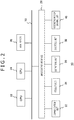
- FIG. 2 depicts a configuration of an internal circuit of the information processing apparatus 10.
- the information processing apparatus 10 includes a central processing unit (CPU) 22, a graphics processing unit (GPU) 24 and a main memory 26.
- the CPU 22 controls processing or signal transmission in or between internal components of the information processing apparatus 10 on the basis of a program such as an operating system or an application.
- the GPU 24 performs image processing.
- the main memory 26 is configured from a random access memory (RAM) and stores programs or data necessary for processing.
- RAM random access memory
- a communication unit 32 configured from a peripheral apparatus interface of universal serial bus (USB), Institute of Electrical and Electronics Engineers (IEEE)1394 or the like or a network interface for a wire or wireless local area network (LAN), a storage unit 34 such as a hard disk drive or a nonvolatile memory, an outputting unit 36 for outputting data to an outputting apparatus such as the display apparatus 16 or a speaker, an inputting unit 38 for inputting data from the image pickup apparatus 12 or the inputting apparatus 14, and a recording medium driving unit 40 for driving a removable recording medium such as a magnetic disk, an optical disc or a semiconductor memory.
- USB universal serial bus
- IEEE Institute of Electrical and Electronics Engineers 1394 or the like or a network interface for a wire or wireless local area network
- LAN local area network
- a storage unit 34 such as a hard disk drive or a nonvolatile memory
- an outputting unit 36 for outputting data to an outputting apparatus such as the display apparatus 16 or a speaker
- an inputting unit 38 for inputting data
- the CPU 22 executes the operating system stored in the storage unit 34 to control the entire information processing apparatus 10.
- the CPU 22 further executes various programs read out from a removable recording medium and loaded into the main memory 26 or downloaded through the communication unit 32.
- the GPU 24 has a function of a geometry engine and a function of a rendering processor, and performs a rendering process in accordance with a rendering instruction from the CPU 22 and stores a resulting display image into a frame buffer not depicted. Then, the GPU 24 converts the display image stored in the frame buffer into a video signal and outputs the video signal to the outputting unit 36.
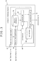
- FIG. 3 depicts a configuration of functional blocks of the information processing apparatus 10.
- the functional blocks depicted in FIG. 3 and FIG. 4 hereinafter described can be configured, in hardware, from such a CPU, a GPU, a main memory, an outputting unit, an inputting unit, a microcomputer, various arithmetic operation units, a buffer memory and so forth as depicted in FIG. 2 , and is implemented, in software, from a computer program or the like loaded from a hard disk or a recording medium into the main memory. Accordingly, it is recognized by those skilled in the art that the functional blocks described above can be implemented in various forms from only hardware, from only software or from a combination of hardware and software and are not limited to any of them.
- the information processing apparatus 10 includes an input information acquisition unit 52 that acquires information relating to a user operation accepted by the inputting apparatus 14, a picked up image acquisition unit 54 that acquires data of a picked up image from the image pickup apparatus 12, a detection unit 60 that performs detection of a block, a recognition unit 62 that recognizes a detected block, an output data production unit 70 that produces output data in response to a position or a movement of the block, an image data storage unit 72 that stores image data to be used in processing such as the picked up image or a depth image, and a block database 64 that stores basic information of the block.
- the information processing apparatus 10 may further include a function block according to contents of information processing performed utilizing a state of a block suitably such as a function block that controls a driving mechanism in the inside of the block.
- the input information acquisition unit 52 notifies the picked up image acquisition unit 54 and the output data production unit 70 of contents of an operation performed by the user through the inputting apparatus 14. This operation includes starting and ending requests of information processing of a game or the like, command inputting during a process and so forth.
- the starting/ending request of a process is notified of also to the image pickup apparatus 12 through the picked up image acquisition unit 54 to control starting/ending of moving image pickup by the image pickup apparatus 12.
- the picked up image acquisition unit 54 acquires frame data of a moving image obtained as a result of image pickup at a predetermined frame rate.
- the predetermined rate here may be a frame rate of a moving image to be picked up by the image pickup apparatus 12 or may be a rate lower than the frame rate.
- the picked up image acquisition unit 54 stores acquired data of a picked up image into the image data storage unit 72.
- the detection unit 60 reads out data of a picked up image from the image data storage unit 72 and detects or chase a block on the play field 100 on the basis of a picture on the image. For example, the detection unit 60 recognizes that a block is placed on the basis of the difference between a picked up image in a state in which a block is not placed and frame images in a moving image being picked up. If it is assumed that the color of the play field 100 is known, then also it is possible to detect a picture having a different color from the known color as a block. After a block is detected once, a movement of the block can be chased by comparison with a preceding frame image. Various technologies have been proposed for chasing a movement of an object in an image, and any of the technologies may be adopted in the present embodiment.
- the image pickup apparatus 12 may be configured from a stereo camera such that a block is detected from depth information from the cameras in an image pickup space.
- a block is detected from depth information from the cameras in an image pickup space.
- depth information of image pickup objects obtained by the stereo camera the position or the height of the image pickup objects in a three-dimensional space having a bottom face given by the play field 100 by coordinate transformation. Then, if an object whose height from the plane of the play field 100 exceeds a predetermined threshold value exists, then this is detected as a block.
- a technique for acquiring depth information of an image pickup object using a stereo camera is widely known.
- the play field 100 defines the bottom of the three-dimensional space of a detection target and can determine a block entering the space above the bottom of the three-dimensional space as a detection target irrespective of whether or not the block is placed on the play field 100.
- the detection unit 60 If a block is detected, then the detection unit 60 notifies the recognition unit 62 of this together with position information of the picture of the block on the image. Further, the detection unit 60 successively supplies results of the chase of the detected block, namely, position information in each frame, to the output data production unit 70 until the block goes out of the play field 100.
- the recognition unit 62 acquires characteristics of an appearance of the block existing at the position notified of from the detection unit 60 using the picked up image read out from the image data storage unit 72.
- the recognition unit 62 compares the appearance characteristic of the block with characteristics of blocks stored in advance in the block database 64 to specify to which block the picture detected in the image belongs.
- the block database 64 information that associates identification numbers of blocks, characteristics in appearance such as a color or a shape, data to be outputted in response to the position or the movement of a block and so forth with each other is stored in advance.
- the recognition unit 62 notifies the output data production unit 70 of an identification number of the block obtained in such a manner as described above and the position information of the block in the image in an associated relationship with each other.
- the output data production unit 70 produces data of an image to be outputted in response to the position and the movement of the block and outputs the data to the display apparatus 16. Therefore, the output data production unit 70 continues to acquire position information of the block from the detection unit 60 and refers to the block database 64 on the basis of the identification number of the block notified of from the recognition unit 62 to determine a process to be performed. For example, the output data production unit 70 renders an object associated with the block at the position of the block on the picked up image or performs processing for the picked up image in response to a positional relationship of the block to a different block.
- the output data production unit 70 reads out the picked up image from the image data storage unit 72 and carries out a corresponding process.
- particular contents of the information processing are not limited as described above, and the information processing may not necessarily use the picked up image. Further, the output data production unit 70 may produce not only data of an image but also audio data of effective sound or the like.
- the block database 64 a program that defines a process to be performed in response to data or a movement of an image to be rendered at the position of the block in the picked up image and so forth are stored in an associated relationship with an identification number of the block.
- a block placed on the play field 100 is recognized on the basis of a picked up image by the image pickup apparatus 12 and performs corresponding information processing.
- color information is significant together with a shape and a size of the block.
- a block sometimes changes in color of a picture on a picked up image from various factors such as an illumination environment in a real space or presence or absence or a color of an article existing around the block. Consequently, the block is sometimes recognized as a different block or a plurality of blocks having similar colors create confusion, and as a result, it is considered that information processing is not performed appropriately. Therefore, in the present embodiment, the calibration chart 102 is provided on the play mat 18 such that adjustment or correction of an image pickup condition or obtained image data is performed in order to improve the recognition accuracy of a block.
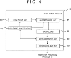
- FIG. 4 depicts a configuration of function blocks of the image pickup apparatus 12.
- the image pickup apparatus 12 includes an image pickup unit 80, a gain processing unit 84, an adjustment processing unit 86, a demosaic unit 88, a gamma correction unit 90 and a data sending out unit 92.
- the function blocks other than the data sending out unit 92 are provided for each of cameras of the stereo camera.
- the image pickup unit 80 is configured from an image pickup element such as a CCD element or a CMOS element and outputs an exposure result at a predetermined timing (for example, 60 times/second) as pixel values of images.
- the image outputted here is a RAW image (non-processed image) configured from one of red, green and blue (RGB) colors and is outputted in a predetermined pixel order such as a raster order to the gain processing unit 84.
- RGB red, green and blue
- the gain processing unit 84 is configured from a variable gain amplification circuit or the like, and amplifies a red primary color signal (R value), a green primary color signal (G value) and a blue primary color signal (B value) outputted from the image pickup unit 80 with set gain values and then outputs resulting signals in a raster order or the like to the demosaic unit 88.
- the adjustment processing unit 86 determines, on the basis of a picture of the calibration chart 102 on the picked up image, at least one of an exposure time period of the image pickup unit 80, a gain value to be set to the gain processing unit 84 and a correction rule for pixel values in the gamma correction unit 90. As hereinafter described, they may be determined on the basis not only of the calibration chart 102 but also of an actual picture of the block. Results of the determination are each notified of to the image pickup unit 80, gain processing unit 84 and gamma correction unit 90.
- the demosaic unit 88 acquires data of RAW images whose pixel values are amplified from the gain processing unit 84 and executes a demosaic (de-mosaic) process of complementing color information to the pixels on the basis of their peripheral pixels to create a full color image.
- a well-known technology can be applied. For example, for a pixel having only a G value in the RAW images, RGB values are determined such that, as an R value, an average of R values of pixels neighboring on the left and the right is used; as a G value, the G value of the pixel is used as it is; and as a B value, a B value of a pixel neighboring upwardly or downwardly is used.
- RGB values are determined such that, as an R value, an average of R values of pixels neighboring on the left and the right is used; as a G value, the G value of the pixel is used as it is; and as a B value, a B value of a pixel neighboring upwardly or downwardly is used
- the gamma correction unit 90 corrects a full color image produced in such a manner as described above with a predetermined correction formula to produce data of an output image.
- the gamma correction unit 90 is basically configured so as to convert a pixel value in accordance with a well-known gamma curve such that color signals output by the image pickup elements are displayed in an appropriate color balance on a display apparatus.
- an image corrected in accordance with a curve obtained by deforming a gamma curve is used such that similar colors can be distinguished from each other with a high degree of accuracy.
- the gamma correction unit 90 outputs data of a produced output image to the adjustment processing unit 86 and the data sending out unit 92.
- the data sending out unit 92 transmits the data of the output image to the information processing apparatus 10 by general communication means.
- the adjustment processing unit 86 acquires, every time various parameters are adjusted in such an order as hereinafter described, an output image after the adjustment from the gamma correction unit 90 and evaluates the output image to perform further adjustment or to determine to end the adjustment.
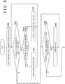
- FIG. 5 is a flow chart illustrating a procedure of information processing including block recognition, which is performed by the image pickup apparatus 12 and the information processing apparatus 10. Operation of this flow chart is started when a user issues a request for starting processing to the information processing apparatus 10 through the inputting apparatus 14. Note that it is assumed that the image pickup apparatus 12 is set by the user such that the entire play mat 18 is included in the field of view.
- the picked up image acquisition unit 54 of the information processing apparatus 10 issues a request to start image pickup to the image pickup apparatus 12, then the image pickup unit 80 of the image pickup apparatus 12 starts image pickup (S10).
- the calibration chart 102 is shown.
- the field of view of the image pickup apparatus 12 may be optimized such that the calibration chart 102 is shown well.
- the information processing apparatus 10 instructs the user to manually perform direction adjustment or magnification adjustment through the display apparatus 16 or the like.
- the information processing apparatus 10 may control the field of view of the image pickup apparatus 12 utilizing a pan-tilter or an electronic zoom not depicted provided in the image pickup apparatus 12.
- the information processing apparatus 10 acquires a picked up image once and detects a region in which a picture of the calibration chart 102 exists in the image.
- the information processing apparatus 10 may notify the image pickup apparatus 12 of a result of the detection such that the image pickup apparatus 12 recognizes the calibration chart 102.
- the adjustment processing unit 86 of the image pickup apparatus 12 adjusts at least one of an exposure time period by the image pickup unit 80, a gain value to be set to the gain processing unit 84 and a correction rule for the gamma correction unit 90 (S12).
- the data sending out unit 92 of the image pickup apparatus 12 outputs data of the output image after the adjustment to the information processing apparatus 10.
- the detection unit 60 of the information processing apparatus 10 supervises, on the basis of the picked up image transmitted thereto from the image pickup apparatus 12, whether or not a new block enters the space above the play field 100 (S14).
- the recognition unit 62 acquires color information of the block on the image (S16). Further, the recognition unit 62 specifies a region in which the color continues as a region of the picture of the block and acquires a shape of the region (S18). Then, the recognition unit 62 refers to the block database 64 to specify an identification number assigned to the block and associates the identification number and the picture on the image with each other on basis of the color and the shape of the region (S20). Although the identification number here is assigned upon shipment or the like of the block, this is not limited to a number but may be a name or the like.
- such a mode may be available that, after the user places the block on the play field 100, the block is registered on the spot by selecting, or designating by voice, a name to be applied to the block or an object to be associated with the block from within a list displayed on the display apparatus 16.
- characteristics of an appearance such as a color of the block, a name designated by the user and so forth are stored in an associated relationship with each other into the block database 64 such that the registration information may be maintained also at a later timing.
- registration information in the past can be specified accurately by preventing the color of the picture of the block from being changed by an external factor.
- a program for a process or the like to be performed in response to image data or a movement of an object may be stored in the block database 64 in an associated relationship with a name or the like that can be designated by the user in place of the block.
- the detection unit 60 chases the picture of the block detected depending upon Y at S14 and continuously notifies the output data production unit 70 of the position information of the picture (S22).
- the output data production unit 70 performs information processing in accordance with the chase result on the basis of the identification number of the block notified of from the recognition unit 62 to produce output data and outputs the output data from the display apparatus 16 or the like (S24). While no block exists in the space above the play field 100 at S14 (N at S14), an initial screen image of a game or the like, the picked up image or the like continues to be displayed (S24). While the user does not request to end the process through the inputting apparatus 14 (N at S26), if a new block enters the space above the play field 100 (Y at S14), then the picture and the identification number of the block are associated with each other and the picture is added as a chase target (S16 to S22).
- the picked up image used in detection and recognition of a block at S14 to S20 is an image whose various parameters have been adjusted by the adjustment processing unit 86 of the image pickup apparatus 12 in order to recognize the block accurately.
- an image for which at least part of such adjustment has not been performed may be used.
- the image pickup apparatus 12 may transmit both of data of an image for which adjustment is performed and another image for which no adjustment is performed to the information processing apparatus 10 as occasion demands.
- both data are transmitted at the same time and are selectively used in the inside of the information processing apparatus 10.
- an adjusted picked up image is transmitted in an initial process, and changeover is performed such that, upon later operation, a picked up image that is not adjusted as yet is transmitted.
- the information processing apparatus 10 notifies the image pickup apparatus 12 of a timing of the changeover.
- adjustment of various parameters in the image pickup apparatus is performed only at S12 using the calibration chart 102.
- at least part of parameters may be adjusted in response to a distribution of colors of blocks that have actually entered the space above the play field 100 or of blocks registered by the user as hereinafter described.
- color information acquired at S16 is notified of from the information processing apparatus 10 to the image pickup apparatus 12 such that the adjustment processing unit 86 of the image pickup apparatus 12 successively records distribution information of the colors of the blocks and performs adjustment as occasion demands.
- FIG. 6 exemplifies a top plan view of the play mat 18.
- the play mat 18 includes a play field 100 indicating a region in which a user places or moves a block, and a calibration chart 102 for optimizing an image pickup condition or adjustment and correction conditions of the image.
- the play field 100 preferably is a region filled with a color different from that of a block such that only the picture of the block can be extracted with high accuracy on the image.
- the present embodiment is not the gist that the present embodiment is limited to this, and a pattern, a sketch or the like may be drawn in the play field 100.
- the shape of the play field 100 is not limited to that depicted in FIG. 6 .
- the calibration chart 102 is configured from a plurality of achromatic color regions of different luminances as depicted in an enlarged scale on the lower side of the play mat 18 in FIG. 6 .
- the calibration chart 102 is configured from four regions of a white region 104, a black region 106, a first grey region 108 and a second grey region 110.
- the disposition or size of the regions is not limited especially.
- the number of grey regions, namely, the number of stages of intermediate luminances is not limited especially.
- a region of a chromatic color may be provided in the calibration chart 102.
- the adjustment processing unit 86 extracts, if it acquires data after gamma correction of an image obtained by image pickup of the calibration chart 102 from the gamma correction unit 90, pictures of the white region 104, black region 106 and first grey region 108 (or second grey region 110) and adjusts the exposure time period and the gain value of each of the regions at least with the following policies.
- the adjustment processing unit 86 compares the luminances of at least two regions from among the white region 104, black region 106, first grey region 108 and second grey region 110 and adjusts a gain value and a correction rule upon gamma correction at least with the following policy.
- FIG. 7 depicts a modification to the calibration chart 102.
- the calibration chart of the present example is configured from a grey step region 112 configured from nine regions of achromatic colors of different luminances from black to white, and a grey region 114 having a predetermined luminance and having a comparatively great area.
- the calibration chart 102 is used to determine an area and a stage number optimum to perform adjustment with high accuracy in response to a color distribution of blocks which can be supposed.
- the policy for adjustment is similar to that described hereinabove.
- FIGS. 8 and 9 are flow charts illustrating a processing procedure by the image pickup apparatus 12 for adjusting the exposure time period, gain value and correction rule upon gamma correction at S12 of FIG. 5 .
- RAW images acquired by the image pickup unit 80 and including a picture of the calibration chart 102 as described hereinabove become an output image through processes by the gain processing unit 84, demosaic unit 88 and gamma correction unit 90.
- the gamma correction unit 90 supplies data of the image to the adjustment processing unit 86. Note that it is assumed that, although omitted in the depicted flow charts, the processes are carried out in parallel to each other at a predetermined rate and, as a result, data of a produced image is used for adjustment by the adjustment processing unit 86 at an appropriate timing. Further, some of the illustrated adjustments may be omitted or changed in order.
- the adjustment processing unit 86 first performs initial adjustment of the white balance using the first grey region 108 in a picked up image at an initial stage supplied from the gamma correction unit 90 (S30).
- average values R_ave, G_ave and B_ave of R values, G values and B values of a picture of the first grey region 108 are each calculated, and gain values Gain_R, Gain_G and Gain_B for the R values, G values and B values are determined in the following manner.
- Gain_R G_ave/R_ave
- Gain_G 1
- Gain_B G_ave/B_ave
- the gain processing unit 84 multiplies the R values, G values and B values of the RAW images by the gain values by to obtain a picture of an achromatic color in which average luminances of the color components of the first grey region 108 are equal to each other, and as a result, the white balance is adjusted.
- the adjustment processing unit 86 sets the determined gain values to the gain processing unit 84, it acquires a picked up image after the adjustment from the gamma correction unit 90 and confirms whether the luminance of the picture of the second grey region 110 from within the picked up image after the adjustment is equal to a target value (S32).
- the target value may be a single value or may have some range.
- the exposure time period is adjusted first, and part that cannot be adjusted with the exposure time period is adjusted with the gain value. This is because, especially where it is necessary to increase the luminance, also noise is amplified as the gain value increases.
- the exposure time period in the image pickup unit 80 is adjusted (Y at S34 and S36).
- the exposure time period is shortened, but if the luminance is lower than the target value, then the exposure time period is increased.
- the gain value to be set to the gain processing unit 84 is adjusted (S38).
- the variation range of the exposure time period is a range within which an appropriate image is obtained taking the scanning speed, frame rate or the like of pixels into consideration.
- the exposure time period is adjusted but also where the gain value is adjusted, it is confirmed whether the luminance of the second grey region 110 is equal to the target value on the basis of a picked up image obtained after the adjustment by the predetermined variation amount (S32). If the luminance of the second grey region 110 is not equal to the target value, then the exposure time period or the gain value is adjusted again (S34 and S36 or S38). This is repeated until after the luminance of the second grey region becomes equal to the target value, and if the target value is reached (Y at S32), then the picked up image at the setting is acquired and it is confirmed whether the luminance of the picture of the white region 104 in the picked up image is equal to or lower than a predetermined value (S40).
- the white color is saturated to decide whether or not the adjustment based on the second grey region at S32 to S38 is appropriate. For example, if it is assumed that the luminance is indicated by 256 gradations, then it is confirmed whether the luminance of the white region 104 is equal to or lower than 250. If the luminance is higher than the predetermined value (N at S40), then the gain value of the luminance set by the processes till then is reduced by multiplying the gain value by a coefficient lower than 1 (S42).
- the adjustment process beginning with S32 adjusts the luminance in only one direction such as a direction in which the luminance is gradually increased from a low luminance or in another direction in which the luminance is gradually decreased from a high luminance, then either it is confirmed from the picture of the white region 104 whether the gain value is excessively high or it is confirmed from the picture of the black region 106 whether the gain value is excessively low.
- the adjustment processing unit 86 acquires picked up images according to the settings performed till then as depicted in FIG. 9 , determines average values in luminance of the pictures of the first grey region 108 and the second grey region 110 and confirms whether the difference between the average values reaches a target value (S44). For example, if it is intended to set the difference in luminance between the first grey region 108 and the second grey region 110 to 10% of the maximum gradation, a difference in luminance of 25 gradations among 256 gradations is required.
- the value for which 10% is exemplified here may be a value that reflects a luminance difference between original colors of the first grey region 108 and the second grey region 110 or may be set to a luminance difference which can be obtained on the image even if the original colors do not have such a difference as described above. For example, if it is intended to handle blocks having colors of luminances close to each other at the same time, then confusion of the blocks can be prevented by increasing the difference in luminance between pictures from that between the original colors. If the luminance difference between the pictures of the first grey region 108 and the second grey region 110 does not reach the target value (N at S44), then the correction rule in the gamma correction unit 90 is adjusted such that the luminance difference reaches the target value (S46).
- a corresponding portion of the original gamma curve is deformed.
- a different correction formula may be inserted into the portion in place of deforming a line as a graph.
- a plurality of tables that discretely represent corresponding relationships between the input luminance and the output luminance may be prepared such that they are selectively utilized.
- end points of the pertaining portion may be gradually moved such that the portion is interpolated by a linear line or a curved line such that the original gamma curve connects to the portion.
- the processes at S44 and S46 are repeated until after the luminance difference between the pictures of the first grey region 108 and the second grey region 110 reaches the target value, and if the target value is reached (Y at S44), then the adjustment processing unit 86 acquires the picked up images at the settings performed till then and adjusts the white balance in each of a plurality of regions that configure the calibration chart 102 from within the picked up images (S48).
- This process is basically similar to that at S30, and gain values Gain_R, Gain_G and Gain_B for the R values, G values and B values in the regions are determined using the formula given hereinabove.
- gain values Gain_R, Gain_G and Gain_B for the R values, G values and B values in the regions are determined using the formula given hereinabove.
- a final gain value is set by averaging for each color component.
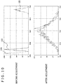
- FIG. 10 is a view illustrating white balance adjustment performed at S30 of FIG. 8 or S48 of FIG. 9 .
- the upper side in FIG. 10 indicates a color histogram and the lower side in FIG. 10 indicates a color histogram of pictures of the same grey region before adjustment and after adjustment, respectively, and the axis of abscissa indicates the pixel value and the axis of ordinate indicates the pixel number.
- a histogram 120 for green components, a histogram 122 for blue components and histogram 124 for red components represent distributions different from each other.
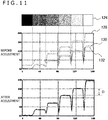
- FIG. 11 illustrates a variation of a pixel value when the white balance is adjusted for a plurality of regions that configure a calibration chart at S48 of FIG. 9 .
- the calibration chart in this case is configured such that, as depicted at an upper stage (calibration chart 126) in FIG. 11 , six regions in which achromatic colors from black to white are represented by six stages of luminance are juxtaposed in a horizontal direction.
- the middle stage and the lower stage represent, where the axis of abscissa indicates the position and the axis of ordinate indicates the pixel value, variations of pixel values of color components when such a calibration chart 126 as described above is scanned in a horizontal direction from the black side, and the middle stage indicates the variations before the adjustment and the lower stage indicates the variations after the adjustment.
- a pixel value 128 of a green component, a pixel value 130 of a blue component and a pixel value 132 of a red component indicate values different from each other in all regions. Therefore, by adjusting the white balance in each region to optimize gain values as described above, it is possible to perform adjustment such that the color components have pixel values substantially equal to each other in all regions as illustrated in the graph after the adjustment. It is to be noted that the luminance difference that is adjusted so as to reach a target value at S44 and S46 of FIG. 9 corresponds, in the case of FIG. 11 , to the difference D in pixel value, for example, between two regions.
- FIG. 12 is a view illustrating a process for adjusting the exposure time period and the gain value at S32 to S38 of FIG. 8 .
- the demosaic unit 88 generates YCbCr images from RAW images and uses the Y image (luminance image) among the YCbCr images to perform adjustment for adjusting a luminance value of a picture of the grey region to a target value.
- the luminance Y of each pixel of RGB images obtained by interpolation of the RAW images is calculated in accordance with the following expression.
- Y 0.299 R + 0.587 G + 0.114 B
- the luminance of the picture of the second grey region before the adjustment has such a value as indicated by "Y" at an upper stage at the left side in FIG. 12 .
- a maximum gradation the luminance value can assume is represented by the top side, and the ratio of the actual average value of the luminance to the maximum gradation is indicated by a dotted region.
- the ratios of average values of RGB to the maximum gradation are indicated in a similar form at the lower stage. It is to be noted that, since the picture of the second grey region is of an achromatic color, where the white balance is adjusted, the average values of RGB become values substantially equal to each other. Further, in operation, the RGB values vary depending upon the color of a block.
- the exposure time periods or the gain values when such luminance values are obtained are adopted as they are, in regard to a block of a color having a luminance value higher than that of the second grey region, the possibility that the luminance of the picture may be saturated is high. Further, in the case of a color whose specific component such as the G value is higher than the others as depicted in FIG. 12 , the specific component becomes liable to be saturated, and as a result, the actual color and the color on the image may become different from each other. Therefore, an appropriate target value is provided for the luminance of the second grey region, and the exposure time period and the gain value are adjusted such that such a picture may be obtained as described hereinabove.
- a target value is determined strictly depending upon the original luminance of a grey region of an adjustment target, the determination is performed qualitatively such that the luminance and the RGB values may not be saturated in regard to any color. For example, if the target value is set to 60% of the maximum gradation, then when the R value or the B value is zero, the G value becomes higher than 100% from the expression given hereinabove. In other words, the possibility that, even if luminances are similar to each other, saturation may occur with a greenish color is high. If the target value is set to 50%, then where the R value or the B value is 0, the G value is 86%. However, the possibility that the luminance may be saturated with a color having a higher luminance is high. If the target value is set to 30%, then even if the R value or the B value is 0, the G value becomes 57% and a margin of 43% occurs.
- the target value is set to approximately 30% as indicated at the upper side at the right side in FIG. 12 , and the exposure time period and the gain value are adjusted with the target value. At this time, the exposure time period is adjusted preferentially as described hereinabove, and if the target value is not reached even if the exposure time period reaches the variation limit, then the gain value of each color component is adjusted.
- target values may be provided for RGB values such that the exposure time period and so forth are adjusted on the basis of RGB images. In this case, by adjusting the white balance first, target values to be set for the RGG images can be unified to 30% or the like.
- FIG. 13 is a view illustrating a process for adjusting a correction rule in the gamma correction unit 90 at S44 and S46 of FIG. 9 .
- gamma correction is performed in order to obtain a good color balance on a display unit from output values from image pickup elements.
- a luminance value before correction is an input luminance Y in
- a luminance value after correction is an output luminance Y out
- the gamma correction is executed in accordance with the following expression.
- Y out Y in 1 ⁇
- y is a value determined on the basis of characteristics and so forth of a supposed display unit.
- the correction expression is indicated by a gamma curve 140 of a thin line where the axis of abscissa indicates the input luminance Y in and the axis of ordinate indicates the output luminance Y out .
- the average values in luminance of the pictures of the first grey region 108 and the second grey region 110 are Y1 and Y2, respectively. If the average values Y1 and Y2 are corrected with the gamma curve 140, then the difference D between the output luminances Y out sometimes becomes comparatively small as indicated by blank circles 142a and 142b. Therefore, the difference D is compared with the target value, and if the difference D does not reach the target value, the gamma curve of the correction rule is deformed to expand the difference between the output luminances Y out .
- a new correction curve 146 (thick line) obtained by deforming a portion of the original gamma curve 140 over which the input luminance changes from Y2 to Y1 and a portion in the proximity of the portion of the original gamma curve 140 is generated to expand the difference D' between the output luminances Y out .
- the output value at the blank circle 142a corresponding to the input luminance Y1 is increased to that at a black circle 144a
- the output value at the blank circle 142b corresponding to the input luminance Y2 is decreased to that of a black circle 144b.
- the extent of such increase and decrease may be a fixed value or may be varied in response to the input luminance.
- the correction curve 146 is obtained by such interpolation by a general technique that the correction curve 146 passes the black circles 144a and 144b and connects to the original gamma curve 140. It is to be noted that the correction curve 146 is not limited to a curved line but may partly or entirely be a linear line.
- distinction in color between blocks having the luminances of the first grey region 108 and the second grey region 110 can be recognized with high accuracy. That distinction in color can be recognized with high accuracy signifies that, even if the luminance of blocks originally having colors same as each other disperses from some external factor, the colors can be regarded as the same color. As a result, block recognition based on a color can be improved in accuracy.
- the luminance of the first grey region 108 and the second grey region 110 is desirable to determine the luminance of the first grey region 108 and the second grey region 110 on the basis of a luminance distribution of colors of blocks used in operation. For example, where it is supposed to use two blocks of different colors having luminances close to each other, if the luminances of the first grey region 108 and the second grey region 110 are adjusted to the luminances of the two colors and then adjustment of the correction curve is performed in such a manner as depicted in FIG. 13 , then the difference between the output values of the luminances of the pictures of them can be emphasized.
- FIG. 14 is a view illustrating a technique for adjusting a correction curve on the basis of a color distribution of blocks.
- the upper stage indicates a histogram that represents, for each luminance of a color of a block, a detection frequency of the block detected when a user places, in operation, the block into the space above the play field 100.
- the distribution is updated in response to a situation in operation.
- the adjustment processing unit 86 of the image pickup apparatus 12 cumulatively records such information to produce and update such a histogram as depicted in FIG. 14 . Then, the correction curve is adjusted as occasion demands on the basis of the histogram.
- blocks of colors one-sided to a luminance zone A and another luminance zone B are used. Since colors belonging to each luminance zone have similar luminances, the possibility that they may be confused in operation is high. Therefore, a gamma curve is adjusted similarly as in the case illustrated in FIG. 13 such that a sufficient difference may appear between the output luminances.
- a difference D A in output luminance when the lowest luminance Amin and the highest luminance Amax of the luminance zone A are corrected with the gamma curve and a difference D B in output luminance when the lowest luminance Bmin and the highest luminance Bmax of the luminance zone B are corrected with the gamma curve are confirmed, and if the differences D A and D B do not reach the respective target values, then the curve is deformed so as to expand the differences.
- the difference D A in output luminance of the luminance zone A reaches the target value
- the difference D B in output luminance of the luminance zone B does not reach the target value, and such a correction curve as indicated by a thick line is produced so as to expand the difference D B to D B '. Consequently, the possibility that colors belonging to the luminance zone B may be confused is suppressed and all blocks can be recognized with high accuracy. It is to be noted that, since a frequency equal to or higher than 1 is obtained in the luminance zone B at three luminance steps, such adjustment may be performed which increases differences among three points including an intermediate luminance in addition to the lowest luminance Bmin and the highest luminance Bmax.
- the target value to be provided to the difference in output luminance may be changed in response to the frequency.
- the target value for the luminance zone B since the frequency of the luminance zone B is high in comparison with the luminance zone A, the target value for the luminance zone B may be set to a higher value.
- Similar adjustment can be performed even if the luminance of a grey region of the calibration chart 102 is adjusted to the luminance of the color of a block supposed to be used instead of the user to adjust a correction curve on the basis of a picture of a block actually entered on the play field 100.
- such luminance distributions of blocks as depicted in FIG. 14 are acquired in advance, and four grey regions having the lowest luminance Amin and the highest luminance Amax of the luminance zone A and the lowest luminance Bmin and the highest luminance Bmax of the luminance zone B are prepared in the calibration chart 102.
- the grey region to be used for adjustment is recorded in advance on the basis of colors of blocks detected in the past or colors of blocks to be supplied in a set.
- Part of the calibration chart 102 may be configured from a color chart of chromatic colors confirming to colors of blocks.
- the variable that is the luminance in FIG. 14 is a three-dimensional or two-dimensional variable such as (R, G, B) or (R/G, B/G).
- a color region in which colors of blocks are dense in comparison with a predetermined reference density in the color space is detected, and if a standard deviation after correction of the colors or a distance between colors in the color space does not reach a target value, then the gamma curve is deformed so as to expand the standard deviation or the distance.
- FIG. 15 is a view illustrating a technique for adjusting the gain values of RGB utilizing the color chart. This process is performed, for example, in the flow chart of FIG. 8 , after the processes at S32 to S42 by which the exposure time period or the gain value is adjusted on the basis of a luminance of a picture of a grey region of the calibration chart 102.
- a first color, a second color and a third color similar to each other are available.
- the left side in FIG. 15 is a color histogram of each color, which is represented in a form similar to that of FIG. 10 .
- the adjustment processing unit 86 extracts a picture of the second color region in a picked up image of the calibration chart 102 and adjusts the white balance with the picture.
- the gain values of the color components are determined such that the second color becomes an achromatic color.
- the manner of adjustment of the white balance is similar to that described hereinabove with reference to FIG. 10 . Consequently, distributions of the color components become substantially equal to each other as in a color histogram of the second color at the right side in FIG. 15 .
- the histograms of the first color and the third color become such as those depicted at the right side.
- this color information is different from the original colors of the first color, second color and third color, a difference among the first to third colors appears clearly.
- the first to third colors are all greenish colors having high G values
- the first color is a strongly bluish color
- the second color is close to an achromatic color while the third color is a strongly reddish color.
- FIG. 16 depicts a modification to the play mat in the present embodiment.
- a play mat 150 of the present example is configured such that a play field 152 is provided over a substantially overall area and a calibration chart 154 is prepared separately. Further, when an image pickup condition or a correction condition of an image is to be adjusted using the calibration chart 154, the calibration chart 154 is placed on and used together with the play field 152. The calibration chart 154 may be stuck by a hook and loop fastener or the like. On the other hand, in operation where a block is used, the calibration chart 154 is removed to expose the play field 152.
- both of the play field 152 and the calibration chart 154 can be configured so as to have an area equal to that of the play mat 150.
- a greater number of regions of different luminances or colors can be prepared as the calibration chart 154, and blocks can be handled at a place of a greater area.
- the play mat may be configured such that a calibration chart is indicated over a substantially overall area of the rear face of the play mat 150. In this case, if the user turns over the play mat as occasion demands, then an effect similar to that described hereinabove can be achieved.
- a calibration chart including a plurality of regions of different luminances or colors is provided on a play mat that defines a target space from which a block is to be detected. Then, as an initial process in an image pickup apparatus, at least one of an exposure time period, a gain value to be provided to each color component and a correction rule upon gamma correction is adjusted on the basis of a picture of the calibration chart in a picked up image.
- the exposure time period and the gain value to be provided to each color component are adjusted on the basis of the luminance of a picture of a grey region such that a gradation number can be utilized utmost within a range within which the value of a luminance or a color component is not saturated with any color.
- the white balance is adjusted on the basis of a region of an achromatic color.
- a correction curve upon gamma correction is adjusted such that an output luminance difference between regions of different luminances may appear sufficiently.
- a correction curve upon gamma correction may be adjusted in response to a color distribution or a luminance distribution of a block actually entering a space above a play field such that the difference in luminance or color in an output image is emphasized. From those, color information of a block can be acquired from a picked up image in a state in which the influence of a variation of the image pickup environment such as illumination or presence or absence of a different article. Further, confusion between blocks having similar colors can be avoided. As a result, the recognition accuracy of a block based on a color can be improved.
- Information processing system 20a Block, 10 Information processing apparatus, 12 Image pickup apparatus, 14 Inputting apparatus, 16 Display apparatus, 18 Play mat, 22 CPU, 24 GPU, 26 Main memory, 52 Input information acquisition unit, 54 Picked up image acquisition unit, 60 Detection unit, 62 Recognition unit, 64 Block database, 70 Output data production unit, 72 Image data storage unit, 80 Image pickup unit, 84 Gain processing unit, 86 Adjustment processing unit, 88 Demosaic unit, 90 Gamma correction unit, 92 Data sending out unit, 100 Play field, 102 Calibration chart, 150 Play mat, 152 Play field, 154 Calibration chart.
- the present invention can be utilized in toys, learning equipment, computers, game apparatus, and information processing apparatus, and systems including them.
Landscapes
- Engineering & Computer Science (AREA)
- Multimedia (AREA)
- Signal Processing (AREA)
- Physics & Mathematics (AREA)
- General Physics & Mathematics (AREA)
- Theoretical Computer Science (AREA)
- General Health & Medical Sciences (AREA)
- Biomedical Technology (AREA)
- Health & Medical Sciences (AREA)
- Human Computer Interaction (AREA)
- Image Processing (AREA)
- Image Analysis (AREA)
- Studio Devices (AREA)
- Color Television Image Signal Generators (AREA)
Applications Claiming Priority (2)
| Application Number | Priority Date | Filing Date | Title |
|---|---|---|---|
| JP2015022243A JP6345612B2 (ja) | 2015-02-06 | 2015-02-06 | 撮像装置、情報処理システム、マット、および画像生成方法 |
| PCT/JP2016/052777 WO2016125714A1 (ja) | 2015-02-06 | 2016-01-29 | 撮像装置、情報処理システム、マット、および画像生成方法 |
Publications (3)
| Publication Number | Publication Date |
|---|---|
| EP3255885A1 true EP3255885A1 (de) | 2017-12-13 |
| EP3255885A4 EP3255885A4 (de) | 2018-09-12 |
| EP3255885B1 EP3255885B1 (de) | 2020-03-25 |
Family
ID=56564060
Family Applications (1)
| Application Number | Title | Priority Date | Filing Date |
|---|---|---|---|
| EP16746545.9A Active EP3255885B1 (de) | 2015-02-06 | 2016-01-29 | Bildgebungsvorrichtung, informationsverarbeitungssystem, bilderzeugungsverfahren und entsprechendes computerprogramm |
Country Status (4)
| Country | Link |
|---|---|
| US (2) | US10477175B2 (de) |
| EP (1) | EP3255885B1 (de) |
| JP (1) | JP6345612B2 (de) |
| WO (1) | WO2016125714A1 (de) |
Families Citing this family (18)
| Publication number | Priority date | Publication date | Assignee | Title |
|---|---|---|---|---|
| US10235587B2 (en) * | 2014-03-04 | 2019-03-19 | Samsung Electronics Co., Ltd. | Method and system for optimizing an image capturing boundary in a proposed image |
| JP6345612B2 (ja) * | 2015-02-06 | 2018-06-20 | 株式会社ソニー・インタラクティブエンタテインメント | 撮像装置、情報処理システム、マット、および画像生成方法 |
| WO2017149932A1 (ja) * | 2016-03-03 | 2017-09-08 | ソニー株式会社 | 医療用画像処理装置、システム、方法及びプログラム |
| WO2018142228A2 (en) | 2017-01-19 | 2018-08-09 | Mindmaze Holding Sa | Systems, methods, apparatuses and devices for detecting facial expression and for tracking movement and location including for at least one of a virtual and augmented reality system |
| US10943100B2 (en) | 2017-01-19 | 2021-03-09 | Mindmaze Holding Sa | Systems, methods, devices and apparatuses for detecting facial expression |
| CN110892408A (zh) * | 2017-02-07 | 2020-03-17 | 迈恩德玛泽控股股份有限公司 | 用于立体视觉和跟踪的系统、方法和装置 |
| US10373341B2 (en) * | 2017-08-28 | 2019-08-06 | Facebook, Inc. | Systems and methods for automated color correction |
| US11328533B1 (en) | 2018-01-09 | 2022-05-10 | Mindmaze Holding Sa | System, method and apparatus for detecting facial expression for motion capture |
| JP7151234B2 (ja) * | 2018-07-19 | 2022-10-12 | 株式会社デンソー | カメラシステムおよびイベント記録システム |
| US10964262B1 (en) * | 2018-08-30 | 2021-03-30 | Apple Inc. | Systems and methods for reducing visual artifacts in displays due to refresh rate |
| JP7007324B2 (ja) * | 2019-04-25 | 2022-01-24 | ファナック株式会社 | 画像処理装置、画像処理方法、及びロボットシステム |
| US11216981B2 (en) | 2019-07-26 | 2022-01-04 | Cnh Industrial America Llc | System and method for calibrating image data during an agricultural operation using a color indicator |
| CA3160797A1 (en) | 2019-11-13 | 2021-05-20 | Scanwell Health, Inc. | Diagnostic test kits for sample preparation and analysis |
| JP7430554B2 (ja) * | 2020-03-19 | 2024-02-13 | 株式会社キーエンス | 光学式情報読取装置、光学式情報読取方法、光学式情報読取プログラム及びコンピュータで読取可能な記録媒体並びに記録した機器 |
| FR3111451B1 (fr) * | 2020-06-12 | 2022-11-11 | Acep Trylive | Dispositif et procédé pour l’acquisition d’images d’une paire de lunettes |
| EP4214669A1 (de) | 2020-09-17 | 2023-07-26 | Scanwell Health, Inc. | Diagnostische testkits und verfahren zur analyse davon |
| CN116324382B (zh) | 2020-10-23 | 2026-03-10 | 贝克顿·迪金森公司 | 用于测试设备的成像和基于图像的分析的系统和方法 |
| USD970033S1 (en) | 2020-10-23 | 2022-11-15 | Becton, Dickinson And Company | Cartridge imaging background device |
Family Cites Families (13)
| Publication number | Priority date | Publication date | Assignee | Title |
|---|---|---|---|---|
| US5546475A (en) * | 1994-04-29 | 1996-08-13 | International Business Machines Corporation | Produce recognition system |
| JPH1196333A (ja) | 1997-09-16 | 1999-04-09 | Olympus Optical Co Ltd | カラー画像処理装置 |
| US6775633B2 (en) * | 2001-12-31 | 2004-08-10 | Kodak Polychrome Graphics, Llc | Calibration techniques for imaging devices |
| US7639260B2 (en) * | 2004-12-15 | 2009-12-29 | Xerox Corporation | Camera-based system for calibrating color displays |
| AU2007217794A1 (en) * | 2006-02-16 | 2007-08-30 | Clean Earth Technologies, Llc | Method for spectral data classification and detection in diverse lighting conditions |
| JP4331190B2 (ja) * | 2006-09-21 | 2009-09-16 | 株式会社ソニー・コンピュータエンタテインメント | ゲーム装置、ゲーム制御方法、及びゲーム制御プログラム |
| US20100195902A1 (en) * | 2007-07-10 | 2010-08-05 | Ronen Horovitz | System and method for calibration of image colors |
| EP2114065B1 (de) * | 2008-05-02 | 2017-08-23 | Nintendo Co., Ltd. | Farbumwandlungsvorrichtung, Bildgebungsvorrichtung, Speichermedium, das das Farbumwandlungsprogramm speichert und Speichermedium, das das Bildgebungsprogramm speichert |
| EP2462537A1 (de) * | 2009-08-04 | 2012-06-13 | Eyecue Vision Technologies Ltd. | System und verfahren zur objektextraktion |
| GB201000835D0 (en) | 2010-01-19 | 2010-03-03 | Akzo Nobel Coatings Int Bv | Method and system for determining colour from an image |
| US8532371B2 (en) * | 2010-10-04 | 2013-09-10 | Datacolor Holding Ag | Method and apparatus for evaluating color in an image |
| KR20150056980A (ko) * | 2013-11-18 | 2015-05-28 | 삼성전자주식회사 | 멀티 디스플레이의 색편차 보정용 카메라의 제어 방법 및 장치 |
| JP6345612B2 (ja) * | 2015-02-06 | 2018-06-20 | 株式会社ソニー・インタラクティブエンタテインメント | 撮像装置、情報処理システム、マット、および画像生成方法 |
-
2015
- 2015-02-06 JP JP2015022243A patent/JP6345612B2/ja active Active
-
2016
- 2016-01-29 WO PCT/JP2016/052777 patent/WO2016125714A1/ja not_active Ceased
- 2016-01-29 US US15/547,707 patent/US10477175B2/en active Active
- 2016-01-29 EP EP16746545.9A patent/EP3255885B1/de active Active
-
2019
- 2019-10-07 US US16/594,982 patent/US10869010B2/en active Active
Also Published As
| Publication number | Publication date |
|---|---|
| JP2016146536A (ja) | 2016-08-12 |
| US10869010B2 (en) | 2020-12-15 |
| EP3255885B1 (de) | 2020-03-25 |
| US20200045284A1 (en) | 2020-02-06 |
| EP3255885A4 (de) | 2018-09-12 |
| JP6345612B2 (ja) | 2018-06-20 |
| US10477175B2 (en) | 2019-11-12 |
| WO2016125714A1 (ja) | 2016-08-11 |
| US20180027222A1 (en) | 2018-01-25 |
Similar Documents
| Publication | Publication Date | Title |
|---|---|---|
| US10869010B2 (en) | Image pickup apparatus, information processing system, mat, and image generation method | |
| US8446485B2 (en) | Image processing apparatus, image processing method, and storage medium thereof | |
| US9734565B2 (en) | Image processing device and method for correcting an image according to a revised correction value | |
| JP4398713B2 (ja) | 色信号補正装置及びその方法、並びにそれを用いた映像信号処置システム及びその方法 | |
| US8446493B2 (en) | Image processing apparatus, imaging apparatus, computer readable storage medium storing image processing program, and image processing method for performing color processing on a raw image | |
| US20170109864A1 (en) | Image processing apparatus, image processing system, imaging apparatus and image processing method | |
| JP6006543B2 (ja) | 画像処理装置および画像処理方法 | |
| US10281714B2 (en) | Projector and projection system that correct optical characteristics, image processing apparatus, and storage medium | |
| JP2007110576A (ja) | 被写体像データの色補正装置およびその制御方法 | |
| JP2011249939A (ja) | 画像処理装置、制御方法、およびプログラム | |
| CN103037167A (zh) | 成像装置、成像方法和程序 | |
| JP2007215216A (ja) | カラー画像のモノトーン化処理 | |
| JP2014220815A (ja) | 画像色調整方法及びその電子装置 | |
| JP4001079B2 (ja) | カラー画像のモノトーン化処理 | |
| JP2005284292A (ja) | 映像の色補正装置、方法及びその方法をコンピュータに実施させるプログラムを記録する記録媒体 | |
| JP2007124236A (ja) | 画像処理装置、画像処理方法及び画像処理プログラム | |
| US20150085162A1 (en) | Perceptual radiometric compensation system adaptable to a projector-camera system | |
| CN113615148B (zh) | 相机色彩图像处理 | |
| EP3534601B1 (de) | Bildverarbeitungsvorrichtung, bildverarbeitungsverfahren und speichermedium | |
| CN114820822A (zh) | 图像处理方法、装置、电子设备及可读存储介质 | |
| JP2006229616A (ja) | 映像信号処理回路 | |
| JP2007081724A (ja) | 撮像装置及び撮像装置の制御方法 | |
| JP2008219290A (ja) | 信号変換装置、映像表示装置及び信号変換方法 | |
| JP2018207282A (ja) | 表示制御装置、表示装置及び表示制御方法 | |
| JP2023044689A (ja) | 画像処理装置 |
Legal Events
| Date | Code | Title | Description |
|---|---|---|---|
| STAA | Information on the status of an ep patent application or granted ep patent |
Free format text: STATUS: THE INTERNATIONAL PUBLICATION HAS BEEN MADE |
|
| PUAI | Public reference made under article 153(3) epc to a published international application that has entered the european phase |
Free format text: ORIGINAL CODE: 0009012 |
|
| STAA | Information on the status of an ep patent application or granted ep patent |
Free format text: STATUS: REQUEST FOR EXAMINATION WAS MADE |
|
| 17P | Request for examination filed |
Effective date: 20170727 |
|
| AK | Designated contracting states |
Kind code of ref document: A1 Designated state(s): AL AT BE BG CH CY CZ DE DK EE ES FI FR GB GR HR HU IE IS IT LI LT LU LV MC MK MT NL NO PL PT RO RS SE SI SK SM TR |
|
| AX | Request for extension of the european patent |
Extension state: BA ME |
|
| DAV | Request for validation of the european patent (deleted) | ||
| DAX | Request for extension of the european patent (deleted) | ||
| A4 | Supplementary search report drawn up and despatched |
Effective date: 20180813 |
|
| RIC1 | Information provided on ipc code assigned before grant |
Ipc: H04N 9/69 20060101ALI20180807BHEP Ipc: A63F 13/213 20140101ALI20180807BHEP Ipc: G06T 7/90 20170101ALI20180807BHEP Ipc: G06K 9/60 20060101ALI20180807BHEP Ipc: H04N 5/225 20060101ALI20180807BHEP Ipc: G03B 15/00 20060101ALI20180807BHEP Ipc: G06K 9/00 20060101ALI20180807BHEP Ipc: H04N 9/04 20060101AFI20180807BHEP Ipc: H04N 1/407 20060101ALI20180807BHEP Ipc: G06T 7/73 20170101ALI20180807BHEP Ipc: H04N 5/235 20060101ALI20180807BHEP Ipc: G06T 1/00 20060101ALI20180807BHEP Ipc: H04N 9/73 20060101ALI20180807BHEP |
|
| STAA | Information on the status of an ep patent application or granted ep patent |
Free format text: STATUS: EXAMINATION IS IN PROGRESS |
|
| 17Q | First examination report despatched |
Effective date: 20190408 |
|
| GRAP | Despatch of communication of intention to grant a patent |
Free format text: ORIGINAL CODE: EPIDOSNIGR1 |
|
| STAA | Information on the status of an ep patent application or granted ep patent |
Free format text: STATUS: GRANT OF PATENT IS INTENDED |
|
| INTG | Intention to grant announced |
Effective date: 20191104 |
|
| GRAS | Grant fee paid |
Free format text: ORIGINAL CODE: EPIDOSNIGR3 |
|
| GRAA | (expected) grant |
Free format text: ORIGINAL CODE: 0009210 |
|
| STAA | Information on the status of an ep patent application or granted ep patent |
Free format text: STATUS: THE PATENT HAS BEEN GRANTED |
|
| AK | Designated contracting states |
Kind code of ref document: B1 Designated state(s): AL AT BE BG CH CY CZ DE DK EE ES FI FR GB GR HR HU IE IS IT LI LT LU LV MC MK MT NL NO PL PT RO RS SE SI SK SM TR |
|
| REG | Reference to a national code |
Ref country code: GB Ref legal event code: FG4D |
|
| REG | Reference to a national code |
Ref country code: AT Ref legal event code: REF Ref document number: 1249949 Country of ref document: AT Kind code of ref document: T Effective date: 20200415 Ref country code: IE Ref legal event code: FG4D |
|
| REG | Reference to a national code |
Ref country code: DE Ref legal event code: R096 Ref document number: 602016032546 Country of ref document: DE |
|
| PG25 | Lapsed in a contracting state [announced via postgrant information from national office to epo] |
Ref country code: FI Free format text: LAPSE BECAUSE OF FAILURE TO SUBMIT A TRANSLATION OF THE DESCRIPTION OR TO PAY THE FEE WITHIN THE PRESCRIBED TIME-LIMIT Effective date: 20200325 Ref country code: RS Free format text: LAPSE BECAUSE OF FAILURE TO SUBMIT A TRANSLATION OF THE DESCRIPTION OR TO PAY THE FEE WITHIN THE PRESCRIBED TIME-LIMIT Effective date: 20200325 Ref country code: NO Free format text: LAPSE BECAUSE OF FAILURE TO SUBMIT A TRANSLATION OF THE DESCRIPTION OR TO PAY THE FEE WITHIN THE PRESCRIBED TIME-LIMIT Effective date: 20200625 |
|
| PG25 | Lapsed in a contracting state [announced via postgrant information from national office to epo] |
Ref country code: SE Free format text: LAPSE BECAUSE OF FAILURE TO SUBMIT A TRANSLATION OF THE DESCRIPTION OR TO PAY THE FEE WITHIN THE PRESCRIBED TIME-LIMIT Effective date: 20200325 Ref country code: LV Free format text: LAPSE BECAUSE OF FAILURE TO SUBMIT A TRANSLATION OF THE DESCRIPTION OR TO PAY THE FEE WITHIN THE PRESCRIBED TIME-LIMIT Effective date: 20200325 Ref country code: HR Free format text: LAPSE BECAUSE OF FAILURE TO SUBMIT A TRANSLATION OF THE DESCRIPTION OR TO PAY THE FEE WITHIN THE PRESCRIBED TIME-LIMIT Effective date: 20200325 Ref country code: GR Free format text: LAPSE BECAUSE OF FAILURE TO SUBMIT A TRANSLATION OF THE DESCRIPTION OR TO PAY THE FEE WITHIN THE PRESCRIBED TIME-LIMIT Effective date: 20200626 Ref country code: BG Free format text: LAPSE BECAUSE OF FAILURE TO SUBMIT A TRANSLATION OF THE DESCRIPTION OR TO PAY THE FEE WITHIN THE PRESCRIBED TIME-LIMIT Effective date: 20200625 |
|
| REG | Reference to a national code |
Ref country code: NL Ref legal event code: MP Effective date: 20200325 |
|
| REG | Reference to a national code |
Ref country code: LT Ref legal event code: MG4D |
|
| PG25 | Lapsed in a contracting state [announced via postgrant information from national office to epo] |
Ref country code: NL Free format text: LAPSE BECAUSE OF FAILURE TO SUBMIT A TRANSLATION OF THE DESCRIPTION OR TO PAY THE FEE WITHIN THE PRESCRIBED TIME-LIMIT Effective date: 20200325 |
|
| PG25 | Lapsed in a contracting state [announced via postgrant information from national office to epo] |
Ref country code: IS Free format text: LAPSE BECAUSE OF FAILURE TO SUBMIT A TRANSLATION OF THE DESCRIPTION OR TO PAY THE FEE WITHIN THE PRESCRIBED TIME-LIMIT Effective date: 20200725 Ref country code: EE Free format text: LAPSE BECAUSE OF FAILURE TO SUBMIT A TRANSLATION OF THE DESCRIPTION OR TO PAY THE FEE WITHIN THE PRESCRIBED TIME-LIMIT Effective date: 20200325 Ref country code: SM Free format text: LAPSE BECAUSE OF FAILURE TO SUBMIT A TRANSLATION OF THE DESCRIPTION OR TO PAY THE FEE WITHIN THE PRESCRIBED TIME-LIMIT Effective date: 20200325 Ref country code: SK Free format text: LAPSE BECAUSE OF FAILURE TO SUBMIT A TRANSLATION OF THE DESCRIPTION OR TO PAY THE FEE WITHIN THE PRESCRIBED TIME-LIMIT Effective date: 20200325 Ref country code: CZ Free format text: LAPSE BECAUSE OF FAILURE TO SUBMIT A TRANSLATION OF THE DESCRIPTION OR TO PAY THE FEE WITHIN THE PRESCRIBED TIME-LIMIT Effective date: 20200325 Ref country code: RO Free format text: LAPSE BECAUSE OF FAILURE TO SUBMIT A TRANSLATION OF THE DESCRIPTION OR TO PAY THE FEE WITHIN THE PRESCRIBED TIME-LIMIT Effective date: 20200325 Ref country code: LT Free format text: LAPSE BECAUSE OF FAILURE TO SUBMIT A TRANSLATION OF THE DESCRIPTION OR TO PAY THE FEE WITHIN THE PRESCRIBED TIME-LIMIT Effective date: 20200325 Ref country code: PT Free format text: LAPSE BECAUSE OF FAILURE TO SUBMIT A TRANSLATION OF THE DESCRIPTION OR TO PAY THE FEE WITHIN THE PRESCRIBED TIME-LIMIT Effective date: 20200818 |
|
| REG | Reference to a national code |
Ref country code: AT Ref legal event code: MK05 Ref document number: 1249949 Country of ref document: AT Kind code of ref document: T Effective date: 20200325 |
|
| REG | Reference to a national code |
Ref country code: DE Ref legal event code: R097 Ref document number: 602016032546 Country of ref document: DE |
|
| PG25 | Lapsed in a contracting state [announced via postgrant information from national office to epo] |
Ref country code: DK Free format text: LAPSE BECAUSE OF FAILURE TO SUBMIT A TRANSLATION OF THE DESCRIPTION OR TO PAY THE FEE WITHIN THE PRESCRIBED TIME-LIMIT Effective date: 20200325 Ref country code: AT Free format text: LAPSE BECAUSE OF FAILURE TO SUBMIT A TRANSLATION OF THE DESCRIPTION OR TO PAY THE FEE WITHIN THE PRESCRIBED TIME-LIMIT Effective date: 20200325 Ref country code: ES Free format text: LAPSE BECAUSE OF FAILURE TO SUBMIT A TRANSLATION OF THE DESCRIPTION OR TO PAY THE FEE WITHIN THE PRESCRIBED TIME-LIMIT Effective date: 20200325 Ref country code: IT Free format text: LAPSE BECAUSE OF FAILURE TO SUBMIT A TRANSLATION OF THE DESCRIPTION OR TO PAY THE FEE WITHIN THE PRESCRIBED TIME-LIMIT Effective date: 20200325 |
|
| PLBE | No opposition filed within time limit |
Free format text: ORIGINAL CODE: 0009261 |
|
| STAA | Information on the status of an ep patent application or granted ep patent |
Free format text: STATUS: NO OPPOSITION FILED WITHIN TIME LIMIT |
|
| PG25 | Lapsed in a contracting state [announced via postgrant information from national office to epo] |
Ref country code: PL Free format text: LAPSE BECAUSE OF FAILURE TO SUBMIT A TRANSLATION OF THE DESCRIPTION OR TO PAY THE FEE WITHIN THE PRESCRIBED TIME-LIMIT Effective date: 20200325 |
|
| 26N | No opposition filed |
Effective date: 20210112 |
|
| PG25 | Lapsed in a contracting state [announced via postgrant information from national office to epo] |
Ref country code: SI Free format text: LAPSE BECAUSE OF FAILURE TO SUBMIT A TRANSLATION OF THE DESCRIPTION OR TO PAY THE FEE WITHIN THE PRESCRIBED TIME-LIMIT Effective date: 20200325 |
|
| PG25 | Lapsed in a contracting state [announced via postgrant information from national office to epo] |
Ref country code: MC Free format text: LAPSE BECAUSE OF FAILURE TO SUBMIT A TRANSLATION OF THE DESCRIPTION OR TO PAY THE FEE WITHIN THE PRESCRIBED TIME-LIMIT Effective date: 20200325 |
|
| REG | Reference to a national code |
Ref country code: CH Ref legal event code: PL |
|
| PG25 | Lapsed in a contracting state [announced via postgrant information from national office to epo] |
Ref country code: LU Free format text: LAPSE BECAUSE OF NON-PAYMENT OF DUE FEES Effective date: 20210129 |
|
| REG | Reference to a national code |
Ref country code: BE Ref legal event code: MM Effective date: 20210131 |
|
| PG25 | Lapsed in a contracting state [announced via postgrant information from national office to epo] |
Ref country code: LI Free format text: LAPSE BECAUSE OF NON-PAYMENT OF DUE FEES Effective date: 20210131 Ref country code: CH Free format text: LAPSE BECAUSE OF NON-PAYMENT OF DUE FEES Effective date: 20210131 |
|
| PG25 | Lapsed in a contracting state [announced via postgrant information from national office to epo] |
Ref country code: IE Free format text: LAPSE BECAUSE OF NON-PAYMENT OF DUE FEES Effective date: 20210129 |
|
| PG25 | Lapsed in a contracting state [announced via postgrant information from national office to epo] |
Ref country code: BE Free format text: LAPSE BECAUSE OF NON-PAYMENT OF DUE FEES Effective date: 20210131 |
|
| REG | Reference to a national code |
Ref country code: DE Ref legal event code: R079 Ref document number: 602016032546 Country of ref document: DE Free format text: PREVIOUS MAIN CLASS: H04N0009040000 Ipc: H04N0023100000 |
|
| P01 | Opt-out of the competence of the unified patent court (upc) registered |
Effective date: 20230519 |
|
| PG25 | Lapsed in a contracting state [announced via postgrant information from national office to epo] |
Ref country code: CY Free format text: LAPSE BECAUSE OF FAILURE TO SUBMIT A TRANSLATION OF THE DESCRIPTION OR TO PAY THE FEE WITHIN THE PRESCRIBED TIME-LIMIT Effective date: 20200325 |
|
| P02 | Opt-out of the competence of the unified patent court (upc) changed |
Effective date: 20230528 |
|
| PG25 | Lapsed in a contracting state [announced via postgrant information from national office to epo] |
Ref country code: HU Free format text: LAPSE BECAUSE OF FAILURE TO SUBMIT A TRANSLATION OF THE DESCRIPTION OR TO PAY THE FEE WITHIN THE PRESCRIBED TIME-LIMIT; INVALID AB INITIO Effective date: 20160129 |
|
| PG25 | Lapsed in a contracting state [announced via postgrant information from national office to epo] |
Ref country code: MK Free format text: LAPSE BECAUSE OF FAILURE TO SUBMIT A TRANSLATION OF THE DESCRIPTION OR TO PAY THE FEE WITHIN THE PRESCRIBED TIME-LIMIT Effective date: 20200325 |
|
| PG25 | Lapsed in a contracting state [announced via postgrant information from national office to epo] |
Ref country code: MT Free format text: LAPSE BECAUSE OF FAILURE TO SUBMIT A TRANSLATION OF THE DESCRIPTION OR TO PAY THE FEE WITHIN THE PRESCRIBED TIME-LIMIT Effective date: 20200325 |
|
| PG25 | Lapsed in a contracting state [announced via postgrant information from national office to epo] |
Ref country code: TR Free format text: LAPSE BECAUSE OF FAILURE TO SUBMIT A TRANSLATION OF THE DESCRIPTION OR TO PAY THE FEE WITHIN THE PRESCRIBED TIME-LIMIT Effective date: 20200325 |
|
| PGFP | Annual fee paid to national office [announced via postgrant information from national office to epo] |
Ref country code: GB Payment date: 20251220 Year of fee payment: 11 |
|
| PGFP | Annual fee paid to national office [announced via postgrant information from national office to epo] |
Ref country code: FR Payment date: 20251217 Year of fee payment: 11 |
|
| PGFP | Annual fee paid to national office [announced via postgrant information from national office to epo] |
Ref country code: DE Payment date: 20251217 Year of fee payment: 11 |