EP3255960B1 - Générateur d'anions comprenant une source de plasma comprenant un diélectrique poreux - Google Patents
Générateur d'anions comprenant une source de plasma comprenant un diélectrique poreux Download PDFInfo
- Publication number
- EP3255960B1 EP3255960B1 EP16746881.8A EP16746881A EP3255960B1 EP 3255960 B1 EP3255960 B1 EP 3255960B1 EP 16746881 A EP16746881 A EP 16746881A EP 3255960 B1 EP3255960 B1 EP 3255960B1
- Authority
- EP
- European Patent Office
- Prior art keywords
- electrode
- electrode layer
- porous dielectric
- plasma
- dielectric member
- Prior art date
- Legal status (The legal status is an assumption and is not a legal conclusion. Google has not performed a legal analysis and makes no representation as to the accuracy of the status listed.)
- Active
Links
Images


Classifications
-
- H—ELECTRICITY
- H05—ELECTRIC TECHNIQUES NOT OTHERWISE PROVIDED FOR
- H05H—PLASMA TECHNIQUE; PRODUCTION OF ACCELERATED ELECTRICALLY-CHARGED PARTICLES OR OF NEUTRONS; PRODUCTION OR ACCELERATION OF NEUTRAL MOLECULAR OR ATOMIC BEAMS
- H05H1/00—Generating plasma; Handling plasma
- H05H1/24—Generating plasma
- H05H1/2406—Generating plasma using dielectric barrier discharges, i.e. with a dielectric interposed between the electrodes
- H05H1/2441—Generating plasma using dielectric barrier discharges, i.e. with a dielectric interposed between the electrodes characterised by the physical-chemical properties of the dielectric, e.g. porous dielectric
-
- A—HUMAN NECESSITIES
- A61—MEDICAL OR VETERINARY SCIENCE; HYGIENE
- A61L—METHODS OR APPARATUS FOR STERILISING MATERIALS OR OBJECTS IN GENERAL; DISINFECTION, STERILISATION OR DEODORISATION OF AIR; CHEMICAL ASPECTS OF BANDAGES, DRESSINGS, ABSORBENT PADS OR SURGICAL ARTICLES; MATERIALS FOR BANDAGES, DRESSINGS, ABSORBENT PADS OR SURGICAL ARTICLES
- A61L9/00—Disinfection, sterilisation or deodorisation of air
- A61L9/16—Disinfection, sterilisation or deodorisation of air using physical phenomena
- A61L9/22—Ionisation
-
- H—ELECTRICITY
- H05—ELECTRIC TECHNIQUES NOT OTHERWISE PROVIDED FOR
- H05H—PLASMA TECHNIQUE; PRODUCTION OF ACCELERATED ELECTRICALLY-CHARGED PARTICLES OR OF NEUTRONS; PRODUCTION OR ACCELERATION OF NEUTRAL MOLECULAR OR ATOMIC BEAMS
- H05H1/00—Generating plasma; Handling plasma
- H05H1/24—Generating plasma
- H05H1/2406—Generating plasma using dielectric barrier discharges, i.e. with a dielectric interposed between the electrodes
- H05H1/2439—Surface discharges, e.g. air flow control
Definitions
- the present invention relates to a plasma-generating source including a porous dielectric member partially immersed in liquid into a plasma generation region between two opposite electrodes for generating dielectric barrier discharge plasma, such that generation of ozone and nitrogen oxides is suppressed while generation of hydroxy radicals is promoted.
- a conventional anion generator using a plasma-generating source employs a corona discharge approach using asymmetric electrodes.
- the corona discharge is generated by applying a voltage to a needle-shaped or wire electrode spaced apart from a plate-type electrode.
- This is a method of generating a corona plasma of very weak intensity by applying a high voltage to the asymmetric electrodes using a power supply to supply a high voltage having a very high impedance.
- the electric field is concentrated on a sharp end, and, thus, even a small voltage leads to dielectric breakdown (generation of plasma) of gas.
- the intensity of the electric field rapidly decreases.
- this suppress a transition to spark or arc discharge due to thermal electron emission resulting from excessive current channel on an electrode surface is limited. Rather, the electric field weakens in all directions around the electrode, so that a radial discharge shape appears around the electrode.
- a dielectric barrier discharge plasma method is used.
- one or more dielectrics are inserted between two metal electrodes to generate a uniform volume of plasma, which is used as a sterilizing agent.
- a flat plate-like or cylindrical-type configuration may be possible.
- An electric field is applied between the two electrodes to cause dielectric breakdown (plasma generation) of gas in a space between the electrodes.
- a plasma channel having a weak current density such as a streamer is first formed. Thereafter, when the electric field is maintained for a certain period, heat is generated on the surface of the metal electrode in contact with the plasma channel, and, thus, an enormous amount of hot electrons are emitted from the metal surface, and eventually, the plasma channel is transitioned to arc or spark discharge (small plasma volume, electrode damage).
- the formation of the plasma channel having the excessive current density as described above is limited by inserting a non-conductive dielectric between the metal electrodes, thereby suppressing the transition to the spark and arc discharge.
- ozone and nitrogen oxides may be generated, which causes an unpleasant odor and is harmful to the human body.
- NOx nitrogen oxides
- the activation time of anions and active species required for sterilization is short, which is not suitable for application in a wide space.
- the sterilization effect is greatly influenced by the relative humidity in the atmosphere.
- JP2012011301 A discloses an apparatus for treating water with plasma generated between a dielectric layer and a porous insulator.
- JP 2013211204 A discloses a submerged apparatus for purifying liquid by means of plasma generated in a chamber which houses a porous dielectric.
- US 2013/333841 A1 discloses an underwater electrical discharge container with a porous partition wall between a gas container and a liquid container.
- the apparatus comprises an electrode arranged in the gas container and another electrode arranged in the liquid container.
- US 2011/101862 A1 discloses an apparatus for generating and directing chemically reactive plasma-generated species in a plasma device with a two coaxially arranged electrodes.
- the present invention is to provide a plasma-generating source including a porous dielectric member partially immersed in liquid into a plasma generation region between two opposite electrodes for generating dielectric barrier discharge plasma, such that generation of ozone and nitrogen oxides is suppressed while generation of hydroxy radicals is promoted.
- the present invention discloses an anion generator according to claim 1. Additional preferred aspects are disclosed in the dependent claims.
- porous or fibrous dielectric member may absorb liquids.
- this leads to a high combined dielectric constant of water and dielectrics, thereby creating a high electric field around these dielectrics.
- the moisture content in the air greatly influences the generation of negative ions, and in the case of dry weather, negative ion generation is reduced.
- water is supplied into the porous dielectric which in turn supplies the moisture to the electrode, and plasma is directly reacted with water in the liquid or vapor state, so that the efficiency of generating negative ions can be maximized.
- ozone and nitrogen oxides generated during the electric discharge are discharged as they are, and they may be harmful to the human body while staying in the indoor space for a relatively long period of time.
- ozone, or nitrogen oxides may be absorbed into water impregnated into the porous dielectric member, or may be converted to OH radicals with combining with vapors generated from the electrodes.
- the metal electrode is not exposed to the discharge space, and, thus, there is no transition to the spark or arc discharge. Further, there is no metal corrosion. Metal foreign substance resulting from sputtering or the like may not be discharged into the air.
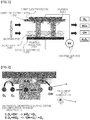
- FIG. 1 is a schematic diagram of a dielectric barrier discharge plasma-generating source containing porous dielectric member partially immersed in liquid, according to one embodiment of the present invention.
- an anion generator including the plasma-generating source according to one embodiment of the present invention is exemplified.
- the plasma-generating source includes: a plate-like first electrode 110; a plate-like second electrode 120 facing away from the first electrode 110; at least one porous dielectric member disposed between the first and second electrodes 110 and 120; a voltage source 140 for applying an AC voltage to the first electrode and the second electrode 110 and 120; a dielectric layer 150 formed on one face of at least one of the first electrode and the second electrode 110 and 120; and a liquid supply 160 containing liquid therein.
- One end of the porous dielectric member 130 is immersed in the liquid within the liquid supply 160, thereby supplying the liquid to the porous dielectric member 130.
- a plasma 200 is generated between the first electrode and the second electrode 110 and 120.
- At least one porous dielectric members 130 may be located in the plasma 200 generation region.
- the plasma is placed in a highly humid environment.
- a blowing fan may be provided to release the generated negative ions.
- the liquid may comprise water.
- High polarity liquids such as water have a high dielectric constant (about 80).
- alumina or glass material has a dielectric constant of 10 and 5, respectively.
- Porous ceramics having water impregnated therein may have a high dielectric constant of 40 to 45. Therefore, when the porous ceramic having water impregnated therein is close to the counter electrode, a high electric field may be applied to a position adjacent to the porous ceramic, thereby realizing a structure that easily generates plasma.
- FIG. 2 is a schematic diagram illustrating a state where the plasma-generating source according to an embodiment of the present invention generates a large amount of OH radicals.
- Ozone generated by the plasma reacts with H 2 O impregnated in the porous dielectric member to produce a large amount of OH radicals.
- the liquid forms liquid mist or clusters, which, in turn, may be discharged to the atmosphere.
- active species having a short survival period may be adsorbed to the liquid cluster which in turn diffuses into the atmosphere.
- the clusters act as a protective film, and, thus, the lifetime of the active species can be kept long.
- FIG. 3 to FIG. 8 are schematic diagrams of dielectric barrier discharge plasma-generating sources, each source containing a porous dielectric member partially immersed in liquid, according to further embodiments of the present invention.
- FIG. 3 illustrates a planar dielectric barrier discharge plasma-generating apparatus.
- the porous dielectric member 130 is oriented perpendicular to the horizontally-extending first and second electrodes 110 and 120. The other end of the at least one porous dielectric member 130 is spaced apart from the dielectric layer 150.
- FIG. 4 illustrates a further planar dielectric barrier discharge plasma-generating apparatus.
- the porous dielectric member 130 have vertical and horizontal portions.
- the vertical portion is oriented perpendicular to the horizontally-extending first and second electrodes 110 and 120.
- the horizontal portion of the member 130 is parallel to the horizontally-extending first and second electrodes 110 and 120.
- One end of the vertical portion of the member 130 is partially immersed in the liquid in the liquid supply 160.
- the horizontal portion of the porous dielectric member 130 is spaced apart from the dielectric layer 150.
- FIG. 5 illustrates a surface DBD (dielectric barrier discharge) plasma-generating apparatus (sDBD plasma-generating apparatus).
- the apparatus includes a plate-like dielectric layer 150; a plate-like first electrode 110 disposed on a first face of the dielectric layer; a second electrode array 120 disposed on a second face of the dielectric layer 150 opposite the first face.
- the second electrode array 120 may be configured such that a plurality of electrode bars are arranged in parallel with each other or dot-like electrodes are arranged spacedly apart from each other in a matrix form.
- At least one porous dielectric member 130 is disposed between the electrode bars or the dot-like electrodes of the second electrode array 120. When a voltage is applied to the first electrode and the second electrode array by the voltage source HV, a plasma 200 is generated between the first electrode and the second electrode array.
- One end of at least one porous dielectric member 130 may be located in the plasma generation region.
- FIG. 6 illustrates a further surface DBD (dielectric barrier discharge) plasma-generating apparatus (sDBD plasma-generating apparatus).
- the apparatus includes a plate-like dielectric layer 150; a plate-like first electrode 110 disposed on a first face of the dielectric layer 150; a second electrode array 120 disposed on a second face of the dielectric layer 150 opposite the first face.
- the second electrode array 120 may be configured such that a plurality of electrode bars are arranged in parallel with each other or dot-like electrodes are arranged spacedly apart from each other in a matrix form.
- At least one porous dielectric member 130 passes through the plate-like dielectric layer 150 and between the electrode bars or the dot-like electrodes of the second electrode array 120.
- a plasma 200 is generated between the first electrode and the second electrode array.
- At least one porous dielectric member 130 may be partially located in the plasma generation region.
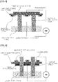
- FIG. 7 illustrates a stack-type DBD (dielectric barrier discharge) plasma-generating apparatus.
- the apparatus includes a vertically oriented plate-like first electrode layer 210; a vertically oriented plate-shaped second electrode layer 220 spaced from and parallel to the first electrode layer; and a vertically oriented plate-shaped third electrode layer 211 spaced apart from and in parallel with the second electrode layer, wherein the second electrode layer is disposed between the first electrode layer and the third electrode layer.
- the apparatus includes first and second porous dielectric members 230 disposed respectively between the first electrode layer 210 and the second electrode layer 220 and between the second electrode layer 220 and the third electrode layer 211.
- the first porous dielectric member 230 is spaced from each of the first electrode layer 210 and the second electrode layer 220.
- the second porous dielectric member 230 is separated from each of the second electrode layer 220 and the third electrode layer 211.
- a voltage is applied between the first electrode layer 210 and the second electrode layer 220 and between the third electrode layer 211 and the second electrode layer 220 by the voltage source HV, plasmas may be generated between the electrodes.
- the first and second porous dielectric members 230 may be partially located in the plasma generation region.
- FIG. 8 illustrates a cylindrical DBD (dielectric barrier discharge) plasma-generating apparatus.
- the apparatus includes a hollow cylindrical first electrode 210; a vertical bar-like second electrode 220 spaced from the first electrode, wherein the second electrode is disposed at a central position in the hollow cylindrical first electrode 210.
- the apparatus includes a hollow cylindrical porous dielectric member 230 disposed between the first and second electrodes.
- the hollow cylindrical porous dielectric member 230 may be spaced from the first and second electrodes.
- the hollow cylindrical porous dielectric member 230 surrounds the vertical bar-like second electrode 220.
- FIG. 9 is a schematic diagram illustrating a plasma-generating source according to the present invention applied as a deposition apparatus.
- the deposition apparatus a plate-like first electrode; a plate-like second electrode facing away from the first electrode; and a porous dielectric member have vertical and horizontal portions.
- the vertical portion is oriented perpendicular to the horizontally-extending first and second electrodes and.
- the horizontal portion of the member is parallel to the horizontally-extending first and second electrodes.
- One end of the vertical portion of the member is partially immersed in liquid precursor to be deposited or melted metal in in the liquid supply.
- the horizontal portion of the porous dielectric member is spaced apart from the dielectric layer.
- a substrate is disposed on the dielectric layer.
- the porous dielectric member impregnated with the molten metal or liquid precursor may react with the generated plasma, and, then, may be evaporated or atomized.
- the evaporated or atomized precursor may be deposited on a substrate.
- the use of the present apparatus can save consumption of material and have application for a larger area deposition over a conventional solid-phase deposition target.
- the deposition rate can also be increased since the molten metal or liquid precursor has a lower binding energy than that of the solid-phase deposition target. Further, it is possible to deposit an organic film even under the atmospheric pressure and low temperature condition.
Landscapes
- Physics & Mathematics (AREA)
- Engineering & Computer Science (AREA)
- Plasma & Fusion (AREA)
- Spectroscopy & Molecular Physics (AREA)
- Health & Medical Sciences (AREA)
- Life Sciences & Earth Sciences (AREA)
- Epidemiology (AREA)
- Animal Behavior & Ethology (AREA)
- General Health & Medical Sciences (AREA)
- Public Health (AREA)
- Veterinary Medicine (AREA)
- Plasma Technology (AREA)
- Physical Or Chemical Processes And Apparatus (AREA)
- Electron Sources, Ion Sources (AREA)
Claims (9)
- Générateur d'anions comprenant un appareil de génération de plasma, l'appareil de génération de plasma comprenant :- une première électrode (110) ;- une seconde électrode (120) espacée de la première électrode (110) ;- au moins un élément diélectrique poreux (130) disposé entre les première et seconde électrodes (110, 120),- une couche diélectrique (150) formée sur une première face de la première électrode (110) et/ou de la seconde électrode (120) ; et- une source de tension (140) configurée pour appliquer une tension alternative aux première électrode (110) et seconde électrode (120), et entre celles-ci,caractérisé en ce que
dans lequel, lorsqu'une tension est appliquée aux première électrode (110) et seconde électrode (120), et entre celles-ci, en utilisant la source de tension (140), un plasma de décharge formant barrière diélectrique (200) est généré entre la première électrode (110) et la seconde électrode (120),- le au moins un élément diélectrique poreux (130) est partiellement immergé dans un liquide, et en ce que- le au moins un élément diélectrique poreux (130) est partiellement situé dans la région de génération de plasma. - Appareil de génération de plasma du générateur d'anions selon la revendication 1, comprenant en outre une alimentation en liquide (160) contenant le liquide, dans lequel une extrémité de l'élément diélectrique poreux (130) est immergée dans le liquide dans l'alimentation en liquide (160) de telle sorte que l'élément diélectrique poreux (130) est imprégné du liquide.
- Appareil de génération de plasma du générateur d'anions selon la revendication 1, dans lequel chacune des première et seconde électrodes (110, 120) s'étend horizontalement, dans lequel l'élément diélectrique poreux (130) est orienté perpendiculairement aux première et seconde électrodes (110, 120), dans lequel une première extrémité de l'élément diélectrique poreux (130) est en contact avec la couche diélectrique (150), dans lequel la première extrémité de l'élément diélectrique poreux est partiellement située dans la région de génération de plasma.
- Appareil de génération de plasma du générateur d'anions selon la revendication 1, dans lequel chacune des première et seconde électrodes (110, 120) s'étend horizontalement, dans lequel l'élément diélectrique poreux (130) est orienté perpendiculairement aux première et seconde électrodes (110, 120), dans lequel une première extrémité de l'élément diélectrique poreux (130) fait face à l'opposé de la couche diélectrique (150), dans lequel la première extrémité de l'élément diélectrique poreux est partiellement située dans la région de génération de plasma.
- Appareil de génération de plasma du générateur d'anions selon l'une quelconque des revendications précédentes, dans lequel :- les première et seconde électrodes (110, 120) sont en forme de plaque et dans lequel- la seconde électrode (120) fait face à l'opposé de la première électrode (110).
- Appareil de génération de plasma du générateur d'anions selon la revendication 5, dans lequel :- la première électrode de type plaque (110) est une couche d'électrode (210) ;- la seconde électrode de type plaque (120) est une couche d'électrode (220) qui est espacée de la première couche d'électrode (210), et parallèle à celle-ci ;- l'appareil de génération de plasma du générateur d'anions comprend une troisième couche d'électrode en forme de plaque (211) espacée de la deuxième couche d'électrode (220), et parallèle à celle-ci, dans lequel la deuxième couche d'électrode (220) est disposée entre la première couche d'électrode (210) et la troisième couche d'électrode ;- le au moins un élément diélectrique poreux comprend des premier et second éléments diélectriques poreux (230) disposés respectivement entre la première couche d'électrode (210) et la deuxième couche d'électrode (220) et entre la deuxième couche d'électrode (220) et la troisième couche d'électrode, dans lequel le premier élément diélectrique poreux (230) est espacé de chacune de la première couche d'électrode (210) et de la deuxième couche d'électrode (220), dans lequel le second élément diélectrique poreux (230) est espacé de chacune de la deuxième couche d'électrode (220) et de la troisième couche d'électrode,- la source de tension est configurée pour appliquer une tension aux première couche d'électrode (210) et deuxième couche d'électrode (220), et entre celles-ci, et aux première couche d'électrode (210) et troisième couche d'électrode, et entre celles-ci,- chacun des premier et second éléments diélectriques poreux (230) est partiellement immergé dans un liquide,- dans lequel, lorsque la tension est appliquée aux première couche d'électrode (210) et deuxième couche d'électrode (220), et entre celles-ci, et aux troisième couche d'électrode et deuxième couche d'électrode (220), et entre celles-ci, en utilisant la source de tension, un premier plasma de décharge formant barrière diélectrique (200) est généré entre la première couche d'électrode (210) et la deuxième couche d'électrode (220) et un second plasma de décharge formant barrière diélectrique (200) est généré entre la troisième couche d'électrode et la deuxième couche d'électrode (220), et dans lequel- le premier élément diélectrique poreux (230) est partiellement situé dans la première région de génération de plasma, et le second élément diélectrique poreux (230) est partiellement situé dans la seconde région de génération de plasma.
- Appareil de génération de plasma du générateur d'anions selon la revendication 1, dans lequel :- la première électrode (110, 210) est creuse et cylindrique ;- la seconde électrode (120, 220) est verticale et de type barre et espacée de la première électrode (110, 210), dans lequel la seconde électrode (120, 220) est disposée à une position centrale dans la première électrode cylindrique creuse (110, 210) ;- l'élément diélectrique poreux (130, 230) est creux et cylindrique et disposé entre les première et seconde électrodes (110, 210; 120, 220), dans lequel l'élément diélectrique poreux cylindrique creux (130, 230) est espacé des première et seconde électrodes (110, 210; 120, 220), dans lequel l'élément diélectrique poreux cylindrique creux (130, 230) entoure la seconde électrode verticale de type barre (120, 220), et dans lequel- la source de tension est configurée pour appliquer une tension aux première et seconde électrodes (110, 210 ; 120, 220), et entre celles-ci.
- Appareil de génération de plasma du générateur d'anions selon la revendication 6 ou 7, comprenant en outre une alimentation en liquide (260) contenant le liquide, dans lequel une extrémité de l'élément diélectrique poreux (230) est immergée dans le liquide dans l'alimentation en liquide (260) de telle sorte que l'élément diélectrique poreux (230) est imprégné du liquide.
- Appareil de génération de plasma du générateur d'anions selon l'une quelconque des revendications 1, 6 et 7, dans lequel le liquide inclut du peroxyde d'hydrogène.
Priority Applications (1)
| Application Number | Priority Date | Filing Date | Title |
|---|---|---|---|
| EP21197401.9A EP3952618B1 (fr) | 2015-02-05 | 2016-02-05 | Générateur d'anions |
Applications Claiming Priority (2)
| Application Number | Priority Date | Filing Date | Title |
|---|---|---|---|
| KR1020150017875A KR101933258B1 (ko) | 2015-02-05 | 2015-02-05 | 다공질 유전체를 포함하는 플라즈마 발생원 |
| PCT/KR2016/001311 WO2016126140A1 (fr) | 2015-02-05 | 2016-02-05 | Source de plasma comprenant un diélectrique poreux |
Related Child Applications (2)
| Application Number | Title | Priority Date | Filing Date |
|---|---|---|---|
| EP21197401.9A Division EP3952618B1 (fr) | 2015-02-05 | 2016-02-05 | Générateur d'anions |
| EP21197401.9A Division-Into EP3952618B1 (fr) | 2015-02-05 | 2016-02-05 | Générateur d'anions |
Publications (3)
| Publication Number | Publication Date |
|---|---|
| EP3255960A1 EP3255960A1 (fr) | 2017-12-13 |
| EP3255960A4 EP3255960A4 (fr) | 2018-10-10 |
| EP3255960B1 true EP3255960B1 (fr) | 2021-10-27 |
Family
ID=56564382
Family Applications (2)
| Application Number | Title | Priority Date | Filing Date |
|---|---|---|---|
| EP16746881.8A Active EP3255960B1 (fr) | 2015-02-05 | 2016-02-05 | Générateur d'anions comprenant une source de plasma comprenant un diélectrique poreux |
| EP21197401.9A Active EP3952618B1 (fr) | 2015-02-05 | 2016-02-05 | Générateur d'anions |
Family Applications After (1)
| Application Number | Title | Priority Date | Filing Date |
|---|---|---|---|
| EP21197401.9A Active EP3952618B1 (fr) | 2015-02-05 | 2016-02-05 | Générateur d'anions |
Country Status (5)
| Country | Link |
|---|---|
| EP (2) | EP3255960B1 (fr) |
| JP (1) | JP6581661B2 (fr) |
| KR (1) | KR101933258B1 (fr) |
| CN (1) | CN107211520B (fr) |
| WO (1) | WO2016126140A1 (fr) |
Families Citing this family (17)
| Publication number | Priority date | Publication date | Assignee | Title |
|---|---|---|---|---|
| KR101858360B1 (ko) * | 2016-11-08 | 2018-06-28 | 한국기초과학지원연구원 | 공기를 이용한 질소산화물 발생이 억제된 오존 발생 장치 |
| WO2020064105A1 (fr) * | 2018-09-26 | 2020-04-02 | L'oreal | Dispositif de génération de plasma froid à filtre à ozone poreux |
| CN109671602B (zh) * | 2018-11-15 | 2021-05-21 | 温州职业技术学院 | 基于热电子放电的复合电子源 |
| KR102274231B1 (ko) * | 2019-05-27 | 2021-07-06 | 광운대학교 산학협력단 | 오존 프리 소독용 대기압 플라즈마 처리시스템 |
| KR102146200B1 (ko) * | 2019-10-14 | 2020-08-19 | 배준형 | 고밀도 융합 플라즈마 살균 및 탈취기 |
| CN111010791A (zh) * | 2019-12-10 | 2020-04-14 | 清华大学 | 基于多孔介质放电的等离子体发生装置 |
| KR102533737B1 (ko) | 2020-02-27 | 2023-05-18 | 한국핵융합에너지연구원 | 플라즈마 발생 장치 |
| KR102455730B1 (ko) | 2020-04-24 | 2022-10-20 | 한국핵융합에너지연구원 | 열구배 완화 플라즈마 발생 장치 |
| KR20210132275A (ko) | 2020-04-24 | 2021-11-04 | 한국핵융합에너지연구원 | 활성종 조성 조절이 가능한 플라즈마 발생 장치 |
| KR102557265B1 (ko) | 2020-12-07 | 2023-07-19 | 아프로코리아 주식회사 | 무오존 음이온 발생 플라즈마 의료기기 |
| CN113543442B (zh) * | 2021-06-23 | 2023-05-23 | 中国人民解放军空军工程大学 | 多层阵列式微孔放电等离子体发生装置及发生方法 |
| KR102731165B1 (ko) * | 2021-09-17 | 2024-11-18 | 주식회사 아이포러스 | 수산화라디칼을 포함한 플라즈마 발생장치 |
| KR102738560B1 (ko) | 2021-12-23 | 2024-12-10 | 한국핵융합에너지연구원 | 플라즈마 살균장치 및 이를 포함하는 살균방법 |
| KR20230108638A (ko) | 2022-01-11 | 2023-07-18 | 삼성전자주식회사 | 공기 정화 장치 및 공기 정화 방법 |
| KR20240114128A (ko) | 2023-01-16 | 2024-07-23 | 주식회사 오존에이드 | 플라즈마 생성 시스템 |
| CN116531544B (zh) * | 2023-05-26 | 2026-03-10 | 重庆交通大学绿色航空技术研究院 | 基于等离子体流动控制的无叶片式空气杀菌装置 |
| CN119113402B (zh) * | 2024-09-03 | 2025-05-06 | 南京工业大学 | 皮肤表面处理应用的阻抗匹配式柔性sdbd电极 |
Family Cites Families (12)
| Publication number | Priority date | Publication date | Assignee | Title |
|---|---|---|---|---|
| HU224394B1 (hu) * | 2001-07-17 | 2005-08-29 | G.I.C. Kft. | Eljárás és berendezés elektromosan vezetõképes, vizes hulladékoldatok szervesanyag-tartalmának víz alatti elbontására |
| JP2007000695A (ja) * | 2005-06-21 | 2007-01-11 | Ricoh Elemex Corp | 空気清浄機 |
| EP1968740B8 (fr) * | 2005-12-17 | 2017-02-22 | AirInSpace S.E. | Dispositifs de purification d air |
| JP2009054557A (ja) * | 2007-08-24 | 2009-03-12 | Osamu Sakai | 液体中プラズマ発生装置 |
| US8994270B2 (en) * | 2008-05-30 | 2015-03-31 | Colorado State University Research Foundation | System and methods for plasma application |
| JP5360966B2 (ja) * | 2009-01-28 | 2013-12-04 | 国立大学法人愛媛大学 | 液中プラズマ発生装置および液中プラズマ発生方法 |
| JP5445966B2 (ja) * | 2010-06-30 | 2014-03-19 | 国立大学法人名古屋大学 | 水処理方法および水処理装置 |
| JP2012204248A (ja) * | 2011-03-28 | 2012-10-22 | Panasonic Corp | プラズマ発生装置及びこれを用いた洗浄浄化装置 |
| KR101256577B1 (ko) * | 2011-08-25 | 2013-04-19 | 한국기초과학지원연구원 | 수중 방전 전극 및 이를 포함하는 수중 모세관 플라즈마 방전 장치 |
| FR2983471B1 (fr) * | 2011-12-01 | 2017-03-10 | Beewair | Procede de traitement d'effluents dans un lit de microbilles par plasma froid et photocatalyse |
| JP6008359B2 (ja) * | 2012-03-30 | 2016-10-19 | 公立大学法人大阪市立大学 | 液中プラズマ発生装置、被処理液浄化装置及びイオン含有液体生成装置 |
| CN103759275B (zh) * | 2013-12-27 | 2016-01-27 | 浙江大学 | 等离子体强化多孔介质燃烧处理有机废气的装置及方法 |
-
2015
- 2015-02-05 KR KR1020150017875A patent/KR101933258B1/ko active Active
-
2016
- 2016-02-05 EP EP16746881.8A patent/EP3255960B1/fr active Active
- 2016-02-05 JP JP2017540887A patent/JP6581661B2/ja active Active
- 2016-02-05 CN CN201680008726.7A patent/CN107211520B/zh active Active
- 2016-02-05 WO PCT/KR2016/001311 patent/WO2016126140A1/fr not_active Ceased
- 2016-02-05 EP EP21197401.9A patent/EP3952618B1/fr active Active
Also Published As
| Publication number | Publication date |
|---|---|
| WO2016126140A1 (fr) | 2016-08-11 |
| EP3255960A1 (fr) | 2017-12-13 |
| JP6581661B2 (ja) | 2019-09-25 |
| EP3952618A1 (fr) | 2022-02-09 |
| KR20160096353A (ko) | 2016-08-16 |
| CN107211520A (zh) | 2017-09-26 |
| EP3952618B1 (fr) | 2022-10-05 |
| EP3255960A4 (fr) | 2018-10-10 |
| CN107211520B (zh) | 2019-11-19 |
| JP2018504757A (ja) | 2018-02-15 |
| KR101933258B1 (ko) | 2019-03-15 |
Similar Documents
| Publication | Publication Date | Title |
|---|---|---|
| EP3255960B1 (fr) | Générateur d'anions comprenant une source de plasma comprenant un diélectrique poreux | |
| CN106572586B (zh) | 一种产生均匀、稳定射流等离子体的装置 | |
| US7533629B2 (en) | Arrangement, method and electrode for generating a plasma | |
| CN107233786B (zh) | 一种螺旋沿面型结构的低温等离子体发生器 | |
| CN102026468A (zh) | 一种介质阻挡电晕放电反应器 | |
| WO2008040154A1 (fr) | Traitement au plasma de diffusion et traitement de matériaux | |
| CN203167413U (zh) | 大气压弥散型冷等离子体发生装置 | |
| JP2010541167A5 (fr) | ||
| RU2009131534A (ru) | Устройство для плазменной обработки | |
| JP2022530751A (ja) | プラズマ表面除菌剤とその方法 | |
| KR101327825B1 (ko) | 플라즈마를 이용하는 알루미늄 표면개질방법 | |
| CN103052250A (zh) | 大气压弥散型冷等离子体发生装置 | |
| KR20130118903A (ko) | 플라즈마 발생 장치 및 플라즈마 발생 방법 | |
| WO2005079123A2 (fr) | Dispositif generateur de plasma et procede de traitement d'un milieu gazeux | |
| JP2009505342A (ja) | プラズマ発生装置及びプラズマ発生方法 | |
| KR101155554B1 (ko) | 플라즈마 조사 장치 | |
| JP2015088218A (ja) | イオンビーム処理装置及び中和器 | |
| RU2748931C1 (ru) | Устройство для дезинфекции рук, поверхностей предметов и воздуха | |
| WO2019146799A2 (fr) | Dispositif de génération d'ions pour la décomposition de matière organique, et dispositif de décomposition de matière organique | |
| US20070131539A1 (en) | Combination heater/generator for generating negatively charged oxygen atoms | |
| KR100761962B1 (ko) | 상압 플라즈마 발생장치 | |
| KR102211053B1 (ko) | 유전체 장벽 방전 플라즈마 반응기 및 이를 구비한 가스처리장치 | |
| US20080193327A1 (en) | Device For The Treatment Of A Gaseous Medium With Plasma And Method Of Protecting Such A Device Against Inflammation And/Or Explosion | |
| CN118160781A (zh) | 一种物料消杀装置 | |
| KR200427719Y1 (ko) | 상압 플라즈마 발생장치 |
Legal Events
| Date | Code | Title | Description |
|---|---|---|---|
| STAA | Information on the status of an ep patent application or granted ep patent |
Free format text: STATUS: THE INTERNATIONAL PUBLICATION HAS BEEN MADE |
|
| PUAI | Public reference made under article 153(3) epc to a published international application that has entered the european phase |
Free format text: ORIGINAL CODE: 0009012 |
|
| STAA | Information on the status of an ep patent application or granted ep patent |
Free format text: STATUS: REQUEST FOR EXAMINATION WAS MADE |
|
| 17P | Request for examination filed |
Effective date: 20170804 |
|
| AK | Designated contracting states |
Kind code of ref document: A1 Designated state(s): AL AT BE BG CH CY CZ DE DK EE ES FI FR GB GR HR HU IE IS IT LI LT LU LV MC MK MT NL NO PL PT RO RS SE SI SK SM TR |
|
| AX | Request for extension of the european patent |
Extension state: BA ME |
|
| DAV | Request for validation of the european patent (deleted) | ||
| DAX | Request for extension of the european patent (deleted) | ||
| A4 | Supplementary search report drawn up and despatched |
Effective date: 20180910 |
|
| RIC1 | Information provided on ipc code assigned before grant |
Ipc: H05H 1/24 20060101AFI20180904BHEP |
|
| RAP1 | Party data changed (applicant data changed or rights of an application transferred) |
Owner name: KOREA INSTITUTE OF FUSION ENERGY |
|
| GRAP | Despatch of communication of intention to grant a patent |
Free format text: ORIGINAL CODE: EPIDOSNIGR1 |
|
| STAA | Information on the status of an ep patent application or granted ep patent |
Free format text: STATUS: GRANT OF PATENT IS INTENDED |
|
| INTG | Intention to grant announced |
Effective date: 20210518 |
|
| GRAS | Grant fee paid |
Free format text: ORIGINAL CODE: EPIDOSNIGR3 |
|
| GRAA | (expected) grant |
Free format text: ORIGINAL CODE: 0009210 |
|
| STAA | Information on the status of an ep patent application or granted ep patent |
Free format text: STATUS: THE PATENT HAS BEEN GRANTED |
|
| AK | Designated contracting states |
Kind code of ref document: B1 Designated state(s): AL AT BE BG CH CY CZ DE DK EE ES FI FR GB GR HR HU IE IS IT LI LT LU LV MC MK MT NL NO PL PT RO RS SE SI SK SM TR |
|
| REG | Reference to a national code |
Ref country code: GB Ref legal event code: FG4D |
|
| REG | Reference to a national code |
Ref country code: CH Ref legal event code: EP |
|
| REG | Reference to a national code |
Ref country code: AT Ref legal event code: REF Ref document number: 1443124 Country of ref document: AT Kind code of ref document: T Effective date: 20211115 |
|
| REG | Reference to a national code |
Ref country code: DE Ref legal event code: R096 Ref document number: 602016065412 Country of ref document: DE |
|
| REG | Reference to a national code |
Ref country code: IE Ref legal event code: FG4D |
|
| REG | Reference to a national code |
Ref country code: LT Ref legal event code: MG9D |
|
| REG | Reference to a national code |
Ref country code: NL Ref legal event code: MP Effective date: 20211027 |
|
| REG | Reference to a national code |
Ref country code: AT Ref legal event code: MK05 Ref document number: 1443124 Country of ref document: AT Kind code of ref document: T Effective date: 20211027 |
|
| PG25 | Lapsed in a contracting state [announced via postgrant information from national office to epo] |
Ref country code: RS Free format text: LAPSE BECAUSE OF FAILURE TO SUBMIT A TRANSLATION OF THE DESCRIPTION OR TO PAY THE FEE WITHIN THE PRESCRIBED TIME-LIMIT Effective date: 20211027 Ref country code: LT Free format text: LAPSE BECAUSE OF FAILURE TO SUBMIT A TRANSLATION OF THE DESCRIPTION OR TO PAY THE FEE WITHIN THE PRESCRIBED TIME-LIMIT Effective date: 20211027 Ref country code: FI Free format text: LAPSE BECAUSE OF FAILURE TO SUBMIT A TRANSLATION OF THE DESCRIPTION OR TO PAY THE FEE WITHIN THE PRESCRIBED TIME-LIMIT Effective date: 20211027 Ref country code: BG Free format text: LAPSE BECAUSE OF FAILURE TO SUBMIT A TRANSLATION OF THE DESCRIPTION OR TO PAY THE FEE WITHIN THE PRESCRIBED TIME-LIMIT Effective date: 20220127 Ref country code: AT Free format text: LAPSE BECAUSE OF FAILURE TO SUBMIT A TRANSLATION OF THE DESCRIPTION OR TO PAY THE FEE WITHIN THE PRESCRIBED TIME-LIMIT Effective date: 20211027 |
|
| PG25 | Lapsed in a contracting state [announced via postgrant information from national office to epo] |
Ref country code: IS Free format text: LAPSE BECAUSE OF FAILURE TO SUBMIT A TRANSLATION OF THE DESCRIPTION OR TO PAY THE FEE WITHIN THE PRESCRIBED TIME-LIMIT Effective date: 20220227 Ref country code: SE Free format text: LAPSE BECAUSE OF FAILURE TO SUBMIT A TRANSLATION OF THE DESCRIPTION OR TO PAY THE FEE WITHIN THE PRESCRIBED TIME-LIMIT Effective date: 20211027 Ref country code: PT Free format text: LAPSE BECAUSE OF FAILURE TO SUBMIT A TRANSLATION OF THE DESCRIPTION OR TO PAY THE FEE WITHIN THE PRESCRIBED TIME-LIMIT Effective date: 20220228 Ref country code: PL Free format text: LAPSE BECAUSE OF FAILURE TO SUBMIT A TRANSLATION OF THE DESCRIPTION OR TO PAY THE FEE WITHIN THE PRESCRIBED TIME-LIMIT Effective date: 20211027 Ref country code: NO Free format text: LAPSE BECAUSE OF FAILURE TO SUBMIT A TRANSLATION OF THE DESCRIPTION OR TO PAY THE FEE WITHIN THE PRESCRIBED TIME-LIMIT Effective date: 20220127 Ref country code: NL Free format text: LAPSE BECAUSE OF FAILURE TO SUBMIT A TRANSLATION OF THE DESCRIPTION OR TO PAY THE FEE WITHIN THE PRESCRIBED TIME-LIMIT Effective date: 20211027 Ref country code: LV Free format text: LAPSE BECAUSE OF FAILURE TO SUBMIT A TRANSLATION OF THE DESCRIPTION OR TO PAY THE FEE WITHIN THE PRESCRIBED TIME-LIMIT Effective date: 20211027 Ref country code: HR Free format text: LAPSE BECAUSE OF FAILURE TO SUBMIT A TRANSLATION OF THE DESCRIPTION OR TO PAY THE FEE WITHIN THE PRESCRIBED TIME-LIMIT Effective date: 20211027 Ref country code: GR Free format text: LAPSE BECAUSE OF FAILURE TO SUBMIT A TRANSLATION OF THE DESCRIPTION OR TO PAY THE FEE WITHIN THE PRESCRIBED TIME-LIMIT Effective date: 20220128 Ref country code: ES Free format text: LAPSE BECAUSE OF FAILURE TO SUBMIT A TRANSLATION OF THE DESCRIPTION OR TO PAY THE FEE WITHIN THE PRESCRIBED TIME-LIMIT Effective date: 20211027 |
|
| REG | Reference to a national code |
Ref country code: DE Ref legal event code: R097 Ref document number: 602016065412 Country of ref document: DE |
|
| PG25 | Lapsed in a contracting state [announced via postgrant information from national office to epo] |
Ref country code: SM Free format text: LAPSE BECAUSE OF FAILURE TO SUBMIT A TRANSLATION OF THE DESCRIPTION OR TO PAY THE FEE WITHIN THE PRESCRIBED TIME-LIMIT Effective date: 20211027 Ref country code: SK Free format text: LAPSE BECAUSE OF FAILURE TO SUBMIT A TRANSLATION OF THE DESCRIPTION OR TO PAY THE FEE WITHIN THE PRESCRIBED TIME-LIMIT Effective date: 20211027 Ref country code: RO Free format text: LAPSE BECAUSE OF FAILURE TO SUBMIT A TRANSLATION OF THE DESCRIPTION OR TO PAY THE FEE WITHIN THE PRESCRIBED TIME-LIMIT Effective date: 20211027 Ref country code: EE Free format text: LAPSE BECAUSE OF FAILURE TO SUBMIT A TRANSLATION OF THE DESCRIPTION OR TO PAY THE FEE WITHIN THE PRESCRIBED TIME-LIMIT Effective date: 20211027 Ref country code: DK Free format text: LAPSE BECAUSE OF FAILURE TO SUBMIT A TRANSLATION OF THE DESCRIPTION OR TO PAY THE FEE WITHIN THE PRESCRIBED TIME-LIMIT Effective date: 20211027 Ref country code: CZ Free format text: LAPSE BECAUSE OF FAILURE TO SUBMIT A TRANSLATION OF THE DESCRIPTION OR TO PAY THE FEE WITHIN THE PRESCRIBED TIME-LIMIT Effective date: 20211027 |
|
| PLBE | No opposition filed within time limit |
Free format text: ORIGINAL CODE: 0009261 |
|
| STAA | Information on the status of an ep patent application or granted ep patent |
Free format text: STATUS: NO OPPOSITION FILED WITHIN TIME LIMIT |
|
| PG25 | Lapsed in a contracting state [announced via postgrant information from national office to epo] |
Ref country code: MC Free format text: LAPSE BECAUSE OF FAILURE TO SUBMIT A TRANSLATION OF THE DESCRIPTION OR TO PAY THE FEE WITHIN THE PRESCRIBED TIME-LIMIT Effective date: 20211027 |
|
| 26N | No opposition filed |
Effective date: 20220728 |
|
| PG25 | Lapsed in a contracting state [announced via postgrant information from national office to epo] |
Ref country code: LU Free format text: LAPSE BECAUSE OF NON-PAYMENT OF DUE FEES Effective date: 20220205 Ref country code: AL Free format text: LAPSE BECAUSE OF FAILURE TO SUBMIT A TRANSLATION OF THE DESCRIPTION OR TO PAY THE FEE WITHIN THE PRESCRIBED TIME-LIMIT Effective date: 20211027 |
|
| PG25 | Lapsed in a contracting state [announced via postgrant information from national office to epo] |
Ref country code: SI Free format text: LAPSE BECAUSE OF FAILURE TO SUBMIT A TRANSLATION OF THE DESCRIPTION OR TO PAY THE FEE WITHIN THE PRESCRIBED TIME-LIMIT Effective date: 20211027 |
|
| PG25 | Lapsed in a contracting state [announced via postgrant information from national office to epo] |
Ref country code: IE Free format text: LAPSE BECAUSE OF NON-PAYMENT OF DUE FEES Effective date: 20220205 |
|
| PG25 | Lapsed in a contracting state [announced via postgrant information from national office to epo] |
Ref country code: IT Free format text: LAPSE BECAUSE OF FAILURE TO SUBMIT A TRANSLATION OF THE DESCRIPTION OR TO PAY THE FEE WITHIN THE PRESCRIBED TIME-LIMIT Effective date: 20211027 |
|
| PG25 | Lapsed in a contracting state [announced via postgrant information from national office to epo] |
Ref country code: HU Free format text: LAPSE BECAUSE OF FAILURE TO SUBMIT A TRANSLATION OF THE DESCRIPTION OR TO PAY THE FEE WITHIN THE PRESCRIBED TIME-LIMIT; INVALID AB INITIO Effective date: 20160205 |
|
| PG25 | Lapsed in a contracting state [announced via postgrant information from national office to epo] |
Ref country code: MK Free format text: LAPSE BECAUSE OF FAILURE TO SUBMIT A TRANSLATION OF THE DESCRIPTION OR TO PAY THE FEE WITHIN THE PRESCRIBED TIME-LIMIT Effective date: 20211027 Ref country code: CY Free format text: LAPSE BECAUSE OF FAILURE TO SUBMIT A TRANSLATION OF THE DESCRIPTION OR TO PAY THE FEE WITHIN THE PRESCRIBED TIME-LIMIT Effective date: 20211027 |
|
| PG25 | Lapsed in a contracting state [announced via postgrant information from national office to epo] |
Ref country code: MT Free format text: LAPSE BECAUSE OF FAILURE TO SUBMIT A TRANSLATION OF THE DESCRIPTION OR TO PAY THE FEE WITHIN THE PRESCRIBED TIME-LIMIT Effective date: 20211027 |
|
| PG25 | Lapsed in a contracting state [announced via postgrant information from national office to epo] |
Ref country code: TR Free format text: LAPSE BECAUSE OF FAILURE TO SUBMIT A TRANSLATION OF THE DESCRIPTION OR TO PAY THE FEE WITHIN THE PRESCRIBED TIME-LIMIT Effective date: 20211027 |
|
| PGFP | Annual fee paid to national office [announced via postgrant information from national office to epo] |
Ref country code: GB Payment date: 20251222 Year of fee payment: 11 |
|
| PGFP | Annual fee paid to national office [announced via postgrant information from national office to epo] |
Ref country code: FR Payment date: 20251223 Year of fee payment: 11 |
|
| PGFP | Annual fee paid to national office [announced via postgrant information from national office to epo] |
Ref country code: BE Payment date: 20251229 Year of fee payment: 11 |
|
| REG | Reference to a national code |
Ref country code: CH Ref legal event code: U11 Free format text: ST27 STATUS EVENT CODE: U-0-0-U10-U11 (AS PROVIDED BY THE NATIONAL OFFICE) Effective date: 20260301 |
|
| PGFP | Annual fee paid to national office [announced via postgrant information from national office to epo] |
Ref country code: DE Payment date: 20251222 Year of fee payment: 11 |
|
| PGFP | Annual fee paid to national office [announced via postgrant information from national office to epo] |
Ref country code: CH Payment date: 20260301 Year of fee payment: 11 |