EP3256056B1 - Système de chirurgie endoscopique formé d'une part par une pluralité d'agrafes et d'autre part par un applicateur endoscopique - Google Patents
Système de chirurgie endoscopique formé d'une part par une pluralité d'agrafes et d'autre part par un applicateur endoscopique Download PDFInfo
- Publication number
- EP3256056B1 EP3256056B1 EP16707917.7A EP16707917A EP3256056B1 EP 3256056 B1 EP3256056 B1 EP 3256056B1 EP 16707917 A EP16707917 A EP 16707917A EP 3256056 B1 EP3256056 B1 EP 3256056B1
- Authority
- EP
- European Patent Office
- Prior art keywords
- staple
- staples
- section
- sleeve
- endoscopic
- Prior art date
- Legal status (The legal status is an assumption and is not a legal conclusion. Google has not performed a legal analysis and makes no representation as to the accuracy of the status listed.)
- Active
Links
Images


Classifications
-
- A—HUMAN NECESSITIES
- A61—MEDICAL OR VETERINARY SCIENCE; HYGIENE
- A61B—DIAGNOSIS; SURGERY; IDENTIFICATION
- A61B1/00—Instruments for performing medical examinations of the interior of cavities or tubes of the body by visual or photographical inspection, e.g. endoscopes; Illuminating arrangements therefor
- A61B1/00064—Constructional details of the endoscope body
- A61B1/00071—Insertion part of the endoscope body
- A61B1/0008—Insertion part of the endoscope body characterised by distal tip features
-
- A—HUMAN NECESSITIES
- A61—MEDICAL OR VETERINARY SCIENCE; HYGIENE
- A61B—DIAGNOSIS; SURGERY; IDENTIFICATION
- A61B17/00—Surgical instruments, devices or methods
- A61B17/064—Surgical staples, i.e. penetrating the tissue
- A61B17/0644—Surgical staples, i.e. penetrating the tissue penetrating the tissue, deformable to closed position
-
- A—HUMAN NECESSITIES
- A61—MEDICAL OR VETERINARY SCIENCE; HYGIENE
- A61B—DIAGNOSIS; SURGERY; IDENTIFICATION
- A61B17/00—Surgical instruments, devices or methods
- A61B17/068—Surgical staplers, e.g. containing multiple staples or clamps
- A61B17/0682—Surgical staplers, e.g. containing multiple staples or clamps for applying U-shaped staples or clamps, e.g. without a forming anvil
- A61B17/0684—Surgical staplers, e.g. containing multiple staples or clamps for applying U-shaped staples or clamps, e.g. without a forming anvil having a forming anvil staying above the tissue during stapling
-
- A—HUMAN NECESSITIES
- A61—MEDICAL OR VETERINARY SCIENCE; HYGIENE
- A61B—DIAGNOSIS; SURGERY; IDENTIFICATION
- A61B17/00—Surgical instruments, devices or methods
- A61B17/068—Surgical staplers, e.g. containing multiple staples or clamps
- A61B17/072—Surgical staplers, e.g. containing multiple staples or clamps for applying a row of staples in a single action, e.g. the staples being applied simultaneously
- A61B17/07207—Surgical staplers, e.g. containing multiple staples or clamps for applying a row of staples in a single action, e.g. the staples being applied simultaneously the staples being applied sequentially
-
- A—HUMAN NECESSITIES
- A61—MEDICAL OR VETERINARY SCIENCE; HYGIENE
- A61B—DIAGNOSIS; SURGERY; IDENTIFICATION
- A61B17/00—Surgical instruments, devices or methods
- A61B17/00234—Surgical instruments, devices or methods for minimally invasive surgery
- A61B2017/00292—Surgical instruments, devices or methods for minimally invasive surgery mounted on or guided by flexible, e.g. catheter-like, means
- A61B2017/00296—Surgical instruments, devices or methods for minimally invasive surgery mounted on or guided by flexible, e.g. catheter-like, means mounted on an endoscope
-
- A—HUMAN NECESSITIES
- A61—MEDICAL OR VETERINARY SCIENCE; HYGIENE
- A61B—DIAGNOSIS; SURGERY; IDENTIFICATION
- A61B17/00—Surgical instruments, devices or methods
- A61B17/068—Surgical staplers, e.g. containing multiple staples or clamps
- A61B17/072—Surgical staplers, e.g. containing multiple staples or clamps for applying a row of staples in a single action, e.g. the staples being applied simultaneously
- A61B2017/07214—Stapler heads
- A61B2017/07271—Stapler heads characterised by its cartridge
-
- A—HUMAN NECESSITIES
- A61—MEDICAL OR VETERINARY SCIENCE; HYGIENE
- A61B—DIAGNOSIS; SURGERY; IDENTIFICATION
- A61B17/00—Surgical instruments, devices or methods
- A61B17/068—Surgical staplers, e.g. containing multiple staples or clamps
- A61B17/072—Surgical staplers, e.g. containing multiple staples or clamps for applying a row of staples in a single action, e.g. the staples being applied simultaneously
- A61B2017/07214—Stapler heads
- A61B2017/07278—Stapler heads characterised by its sled or its staple holder
Definitions
- the present invention relates to the field of endoscopic staple applicators.
- Such an applicator allows surgeons to place staples in order to hold tissues during an endoscopic procedure.
- An endoscopic staple applier is configured to retain a plurality of staples, including ligature staples, in a staple channel and a jaw system for applying a staple.
- the jaw system is connected at the distal end of the staple channel and at the proximal end to a control handle.
- the staple When ejected, the staple deforms to tighten the body tissue.
- Each staple has a generally U-shaped body having an upper crossbar having adjoining staple legs on opposite sides of the upper crossbar.
- a cartridge housing receiving a plurality of staples is arranged in a row for longitudinal movement therethrough.
- An anvil is mounted on said housing.
- the forwardmost staple is moved into contact with said anvil and then tilted from a transverse orientation to a longitudinal orientation and then deformed by pressure on said anvil to secure the staple.
- the patent application is also known US2009272786 describing a surgical stapler that includes an elongated tubular shaft extending distally from the handle.
- the tubular shaft includes a proximal end secured to the handle and a distal end having a deployment opening formed therein.
- a staple deployment assembly is disposed within the shaft for discharging staples from the deployment opening located at the distal end of the shaft, the staple deployment assembly supporting a staple such that a longitudinal axis of the staple is aligned with a longitudinal axis of the shaft.
- a surgical stapler which comprises a staple application section containing a plurality of staples, a staple pusher incorporated in the staple application section, for applying the staples, an anvil section for deforming the staples, in order to staple body tissues together, an operation section for operating the staple pusher and the anvil section, an observation window located near the anvil section, and an eyepiece section for displaying images provided by the observation window.
- the patent application is also known US2009272783 describing a surgical stapling device for deploying staples connected by a suture to tissue includes a handle having a staple actuating mechanism, a tubular support rod having a longitudinal axis and extending from the handle, and a staple cartridge mounted on the support rod and connected to the staple actuating mechanism for applying one or more staples to the tissue.
- the cartridge has a cartridge housing adapted to receive a plurality of staples in a row for longitudinal movement therethrough and an anvil mounted on the housing.
- the cartridge further includes a mechanism for advancing the forward-most staple of the row into engagement with the anvil, and a suture guide supporting a length of suture that extends into a loop for attachment to the staples when secured to tissue.
- the patent application is also known US2009072006 relating to a surgical stapler may include at least one staple, a pusher, and a flared arm; wherein movement of at least one of the flared arm and the pusher relative to the other causes the flared arm to contact and then flare at least one staple.
- the patent application is also known US2009275957 which relates to a tissue apposition system comprising a delivery assembly to which a tissue clamp is selectively attached for deployment and application of the tissue clamp.
- the tissue clamp is shaped and sized to engage spaced locations along a stretch of tissue and, upon rotation, bring the spaced locations together in apposition to thereby create a fold of tissue.
- the staple magazine often has a fairly large longitudinal footprint, making the solution poorly suited for use with flexible endoscopes.
- the present invention relates, in its most general sense, to an endoscopic surgery system having the characteristics set out in claim 1.
- the control member comprises a rigid hollow tubular sleeve (1).
- a rigid rod (2) of polygonal cross-section slides longitudinally inside this sleeve (1) having a guide channel of complementary square section.
- This sleeve (1) has at its distal end a chamfer (3) defining a surface inclined relative to a longitudinal plane, leading to a nipple (4) extending perpendicular to the longitudinal axis.
- the chamfer (3) and the nipple (4) form a receiving area for a clip (5) having a general “horseshoe” shape.
- the staple has a shape, when viewed from the front and before stapling, a general semi-annular or "horseshoe" shape.
- the staple is formed by a steel cutout but it can also be formed by shaping a metal wire or a biodegradable material.
- This median plane (6) is defined by an axis parallel to the longitudinal axis of the sleeve (1) and by the axis of the nipple (4).
- the connecting section (7) simply designates the part between the two branches (8, 9). There is no separation between this area referred to as the connecting section (7) and the branches (8, 9) in the example described.
- This middle section (7) has a semi-tubular shape and is produced by deformation of the material towards the rear with a cylindrical matrix.
- the semi-tubular shape of the middle section (7) allows the positioning of a guide member provided at the end of an endoscopic instrument, in order to facilitate the handling of the staple at the time of its installation.
- Each of the two branches (8, 9) has a pointed end (10, 11) in the shape of a hook, extending in front of the transverse plane containing the corresponding branch (8, 9).
- the tangent to the pointed end (11, 21) forms, with respect to the normal to the transverse plane, an angle greater than 0° and less than 90°, and preferably between 5° and 50°.
- This pointed end makes it possible to hook the tissues in the vicinity of the staple placement area, and to exert lateral traction to bring them closer together before stapling.
- the angle formed by the tangent is large, the tissues are encouraged to be drawn in without being perforated. If the angle is smaller, the pointed end is encouraged to penetrate the tissues.
- the two branches (8, 9) also each carry a hook (12, 13) projecting in front of the transverse plane, and positioned closer to the pointed end (10, 11) than said connecting section (7).
- the unrolled length of the hooking point (10, 11) is substantially equal to the unrolled length of the hook (12, 13).
- This hook (12, 13) has a pinching surface (14, 15) substantially parallel to the transverse plane. This pinching surface (14, 15) will rest on either side of the tissues at the time of stapling, to ensure their maintenance without perforating them.
- the operation of the staple is as follows: the staple is positioned against the two lips to be stapled with an applicator.
- the staple is in the open position, and the two pointed ends (10, 11) come flush with the tissues on either side of the line separating the two lips.
- These pointed ends (10, 11) penetrate slightly into the tissues and hook them to ensure their approximation when the staple is started to be closed by an instrument pivoting the two branches (8, 9) relative to the median axis passing through the tubular part of the transverse zone (7).
- the pointed ends (10, 11) then perform a sweeping movement in an arc of a circle, which brings the tissues back to the edge of the lips between the two branches, between the two hooks (12, 13).
- the pinching surfaces (14, 15) hold the edges of the lips in position.
- the sleeve (2) has at its distal front end two lateral notches (3, 4) whose height corresponds to the width of the branches (8, 9) of the clip (5).
- connection zone (7) is slightly less than the section of the channel formed in the tube (1).
- the nipple (4) has a radius of curvature corresponding substantially to the internal radius of curvature of the connection zone (7).
- the clip (5) When the rod (2) is moved longitudinally relative to the sleeve (1), the clip (5) is applied against the distal front wall of the sleeve (1) and the two branches (8, 9) engage in the lateral notches (3, 4). By continuing to apply a longitudinal force, these branches (8, 9) are deformed, which causes the clip to close. The tips (11, 12) catch and move the tissues, which are positioned between the pinching surfaces (14, 15) of the hooks (11, 12) to ensure that the tissues are held in place.
- FIG. 2 represents an exemplary embodiment of a multi-staple charger for an applicator.
- It consists of a tile-shaped housing (20), having a ventral surface complementary to the external surface of an endoscope. It can thus be adapted to a standard endoscope, in order to benefit from the lighting and visual examination means, and possibly suction, integrated into such an endoscope.
- the dorsal part (21) has a semi-tubular shape, defining an enveloping surface whose section corresponds to the cross section defined by the inner edges of the two branches (8, 9) of a staple (5).
- the staples can thus be positioned on this dorsal part (21).
- a hoop (22) is engaged on this dorsal part (21) and guided by two lateral grooves (23). This hoop (22) is longitudinally movable, under the action of two springs (24, 25), resting on a proximal front collar (26).
- the charger also has a tubular housing (27) extending longitudinally, for the introduction of the sleeve (1) previously described.
- the staples are all placed transversely and adjacently to form a series of staples (5) parallel to each other.
- the connecting zone (7) has an excess thickness close to that formed by the hooks (13, 14), which makes it possible to maintain parallelism between the consecutive staples.
- the charger (28) is placed astride the distal end of an endoscope (29).
- the rod (2) is pushed slightly out of the sleeve (1).
- the staple (5) at the distal front end of the series of adjacent staples is pushed back by the action of the arch (22) and comes to be housed in the receiving zone of the rod (2) as shown in figure 3 .
- the other staples are held in place around the dorsal area (21) of the magazine (28) by friction.
- the connecting area (7) is placed behind the nipple (4), i.e. on the proximal end side (on the operator's side), while the nipple is on the distal end side (on the side of the tissues to be held).
- the rod (2) is removed from inside the sleeve (1) as shown in figure 4 .
- the branches (8, 9) then engage in the lateral notches provided at the front end of the sleeve (1).
- the clip (5) is then wedged between the stud (4) and the front surface of the sleeve (1), and can be manipulated by the joint movement of the sleeve (1) and the rod (2).
- the clip can thus be moved by an external action in longitudinal axial movement and in rotation about the longitudinal axis as shown in figure 5 .
- the tips (10, 11) come flush with the tissues, in the field of vision of the endoscope, and catch the tissues to be brought together.
- the user can then load another staple onto the movable rod by retracting the sleeve and rod and thus starting the cycle again to install a new staple.
- the applicator can advantageously be arranged on an endoscope set back from the end of the latter so that the device does not enter the field of vision of the endoscope but the ends of the branches (8, 9) of the clip (5) enter the field of vision of said endoscope.
Landscapes
- Health & Medical Sciences (AREA)
- Life Sciences & Earth Sciences (AREA)
- Surgery (AREA)
- General Health & Medical Sciences (AREA)
- Veterinary Medicine (AREA)
- Biomedical Technology (AREA)
- Heart & Thoracic Surgery (AREA)
- Medical Informatics (AREA)
- Molecular Biology (AREA)
- Animal Behavior & Ethology (AREA)
- Nuclear Medicine, Radiotherapy & Molecular Imaging (AREA)
- Public Health (AREA)
- Engineering & Computer Science (AREA)
- Physics & Mathematics (AREA)
- Biophysics (AREA)
- Optics & Photonics (AREA)
- Pathology (AREA)
- Radiology & Medical Imaging (AREA)
- Surgical Instruments (AREA)
- Endoscopes (AREA)
Description
- La présente invention concerne le domaine des applicateurs d'agrafe endoscopique. Un tel applicateur permet aux chirurgiens de poser des agrafes afin de maintenir des tissus pendant une intervention par voie endoscopique.
- Un applicateur d'agrafes endoscopique est conçu pour retenir une pluralité d'agrafes, notamment des agrafes de ligature dans un canal à agrafes et un système de mâchoires servant à appliquer une agrafe. Le système de mâchoires est relié à l'extrémité distale du canal à agrafes et à l'extrémité proximale à une poignée de commande.
- On connaît dans l'état de la technique le brevet
US8133240 décrivant un système d'agrafage endoscopique. Ce système comprend des agrafes déformables disposées bout à bout dans une cavité d'un canal intérieur. Des glissières coulisse à l'intérieur de ce canal sous l'action d'élément de poussée. - Lors de son éjection, l'agrafe déformée pour serrer le tissu corporel.
- On connaît aussi le brevet
EP0713684 décrivant un système formé par une cartouche d'agrafes et un instrument d'agrafage pour appliquer une ou plusieurs agrafes chirurgicales à un tissu. Chaque agrafe a un corps en forme générale de U comportant une traverse supérieure ayant des pattes d'agrafes attenantes sur les côtés opposés de la traverse supérieure. - Un boîtier de cartouche recevant une pluralité d'agrafes est agencé dans une rangée pour qu'elles aient un déplacement longitudinal à travers celui-ci. Une enclume est montée sur ledit boîtier.
- L'agrafe la plus en avant est déplacée jusqu'au contact avec ladite enclume puis basculée depuis une orientation transversale jusqu'à une orientation longitudinale, puis déformée par une pression sur ladite enclume pour fixer l'agrafe.
- On connaît aussi la demande de brevet
US2009272786 décrivant une agrafeuse chirurgicale qui comprend une tige tubulaire allongée s'étendant de manière distale à partir de la poignée. La tige tubulaire comprend une extrémité proximale fixée sur la poignée et une extrémité distale dans laquelle est formée une ouverture de déploiement. Un ensemble de déploiement d'agrafe est disposé à l'intérieur de la tige pour évacuer des agrafes depuis l'ouverture de déploiement située à l'extrémité distale de l'arbre, l'ensemble de déploiement d'agrafe supportant une agrafe de sorte qu'un axe longitudinal de l'agrafe soit aligné avec un axe longitudinal de la tige. - On connaît aussi le brevet
US5395030 qui décrit une agrafeuse chirurgicale qui comprend une section d'application d'agrafes contenant une pluralité d'agrafes, un poussoir d'agrafes incorporé dans la section d'application d'agrafes, pour appliquer les agrafes, une section d'enclume pour déformer les agrafes, afin d'agrafer les tissus corporels ensemble, une section d'opération pour actionner le poussoir d'agrafes et la section d'enclume, une fenêtre d'observation située près de la section d'enclume, et une section oculaire pour afficher des images fournies par la fenêtre d'observation. - On connaît aussi la demande de brevet
US2009272783 décrivant un dispositif d'agrafage chirurgical pour déployer des agrafes reliées par une suture à un tissu comprend une poignée ayant un mécanisme d'actionnement d'agrafe, une tige de support tubulaire ayant un axe longitudinal et s'étendant à partir de la poignée, et une cartouche d'agrafes montée sur la tige de support et reliée à l'actionneur d'agrafe mécanisme pour appliquer une ou plusieurs agrafes sur le tissu. La cartouche a un logement de cartouche adapté pour recevoir une pluralité d'agrafes dans une rangée pour un mouvement longitudinal à travers celui-ci et une enclume montée sur le logement. La cartouche comprend en outre un mécanisme pour faire avancer l'agrafe la plus en avant de la rangée en engagement avec l'enclume, et un guide de suture supportant une longueur de suture qui s'étend dans une boucle pour la fixation aux agrafes lorsqu'elles sont fixées au tissu. - On connaît aussi la demande de brevet
US2009072006 concernant une agrafeuse chirurgicale peut comprendre au moins une agrafe, un poussoir et un bras évasé ; où le mouvement d'au moins l'un parmi le bras évasé et le poussoir par rapport à l'autre amène le bras évasé à entrer en contact puis à évaser au moins une agrafe. - On connaît aussi la demande de brevet
US2009275957 qui concerne un système d'apposition de tissu comprenant un ensemble de mise en place auquel est fixée sélectivement une pince à tissu pour le déploiement et l'application de la pince à tissu. La pince à tissu est formée et dimensionnée pour s'engager dans des emplacements espacés le long d'une étendue de tissu et, lors de sa rotation, rapprocher les emplacements espacés en apposition pour créer ainsi un pli de tissu. - Les solutions de l'art antérieur ne sont pas totalement satisfaisantes car elles prévoient généralement un positionnement de l'agrafe appliquée dans le plan transversal, ce qui réduit l'ouverture des pointes de l'agrafe venant accrocher les bords des tissus à maintenir.
- Par ailleurs, le chargeur d'agrafes présente souvent un encombrement longitudinal assez important, rendant la solution mal adaptée à l'utilisation avec des endoscopes souples.
- Enfin, les solutions de l'art antérieur masquent généralement une grande partie du champ de vision endoscopique, ce qui rend ces interventions délicates particulièrement malaisées.
- Afin de remédier à ces inconvénients, la présente invention concerne selon son acception la plus générale un système de chirurgie endoscopique présentant les caractéristiques énoncées dans la revendication 1.
- La présente invention sera mieux comprise à la lecture de la description qui suit, se référant aux dessins annexés où :
- la
figure 1 représente une vue de l'organe de commande chargé avec une agrafe - la
figure 2 représente une vue du chargeur d'agrafes - les
figures 3 à 6 représentent des vues de l'applicateur à différentes étapes de fonctionnement. - L'organe de commande comprend un manchon tubulaire (1) creux rigide. Une tige rigide (2) de section transversale polygonale coulisse longitudinalement à l'intérieur dans ce manchon (1) présentant un canal de guidage à section carrée complémentaire.
- Ce manchon (1) présente à son extrémité distale un chanfrein (3) définissant une surface inclinée par rapport à un plan longitudinal, aboutissant à un téton (4) s'étendant perpendiculairement à l'axe longitudinal. Le chanfrein (3) et le téton (4) forment une zone de réception d'une agrafe (5) présentant une forme générale de « fer à cheval ».
- L'agrafe présente une forme, en vue de face et avant agrafage, une forme générale semi-annulaire ou de « fer à cheval». Dans l'exemple décrit, l'agrafe est formée par une découpe en acier mais elle peut aussi être formée par mise en forme d'un fil métallique ou en un matériau biodégradable.
- Elle présente deux branches arquées (8, 9) s'étendant dans un plan transversal perpendiculaire à l'axe longitudinal du manchon (1), symétriquement par rapport à un plan médian (6) passant par le milieu d'un tronçon de liaison (7). Ce plan médian (6) est défini par un axe parallèle à l'axe longitudinal du manchon (1) et par l'axe du téton (4).
- Le tronçon de liaison (7) désigne simplement la partie comprise entre les deux branches (8, 9). Il n'y a pas de séparation entre cette zone qualifiée de tronçon de liaison (7) et les branches (8, 9) dans l'exemple décrit.
- Mais il est envisageable dans d'autres formes de réalisation de prévoir une zone (7) reliée des lignes de pliage aux branches (8, 9).
- Ce tronçon médian (7) présente une forme semi-tubulaire et est réalisée par déformation du matériau vers l'arrière avec une matrice cylindrique. La forme semi-tubulaire du tronçon médian (7) permet le positionnement d'un organe de guidage prévu à l'extrémité d'un instrument endoscopique, afin de faciliter la manipulation de l'agrafe au moment de sa pose.
- Chacune des deux branches (8, 9) présente une extrémité pointue (10, 11) en forme de crochet, s'étendant en avant du plan transversal contenant la branche correspondante (8, 9).
- La tangente à l'extrémité pointue (11, 21) forme, par rapport à la normale au plan transversal, un angle compris supérieur à 0° et inférieur à 90°, et de préférence compris entre 5° et 50°. Cette extrémité pointue permet d'accrocher les tissus au voisinage de la zone de pose de l'agrafe, et à exercer une traction latérale pour les rapprocher avant l'agrafage. Lorsque l'angle formé par la tangente est important, on favoriser l'entraînement des tissus sans les perforer. Si l'angle est plus faible, on favorise la pénétration de l'extrémité pointue dans les tissus.
- Les deux branches (8, 9) portent également, chacune, un crochet (12, 13) se projetant en avant du plan transversal, et positionné plus près de l'extrémité pointue (10, 11) que dudit tronçon de liaison (7).
- L'extrémité pointue d'accrochage (10, 11) et le crochet (12, 13) peuvent être réalisés pour former une extrémité fendue de la branche (8, 9), une des langues de cette extrémité fendue formant la pointe d'accrochage (10, 11) et l'autre formant le crochet (12, 13).
- Dans l'exemple décrit, la longueur déroulée de la pointe d'accrochage (10, 11) et sensiblement égale à la longueur déroulée du crochet (12, 13).
- Ce crochet (12, 13) présente une surface de pincement (14, 15) sensiblement parallèle au plan transversal. Cette surface de pincement (14, 15) viendra s'appuyer de part et d'autre des tissus au moment de l'agrafage, pour assurer leur maintien sans les perforer.
- Le fonctionnement de l'agrafe est le suivant : l'agrafe est positionnée contre les deux lèvres à agrafer avec un applicateur. L'agrafe est en position ouverte, et les deux extrémités pointues (10, 11) viennent affleurer les tissus de part et d'autre de la ligne de séparation des deux lèvres. Ces extrémités pointues (10, 11) pénètrent légèrement dans les tissus et les accrochent pour assurer leur rapprochement lorsque l'on commence à refermer l'agrafe par un instrument faisant pivoter les deux branches (8, 9) par rapport à l'axe médian passant par la partie tubulaire de la zone transversale (7). Les extrémités pointues (10, 11) effectuent alors un mouvement de balayage en arc de cercle, ce qui ramène les tissus au bord des lèvres entre les deux branches, entre les deux crochets (12, 13). Lorsque les deux branches sont rabattues l'une contre l'autre, les surfaces de pincement (14, 15) maintiennent les bords des lèvres en position.
- Le manchon (2) présente à son extrémité frontale distale deux encoches latérales (3, 4) dont la hauteur correspond à la largeur des branches (8, 9) de l'agrafe (5).
- Par ailleurs, la hauteur de la zone de liaison (7) est légèrement inférieure à la section du canal formé dans le tube (1).
- Le téton (4) présente un rayon de courbure correspondant sensiblement au rayon de courbure intérieur de la zone de liaison (7).
- Lorsque la tige (2) est déplacée longitudinalement par rapport au manchon (1), l'agrafe (5) est appliquée contre la paroi frontale distale du manchon (1) et les deux branches (8, 9) viennent s'engager dans les encoches latérales (3, 4). En continuant l'application d'un effort longitudinal, on déforme ces branches (8, 9), ce qui provoque une fermeture de l'agrafe. Les pointes (11, 12) accrochent et déplacent les tissus, qui viennent se positionner entre les surfaces de pincement (14, 15) des crochets (11, 12) pour assurer le maintien des tissus.
- La
figure 2 représente un exemple de réalisation d'un chargeur multi-agrafe pour un applicateur. - Il est constitué par un boîtier (20) en forme de tuile, présentant une surface ventrale complémentaire à la surface extérieure d'un endoscope. Il peut ainsi être adapté sur un endoscope standard, afin de bénéficier des moyens d'éclairage et d'examen visuel, et éventuellement d'aspiration, intégrés dans un tel endoscope.
- La partie dorsale (21) présente une forme semi-tubulaire, définissant une surface enveloppante dont la section correspond à la section transversale définie par les bords intérieurs des deux branches (8, 9) d'une agrafe (5). Les agrafes peuvent ainsi être positionnés sur cette partie dorsale (21). Un arceau (22) est engagé sur cette partie dorsale (21) et guidé par deux cannelures latérales (23). Cet arceau (22) est mobile longitudinalement, sous l'action de deux ressorts (24, 25), s'appuyant sur une collerette frontale proximale (26).
- Le chargeur présente par ailleurs un logement tubulaire (27) s'étendant longitudinalement, pour l'introduction du manchon (1) précédemment décrit.
- Les agrafes sont toutes placées transversalement et de manière adjacente pour former une série d'agrafes (5) parallèles entre-elles.
- La zone de liaison (7) présente une surépaisseur voisine à celle formée par les crochets (13, 14), ce qui permet de maintenir un parallélisme entre les agrafes consécutives.
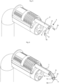
- Le chargeur (28) est placé à cheval sur l'extrémité distale d'un endoscope (29). La tige (2) est repoussée légèrement hors du manchon (1).
- L'agrafe (5) à l'extrémité frontale distale de la série d'agrafes adjacentes est repoussée par l'action de l'arceau (22) et vient se loger dans la zone de réception de la tige (2) comme représenté en
figure 3 . Les autres agrafes sont maintenues en place autour de la zone dorsale (21) du chargeur (28) par frottement. La zone de liaison (7) est placée derrière le téton (4), c'est-à-dire du côté de l'extrémité proximale (du côté de l'opérateur), alors que le téton est du côté de l'extrémité distale (du côté des tissus à maintenir). - On retire ensuite la tige (2) à l'intérieur du manchon (1) comme représenté en
figure 4 . Les branches (8, 9) s'engagent alors dans les encoches latérales prévues à l'extrémité frontale du manchon (1). L'agrafe (5) est alors coincée entre le téton (4) et la surface frontale du manchon (1), et peut être manipulé par le déplacement conjoint du manchon (1) et de la tige (2). On peut ainsi déplacer l'agrafe par une action extérieure en déplacement axial longitudinal et en rotation autour de l'axe longitudinal comme représenté enfigure 5 . Pendant le déplacement longitudinal, les pointes (10, 11) viennent affleurer les tissus, dans le champ de vision de l'endoscope, et accrochent les tissus à rapprocher. - En déplaçant ensuite le tube (2) par rapport au manchon (1), ce qui produit la déformation des deux branches (8, 9) qui viennent se replier pour venir en position parallèle, pour pincer les tissus entre les crochets (12, 13). Pendant que les branches (8, 9) sont rabattues l'une contre l'autre, les extrémités pointues (10, 11) entraînent les tissus selon une trajectoire semi-circulaire, pour les positionner entre les crochets (12, 13).
- L'utilisateur peut ensuite charger une autre agrafe sur la tige mobile en rétractant le manchon et la tige et recommencer ainsi le cycle pour la pose d'une nouvelle agrafe.
- Grâce au moyen de déplacement longitudinal de l'agrafe et à la position transversale de l'agrafe (5) une fois celle-ci chargée sur le moyen de retenue, l'applicateur peut avantageusement être disposé sur un endoscope en retrait de l'extrémité de ce dernier afin que le dispositif ne pénètre pas dans le champ de vision de l'endoscope mais que les extrémités des branches (8,9) de l'agrafe (5) pénètrent dans le champ de vision dudit endoscope.
Claims (3)
- - Système de chirurgie endoscopique formé par des agrafes présentant une zone centrale et deux branches (8, 9) et par un applicateur endoscopique d'agrafes comportant un chargeur d'agrafes (28) disposées transversalement,- l'applicateur comportant un manchon tubulaire (1) creux rigide et une tige rigide (2) coulissant longitudinalement à l'intérieur dans ce manchon (1) présentant un canal de guidage à section complémentaire,- lesdites agrafes présentant, en vue de face et avant agrafage, une forme générale semi-annulaire ou de « fer à cheval », et étant formées par deux branches arquées (8, 9) reliées par un tronçon de liaison (7) et s'étendant dans un plan transversal perpendiculaire à l'axe longitudinal du manchon (1), symétriquement par rapport à un plan médian (6) passant par le milieu dudit tronçon de liaison (7), chacune des branches arquées (8, 9) présentant une extrémité pointue (10, 11) en forme de crochet s'étendant en avant du plan transversal contenant la branche correspondante (8, 9), et un crochet (12, 13) se projetant en avant dudit plan transversal et positionné plus près de ladite extrémité pointue respectivement (10, 11) que ledit tronçon de liaison (7), lesdits crochets (12, 13) présentant une surface de pincement (14, 15) sensiblement parallèle audit plan transversal,- ladite tige (2) présentant un moyen de retenue (3) d'une agrafe à appliquer (5) disposée dans un plan transversal par rapport audit moyen de retenu (3) pour assurer sa déformation par pliage par rapport au plan médian (6) de symétrie de ladite agrafe.
- - Système de chirurgie endoscopique selon la revendication précédente caractérisé en ce que ladite tige (2) présente une section transversale polygonale complémentaire de la section dudit canal de guidage prévue dans le manchon (1).
- - Système de chirurgie endoscopique selon la revendication précédente caractérisé en ce que ledit chargeur d'agrafes (28) comporte un boîtier (20) apte à être monté sur l'extrémité distale d'un endoscope (29), et présente une partie dorsale définissant une surface de réception dont la section correspond à la section transversale définie par les bords intérieurs des deux branches d'une agrafe, le chargeur comportant en outre un arceau engagé sur cette partie dorsale et guidé par deux cannelures latérales.
Applications Claiming Priority (2)
| Application Number | Priority Date | Filing Date | Title |
|---|---|---|---|
| FR1551204A FR3032608B1 (fr) | 2015-02-13 | 2015-02-13 | Systeme de chirurgie endoscopique forme d’une part par une pluralite d’agrafes et d’autre part par un applicateur endoscopique. |
| PCT/FR2016/050330 WO2016128693A1 (fr) | 2015-02-13 | 2016-02-12 | Système de chirurgie endoscopique formé d'une part par une pluralité d'agrafes et d'autre part par un applicateur endoscopique |
Publications (3)
| Publication Number | Publication Date |
|---|---|
| EP3256056A1 EP3256056A1 (fr) | 2017-12-20 |
| EP3256056B1 true EP3256056B1 (fr) | 2024-12-04 |
| EP3256056C0 EP3256056C0 (fr) | 2024-12-04 |
Family
ID=53674025
Family Applications (1)
| Application Number | Title | Priority Date | Filing Date |
|---|---|---|---|
| EP16707917.7A Active EP3256056B1 (fr) | 2015-02-13 | 2016-02-12 | Système de chirurgie endoscopique formé d'une part par une pluralité d'agrafes et d'autre part par un applicateur endoscopique |
Country Status (6)
| Country | Link |
|---|---|
| US (1) | US11166719B2 (fr) |
| EP (1) | EP3256056B1 (fr) |
| JP (1) | JP6806691B2 (fr) |
| KR (1) | KR102548730B1 (fr) |
| FR (1) | FR3032608B1 (fr) |
| WO (1) | WO2016128693A1 (fr) |
Families Citing this family (5)
| Publication number | Priority date | Publication date | Assignee | Title |
|---|---|---|---|---|
| FR3061425B1 (fr) | 2017-01-03 | 2019-01-25 | Institut Hospitalo-Universitaire De Chirurgie Mini-Invasive Guidee Par L'image | Agrafe chirurgicale presentant deux branches mobiles reliees par une zone de liaison transversale |
| FR3100124B1 (fr) | 2019-08-30 | 2025-03-14 | Institut Hospitalo Univ De Chirurgie Mini Invasive Guidee Par Limage | Dispositif chirurgical comportant une tige présentant à son extrémité distale un manchon déformable entourant ladite tige |
| WO2021151923A1 (fr) | 2020-01-30 | 2021-08-05 | Institut Hospitalo-Universitaire De Chirurgie Mini -Invasive Guidee Par L'image | Poignée d'actionnement pour actionner un outil d'application chirurgical et outil d'application comprenant une poignée d'actionnement correspondante |
| FR3139272B1 (fr) * | 2022-09-02 | 2025-05-02 | Peters Surgical | cartouche pour agrafes chirurgicales |
| US12268385B2 (en) | 2023-05-11 | 2025-04-08 | Taurus Endoscopy SAS | Surgical staple |
Citations (1)
| Publication number | Priority date | Publication date | Assignee | Title |
|---|---|---|---|---|
| WO2002019920A1 (fr) * | 2000-09-08 | 2002-03-14 | Coleman James E | Agrafe chirurgicale |
Family Cites Families (20)
| Publication number | Priority date | Publication date | Assignee | Title |
|---|---|---|---|---|
| US4895289A (en) * | 1986-12-22 | 1990-01-23 | Ophthalmic Ventures Limited Partnership | Ophthalmic stapler |
| US5114065A (en) * | 1988-05-23 | 1992-05-19 | Technalytics, Inc. | Surgical stapler |
| JPH0647050A (ja) * | 1992-06-04 | 1994-02-22 | Olympus Optical Co Ltd | 組織縫合結紮器 |
| US5601224A (en) * | 1992-10-09 | 1997-02-11 | Ethicon, Inc. | Surgical instrument |
| US5381943A (en) | 1992-10-09 | 1995-01-17 | Ethicon, Inc. | Endoscopic surgical stapling instrument with pivotable and rotatable staple cartridge |
| US5456400A (en) * | 1993-04-22 | 1995-10-10 | United States Surgical Corporation | Apparatus and clip for fastening body tissue |
| DE60216309T2 (de) | 2001-10-24 | 2007-06-28 | Boston Scientific Ltd., St. Michael | Endoskopisches system zur applikation einer vielzahl von blutgefässklammern |
| US7896890B2 (en) * | 2005-09-02 | 2011-03-01 | Ethicon Endo-Surgery, Inc. | Method and apparatus for endoscopically performing gastric reduction surgery in a single step |
| US7473258B2 (en) * | 2007-03-08 | 2009-01-06 | Cardica, Inc. | Surgical stapler |
| US20080269803A1 (en) * | 2007-04-25 | 2008-10-30 | Medtronic Vascular, Inc. | Arteriotomy staple with primary and secondary prongs |
| US8631991B2 (en) | 2007-05-30 | 2014-01-21 | Ethicon Endo-Surgery, Inc. | Surgical instrument |
| JP5283209B2 (ja) * | 2007-11-29 | 2013-09-04 | マニー株式会社 | 医療用ステイプル |
| US9084599B2 (en) * | 2008-05-01 | 2015-07-21 | Ethicon Endo-Surgery, Inc. | Surgical stapling instrument for applying a large staple through a small delivery port and a method of using the surgical stapler to secure a tissue fold |
| US8523040B2 (en) * | 2008-05-01 | 2013-09-03 | Ethicon Endo-Surgery, Inc. | Fastener and fastener applier having selective suture attachment |
| US20090275957A1 (en) * | 2008-05-01 | 2009-11-05 | Harris Jason L | Clip and delivery assembly used in forming a tissue fold |
| WO2012145059A1 (fr) * | 2011-02-15 | 2012-10-26 | Rotation Medical, Inc. | Procédés et appareil pour fixer des matériaux de type en feuille à un tissu cible |
| US9119617B2 (en) * | 2012-03-16 | 2015-09-01 | Ethicon, Inc. | Clamping devices for dispensing surgical fasteners into soft media |
| US9572575B2 (en) * | 2012-09-25 | 2017-02-21 | Newgen Surgical, Inc. | Skin stapler with components optimized for construction with plant based materials |
| EP3013253B1 (fr) * | 2013-06-28 | 2021-01-06 | ValCare, Inc. | Dispositif de fixation d'un article à un tissu |
| US9539005B2 (en) * | 2013-11-08 | 2017-01-10 | C.R. Bard, Inc. | Surgical fastener deployment system |
-
2015
- 2015-02-13 FR FR1551204A patent/FR3032608B1/fr active Active
-
2016
- 2016-02-12 US US15/549,595 patent/US11166719B2/en active Active
- 2016-02-12 JP JP2017542890A patent/JP6806691B2/ja active Active
- 2016-02-12 WO PCT/FR2016/050330 patent/WO2016128693A1/fr not_active Ceased
- 2016-02-12 EP EP16707917.7A patent/EP3256056B1/fr active Active
- 2016-02-12 KR KR1020177025370A patent/KR102548730B1/ko active Active
Patent Citations (1)
| Publication number | Priority date | Publication date | Assignee | Title |
|---|---|---|---|---|
| WO2002019920A1 (fr) * | 2000-09-08 | 2002-03-14 | Coleman James E | Agrafe chirurgicale |
Also Published As
| Publication number | Publication date |
|---|---|
| US11166719B2 (en) | 2021-11-09 |
| JP2018504997A (ja) | 2018-02-22 |
| US20180000482A1 (en) | 2018-01-04 |
| FR3032608B1 (fr) | 2020-10-23 |
| JP6806691B2 (ja) | 2021-01-06 |
| FR3032608A1 (fr) | 2016-08-19 |
| EP3256056A1 (fr) | 2017-12-20 |
| EP3256056C0 (fr) | 2024-12-04 |
| KR102548730B1 (ko) | 2023-06-28 |
| WO2016128693A1 (fr) | 2016-08-18 |
| KR20170120621A (ko) | 2017-10-31 |
Similar Documents
| Publication | Publication Date | Title |
|---|---|---|
| EP3256056B1 (fr) | Système de chirurgie endoscopique formé d'une part par une pluralité d'agrafes et d'autre part par un applicateur endoscopique | |
| EP3256055B1 (fr) | Agrafe chirurgicale presentant deux branches mobiles reliees par une zone de liaison transversale | |
| EP1815800B1 (fr) | Instrument chirurgical de fixation de tissu mou | |
| EP2345377B1 (fr) | Dispositif pour ligaturer une structure anatomique | |
| EP1865855B1 (fr) | Systeme de mise en place de moyens formant renfort d'une suture | |
| EP0369324B1 (fr) | Instrument de chirurgie | |
| EP3071120B1 (fr) | Dispositif chirurgical multifonctionnel rechargeable et jetable | |
| WO2006037893A1 (fr) | Appareil de stockage, distribution et pose d'attaches chirurgicales | |
| FR2777443A1 (fr) | Ancillaire pour la mise en place et le retrait d'un implant et plus particulierement d'une ancre de suture | |
| US11707282B2 (en) | Multi-piece ligation clip | |
| FR2827756A1 (fr) | Lacs perfectionne et applicateurs associes utilisables en chirurgie endoscopique | |
| FR2906995A1 (fr) | Passe-fil chirurgical multi-aiguilles pour organe creux et systeme correspondant | |
| EP1778097B1 (fr) | Instrument et dispositif d'ancrage parietal notamment pour chirurgie laparoscopique ou coelioscopique | |
| EP3565485B1 (fr) | Agrafe chirurgicale presentant deux branches mobiles reliees par une zone de liaison transversale | |
| WO2018046822A1 (fr) | Porte-aiguille endoscopique | |
| EP4444192B1 (fr) | Dispositif de plicature gastrique par voie endoscopique | |
| FR3120776A1 (fr) | Système de suture endoscopique et dispositif médical utilisant ce système. | |
| FR2881042A1 (fr) | Attaches chirurgicales | |
| FR2831791A1 (fr) | Dispositif pour l'introduction et la mise en place d'un lacs notamment en chirurgie endoscopique |
Legal Events
| Date | Code | Title | Description |
|---|---|---|---|
| STAA | Information on the status of an ep patent application or granted ep patent |
Free format text: STATUS: THE INTERNATIONAL PUBLICATION HAS BEEN MADE |
|
| PUAI | Public reference made under article 153(3) epc to a published international application that has entered the european phase |
Free format text: ORIGINAL CODE: 0009012 |
|
| STAA | Information on the status of an ep patent application or granted ep patent |
Free format text: STATUS: REQUEST FOR EXAMINATION WAS MADE |
|
| 17P | Request for examination filed |
Effective date: 20170811 |
|
| AK | Designated contracting states |
Kind code of ref document: A1 Designated state(s): AL AT BE BG CH CY CZ DE DK EE ES FI FR GB GR HR HU IE IS IT LI LT LU LV MC MK MT NL NO PL PT RO RS SE SI SK SM TR |
|
| AX | Request for extension of the european patent |
Extension state: BA ME |
|
| DAV | Request for validation of the european patent (deleted) | ||
| DAX | Request for extension of the european patent (deleted) | ||
| STAA | Information on the status of an ep patent application or granted ep patent |
Free format text: STATUS: EXAMINATION IS IN PROGRESS |
|
| 17Q | First examination report despatched |
Effective date: 20190918 |
|
| RAP1 | Party data changed (applicant data changed or rights of an application transferred) |
Owner name: TAURUS ENDOSCOPY |
|
| GRAP | Despatch of communication of intention to grant a patent |
Free format text: ORIGINAL CODE: EPIDOSNIGR1 |
|
| STAA | Information on the status of an ep patent application or granted ep patent |
Free format text: STATUS: GRANT OF PATENT IS INTENDED |
|
| INTG | Intention to grant announced |
Effective date: 20240626 |
|
| GRAS | Grant fee paid |
Free format text: ORIGINAL CODE: EPIDOSNIGR3 |
|
| GRAA | (expected) grant |
Free format text: ORIGINAL CODE: 0009210 |
|
| STAA | Information on the status of an ep patent application or granted ep patent |
Free format text: STATUS: THE PATENT HAS BEEN GRANTED |
|
| AK | Designated contracting states |
Kind code of ref document: B1 Designated state(s): AL AT BE BG CH CY CZ DE DK EE ES FI FR GB GR HR HU IE IS IT LI LT LU LV MC MK MT NL NO PL PT RO RS SE SI SK SM TR |
|
| REG | Reference to a national code |
Ref country code: GB Ref legal event code: FG4D Free format text: NOT ENGLISH |
|
| REG | Reference to a national code |
Ref country code: CH Ref legal event code: EP |
|
| REG | Reference to a national code |
Ref country code: DE Ref legal event code: R096 Ref document number: 602016090488 Country of ref document: DE |
|
| REG | Reference to a national code |
Ref country code: IE Ref legal event code: FG4D Free format text: LANGUAGE OF EP DOCUMENT: FRENCH |
|
| U01 | Request for unitary effect filed |
Effective date: 20241226 |
|
| U07 | Unitary effect registered |
Designated state(s): AT BE BG DE DK EE FI FR IT LT LU LV MT NL PT RO SE SI Effective date: 20250114 |
|
| U20 | Renewal fee for the european patent with unitary effect paid |
Year of fee payment: 10 Effective date: 20250121 |
|
| PG25 | Lapsed in a contracting state [announced via postgrant information from national office to epo] |
Ref country code: HR Free format text: LAPSE BECAUSE OF FAILURE TO SUBMIT A TRANSLATION OF THE DESCRIPTION OR TO PAY THE FEE WITHIN THE PRESCRIBED TIME-LIMIT Effective date: 20241204 |
|
| PG25 | Lapsed in a contracting state [announced via postgrant information from national office to epo] |
Ref country code: ES Free format text: LAPSE BECAUSE OF FAILURE TO SUBMIT A TRANSLATION OF THE DESCRIPTION OR TO PAY THE FEE WITHIN THE PRESCRIBED TIME-LIMIT Effective date: 20241204 |
|
| PG25 | Lapsed in a contracting state [announced via postgrant information from national office to epo] |
Ref country code: NO Free format text: LAPSE BECAUSE OF FAILURE TO SUBMIT A TRANSLATION OF THE DESCRIPTION OR TO PAY THE FEE WITHIN THE PRESCRIBED TIME-LIMIT Effective date: 20250304 |
|
| PG25 | Lapsed in a contracting state [announced via postgrant information from national office to epo] |
Ref country code: GR Free format text: LAPSE BECAUSE OF FAILURE TO SUBMIT A TRANSLATION OF THE DESCRIPTION OR TO PAY THE FEE WITHIN THE PRESCRIBED TIME-LIMIT Effective date: 20250305 |
|
| PG25 | Lapsed in a contracting state [announced via postgrant information from national office to epo] |
Ref country code: RS Free format text: LAPSE BECAUSE OF FAILURE TO SUBMIT A TRANSLATION OF THE DESCRIPTION OR TO PAY THE FEE WITHIN THE PRESCRIBED TIME-LIMIT Effective date: 20250304 |
|
| PG25 | Lapsed in a contracting state [announced via postgrant information from national office to epo] |
Ref country code: SM Free format text: LAPSE BECAUSE OF FAILURE TO SUBMIT A TRANSLATION OF THE DESCRIPTION OR TO PAY THE FEE WITHIN THE PRESCRIBED TIME-LIMIT Effective date: 20241204 |
|
| PG25 | Lapsed in a contracting state [announced via postgrant information from national office to epo] |
Ref country code: PL Free format text: LAPSE BECAUSE OF FAILURE TO SUBMIT A TRANSLATION OF THE DESCRIPTION OR TO PAY THE FEE WITHIN THE PRESCRIBED TIME-LIMIT Effective date: 20241204 |
|
| PG25 | Lapsed in a contracting state [announced via postgrant information from national office to epo] |
Ref country code: IS Free format text: LAPSE BECAUSE OF FAILURE TO SUBMIT A TRANSLATION OF THE DESCRIPTION OR TO PAY THE FEE WITHIN THE PRESCRIBED TIME-LIMIT Effective date: 20250404 |
|
| PG25 | Lapsed in a contracting state [announced via postgrant information from national office to epo] |
Ref country code: SK Free format text: LAPSE BECAUSE OF FAILURE TO SUBMIT A TRANSLATION OF THE DESCRIPTION OR TO PAY THE FEE WITHIN THE PRESCRIBED TIME-LIMIT Effective date: 20241204 |
|
| PG25 | Lapsed in a contracting state [announced via postgrant information from national office to epo] |
Ref country code: CZ Free format text: LAPSE BECAUSE OF FAILURE TO SUBMIT A TRANSLATION OF THE DESCRIPTION OR TO PAY THE FEE WITHIN THE PRESCRIBED TIME-LIMIT Effective date: 20241204 |
|
| PG25 | Lapsed in a contracting state [announced via postgrant information from national office to epo] |
Ref country code: MC Free format text: LAPSE BECAUSE OF FAILURE TO SUBMIT A TRANSLATION OF THE DESCRIPTION OR TO PAY THE FEE WITHIN THE PRESCRIBED TIME-LIMIT Effective date: 20241204 |
|
| REG | Reference to a national code |
Ref country code: CH Ref legal event code: PL |
|
| PLBE | No opposition filed within time limit |
Free format text: ORIGINAL CODE: 0009261 |
|
| STAA | Information on the status of an ep patent application or granted ep patent |
Free format text: STATUS: NO OPPOSITION FILED WITHIN TIME LIMIT |
|
| PG25 | Lapsed in a contracting state [announced via postgrant information from national office to epo] |
Ref country code: CH Free format text: LAPSE BECAUSE OF NON-PAYMENT OF DUE FEES Effective date: 20250228 |
|
| 26N | No opposition filed |
Effective date: 20250905 |
|
| PG25 | Lapsed in a contracting state [announced via postgrant information from national office to epo] |
Ref country code: IE Free format text: LAPSE BECAUSE OF NON-PAYMENT OF DUE FEES Effective date: 20250212 |
|
| U20 | Renewal fee for the european patent with unitary effect paid |
Year of fee payment: 11 Effective date: 20260121 |
|
| PGFP | Annual fee paid to national office [announced via postgrant information from national office to epo] |
Ref country code: GB Payment date: 20260121 Year of fee payment: 11 |