EP3256278B1 - Dispositif de coulée pour couler un métal fondu et procédé pour faire fonctionner un tel dispositif de coulée - Google Patents
Dispositif de coulée pour couler un métal fondu et procédé pour faire fonctionner un tel dispositif de coulée Download PDFInfo
- Publication number
- EP3256278B1 EP3256278B1 EP16703800.9A EP16703800A EP3256278B1 EP 3256278 B1 EP3256278 B1 EP 3256278B1 EP 16703800 A EP16703800 A EP 16703800A EP 3256278 B1 EP3256278 B1 EP 3256278B1
- Authority
- EP
- European Patent Office
- Prior art keywords
- pouring
- casting
- rings
- ladle
- casting ladle
- Prior art date
- Legal status (The legal status is an assumption and is not a legal conclusion. Google has not performed a legal analysis and makes no representation as to the accuracy of the status listed.)
- Not-in-force
Links
- 238000000034 method Methods 0.000 title claims description 9
- 239000002184 metal Substances 0.000 title claims 2
- 229910052751 metal Inorganic materials 0.000 title claims 2
- 238000005266 casting Methods 0.000 claims description 31
- 239000000155 melt Substances 0.000 claims description 11
- 238000007789 sealing Methods 0.000 claims description 7
- 238000001816 cooling Methods 0.000 claims description 6
- XEEYBQQBJWHFJM-UHFFFAOYSA-N Iron Chemical compound [Fe] XEEYBQQBJWHFJM-UHFFFAOYSA-N 0.000 claims description 4
- 229910010293 ceramic material Inorganic materials 0.000 claims description 3
- 239000007788 liquid Substances 0.000 claims description 3
- 229910052742 iron Inorganic materials 0.000 claims description 2
- 239000000919 ceramic Substances 0.000 description 2
- 238000012544 monitoring process Methods 0.000 description 2
- 238000010276 construction Methods 0.000 description 1
- 238000011161 development Methods 0.000 description 1
- 238000007599 discharging Methods 0.000 description 1
- 238000005516 engineering process Methods 0.000 description 1
- 238000002844 melting Methods 0.000 description 1
- 230000008018 melting Effects 0.000 description 1
- 229930194120 perseal Natural products 0.000 description 1
- 238000003825 pressing Methods 0.000 description 1
- 239000004575 stone Substances 0.000 description 1
- 238000012546 transfer Methods 0.000 description 1
Images



Classifications
-
- B—PERFORMING OPERATIONS; TRANSPORTING
- B22—CASTING; POWDER METALLURGY
- B22D—CASTING OF METALS; CASTING OF OTHER SUBSTANCES BY THE SAME PROCESSES OR DEVICES
- B22D35/00—Equipment for conveying molten metal into beds or moulds
- B22D35/04—Equipment for conveying molten metal into beds or moulds into moulds, e.g. base plates, runners
-
- B—PERFORMING OPERATIONS; TRANSPORTING
- B22—CASTING; POWDER METALLURGY
- B22D—CASTING OF METALS; CASTING OF OTHER SUBSTANCES BY THE SAME PROCESSES OR DEVICES
- B22D39/00—Equipment for supplying molten metal in rations
- B22D39/06—Equipment for supplying molten metal in rations having means for controlling the amount of molten metal by controlling the pressure above the molten metal
-
- B—PERFORMING OPERATIONS; TRANSPORTING
- B22—CASTING; POWDER METALLURGY
- B22D—CASTING OF METALS; CASTING OF OTHER SUBSTANCES BY THE SAME PROCESSES OR DEVICES
- B22D41/00—Casting melt-holding vessels, e.g. ladles, tundishes, cups or the like
-
- B—PERFORMING OPERATIONS; TRANSPORTING
- B22—CASTING; POWDER METALLURGY
- B22D—CASTING OF METALS; CASTING OF OTHER SUBSTANCES BY THE SAME PROCESSES OR DEVICES
- B22D47/00—Casting plants
Definitions
- the invention relates to a device for pouring off individual molds with a metallic melt, in particular liquid iron, with a stationary pouring ladle having a lid, a sprue and a spout, to which the molds are fed via a conveyor along a pouring path, the spout being the pouring ladle has at least two pouring nozzles and a method for operating such a pouring device.
- Casting devices have long been known in the most varied of designs from practice.
- a pouring ladle is filled with a metallic melt, which is tilted or swiveled during pouring, so that the melt is poured into a mold to be poured via a pouring spout. Due to the large masses, only small and medium-sized pans are tilted or swiveled when pouring. Large pans, on the other hand, are usually emptied by pulling a stopper.
- pouring ladles with several pouring openings - mostly in the form of a double pouring spout - have already been developed in order to achieve a simultaneous pouring of several forms.
- the US-A-3,058,180 shows a casting device of the generic type. There, the pouring ladle also has several pouring spouts if several casting molds have to be poured at the same time. Said device offers however, not the possibility of compensating for differences in the distance between mold openings.
- the invention is based on the object of designing and developing the above-mentioned device for casting individual molds with a metallic melt in such a way that it can be used as universally as possible to achieve high casting performance.
- the at least one pivotable pouring spout is rotatably arranged on the pouring ladle by means of a firmly connected riser pipe.
- the riser pipe can be flanged to the pouring spout, but it is also possible to provide part of the riser pipe in a corresponding opening in the pouring spout.
- Such an opening and the corresponding shape of the pouring pipe can be cylindrical or conical.
- Each riser pipe is preferably made of ceramic material in order to control the temperatures of the liquid melt inside the pouring ladle.
- the pouring ladle has a forehearth on which the pouring spouts are mounted. In this way the lid of the ladle remains freely accessible.
- the at least one pivotable pouring spout may be arranged in the lid of the pouring ladle itself.
- the pouring ladle has two pivotable pouring nozzles. This is particularly useful because, when the distance between the two pouring points is adjusted, both pouring nozzles can be pivoted towards or away from one another at the same time in order to be able to carry out the pivoting process in the shortest possible time.
- each pouring spout has a pouring opening (so-called nozzle block) that can be closed by means of a stopper above the pouring section. This allows very precise dosing when pouring.
- the pouring ladle has an inductor for keeping the melt warm and possibly circulating it, which is preferably arranged at the bottom of the pouring ladle.
- each rotatable riser pipe for sealing to the fixed cover of the forehearth or the pouring ladle has a seal which comprises a plurality of O-rings arranged one above the other and / or concentrically.
- O-rings There is preferably a plurality of O-rings arranged one above the other and an annular channel is formed between at least two O-rings, which at least can be acted upon by compressed air via a line.
- Packets” of O-rings can be compressed to such an extent by the application of pressure that an optimal seal of the lid / riser pipe joint is guaranteed.
- a further embodiment of the invention provides that there is a plurality of O-rings arranged one above the other and that an annular channel is formed between at least two O-rings, to which compressed air can be applied via at least one line.
- At least one annular space for cooling the seal is provided between the riser pipe and the O-rings.
- O-rings used are designed as thermal seals in order to withstand the stresses caused by the high ambient temperatures.
- the O-rings arranged one above the other can be pressed onto one another by means of a mechanical tensioning device, such as a tension ring.
- a mechanical tensioning device such as a tension ring.
- Such a configuration can, so to speak, serve as an “abutment” on one side of the O-rings arranged one above the other when the seals are pressed together from the other side by the compressed air of the ring channel.
- the mechanical tensioning device exerts even pressure on the top and / or bottom sealing surface of the O-rings used so that an optimal seal is reliably guaranteed.
- a method for operating a device according to one of claims 1 to 10 achieves the aforementioned object of the present invention in that the pouring takes place automatically.
- the method for operating a device according to claim 10 or 11 is carried out in such a way that the annular channel and / or the annular space can / can be actively cooled.
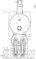
- a pouring ladle 1 with a closed lid 2 initially has a sprue 3 and, instead of a spout, in the preferred case a forehearth 4 on which - in the illustrated case - two pouring nozzles 5 can be pivoted about a vertical axis A (only in FIG Fig. 2 shown) and are each in contact via a flange-mounted riser 6 with a melt 7 located in the interior of the pouring ladle 1.
- the melt 7 may only be emptied up to a sump line 8 so that no gas can get into the riser 6.
- this can be guaranteed by precise monitoring of the furnace pressure. Alternatively or additionally, this can be guaranteed by monitoring the weight of the oven and its contents.
- the pouring ladle 1 is filled almost up to the upper edge of the forehearth 4 and the respective melting level 9 is correspondingly drawn both in the interior of the pouring ladle 1 and in the pouring spout 5.
- the volumes of the molds F are relatively small in relation to the pouring nozzles 5 and so in the example shown, only every second mold F is filled at the same time with one casting process, which also has advantages in terms of casting technology.
- the pouring nozzles 5 can be pivoted towards or away from each other, so that the distance between the two pouring points can be adjusted from a - structurally predetermined - minimum value to a maximum value.
- the position of the pouring spouts 5 can be adjusted or readjusted while the molds F are being advanced. For this purpose, only the distance between the two openings 0 to be filled needs to be detected, which can already take place on the casting line before reaching the casting station.
- the pouring ladle 1 also has an inductor 12 on its underside so that the melt 7 contained in it can be kept at the desired temperature.
- a channel inductor is preferably used for this purpose, so that circulation of the melt is also possible in this way.
- O-rings 14 and 15 designed as thermal seals, of which five seals 14 with identical dimensions are arranged one above the other and the two lowest O-rings 15 are arranged concentrically inside one another per seal 13. Due to the pressurization of the interior of the pouring ladle 1, the seal 13 must be made pressure-tight. For this purpose, a counter pressure must be built up on the seals 14, 15. It can be seen that for this purpose, between the lower three O-rings 14 and the two O-rings arranged above 14 an annular channel 16 runs. This can be connected via lines 17 and 18 to a source of compressed air or another gas under pressure. Although a single pressure line would be sufficient to act on the annular channel 16, the embodiment shown has the advantage that compressed air or the like can be supplied and discharged at the same time. This can be done quantified through the use of suitable throttle devices.
- annular space 19 for cooling the seal 13 is provided between each riser pipe 6 and the O-rings 14, which (with corresponding unspecified walls) inwards from the riser pipe 6 and after is limited on the outside by the O-ring packets 14 or the ring channel 16.
- the annular space 19 By connecting the annular space 19 to the annular channel 16, active and very effective cooling of each seal 13 can be achieved.
- the O-ring packs 14 can be compressed even further from above by means of an adjustable clamping ring 20 in order to improve their sealing effect.
- Figures 4 and 5 yet another embodiment of the invention.
- analogous representation shows a pouring ladle 1 'with a lid 2' and a sprue 3 ', with the two pouring nozzles 5' pivotable about a vertical axis A (only in Fig. 5 shown) are rotatably attached to the cover 2 'of the pouring ladle 1' and each via a flange-mounted riser pipe 6 'with a melt 7 located inside the pouring ladle 1 as before Fig. 1 are in contact.
Landscapes
- Engineering & Computer Science (AREA)
- Mechanical Engineering (AREA)
- Casting Support Devices, Ladles, And Melt Control Thereby (AREA)
Claims (17)
- Dispositif de remplissage de différents moules avec une masse fondue métallique (7), en particulier avec du fer liquide, ledit remplissage étant effectué avec une poche de coulée (1, 1') disposée en étant stationnaire et présentant un couvercle (2, 2'), une descente de coulée (3, 3') et une busette de coulée, dispositif auquel sont amenés les moules (F), par un convoyeur (C), le long d'une ligne de coulée, où la busette de coulée de la poche de coulée (1, 1') présente au moins deux becs de coulée (5, 5'),
caractérisé en ce qu'au moins un bec de coulée (5, 5') est disposé en pouvant pivoter autour d'un axe vertical (A), de manière telle que la distance des points de coulée puisse être variable. - Dispositif selon la revendication 1,
caractérisé
en ce que le bec de coulée (5, 5') au moins au nombre de un, qui peut pivoter, est disposé en pouvant tourner sur la poche de coulée (1, 1') au moyen d'un tuyau de montée (6, 6') solidement assemblé. - Dispositif selon la revendication 2,
caractérisé en ce que
chaque tuyau de montée (6, 6') se compose d'un matériau en céramique. - Dispositif selon l'une quelconque des revendications 1 à 3,
caractérisé en ce que
la poche de coulée (1) présente un avant creuset (4) et en ce que les becs de coulée (5) sont montés sur l'avant-creuset (4). - Dispositif selon l'une quelconque des revendications 1 à 3,
caractérisé en ce que
le bec de coulée (5') au moins au nombre de un, qui peut pivoter, est disposé dans le couvercle (2') de la poche de coulée (1'). - Dispositif selon l'une quelconque des revendications 1 à 5,
caractérisé en ce que
la poche de coulée (1, 1') présente deux becs de coulée (5, 5') qui peuvent pivoter. - Dispositif selon l'une quelconque des revendications 1 à 6,
caractérisé en ce que
chaque bec de coulée (5, 5') présente, au dessus de la ligne de coulée, une ouverture de coulée (10) pouvant être fermée au moyen d'un bouchon (9). - Dispositif selon l'une quelconque des revendications 1 à 7,
caractérisé en ce que
la poche de coulée (1, 1') présente un inducteur, ledit inducteur servant au maintien à température et, le cas échéant, à la circulation de la masse fondue. - Dispositif selon l'une quelconque des revendications 2 à 8,
caractérisé en ce que
chaque tuyau de montée (6, 6'), qui peut tourner, présente un joint d'étanchéité (13) prévu pour assurer l'étanchéité par rapport au couvercle fixe (2, 2') de l'avant-creuset (4) ou de la poche de coulée (1'), lequel joint d'étanchéité comprend une pluralité de joints toriques disposés en étant superposés les uns aux autres et/ou disposés de façon concentrique. - Dispositif selon la revendication 9,
caractérisé
en ce qu'une pluralité de joints toriques (14) disposés en étant superposés les uns aux autres est fournie, et en ce qu'un canal annulaire (16) est formé entre au moins deux joints toriques (14), lequel canal annulaire peut être alimenté en air comprimé par au moins une conduite (17, 18). - Dispositif selon la revendication 10,
caractérisé
en ce qu'il est prévu au moins un espace annulaire (19) servant au refroidissement du joint d'étanchéité (13), ledit espace annulaire étant placé entre le tuyau de montée (6) et des joints toriques (14). - Dispositif selon la revendication 11,
caractérisé en ce que
l'espace annulaire (19) est relié au canal annulaire (16). - Dispositif selon la revendication 9 ou 11,
caractérisé en ce que
la totalité des joints toriques ou bien quelques-uns d'entre aux sont conçus comme des joints d'isolation thermique. - Dispositif selon l'une quelconque des revendications 9 à 11,
caractérisé en ce que
les joints toriques (14) disposés en étant superposés les uns aux autres peuvent être pressés les uns contre les autres au moyen d'un dispositif de serrage mécanique (20). - Procédé pour faire fonctionner un dispositif selon l'une quelconque des revendications 1 à 14,
caractérisé en ce que
le remplissage se produit de manière automatisée. - Procédé selon la revendication 15,
caractérisé en ce que
le remplissage se produit par mise sous pression de la masse fondue (7) se trouvant dans la poche de coulée (1, 1'). - Procédé selon la revendication 10 ou 11,
caractérisé en ce que
le canal annulaire (16) et/ou l'espace annulaire (19) peut / peuvent être refroidi(s) activement.
Applications Claiming Priority (2)
| Application Number | Priority Date | Filing Date | Title |
|---|---|---|---|
| DE102015101901.9A DE102015101901B4 (de) | 2015-02-10 | 2015-02-10 | Gießvorrichtung zum Abgießen einer metallischen Schmelze |
| PCT/EP2016/052850 WO2016128481A1 (fr) | 2015-02-10 | 2016-02-10 | Dispositif de coulée pour couler un métal fondu et procédé pour faire fonctionner un tel dispositif de coulée |
Publications (2)
| Publication Number | Publication Date |
|---|---|
| EP3256278A1 EP3256278A1 (fr) | 2017-12-20 |
| EP3256278B1 true EP3256278B1 (fr) | 2020-09-02 |
Family
ID=55345831
Family Applications (1)
| Application Number | Title | Priority Date | Filing Date |
|---|---|---|---|
| EP16703800.9A Not-in-force EP3256278B1 (fr) | 2015-02-10 | 2016-02-10 | Dispositif de coulée pour couler un métal fondu et procédé pour faire fonctionner un tel dispositif de coulée |
Country Status (3)
| Country | Link |
|---|---|
| EP (1) | EP3256278B1 (fr) |
| DE (1) | DE102015101901B4 (fr) |
| WO (1) | WO2016128481A1 (fr) |
Families Citing this family (2)
| Publication number | Priority date | Publication date | Assignee | Title |
|---|---|---|---|---|
| DE102018106078B4 (de) | 2018-03-15 | 2019-10-31 | EKW Gesellschaft mit beschränkter Haftung | Ausgussstein |
| CN112756591A (zh) * | 2020-12-25 | 2021-05-07 | 安徽应流集团霍山铸造有限公司 | 一种解决铸件浇注过程中金属液吸气和氧化的装置 |
Family Cites Families (12)
| Publication number | Priority date | Publication date | Assignee | Title |
|---|---|---|---|---|
| DE742183C (de) * | 1940-12-03 | 1943-11-24 | Eduard Scholle | Kippbares Giessgefaess fuer Metall |
| GB626795A (en) * | 1947-06-04 | 1949-07-21 | H J Enthoven & Sons Ltd | Means for effecting intermittent automatic delivery of liquid derived from a bulk supply |
| US3058180A (en) * | 1961-10-11 | 1962-10-16 | Modern Equipment Co | Apparatus for pouring molten metal |
| US3631915A (en) * | 1969-12-29 | 1972-01-04 | Arthur L Perry | Metal-pouring apparatus for a smelting furnace |
| DE7246692U (de) * | 1972-04-26 | 1973-04-05 | Regie Nationale Des Usines Renault Boulogne Billancourt | Doppelgießpfanne für geschmolzene Metalle oder Metallegierungen |
| SE401989B (sv) * | 1974-11-11 | 1978-06-12 | Asea Ab | Anordning for dosering av smelta, exempelvis jern- eller stalsmelta fran en trycktappnigsugn |
| JPS55153664A (en) * | 1979-05-15 | 1980-11-29 | Toyota Motor Corp | Sprue searching device of automatic pouring machine for casting |
| US5465777A (en) * | 1994-05-18 | 1995-11-14 | The Budd Company | Contact pouring |
| DE19821946A1 (de) | 1998-05-15 | 1999-11-18 | Friedhelm Kahn | Verfahren und Vorrichtungen zum automatischen Gießen von Bauteilen durch quantifiziertes Füllen eines Raumes mit geschmolzenem Metall |
| JP4503743B2 (ja) * | 1999-10-22 | 2010-07-14 | 助川電気工業株式会社 | 溶融金属供給装置 |
| US6896032B1 (en) * | 2002-09-26 | 2005-05-24 | Hayes Lemmerz International, Inc. | Stopper-poured molten metal casting vessel with constant head height |
| US20060191660A1 (en) | 2003-06-14 | 2006-08-31 | Künkel-Wagner SLS Swisspour AG | Casting machine |
-
2015
- 2015-02-10 DE DE102015101901.9A patent/DE102015101901B4/de not_active Expired - Fee Related
-
2016
- 2016-02-10 WO PCT/EP2016/052850 patent/WO2016128481A1/fr not_active Ceased
- 2016-02-10 EP EP16703800.9A patent/EP3256278B1/fr not_active Not-in-force
Non-Patent Citations (1)
| Title |
|---|
| None * |
Also Published As
| Publication number | Publication date |
|---|---|
| DE102015101901A1 (de) | 2016-08-11 |
| DE102015101901B4 (de) | 2017-03-09 |
| EP3256278A1 (fr) | 2017-12-20 |
| WO2016128481A1 (fr) | 2016-08-18 |
Similar Documents
| Publication | Publication Date | Title |
|---|---|---|
| DE2227501C3 (de) | Gleitschieberverschluß für die Ausgußöffnung an Gießpfannen | |
| DE1299804B (de) | Bodenschieber fuer eine Giesspfanne | |
| DE102007024028A1 (de) | Vorrichtung zum Giessen von Verzehrprodukten | |
| EP2127780B1 (fr) | Système d'étanchéité d'une tête de fausse barre dans une coquille d'une installation de coulée continue pour couler des ébauches de profilés de grand format | |
| EP2572588B1 (fr) | Dispositif et procédé de répartition de masses pouvant s'écouler ou couler, notamment du chocolat aéré | |
| DE2902096C2 (fr) | ||
| DE2811055C3 (de) | Einrichtung zum Füllen einer Gießform mit Metallschmelze | |
| DE2355015A1 (de) | Giessvorrichtung mit horizontaler gleitkokille | |
| WO2009089843A1 (fr) | Système de coulée continue, en particulier de produits allongés en acier, et procédé de coulée continue | |
| EP3200941B1 (fr) | Dispositif et procédé d'ouverture d'un canal de coulée de cuves métallurgiques | |
| DE102015101901B4 (de) | Gießvorrichtung zum Abgießen einer metallischen Schmelze | |
| AT404443B (de) | Stranggiesskokille | |
| DE3319009A1 (de) | Ventil fuer einen geschmolzenes material enthaltenden behaelter | |
| DE1508560B2 (de) | Verfahren und orrichtung zum Entleeren von Schmelz- oder Warmhalteöfen | |
| DE2362702C3 (de) | Vorrichtung zum Zuführen, Fördern und Dosieren einer Metallschmelze zu einer Stranggießkokille | |
| WO2015185585A1 (fr) | Creuset segmenté | |
| EP3511090B1 (fr) | Machine de coulée sous pression à chambre froide | |
| DE102007057816A1 (de) | Filtrationseinrichtung | |
| DE69607354T2 (de) | Ventil zur durchflussregelung eines fluids, welches fette teilchen enthält | |
| EP0080997B1 (fr) | Dispositif pour la coulée continue de métaux | |
| DE102008005727B3 (de) | Zuführeinrichtung für eine Metallschmelze und eine mit einer solchen Vorrichtung ausgestattete Bandgießeinrichtung | |
| EP1897636B2 (fr) | Installation et procédé de coulée continue | |
| DE19617420C1 (de) | Zweiwalzen-Stranggießvorrichtung und Verfahren zu ihrem Betrieb | |
| DE19813806C2 (de) | Vorrichtung zur mechanischen Aufgabe von Gießpulver bei Brammenstranggussanlagen | |
| DE2929613A1 (de) | Einrichtung an einer stranggiessanlage |
Legal Events
| Date | Code | Title | Description |
|---|---|---|---|
| STAA | Information on the status of an ep patent application or granted ep patent |
Free format text: STATUS: THE INTERNATIONAL PUBLICATION HAS BEEN MADE |
|
| PUAI | Public reference made under article 153(3) epc to a published international application that has entered the european phase |
Free format text: ORIGINAL CODE: 0009012 |
|
| STAA | Information on the status of an ep patent application or granted ep patent |
Free format text: STATUS: REQUEST FOR EXAMINATION WAS MADE |
|
| 17P | Request for examination filed |
Effective date: 20170704 |
|
| AK | Designated contracting states |
Kind code of ref document: A1 Designated state(s): AL AT BE BG CH CY CZ DE DK EE ES FI FR GB GR HR HU IE IS IT LI LT LU LV MC MK MT NL NO PL PT RO RS SE SI SK SM TR |
|
| AX | Request for extension of the european patent |
Extension state: BA ME |
|
| DAV | Request for validation of the european patent (deleted) | ||
| DAX | Request for extension of the european patent (deleted) | ||
| STAA | Information on the status of an ep patent application or granted ep patent |
Free format text: STATUS: EXAMINATION IS IN PROGRESS |
|
| 17Q | First examination report despatched |
Effective date: 20180920 |
|
| GRAP | Despatch of communication of intention to grant a patent |
Free format text: ORIGINAL CODE: EPIDOSNIGR1 |
|
| STAA | Information on the status of an ep patent application or granted ep patent |
Free format text: STATUS: GRANT OF PATENT IS INTENDED |
|
| INTG | Intention to grant announced |
Effective date: 20200420 |
|
| GRAS | Grant fee paid |
Free format text: ORIGINAL CODE: EPIDOSNIGR3 |
|
| GRAA | (expected) grant |
Free format text: ORIGINAL CODE: 0009210 |
|
| STAA | Information on the status of an ep patent application or granted ep patent |
Free format text: STATUS: THE PATENT HAS BEEN GRANTED |
|
| AK | Designated contracting states |
Kind code of ref document: B1 Designated state(s): AL AT BE BG CH CY CZ DE DK EE ES FI FR GB GR HR HU IE IS IT LI LT LU LV MC MK MT NL NO PL PT RO RS SE SI SK SM TR |
|
| REG | Reference to a national code |
Ref country code: GB Ref legal event code: FG4D Free format text: NOT ENGLISH |
|
| REG | Reference to a national code |
Ref country code: AT Ref legal event code: REF Ref document number: 1308254 Country of ref document: AT Kind code of ref document: T Effective date: 20200915 Ref country code: CH Ref legal event code: EP |
|
| REG | Reference to a national code |
Ref country code: DE Ref legal event code: R096 Ref document number: 502016011013 Country of ref document: DE |
|
| REG | Reference to a national code |
Ref country code: IE Ref legal event code: FG4D Free format text: LANGUAGE OF EP DOCUMENT: GERMAN |
|
| REG | Reference to a national code |
Ref country code: DK Ref legal event code: T3 Effective date: 20200929 |
|
| REG | Reference to a national code |
Ref country code: LT Ref legal event code: MG4D |
|
| PG25 | Lapsed in a contracting state [announced via postgrant information from national office to epo] |
Ref country code: FI Free format text: LAPSE BECAUSE OF FAILURE TO SUBMIT A TRANSLATION OF THE DESCRIPTION OR TO PAY THE FEE WITHIN THE PRESCRIBED TIME-LIMIT Effective date: 20200902 Ref country code: GR Free format text: LAPSE BECAUSE OF FAILURE TO SUBMIT A TRANSLATION OF THE DESCRIPTION OR TO PAY THE FEE WITHIN THE PRESCRIBED TIME-LIMIT Effective date: 20201203 Ref country code: SE Free format text: LAPSE BECAUSE OF FAILURE TO SUBMIT A TRANSLATION OF THE DESCRIPTION OR TO PAY THE FEE WITHIN THE PRESCRIBED TIME-LIMIT Effective date: 20200902 Ref country code: NO Free format text: LAPSE BECAUSE OF FAILURE TO SUBMIT A TRANSLATION OF THE DESCRIPTION OR TO PAY THE FEE WITHIN THE PRESCRIBED TIME-LIMIT Effective date: 20201202 Ref country code: LT Free format text: LAPSE BECAUSE OF FAILURE TO SUBMIT A TRANSLATION OF THE DESCRIPTION OR TO PAY THE FEE WITHIN THE PRESCRIBED TIME-LIMIT Effective date: 20200902 Ref country code: BG Free format text: LAPSE BECAUSE OF FAILURE TO SUBMIT A TRANSLATION OF THE DESCRIPTION OR TO PAY THE FEE WITHIN THE PRESCRIBED TIME-LIMIT Effective date: 20201202 Ref country code: HR Free format text: LAPSE BECAUSE OF FAILURE TO SUBMIT A TRANSLATION OF THE DESCRIPTION OR TO PAY THE FEE WITHIN THE PRESCRIBED TIME-LIMIT Effective date: 20200902 |
|
| REG | Reference to a national code |
Ref country code: NL Ref legal event code: MP Effective date: 20200902 |
|
| PG25 | Lapsed in a contracting state [announced via postgrant information from national office to epo] |
Ref country code: RS Free format text: LAPSE BECAUSE OF FAILURE TO SUBMIT A TRANSLATION OF THE DESCRIPTION OR TO PAY THE FEE WITHIN THE PRESCRIBED TIME-LIMIT Effective date: 20200902 Ref country code: LV Free format text: LAPSE BECAUSE OF FAILURE TO SUBMIT A TRANSLATION OF THE DESCRIPTION OR TO PAY THE FEE WITHIN THE PRESCRIBED TIME-LIMIT Effective date: 20200902 Ref country code: PL Free format text: LAPSE BECAUSE OF FAILURE TO SUBMIT A TRANSLATION OF THE DESCRIPTION OR TO PAY THE FEE WITHIN THE PRESCRIBED TIME-LIMIT Effective date: 20200902 |
|
| PG25 | Lapsed in a contracting state [announced via postgrant information from national office to epo] |
Ref country code: CZ Free format text: LAPSE BECAUSE OF FAILURE TO SUBMIT A TRANSLATION OF THE DESCRIPTION OR TO PAY THE FEE WITHIN THE PRESCRIBED TIME-LIMIT Effective date: 20200902 Ref country code: SM Free format text: LAPSE BECAUSE OF FAILURE TO SUBMIT A TRANSLATION OF THE DESCRIPTION OR TO PAY THE FEE WITHIN THE PRESCRIBED TIME-LIMIT Effective date: 20200902 Ref country code: PT Free format text: LAPSE BECAUSE OF FAILURE TO SUBMIT A TRANSLATION OF THE DESCRIPTION OR TO PAY THE FEE WITHIN THE PRESCRIBED TIME-LIMIT Effective date: 20210104 Ref country code: RO Free format text: LAPSE BECAUSE OF FAILURE TO SUBMIT A TRANSLATION OF THE DESCRIPTION OR TO PAY THE FEE WITHIN THE PRESCRIBED TIME-LIMIT Effective date: 20200902 Ref country code: EE Free format text: LAPSE BECAUSE OF FAILURE TO SUBMIT A TRANSLATION OF THE DESCRIPTION OR TO PAY THE FEE WITHIN THE PRESCRIBED TIME-LIMIT Effective date: 20200902 |
|
| PGFP | Annual fee paid to national office [announced via postgrant information from national office to epo] |
Ref country code: IT Payment date: 20210219 Year of fee payment: 6 |
|
| PG25 | Lapsed in a contracting state [announced via postgrant information from national office to epo] |
Ref country code: AL Free format text: LAPSE BECAUSE OF FAILURE TO SUBMIT A TRANSLATION OF THE DESCRIPTION OR TO PAY THE FEE WITHIN THE PRESCRIBED TIME-LIMIT Effective date: 20200902 Ref country code: ES Free format text: LAPSE BECAUSE OF FAILURE TO SUBMIT A TRANSLATION OF THE DESCRIPTION OR TO PAY THE FEE WITHIN THE PRESCRIBED TIME-LIMIT Effective date: 20200902 Ref country code: IS Free format text: LAPSE BECAUSE OF FAILURE TO SUBMIT A TRANSLATION OF THE DESCRIPTION OR TO PAY THE FEE WITHIN THE PRESCRIBED TIME-LIMIT Effective date: 20210102 |
|
| PGFP | Annual fee paid to national office [announced via postgrant information from national office to epo] |
Ref country code: DK Payment date: 20210222 Year of fee payment: 6 Ref country code: DE Payment date: 20210217 Year of fee payment: 6 |
|
| REG | Reference to a national code |
Ref country code: DE Ref legal event code: R097 Ref document number: 502016011013 Country of ref document: DE |
|
| PG25 | Lapsed in a contracting state [announced via postgrant information from national office to epo] |
Ref country code: SK Free format text: LAPSE BECAUSE OF FAILURE TO SUBMIT A TRANSLATION OF THE DESCRIPTION OR TO PAY THE FEE WITHIN THE PRESCRIBED TIME-LIMIT Effective date: 20200902 |
|
| PLBE | No opposition filed within time limit |
Free format text: ORIGINAL CODE: 0009261 |
|
| STAA | Information on the status of an ep patent application or granted ep patent |
Free format text: STATUS: NO OPPOSITION FILED WITHIN TIME LIMIT |
|
| 26N | No opposition filed |
Effective date: 20210603 |
|
| PG25 | Lapsed in a contracting state [announced via postgrant information from national office to epo] |
Ref country code: SI Free format text: LAPSE BECAUSE OF FAILURE TO SUBMIT A TRANSLATION OF THE DESCRIPTION OR TO PAY THE FEE WITHIN THE PRESCRIBED TIME-LIMIT Effective date: 20200902 |
|
| PG25 | Lapsed in a contracting state [announced via postgrant information from national office to epo] |
Ref country code: MC Free format text: LAPSE BECAUSE OF FAILURE TO SUBMIT A TRANSLATION OF THE DESCRIPTION OR TO PAY THE FEE WITHIN THE PRESCRIBED TIME-LIMIT Effective date: 20200902 |
|
| GBPC | Gb: european patent ceased through non-payment of renewal fee |
Effective date: 20210210 |
|
| REG | Reference to a national code |
Ref country code: BE Ref legal event code: MM Effective date: 20210228 |
|
| PG25 | Lapsed in a contracting state [announced via postgrant information from national office to epo] |
Ref country code: LI Free format text: LAPSE BECAUSE OF NON-PAYMENT OF DUE FEES Effective date: 20210228 Ref country code: LU Free format text: LAPSE BECAUSE OF NON-PAYMENT OF DUE FEES Effective date: 20210210 Ref country code: CH Free format text: LAPSE BECAUSE OF NON-PAYMENT OF DUE FEES Effective date: 20210228 |
|
| PG25 | Lapsed in a contracting state [announced via postgrant information from national office to epo] |
Ref country code: FR Free format text: LAPSE BECAUSE OF NON-PAYMENT OF DUE FEES Effective date: 20210228 Ref country code: IE Free format text: LAPSE BECAUSE OF NON-PAYMENT OF DUE FEES Effective date: 20210210 Ref country code: GB Free format text: LAPSE BECAUSE OF NON-PAYMENT OF DUE FEES Effective date: 20210210 |
|
| REG | Reference to a national code |
Ref country code: AT Ref legal event code: MM01 Ref document number: 1308254 Country of ref document: AT Kind code of ref document: T Effective date: 20210210 |
|
| PG25 | Lapsed in a contracting state [announced via postgrant information from national office to epo] |
Ref country code: AT Free format text: LAPSE BECAUSE OF NON-PAYMENT OF DUE FEES Effective date: 20210210 |
|
| PG25 | Lapsed in a contracting state [announced via postgrant information from national office to epo] |
Ref country code: BE Free format text: LAPSE BECAUSE OF NON-PAYMENT OF DUE FEES Effective date: 20210228 |
|
| REG | Reference to a national code |
Ref country code: DE Ref legal event code: R119 Ref document number: 502016011013 Country of ref document: DE |
|
| REG | Reference to a national code |
Ref country code: DK Ref legal event code: EBP Effective date: 20220228 |
|
| PG25 | Lapsed in a contracting state [announced via postgrant information from national office to epo] |
Ref country code: DK Free format text: LAPSE BECAUSE OF NON-PAYMENT OF DUE FEES Effective date: 20220228 Ref country code: DE Free format text: LAPSE BECAUSE OF NON-PAYMENT OF DUE FEES Effective date: 20220901 |
|
| PG25 | Lapsed in a contracting state [announced via postgrant information from national office to epo] |
Ref country code: IT Free format text: LAPSE BECAUSE OF NON-PAYMENT OF DUE FEES Effective date: 20220210 |
|
| PG25 | Lapsed in a contracting state [announced via postgrant information from national office to epo] |
Ref country code: NL Free format text: LAPSE BECAUSE OF NON-PAYMENT OF DUE FEES Effective date: 20200923 Ref country code: CY Free format text: LAPSE BECAUSE OF FAILURE TO SUBMIT A TRANSLATION OF THE DESCRIPTION OR TO PAY THE FEE WITHIN THE PRESCRIBED TIME-LIMIT Effective date: 20200902 |
|
| PG25 | Lapsed in a contracting state [announced via postgrant information from national office to epo] |
Ref country code: HU Free format text: LAPSE BECAUSE OF FAILURE TO SUBMIT A TRANSLATION OF THE DESCRIPTION OR TO PAY THE FEE WITHIN THE PRESCRIBED TIME-LIMIT; INVALID AB INITIO Effective date: 20160210 |
|
| PG25 | Lapsed in a contracting state [announced via postgrant information from national office to epo] |
Ref country code: MK Free format text: LAPSE BECAUSE OF FAILURE TO SUBMIT A TRANSLATION OF THE DESCRIPTION OR TO PAY THE FEE WITHIN THE PRESCRIBED TIME-LIMIT Effective date: 20200902 |
|
| PG25 | Lapsed in a contracting state [announced via postgrant information from national office to epo] |
Ref country code: TR Free format text: LAPSE BECAUSE OF FAILURE TO SUBMIT A TRANSLATION OF THE DESCRIPTION OR TO PAY THE FEE WITHIN THE PRESCRIBED TIME-LIMIT Effective date: 20200902 |
|
| PG25 | Lapsed in a contracting state [announced via postgrant information from national office to epo] |
Ref country code: MT Free format text: LAPSE BECAUSE OF FAILURE TO SUBMIT A TRANSLATION OF THE DESCRIPTION OR TO PAY THE FEE WITHIN THE PRESCRIBED TIME-LIMIT Effective date: 20200902 |