EP3256306B1 - Coextrusionsverfahren für ein rohrförmiges artikel - Google Patents
Coextrusionsverfahren für ein rohrförmiges artikel Download PDFInfo
- Publication number
- EP3256306B1 EP3256306B1 EP16715603.3A EP16715603A EP3256306B1 EP 3256306 B1 EP3256306 B1 EP 3256306B1 EP 16715603 A EP16715603 A EP 16715603A EP 3256306 B1 EP3256306 B1 EP 3256306B1
- Authority
- EP
- European Patent Office
- Prior art keywords
- polymeric material
- layers
- tubular workpiece
- thickness
- tanks
- Prior art date
- Legal status (The legal status is an assumption and is not a legal conclusion. Google has not performed a legal analysis and makes no representation as to the accuracy of the status listed.)
- Active
Links
Images

Classifications
-
- B—PERFORMING OPERATIONS; TRANSPORTING
- B29—WORKING OF PLASTICS; WORKING OF SUBSTANCES IN A PLASTIC STATE IN GENERAL
- B29C—SHAPING OR JOINING OF PLASTICS; SHAPING OF MATERIAL IN A PLASTIC STATE, NOT OTHERWISE PROVIDED FOR; AFTER-TREATMENT OF THE SHAPED PRODUCTS, e.g. REPAIRING
- B29C48/00—Extrusion moulding, i.e. expressing the moulding material through a die or nozzle which imparts the desired form; Apparatus therefor
- B29C48/03—Extrusion moulding, i.e. expressing the moulding material through a die or nozzle which imparts the desired form; Apparatus therefor characterised by the shape of the extruded material at extrusion
- B29C48/09—Articles with cross-sections having partially or fully enclosed cavities, e.g. pipes or channels
-
- B—PERFORMING OPERATIONS; TRANSPORTING
- B29—WORKING OF PLASTICS; WORKING OF SUBSTANCES IN A PLASTIC STATE IN GENERAL
- B29C—SHAPING OR JOINING OF PLASTICS; SHAPING OF MATERIAL IN A PLASTIC STATE, NOT OTHERWISE PROVIDED FOR; AFTER-TREATMENT OF THE SHAPED PRODUCTS, e.g. REPAIRING
- B29C48/00—Extrusion moulding, i.e. expressing the moulding material through a die or nozzle which imparts the desired form; Apparatus therefor
- B29C48/16—Articles comprising two or more components, e.g. co-extruded layers
- B29C48/18—Articles comprising two or more components, e.g. co-extruded layers the components being layers
- B29C48/21—Articles comprising two or more components, e.g. co-extruded layers the components being layers the layers being joined at their surfaces
-
- B—PERFORMING OPERATIONS; TRANSPORTING
- B29—WORKING OF PLASTICS; WORKING OF SUBSTANCES IN A PLASTIC STATE IN GENERAL
- B29C—SHAPING OR JOINING OF PLASTICS; SHAPING OF MATERIAL IN A PLASTIC STATE, NOT OTHERWISE PROVIDED FOR; AFTER-TREATMENT OF THE SHAPED PRODUCTS, e.g. REPAIRING
- B29C48/00—Extrusion moulding, i.e. expressing the moulding material through a die or nozzle which imparts the desired form; Apparatus therefor
- B29C48/25—Component parts, details or accessories; Auxiliary operations
- B29C48/92—Measuring, controlling or regulating
-
- B—PERFORMING OPERATIONS; TRANSPORTING
- B43—WRITING OR DRAWING IMPLEMENTS; BUREAU ACCESSORIES
- B43K—IMPLEMENTS FOR WRITING OR DRAWING
- B43K15/00—Assembling, finishing, or repairing pens
-
- B—PERFORMING OPERATIONS; TRANSPORTING
- B43—WRITING OR DRAWING IMPLEMENTS; BUREAU ACCESSORIES
- B43K—IMPLEMENTS FOR WRITING OR DRAWING
- B43K27/00—Multiple-point writing implements, e.g. multicolour; Combinations of writing implements
- B43K27/006—Pen or pencil barrels
-
- B—PERFORMING OPERATIONS; TRANSPORTING
- B43—WRITING OR DRAWING IMPLEMENTS; BUREAU ACCESSORIES
- B43K—IMPLEMENTS FOR WRITING OR DRAWING
- B43K5/00—Pens with ink reservoirs in holders, e.g. fountain-pens
- B43K5/005—Pen barrels
-
- B—PERFORMING OPERATIONS; TRANSPORTING
- B43—WRITING OR DRAWING IMPLEMENTS; BUREAU ACCESSORIES
- B43K—IMPLEMENTS FOR WRITING OR DRAWING
- B43K7/00—Ball-point pens
- B43K7/005—Pen barrels
-
- B—PERFORMING OPERATIONS; TRANSPORTING
- B43—WRITING OR DRAWING IMPLEMENTS; BUREAU ACCESSORIES
- B43K—IMPLEMENTS FOR WRITING OR DRAWING
- B43K8/00—Pens with writing-points other than nibs or balls
- B43K8/003—Pen barrels
-
- B—PERFORMING OPERATIONS; TRANSPORTING
- B29—WORKING OF PLASTICS; WORKING OF SUBSTANCES IN A PLASTIC STATE IN GENERAL
- B29C—SHAPING OR JOINING OF PLASTICS; SHAPING OF MATERIAL IN A PLASTIC STATE, NOT OTHERWISE PROVIDED FOR; AFTER-TREATMENT OF THE SHAPED PRODUCTS, e.g. REPAIRING
- B29C2948/00—Indexing scheme relating to extrusion moulding
- B29C2948/92—Measuring, controlling or regulating
- B29C2948/92504—Controlled parameter
- B29C2948/92609—Dimensions
- B29C2948/92647—Thickness
-
- B—PERFORMING OPERATIONS; TRANSPORTING
- B29—WORKING OF PLASTICS; WORKING OF SUBSTANCES IN A PLASTIC STATE IN GENERAL
- B29C—SHAPING OR JOINING OF PLASTICS; SHAPING OF MATERIAL IN A PLASTIC STATE, NOT OTHERWISE PROVIDED FOR; AFTER-TREATMENT OF THE SHAPED PRODUCTS, e.g. REPAIRING
- B29C2948/00—Indexing scheme relating to extrusion moulding
- B29C2948/92—Measuring, controlling or regulating
- B29C2948/92819—Location or phase of control
- B29C2948/92942—Moulded article
-
- B—PERFORMING OPERATIONS; TRANSPORTING
- B29—WORKING OF PLASTICS; WORKING OF SUBSTANCES IN A PLASTIC STATE IN GENERAL
- B29C—SHAPING OR JOINING OF PLASTICS; SHAPING OF MATERIAL IN A PLASTIC STATE, NOT OTHERWISE PROVIDED FOR; AFTER-TREATMENT OF THE SHAPED PRODUCTS, e.g. REPAIRING
- B29C48/00—Extrusion moulding, i.e. expressing the moulding material through a die or nozzle which imparts the desired form; Apparatus therefor
- B29C48/001—Combinations of extrusion moulding with other shaping operations
- B29C48/0022—Combinations of extrusion moulding with other shaping operations combined with cutting
-
- B—PERFORMING OPERATIONS; TRANSPORTING
- B29—WORKING OF PLASTICS; WORKING OF SUBSTANCES IN A PLASTIC STATE IN GENERAL
- B29C—SHAPING OR JOINING OF PLASTICS; SHAPING OF MATERIAL IN A PLASTIC STATE, NOT OTHERWISE PROVIDED FOR; AFTER-TREATMENT OF THE SHAPED PRODUCTS, e.g. REPAIRING
- B29C48/00—Extrusion moulding, i.e. expressing the moulding material through a die or nozzle which imparts the desired form; Apparatus therefor
- B29C48/25—Component parts, details or accessories; Auxiliary operations
- B29C48/88—Thermal treatment of the stream of extruded material, e.g. cooling
- B29C48/90—Thermal treatment of the stream of extruded material, e.g. cooling with calibration or sizing, i.e. combined with fixing or setting of the final dimensions of the extruded article
- B29C48/901—Thermal treatment of the stream of extruded material, e.g. cooling with calibration or sizing, i.e. combined with fixing or setting of the final dimensions of the extruded article of hollow bodies
- B29C48/903—Thermal treatment of the stream of extruded material, e.g. cooling with calibration or sizing, i.e. combined with fixing or setting of the final dimensions of the extruded article of hollow bodies externally
-
- B—PERFORMING OPERATIONS; TRANSPORTING
- B29—WORKING OF PLASTICS; WORKING OF SUBSTANCES IN A PLASTIC STATE IN GENERAL
- B29K—INDEXING SCHEME ASSOCIATED WITH SUBCLASSES B29B, B29C OR B29D, RELATING TO MOULDING MATERIALS OR TO MATERIALS FOR MOULDS, REINFORCEMENTS, FILLERS OR PREFORMED PARTS, e.g. INSERTS
- B29K2995/00—Properties of moulding materials, reinforcements, fillers, preformed parts or moulds
- B29K2995/0003—Properties of moulding materials, reinforcements, fillers, preformed parts or moulds having particular electrical or magnetic properties, e.g. piezoelectric
- B29K2995/0005—Conductive
Definitions
- This disclosure relates to coextrusion processes and coextruded products produced therefrom.
- this disclosure relates to a method of coextruding polymeric materials, including at least one polymeric material having dispersed therein an amount of electrically conductive particles, into multiple layers of desired thickness to form a tubular workpiece (e.g., stylus barrel).
- a tubular workpiece e.g., stylus barrel
- Extruded polymers are used in many applications.
- Exemplary polymeric materials suitable for extrusion include crystalline polyolefins, such as polyethylene, polypropylene, and polybutylene; polyamides, such as nylon; polyesters such as polyethylene terephthalate (PET); and polyvinylidene fluoride.
- crystalline polyolefins such as polyethylene, polypropylene, and polybutylene
- polyamides such as nylon
- polyesters such as polyethylene terephthalate (PET)
- PET polyethylene terephthalate
- polyvinylidene fluoride polyvinylidene fluoride
- polypropylene can have very good extrusion properties, but have less than desirable extrusion properties when coextruded with other polymeric materials that have additives dispersed therein.
- each coextruded layer forms a separate continuous phase.
- Operating problems with coextrusion processes can result from coextrusions involving polymeric materials that have additives dispersed therein.
- fusing or bonding between coextruded layers can be a problem especially for polymeric materials having additives (e.g., electrically conductive materials) dispersed therein.
- EP 0 551 094 A1 discloses a method of preparing a fluoropolymer composite fuel pipe or tube.
- the method includes the steps of activating a formed fluoropolymer substrate by subjecting the substrate to a charged gaseous atmosphere formed by electrically ionizing a gas which contacts the substrate and thereafter applying a layer of a thermoplastic polymer to the activated fluoropolymer substrate.
- the ionizing step is a corona discharge or an electrically formed plasma.
- the fuel pipe or tube has an inner fluorocarbon layer having electrostatic discharge resistance and hydrocarbon evaporative emission resistance and on top of and integral with, the fluorocarbon layer an outer layer of a thermoplastic polymer.
- US 6 090 459 A discloses a multilayer plastic composition having an outer layer of a thermoplastic molding composition, and an inner layer of an electrically conductive thermoplastic molding composition containing graphite fibrils.
- the multilayer plastic composition is useful for the transport of (petro)chemical materials and also in the motor vehicle sector for conveying brake, cooling and hydraulic fluid and also fuel.
- EP 0 957 148 A1 discloses an adhesive fluororesin (A) which has an ethylene-tetrafluoroethylene copolymer having at least one characteristic among a melt flow characteristic that its melt flow rate is at least 40 and an infrared absorption characteristic that it has a distinct absorption peak within a wavenumber range of from 1,720 to 1,800 cm -1 in its infrared absorption spectrum.
- the adhesive fluororesin (A) is used in laminates made of resins to increase the interlaminar bond strength.
- EP 1 710 482 A1 discloses a multilayer tube for automobile piping.
- the multilayer tube has at least three layers including a layer (a) formed of polyamide 11 and/or polyamide 12, a layer (b) formed of a polyamide (semi-aromatic polyamide) comprising a dicarboxylic acid unit containing a terephthalic acid and/or naphthalenedicarboxylic acid unit in a proportion of 50 mol% or more based on all dicarboxylic acid units, and a diamine unit containing an aliphatic diamine unit having a carbon number of 9 to 13 in a proportion of 60 mol% or more based on all diamine units, and a layer (c) formed of a fluorine-containing polymer having introduced into the molecular chain thereof a functional group having reactivity with a polyamide-based resin.
- the multilayer tube is stated o have an alcohol gasoline permeation-preventing property, interlayer adhesion, low-temperature impact resistance,
- US 5 360 281 discloses a cosmetic pencil barrel that is made by (a) mixing a molten thermoplastic composition comprising a foamable thermoplastic material; (b) extruding the mixture of step (a) through a crosshead die to form a continuous tubular extrudate; (c) introducing the tubular extrudate into a cooled water bath within a vacuum chamber through a calibrator designed to control foaming of the tubular extrudate; and (d) cutting the cooled tubular extrudate into the desired pencil length.
- US2004/018328 discloses a resinous tube for piping in a fuel system of an automotive vehicle.
- the resinous tube comprises at least one first cylindrical resin layer (A) including at least one resin selected from the group consisting of polybutylene terephthalate (PBT), polybutylene naphtalate (PBN), polyethylene terephthalate (PET) and polyethylene naphtalate (PEN); and at least one second cylindrical resin layer (B) formed generally coaxial with the at least one first cylindrical layer and including at least one of polybutylene terephthalate (PBT) copolymer and polybutylene naphtalate (PBN) copolymer, wherein a cylindrical resin layer forming an innermost layer of the resinous tube is electrically conductive.
- PBT polybutylene terephthalate
- PBN polyethylene terephthalate
- PEN polyethylene naphtalate
- EP1586511 discloses a container with walls of at least one layer, which is protected from electrostatic charges and used for the transport and/or storage of free-flowing substances, in which the layer(s) of the wall contain(s) a first plastic material with an average specific resistance (R) of less than 10 10 ohm.
- This disclosure relates, in part, to coextrusion processes and coextruded products produced therefrom.
- this disclosure relates to a method of coextruding polymeric materials, including at least one polymeric material having dispersed therein an amount of electrically conductive particles, into multiple layers of desired thickness to form a tubular workpiece (e.g., stylus barrel).
- a tubular workpiece e.g., stylus barrel
- the invention is defined by claim 1 and relates to a method of coextruding polymeric materials into multiple layers of desired thickness to form a tubular workpiece,method including
- the one or more vacuum cooling tanks are operated at a vacuum pressure from about 17236,9 Pa to about 86184,5 Pa and a water temperature from about 15°C to about 38°C; and wherein the one or more cooling/warming tanks are operated at a temperature from about 26°C to about 49°C.
- the tubular workpiece is held at constant vacuum and temperature to maintain dimensional size and shape when in the one or more vacuum cooling tanks; wherein the tubular workpiece is prepared to be cut to length at atmospheric pressure and a set constant temperature when in the one or more cooling/warming tanks; and wherein the tubular workpiece is pulled at a set speed to control outside diameter, internal diameter, wall thickness, and length of cut when in the puller/cutter.
- the one or more outer layers have a thickness from about 1 to about 99 percent of the total thickness of the one or more outer layers and the one or more inner layers, and wherein the one or more inner layers have a thickness from about 1 to about 25 percent of the total thickness of the one or more outer layers and the one or more inner layers.
- the one or more outer layers have a thickness from about 0.01 to about 1.6 millimeters, and wherein the one or more inner layers have a thickness from about 0.01 to about 0.4 millimeters.
- the first polymeric material has a melt flow rate of about 3 to about 8 grams per 10 minutes
- the second polymeric material has dispersed therein an amount of electrically conductive particles that have a melt flow rate of about 2 to about 5 grams per 10 minutes (as determined by ASTM D-1238 at 230°C. under load of 2.16 kg).
- the first polymeric material and the second polymeric material each have a melt flow rate, and wherein the ratio of melt flow rate of the first polymeric material to the second polymeric material is about 0.1:1 to about 0.5:1.
- the first polymeric material and the second polymeric material comprise a thermoplastic, a thermoset, or an elastomer material; and wherein the electrically conductive particles comprise carbon black, carbon nanotube, carbon fiber, carbon nanotube wire, and any combinations thereof.
- the first polymeric material and the second polymeric material comprise a thermoplastic material selected from the group consisting of polyethylene, polypropylene, polycarbonate, polyamide, polyvinylchloride, polyvinylidene chloride, polyacrylonitrile, polystyrene and copolymers thereof, and any combinations thereof.
- the one or more outer layers comprise one or more decorative layers.
- the tubular workpiece comprises one conductive layer overlaid by one decorative layer, and wherein the conductive layer comprises polypropylene having carbon black filler dispersed therein, and the decorative layer comprises polypropylene.
- Coextrusion is the simultaneous extrusion of two or more polymers through a die where the polymers are joined together such that they form distinct, well-bonded layers forming a single product.
- polymers can be divided in three main groups, namely, thermoplastics, thermosets and elastomers.
- the process of this disclosure is used to add an internal conductive layer to extruded barrels that are used in making stylus products.
- a first polymeric material that forms an outer decorative stylus barrel layer that is natural in color or colored using a color concentrate additive(s) and a second polymeric material that forms an inner conductive layer are combined together to form a pen barrel that is conductive for use as a stylus pen.
- the first polymeric material in raw form, is conveyed through the in-line extruder also known as the main extruder where the barrel is stationary and the screw is rotating. As the material moves forward, it heats up as a result of frictional heat generation and heat conducted from the barrel heaters. When the material reaches the end of the screw, it will be at the desired heat profile of the material and is pumped into a coextrusion die.
- the second polymeric material in its raw form, is conveyed to a coextruder where the machine barrel is stationary and the screw is rotating. As the material moves forward, it heats up as a result of frictional heat generation and heat conducted from the barrel heaters. When the material reaches the end of the screw, it will be at the desired heat profile of the material and is pumped into the coextrusion die.
- Each extruder has its own separate and unique head pressure and melt profile. Each material can have different or same melt temperatures as it enters the co-extrusion die.
- the two melt streams are introduced together at similar or different melt temperatures.
- the coextruded conductive layer material is overlaid by the main extruded decorative layer material.
- the decorative layer can be controlled by the coextrusion die to range from 1% to 99% of total thickness, and the conductive layer can be controlled by the coextrusion die to also range from 1% to 99%, to add up to 100% total layer.
- the molten coextruded tube leaves the coextrusion die and enters a vacuum cooling tank though the sizing rings.
- the tube is held under constant vacuum and temperature to maintain dimensional size and shape.
- the shaped coextruded tube leaves the vacuum tank and enters a cooling/warming tank to prepare the tube to be cut to length at atmospheric pressure and a set constant temperature.
- the coextruded tube leaves the cooling/warming tank and enters a puller/cutter.
- the puller/cutter pulls the co-extruded tube at a set speed to control outside diameter (OD), inside diameter (ID), wall thickness as relative to rate of speed being drawn down on the die and amount or vacuum in the tank and length as relative to the speed of the fly wheel cutter.
- the coextruded tube leaves the front of the puller and enters directly into the fly wheel cutter.
- the fly wheel cutter is set at a certain speed and paired with the puller speed to give a desired length of cut to the co-extruded tube.
- the cut co-extruded tube is now a stylus pen barrel and packaged in sleeves for assembly in production
- the process of this disclosure involves coextruding polymeric materials into multiple layers of desired thickness to form a tubular workpiece (e.g., stylus barrel).
- the illustrative coextrusion apparatus shown in FIG. 1 has a main extruder 101, a coextruder 102 and a coextrusion die 103.
- the main extruder 101 has a stationary barrel and a rotating screw.
- the coextruder 102 has a stationary barrel and a rotating screw.
- the main extruder 101 and the coextruder 102 are operatively connected to the coextrusion die 103.
- a first polymeric material e.g., polypropylene
- a second polymeric material is conveyed through the coextruder 102 or the main extruder 101.
- the second polymeric material has dispersed therein an amount of electrically conductive particles (e.g., polypropylene plus carbon black filler) effective to impart electrical conductivity to the tubular workpiece.
- the process involves simultaneously extruding the first polymeric material through a first opening of the coextrusion die 103 and the second polymeric material through a second opening of the coextrusion die 103.
- the first polymeric material and the second polymeric material can have the same or different melt temperatures upon entering the coextrusion die 103.
- the first opening and second opening are arranged so that the first and second polymeric materials merge and fuse together during the extruding to form the tubular workpiece.
- the tubular workpiece is extruded in the form of one or more outer layers comprising the first polymeric material and one or more inner layers comprising the second polymeric material.
- Illustrative polymeric materials useful in the methods of this disclosure include, for example, thermoplastic, thermoset, elastomeric, and the like.
- the polymeric material is a thermoplastic material.
- thermoplastic materials useful in the methods of this disclosure include, for example, polyethylene, polypropylene, polycarbonate, polyamide, polyvinylchloride, polyvinylidene chloride, polyacrylonitrile, polystyrene, copolymers of any of the above materials, and the like.
- thermoset materials useful in the methods of this disclosure include, for example, polyester, phenol formaldehyde resin, polyisocyanurate, silicone, urea formaldehyde, vinyl ester, polyimide, epoxy, melamine resin, and the like.
- Illustrative elastomeric materials useful in the methods of this disclosure include, for example, polyisoprene, polybutadiene, styrene-butadiene, epichlorohydrin, fluoroelastomer, polyether block amides, ethylene-vinyl acetate, and the like.
- Combinations of polymeric materials can also be useful in the methods of this disclosure and can include, for example, combinations of thermoplastic materials, combinations of thermoset materials, combinations of elastomeric materials, combinations of any of thermoplastic materials, thermoset materials, elastomeric materials, and the like.
- thermoplastic resin of the layers of the stylus barrels of this disclosure can be used as the thermoplastic resin of the layers of the stylus barrels of this disclosure.
- Polymers used for adjacent layers can be the same or different and should be compatible in the sense that they can be adhered to each other by heat, pressure, ultrasonic bonding, adhesive, any combination of these, or other suitable bonding means.
- polymers are polyamide, linear polyester, and one or more polymers of unsubstituted or substituted olefin monomers, such as polyvinyl chloride, polyacrylamide, polyacrylonitrile, polyvinyl acetate, polyacrylic acid, polyvinyl methyl ether, polyethylene, polypropylene, poly(1-hexene), poly(4-methyl-1-pentene), poly(1-butene), poly(3-methyl-1-butene), poly(3-phenyl-1-propene) and poly(vinylcyclohexane).
- a homopolymer and copolymer are suitable as are blends of such polymers with one or more other thermoplastic polymers.
- Particularly preferred polyalpha-olefin resins are high, low and linear low density polyethylene, polypropylene, and propylene-dominated copolymer. Propylene polymer resins are most preferred due to their cost, processability and performance.
- the propylene polymer resin most preferred for preparing the tubular workpieces comprise substantially crystalline homopolymers of propylene or copolymers of propylene with minor amounts, e.g., up to about 30 mole %, of one or more other copolymerizable alpha-olefins, such as ethylene, butene-1 and pentene-1, or blends of propylene polymer with minor amounts, e.g. up to about 20 weight %, of another polyolefin, such as low or linear low density polyethylene.
- Such propylene polymers are well known and commercially available.
- a particularly preferred propylene polymer resin is homopolymer polypropylene.
- Propylene polymer resin into which the electrically conductive particles are incorporated desirably has a melt flow rate of about 1.5 to about 20 grams per 10 minutes to obtain barrel properties suited to end-use requirements while also facilitating dispersion of conductive particles at loadings high enough to confer substantial electrical conductivity.
- Polypropylene resins of greater melt viscosity, e.g., melt flow rates below about 1.5 grams per 10 minutes, are less useful because dispersion of electrically conductive particles is difficult. Degradation of propylene polymer during processing can result in melt flow rate increases to up to about two times that of the starting material and, in turn, low melt strength during extrusion and weak tubular workpieces with nonuniform thickness.
- low melt viscosity propylene polymers e.g., melt flow rates above about 20 grams per 10 minutes
- the propylene polymer has a melt flow rate of about 2 to about 15 grams per 10 minutes to obtain good dispersion of electrically conductive particles and ensure formation of tubular workpieces of substantially uniform thicknesses.
- melt flow rates of such polymer suitably range from about 2 to about 20 grams per 10 minutes, and preferably from about 2.5 to about 15 grams per 10 minutes.
- melt flow rate of the composition comprising conductive particles and thermoplastic polymer utilized for the conductive surface layer or layers is at most equal to, and preferably somewhat lower than, that of the composition used for the substantially nonconductive layer so that the greater melt strength of the former will compensate for the strength-diminishing effect of the conductive particles while the greater flow rate of the latter will, at the same time, promote smooth extrusion of the more viscous filled resin composition.
- a composition comprising propylene polymer having a melt flow rate of about 2 to about 5 grams per 10 minutes, and electrically conductive parties, is used for the conductive layer or layers, and a composition comprising propylene polymer resin having a melt flow rate of about 3 to about 8 grams per 10 minutes and at least substantially free of conductive particles is used for the substantially nonconductive layer or layers.
- the ratio of the melt flow rate of the composition used for the conductive layer or layers to the melt flow rate of the propylene polymer resin composition used for the substantially nonconductive layer or layers is about 0.1:1 to about 0.5:1, and preferably about 0.2:1 to about 0.4:1.
- melt flow rates referred to herein are determined according to ASTM D-1238 at 230°C. and a load of 2.16 kg.
- Illustrative electrically conductive particles useful in the methods of this disclosure include, for example, carbon black, carbon nanotube, carbon fiber, carbon nanotube wire, and the like. Combinations of the electrically conductive particles can also be useful in the methods of this disclosure.
- the electrically conductive particles are used in an amount sufficient to impart electrical conductivity to the one or more inner layers comprising the second polymeric material.
- electrically conductive particles useful according to this disclosure include carbon black, carbon nanotube, carbon fiber, carbon nanotube wires, metallic powder, particulate, and the like. Combinations of the electrically conductive particles can also be useful in the methods of this disclosure.
- Useful metals include iron, aluminum, silver and copper.
- the particles should be fine enough to be dispersible in the thermoplastic polymer used for the conductive layer or layers. Generally, average particle sizes less than about 25 microns give good results although for a given material, thermoplastic resin and barrel production process, greater particle sizes can be beneficial.
- Carbon black and carbon nanotube(s) are preferred conductive materials because of their relatively low cost, dispersability in thermoplastic resin and chemical inertness. These materials also are better suited to plastic recycling than metallic particles or powders.
- carbon black is capable of imparting high electrical conductivity, on the one hand, or extreme resistivity on the other hand.
- electrically conductive carbon black is used to impart conductivity so that electrons can flow through the barrel layer or layers having dispersed carbon black.
- Electrical conductivity of conductive carbon black is related to its particle size, structure, and volatiles content. Conductivity achieved through use of carbon black according to this disclosure results from dispersion, within a thermoplastic resin matrix or continuous phase, of electrically conductive carbon black particles with substantial particle-to-particle contact throughout the conductive layer or layers of the stylus barrels of this disclosure.
- the carbon black can be fairly complex in structure and easily dispersed in the thermoplastic resin used to form the conductive layer or layers.
- So-called medium and high structure carbon blacks include generally bulky, more-or-less irregularly shaped primary aggregates of relatively low density and composed of many prime particles with branching and chaining.
- Such medium to high structure carbon black is well suited for use in a stylus barrel because of its high conductivity and good dispersability.
- Less highly structured carbon black can also be useful but may require higher loading levels than the high or medium structure carbon blacks, and with attendant losses of strength and elongation, to achieve good conductivities.
- the average particle size of the carbon black is about 15 to about 35 nm.
- the average particle size is about 20 to about 30 nm.
- Typical properties include nitrogen surface areas of 250 m 2 /g and 140 m 2 /g having average particle sizes of 30 nm and 20 nm, respectively, volatiles contents of 1.5% and 1.4%, respectively, and densities of 6 lb/ft 3 (0.096 g/cm 3 ) and 14 lb/ft 3 (0.224 g/cm 3 ), respectively.
- Conductivity also depends on the level of dispersion of the carbon black or other conductive particles in the conductive layer or layers of the stylus barrel. Concentrating the conductive particles in the inner surface layer(s) of the stylus barrels promotes efficient usage of conductive particles.
- about 5 to about 40 weight percent of the electrically conductive layer is conductive particles. Below about 5 weight percent, conductivity can be inadequate while above about 40 weight percent, extrusion of conductive layers of uniform thickness is difficult and strength and elongation of the final tubular workpieces can be too low for use as stylus barrels. Use of too much conductive carbon black can also lead to diminished conductivity due to shearing and destruction of carbon black particles.
- electrically conductive carbon black about 25 to about 35 weight percent conductive carbon black is preferred to impart conductivity with good strength and elongation without complicating extrusion.
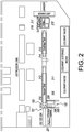
- a color feeder setting is positioned in proximity to the main extruder 101.
- the color feeder controls the amount of color agent added to the first polymeric material.
- the first polymeric material can be natural in color or colored using a color concentrate additive(s).
- a line speed control device is positioned in proximity to the main extruder 101to control the speed of the extruded material.
- the co-extruded tube is drawn down at a set speed to control outside outside diameter (OD), inside diameter (ID), and wall thickness.
- a main extruder heat profile is shown at 203
- a main extruder head pressure and screw speed indicator are shown at 204.
- the main extruder 101 is operated at a head pressure from about 13.8 megapascal to about 41.4 megapascal, a temperature from about 165°C to about 260°C, and a rotating screw speed from about 50 to about 100 revolutions per minute.
- the main extruder 101 is operated at a head pressure from about 13.8 megapascal to about 41.4 megapascal, a temperature from about 170°C to about 250°C, and a rotating screw speed from about 60 to about 90 revolutions per minute
- a coextruder heat profile is shown at 205, and a coextruder head pressure and screw speed indicator at 206.
- the coextruder 102 is operated at a head pressure from about 13.8 megapascal to about 41.4 megapascal, a temperature from about 170°C to about 275°C, and a rotating screw speed from about 75 to about 125 revolutions per minute.
- the coextruder 102 is operated at a head pressure from about 13.8 megapascal to about 41.4 megapascal, a temperature from about 190°C to about 260°C, and a rotating screw speed from about 85 to about 115 revolutions per minute.
- an entrance plate water setting is positioned at 207.
- An OD gauge is positioned at 208. The OD gauge measures in process the OD of the tubular workpiece.
- the extrusion line After leaving the coextrusion die 103, the extrusion line includes one or more vacuum cooling tanks that are operatively connected to the coextrusion die; one or more cooling/warming tanks that are operatively connected to the one or more vacuum cooling tanks; and a puller/cutter that operatively connected to the one or more cooling/warming tanks.
- the molten coextruded tubular workpiece After leaving the coextrusion die, the molten coextruded tubular workpiece enters the vacuum cooling tank though sizing rings.
- the first vacuum cooling tank is operatively connected to the coextrusion die.
- the tube is held under constant vacuum and temperature to maintain dimensional size and shape.
- the one or more vacuum cooling tanks are operated at a vacuum pressure from about 17236,9 Pa to about 86184,5 Pa (position 209) and a water temperature from about 15°C to about 38°C (position 210).
- the one or more vacuum cooling tanks are operated at a vacuum pressure from about 31026,4 Pa to about 72394,9 Pa (position 211) and a water temperature from about 21°C to about 33°C (position 212).
- the shaped co-extruded tube leaves the vacuum tank and enters a cooling/warming tank to prepare the tube to be cut to length at atmospheric pressure and a set constant temperature.
- the one or more cooling/warming tanks that are operatively connected to the one or more vacuum cooling tanks.
- the one or more cooling/warming tanks are operated at a temperature from about 26°C to about 49°C.
- the one or more cooling/warming tanks are operated at a temperature from about 33°C to about 44°C (position 213).
- a temperature control unit (e.g., thermolator) is located at 214.
- the temperature control unit prepares the tube to be cut to length at atmospheric pressure and a set constant temperature.
- the coextruded tube leaves the cooling/warming tank and enters the puller/cutter.
- the puller/cutter pulls the co-extruded tube at a set speed to control OD, ID, wall thickness as relative to rate of speed being drawn down on the coextrusion die and amount or vacuum in the tank and length as relative to the speed of the fly wheel cutter.
- the co-extruded tube leaves the front of the puller and enters directly into the fly wheel cutter.
- the fly wheel cutter is set at a certain speed and paired with the puller speed to give a desired length of cut to the co-extruded tube.
- the cut co-extruded tube is now a stylus pen barrel and packaged in sleeves for assembly in production.
- a puller belt height setting device is located at 215.
- a line speed control from the cutter is located at 216.
- the puller/cutter pulls the co-extruded tube at a set speed to control OD, ID, wall thickness as relative to rate of speed being drawn down on the coextrusion die and amount or vacuum in the tank and length as relative to the speed of the fly wheel cutter.
- the tubular workpiece is pulled at a set speed to control OD, ID, wall thickness, and length of cut.
- a cutter setting device is positioned at 217.
- the coextruded tube leaves the front of the puller and enters directly into the fly wheel cutter.
- the fly wheel cutter is set at a certain speed and paired with the puller speed to give a desired length of cut to the co-extruded tube.
- the cut co-extruded tube is now a stylus pen barrel and packaged in sleeves for assembly in production.
- the puller/cutter is operated at a speed from about 1 to about 400 feet per minute and a cut frequency from about 1 to about 800 cuts per minute.
- the puller/cutter is operated at a speed from about 225 to about 375 feet per minute and a cut frequency from about 450 to about 750 cuts per minute.
- the tubular workpiece is cut into cross-sectional slices comprising barrels having a length from about 50 to about 500 millimeters, an internal diameter from about 4 to about 10 millimeters, and an external diameter from about 4 to about 25 millimeters.
- the barrels have a length from about 75 to about 475 millimeters, an internal diameter from about 5 to about 9 millimeters, and an external diameter from about 5 to about 20 millimeters.
- the tubular workpiece is cut into cross-sectional slices comprising barrels having a length from about 100 to about 450 millimeters, an internal diameter from about 4 to about 10 millimeters, and an external diameter from about 6 to about 18 millimeters.
- the barrels Preferably, have a length from about 125 to about 400 millimeters, an internal diameter from about 5 to about 9 millimeters, and an external diameter from about 8 to about 16 millimeters.
- Additional processing steps can be used to further modify the tubular workpieces.
- grinding can include the process of removing material via abrasion as, for example, from materials too hard to be machined. Grinding can be performed to achieve several effects, including for example: (1) shaping the barrels, and/or (2) obtaining a high degree of dimensional accuracy and/or surface finish.
- the grinding process can include a rough grind that can remove a majority of material and then a fine grind to create the final tubular shape.
- the one or more outer layers have a thickness from about 1 to about 99 percent, or from about 1 to about 50 percent, or from about 1 to about 25 percent, of the total thickness of the one or more outer layers and the one or more inner layers.
- the one or more inner layers have a thickness from about 1 to about 99 percent, or from about 1 to about 50 percent, or from about 1 to about 25 percent, of the total thickness of the one or more outer layers and the one or more inner layers.
- the one or more outer layers have a thickness from about 1 to about 99 percent, preferably from about 1 to about 96 percent, of the total thickness of the one or more outer layers and the one or more inner layers
- the one or more inner layers have a thickness from about 1 to about 25 percent, preferably from about 1 to about 15 percent or less, more preferably from about 1 to about 10 percent or less, of the total thickness of the one or more outer layers and the one or more inner layers.
- the one or more outer layers have a thickness from about 0.01 to about 1.6 millimeters, and the one or more inner layers have a thickness from about 0.01 to about 0.4 millimeters.
- the one or more outer layers have a thickness from about 0.09 to about 1.4 millimeters, and the one or more inner layers have a thickness from about 0.01 to about 0.35 millimeters.
- the one or more outer layers comprise one or more decorative layers
- the first polymeric material comprises one or more color additives
- the tubular workpiece comprises one or more conductive layers overlaid by one or more decorative layers
- the cross-sectional slices of the tubular workpiece comprise stylus barrels.
- the tubular workpiece comprises one conductive layer overlaid by one decorative layer.
- the conductive layer preferably comprises polypropylene having carbon black filler dispersed therein
- the decorative layer preferably comprises polypropylene.
- thermoplastic resin compositions can be incorporated to impart special characteristics, such as additional strength, antimicrobial properties or other properties, to the barrels prepared therefrom.
- barrels that are most preferred have an inner layer capable of dissipating electrical charge. In this respect, two-layered barrels are most preferred from the standpoint of cost, ease of manufacture and performance.
- one or more layers of the stylus barrels also can have additives incorporated therein to impart other characteristics thereto, provided such additives do not interfere with the strength and electrically conductive properties of the stylus barrels or their manufacture.
- useful additives include one or more antioxidants; antistatic agents; lubricants; ultraviolet light absorbers; pigments such as titanium dioxide and nonconductive carbon black; delusterant, heat, light and oxidation stabilizers; opacifiers such as chalk and calcium carbonate; antimicrobial agents such as 2,4,4'-trichloro-2'-hydroxydiphenyl ether; flame retardants and various fillers such as talc, calcium carbonate, gypsum, kaoline, silica, and diatomaceous earth.
- Average particle diameter of such fillers should generally not exceed about 5 ⁇ m, and desirably is about 1 to about 3 ⁇ m.
- each such layer preferably comprises no more than about 10 weight percent filler, and more preferably about 0.5 to about 6 weight percent, based on the weight of the polymer component. Higher levels can interfere with processability and dispersion of conductive particles.
- this disclosure relates to a system for coextruding polymeric materials into multiple layers of desired thickness to form a tubular workpiece.
- the system comprises a coextrusion apparatus that includes a main extruder, a coextruder and a coextrusion die.
- the system further comprises one or more vacuum cooling tanks, one or more cooling/warming tanks, and a puller/cutter.
- the main extruder and the coextruder are operatively connected to the coextrusion die.
- the one or more vacuum cooling tanks are operatively connected to the coextrusion die.
- the one or more cooling/warming tanks are operatively connected to the one or more vacuum cooling tanks.
- the puller/cutter is operatively connected to the one or more cooling/warming tanks.
- the system can be operated manually, or can be automated, or the system can be a combination of manual and automated operation.
- a processor can be included for controlling operating conditions of the system.
- a software module can reside in RAM memory, flash memory, ROM memory, EPROM memory, EEPROM memory, registers, a hard disk, a removable disk, a CD-ROM, or any other form of storage medium known in the art.
- An exemplary storage medium can be connected to the processor, such that the processor can read information from, and write information to, the storage medium.
- the storage medium can be integral to the processor.
- the processor and the storage medium can reside in an Application Specific Integrated Circuit (ASIC).
- ASIC Application Specific Integrated Circuit
- the processor and the storage medium can reside as discrete components in a computing device. Additionally, in some embodiments, the events and/or actions of the method can reside as one or any combination or set of codes and/or instructions on a machine-readable medium and/or computer-readable medium, which can be incorporated into a computer program product.
- the functions described can be implemented in hardware, software, firmware, or any combination thereof. If implemented in software, the functions can be stored or transmitted as one or more instructions or code on a computer-readable medium.
- Computer-readable media includes both computer storage media and communication media including any medium that facilitates transfer of a computer program from one place to another.
- a storage medium can be any available media that can be accessed by a computer.
- such computer-readable media can comprise RAM, ROM, EEPROM, CD-ROM or other optical disk storage, magnetic disk storage or other magnetic storage devices, or any other medium that can be used to carry or store desired program code in the form of instructions or data structures, and that can be accessed by a computer.
- any connection can be termed a computer-readable medium.
- a computer-readable medium For example, if software is transmitted from a website, server, or other remote source using a coaxial cable, fiber optic cable, twisted pair, digital subscriber line (DSL), or wireless technologies such as infrared, radio, and microwave, then the coaxial cable, fiber optic cable, twisted pair, DSL, or wireless technologies such as infrared, radio, and microwave are included in the definition of medium.
- DSL digital subscriber line
- Disk disk and "disc” as used herein, include compact disc (CD), laser disc, optical disc, digital versatile disc (DVD), floppy disk and blu-ray disc where disks usually reproduce data magnetically, while discs usually reproduce data optically with lasers. Combinations of the above are included in the scope of computer-readable media.
- Computer program code for carrying out operations of embodiments of the present disclosure can be written in an object oriented, scripted or unscripted programming language such as Java, Perl, Smalltalk, C++, or the like.
- the computer program code for carrying out operations of embodiments of the present disclosure can also be written in conventional procedural programming languages, such as the "C" programming language or similar programming languages.
- Embodiments of the present disclosure are described herein with reference to flowchart illustrations and/or block diagrams of methods, apparatus (systems), and computer program products. It is understood that each block of the flowchart illustrations and/or block diagrams, and/or combinations of blocks in the flowchart illustrations and/or block diagrams, can be implemented by computer program instructions. These computer program instructions can be provided to a processor of a general purpose computer, special purpose computer, or other programmable data processing apparatus to produce a machine, such that the instructions, which execute via the processor of the computer or other programmable data processing apparatus, create mechanisms for implementing the functions/acts specified in the flowchart and/or block diagram block or blocks.
- These computer program instructions can also be stored in a computer-readable memory that can direct a computer or other programmable data processing apparatus to function in a particular manner, such that the instructions stored in the computer readable memory produce an article of manufacture including instruction means that implement the function/act specified in the flowchart and/or block diagram block(s).
- the computer program instructions can also be loaded onto a computer or other programmable data processing apparatus to cause a series of operational steps to be performed on the computer or other programmable apparatus to produce a computer-implemented process so that the instructions that execute on the computer or other programmable apparatus provide steps for implementing the functions/acts specified in the flowchart and/or block diagram block(s).
- computer program implemented steps or acts can be combined with operator or human implemented steps or acts in order to carry out an embodiment of the present disclosure.
Landscapes
- Engineering & Computer Science (AREA)
- Mechanical Engineering (AREA)
- Extrusion Moulding Of Plastics Or The Like (AREA)
- Laminated Bodies (AREA)
Claims (11)
- Verfahren zum Coextrudieren von Polymermaterialien in mehrere Schichten gewünschter Dicke zum Bilden eines rohrförmigen Werkstücks, wobei das Verfahren umfasst:Bereitstellen einer Coextrusionsvorrichtung, die einen Hauptextruder (101), einen Coextruder (102) und eine Coextrusionsdüse (103) umfasst, wobei der Hauptextruder (101) einen stationären Zylinder und eine rotierende Schnecke aufweist, der Coextruder (102) einen stationären Zylinder und eine rotierende Schnecke aufweist, wobei der Hauptextruder (101) und der Coextruder (102) betriebsmäßig mit der Coextrusionsdüse (103) verbunden sind, wobei die Coextrusionsvorrichtung auch einen oder mehrere Vakuumkühltanks (209, 210, 211, 212), die betriebsmäßig mit der Coextrusionsdüse (103) verbunden sind, einen oder mehrere Kühl-/Wärmetanks (213), die betriebsmäßig mit dem einen oder den mehreren Vakuumkühltanks (209, 210, 211, 212) verbunden sind, und eine Zieh-/Schneidvorrichtung (215), die betriebsmäßig mit dem einen oder den mehreren Kühl-/Wärmetanks (213) verbunden ist, umfasst;Fördern eines ersten Polymermaterials durch den Hauptextruder (101);Fördern eines zweiten Polymermaterials durch den Coextruder (102), wobei in dem zweiten Polymermaterial eine Menge elektrisch leitfähiger Partikel dispergiert ist, die wirksam sind, um dem rohrförmigen Werkstück elektrische Leitfähigkeit zu verleihen;gleichzeitiges Extrudieren des ersten Polymermaterials durch eine erste Öffnung der Coextrusionsdüse (103) und des zweiten Polymermaterials durch eine zweite Öffnung der Coextrusionsdüse (103), wobei die erste Öffnung und die zweite Öffnung so angeordnet sind, dass das erste und das zweite Polymermaterial während des Extrudierens sich vermischen und verschmelzen, wodurch das rohrförmige Werkstück gebildet wird, wobei das rohrförmige Werkstück in Form einer oder mehrerer äußerer Schichten, die das erste Polymermaterial umfassen, und einer oder mehrerer innerer Schichten, die das zweite Polymermaterial umfassen, extrudiert wird;Fördern des rohrförmigen Werkstücks durch den einen oder die mehreren Vakuumkühltanks (209, 210, 211, 212), den einen oder die mehreren Kühl-/Wärmetanks (213) und die Zieh-/Schneidvorrichtung (215);Schneiden von Querschnittsscheiben aus dem rohrförmigen Werkstück mit der Zieh-/Schneidvorrichtung (215), wobei die Querschnittsscheiben aus dem rohrförmigen Werkstück Taststiftzylinder umfassen; und wobei die Taststiftzylinder eine Länge von etwa 50 bis etwa 500 Millimeter, einen Innendurchmesser von etwa 4 bis etwa 10 Millimeter und einen Außendurchmesser von etwa 4 bis etwa 25 Millimeter aufweisen;wobei die eine oder mehreren äußeren Schichten eine Dicke von etwa 1 bis etwa 99 % der Gesamtdicke der einen oder mehreren äußeren Schichten und der einen oder mehreren inneren Schichten aufweisen, und wobei die eine oder mehreren inneren Schichten eine Dicke von etwa 1 bis etwa 99 % der Gesamtdicke der einen oder mehreren äußeren Schichten und der einen oder mehreren inneren Schichten aufweisen; undwobei der Hauptextruder (101) bei einem Kopfdruck von etwa 13,8 Megapascal bis etwa 41,4 Megapascal, einer Temperatur von etwa 165 °C bis etwa 260 °C und einer rotierenden Schneckengeschwindigkeit von etwa 50 bis etwa 100 Umdrehungen pro Minute betrieben wird; wobei der Coextruder (102) bei einem Kopfdruck von etwa 13,8 Megapascal bis etwa 41,4 Megapascal, einer Temperatur von etwa 170 °C bis etwa 275 °C und einer rotierenden Schneckengeschwindigkeit von etwa 75 bis etwa 125 Umdrehungen pro Minute betrieben wird; und wobei die Zieh-/Schneidvorrichtung (215) mit einer Geschwindigkeit von etwa 1 bis etwa 400 Fuß pro Minute und einer Schnittfrequenz von etwa 1 bis etwa 800 Schnitten pro Minute betrieben wird.
- Verfahren nach Anspruch 1, wobei der eine oder die mehreren Vakuumkühltanks (209, 210, 211, 212) bei einem Vakuumdruck von etwa 17236,9 Pa bis etwa 86184,5 Pa und einer Wassertemperatur von etwa 15 °C bis etwa 38 °C betrieben werden; und wobei der eine oder die mehreren Kühl-/Wärmetanks (213) bei einer Temperatur von etwa 26 °C bis etwa 49 °C betrieben werden.
- Verfahren nach Anspruch 1 oder 2, wobei das rohrförmige Werkstück bei konstantem Vakuum und konstanter Temperatur gehalten wird, um die Abmessungsgröße und -form beizubehalten, wenn es sich in dem einen oder mehreren Vakuumkühltanks (209, 210, 211, 212) befindet; wobei das rohrförmige Werkstück vorbereitet wird, um bei Atmosphärendruck und einer eingestellten konstanten Temperatur auf Länge geschnitten zu werden, wenn es sich in dem einen oder mehreren Kühl-/Wärmetanks (213) befindet; und wobei das rohrförmige Werkstück mit einer eingestellten Geschwindigkeit gezogen wird, um den Außendurchmesser, den Innendurchmesser, die Wanddicke und die Schnittlänge zu steuern, wenn es sich in der Zieh-/Schneidvorrichtung (215) befindet.
- Verfahren nach einem der Ansprüche 1 bis 3, wobei die eine oder mehreren äußeren Schichten eine Dicke von etwa 1 bis etwa 99 % der Gesamtdicke der einen oder mehreren äußeren Schichten und der einen oder mehreren inneren Schichten aufweisen, und wobei die eine oder mehreren inneren Schichten eine Dicke von etwa 1 bis etwa 25 % der Gesamtdicke der einen oder mehreren äußeren Schichten und der einen oder mehreren inneren Schichten aufweisen.
- Verfahren nach einem der Ansprüche 1 bis 4, wobei die eine oder mehreren äußeren Schichten eine Dicke von etwa 0,01 bis etwa 1,6 Millimeter aufweisen und wobei die eine oder mehreren inneren Schichten eine Dicke von etwa 0,01 bis etwa 0,4 Millimeter aufweisen.
- Verfahren nach einem der Ansprüche 1 bis 5, wobei das erste Polymermaterial eine Schmelzflussrate von etwa 3 bis etwa 8 Gramm pro 10 Minuten aufweist und wobei in dem zweiten Polymermaterial eine Menge elektrisch leitfähiger Partikel dispergiert ist, die eine Schmelzflussrate von etwa 2 bis etwa 5 Gramm pro 10 Minuten aufweist (bestimmt nach ASTM D-1238 bei 230 °C unter einer Last von 2,16 kg).
- Verfahren nach einem der Ansprüche 1 bis 6, wobei das erste Polymermaterial und das zweite Polymermaterial jeweils eine Schmelzflussrate aufweisen und wobei das Verhältnis der Schmelzflussrate des ersten Polymermaterials zum zweiten Polymermaterial etwa 0,1:1 bis etwa 0,5:1 beträgt.
- Verfahren nach einem der Ansprüche 1 bis 7, wobei das erste Polymermaterial und das zweite Polymermaterial ein thermoplastisches, ein duroplastisches oder ein elastomeres Material umfassen; und wobei die elektrisch leitfähigen Partikel Ruß, Kohlenstoffnanoröhrchen, Kohlenstofffasern, Kohlenstoffnanoröhrchendraht und beliebige Kombinationen davon umfassen.
- Verfahren nach einem der Ansprüche 1 bis 8, wobei das erste Polymermaterial und das zweite Polymermaterial ein thermoplastisches Material umfassen, das aus der Gruppe ausgewählt ist, die aus Polyethylen, Polypropylen, Polycarbonat, Polyamid, Polyvinylchlorid, Polyvinylidenchlorid, Polyacrylnitril, Polystyrol und Copolymeren sowie beliebigen Kombinationen davon besteht.
- Verfahren nach einem der Ansprüche 1 bis 9, wobei die eine oder mehreren äußeren Schichten eine oder mehrere Dekorschichten umfassen.
- Verfahren nach einem der Ansprüche 1 bis 10, wobei das rohrförmige Werkstück eine leitfähige Schicht umfasst, die von einer Dekorschicht überlagert ist, und wobei die leitfähige Schicht Polypropylen mit darin dispergiertem Rußfüllstoff umfasst und die Dekorschicht Polypropylen umfasst.
Applications Claiming Priority (2)
| Application Number | Priority Date | Filing Date | Title |
|---|---|---|---|
| US201562116139P | 2015-02-13 | 2015-02-13 | |
| PCT/IB2016/000204 WO2016128829A1 (en) | 2015-02-13 | 2016-02-04 | Coextrusion process for tubular articles and coextruded products |
Publications (2)
| Publication Number | Publication Date |
|---|---|
| EP3256306A1 EP3256306A1 (de) | 2017-12-20 |
| EP3256306B1 true EP3256306B1 (de) | 2021-10-27 |
Family
ID=55702022
Family Applications (1)
| Application Number | Title | Priority Date | Filing Date |
|---|---|---|---|
| EP16715603.3A Active EP3256306B1 (de) | 2015-02-13 | 2016-02-04 | Coextrusionsverfahren für ein rohrförmiges artikel |
Country Status (9)
| Country | Link |
|---|---|
| US (1) | US10960594B2 (de) |
| EP (1) | EP3256306B1 (de) |
| CN (1) | CN107530937A (de) |
| AR (1) | AR103704A1 (de) |
| AU (1) | AU2016217558A1 (de) |
| BR (1) | BR112017017337A2 (de) |
| CA (1) | CA2996758A1 (de) |
| MX (1) | MX2017010425A (de) |
| WO (1) | WO2016128829A1 (de) |
Families Citing this family (4)
| Publication number | Priority date | Publication date | Assignee | Title |
|---|---|---|---|---|
| CN109130128B (zh) * | 2018-11-05 | 2024-03-12 | 福建亚通新材料科技股份有限公司 | 一种供水管复合挤出成型装置 |
| CN109551933A (zh) * | 2019-01-09 | 2019-04-02 | 金凯 | 一种笔的生产方法 |
| DE102019215876A1 (de) | 2019-10-15 | 2021-04-15 | Greiner Extrusion Group Gmbh | Extrusionsvorrichtung und Extrusionsverfahren |
| CN114043700B (zh) * | 2021-10-29 | 2024-07-16 | 东莞市瓦特机械设备有限公司 | 液态硅胶双色高速注胶方法 |
Citations (1)
| Publication number | Priority date | Publication date | Assignee | Title |
|---|---|---|---|---|
| EP0297888A1 (de) * | 1987-07-02 | 1989-01-04 | Lion Corporation | Elektroleitfähige Harzzusammensetzung |
Family Cites Families (8)
| Publication number | Priority date | Publication date | Assignee | Title |
|---|---|---|---|---|
| US5360281A (en) | 1990-11-15 | 1994-11-01 | Revlon Consumer Products Corporation | Cosmetic pencil and method for making the same |
| JPH085167B2 (ja) * | 1992-01-06 | 1996-01-24 | パイロット インダストリーズ、インコーポレイテッド | フルオロポリマー複合材料製チューブおよびその製造方法 |
| DE19507025A1 (de) | 1995-03-01 | 1996-09-05 | Huels Chemische Werke Ag | Mehrschichtrohr mit elektrisch leitfähiger Innenschicht |
| JP3760631B2 (ja) * | 1998-05-15 | 2006-03-29 | 旭硝子株式会社 | 積層体 |
| JP3606280B2 (ja) | 2002-07-16 | 2005-01-05 | 日産自動車株式会社 | 樹脂製チューブ及び燃料系配管用チューブ |
| WO2005071301A1 (ja) * | 2004-01-27 | 2005-08-04 | Ube Industries, Ltd. | 積層チューブ |
| DE102004063915B4 (de) | 2004-04-06 | 2009-01-08 | Ekkehard Dipl.-Ing. Schneider | Gegen elektrostatische Aufladungen geschützte Behälter |
| CN103737887B (zh) * | 2013-12-27 | 2016-04-13 | 上海天力实业(集团)有限公司 | 一种多层热塑性塑料管的加工方法 |
-
2016
- 2016-02-04 US US15/550,571 patent/US10960594B2/en active Active
- 2016-02-04 AU AU2016217558A patent/AU2016217558A1/en not_active Abandoned
- 2016-02-04 CA CA2996758A patent/CA2996758A1/en not_active Abandoned
- 2016-02-04 CN CN201680009927.9A patent/CN107530937A/zh active Pending
- 2016-02-04 WO PCT/IB2016/000204 patent/WO2016128829A1/en not_active Ceased
- 2016-02-04 MX MX2017010425A patent/MX2017010425A/es unknown
- 2016-02-04 EP EP16715603.3A patent/EP3256306B1/de active Active
- 2016-02-04 BR BR112017017337A patent/BR112017017337A2/pt active Search and Examination
- 2016-02-12 AR ARP160100400A patent/AR103704A1/es unknown
Patent Citations (1)
| Publication number | Priority date | Publication date | Assignee | Title |
|---|---|---|---|---|
| EP0297888A1 (de) * | 1987-07-02 | 1989-01-04 | Lion Corporation | Elektroleitfähige Harzzusammensetzung |
Also Published As
| Publication number | Publication date |
|---|---|
| AU2016217558A1 (en) | 2017-08-31 |
| BR112017017337A2 (pt) | 2018-04-03 |
| CA2996758A1 (en) | 2016-08-18 |
| AR103704A1 (es) | 2017-05-31 |
| EP3256306A1 (de) | 2017-12-20 |
| US20180029277A1 (en) | 2018-02-01 |
| WO2016128829A1 (en) | 2016-08-18 |
| MX2017010425A (es) | 2018-06-06 |
| CN107530937A (zh) | 2018-01-02 |
| US10960594B2 (en) | 2021-03-30 |
Similar Documents
| Publication | Publication Date | Title |
|---|---|---|
| EP3256306B1 (de) | Coextrusionsverfahren für ein rohrförmiges artikel | |
| EP2277675B1 (de) | Hohlkörper aus schlagzähem Polyamid | |
| EP0730115B1 (de) | Mehrschichtrohr mit elektrisch leitfähiger Innenschicht | |
| CN1128846C (zh) | 具有抗静电性质的产品 | |
| CN1034607C (zh) | 复合管制品,特别是汽油管以及这种制品的制法 | |
| AU2001265114B2 (en) | Thermoplastic tubing | |
| JP4964365B2 (ja) | 熱可塑性多層中空体及びその製造方法 | |
| JPH08323122A (ja) | 多層プラスチック製燃料フィルタ | |
| EP1077341A2 (de) | Mehrschichtiges Kunststoffrohr für ein System zur Handhabung von Flüssigkeiten und Dämpfen | |
| JPH0353114B2 (de) | ||
| AU2001265114A1 (en) | Thermoplastic tubing | |
| CA2649165A1 (en) | Multilayer polymer structure | |
| JP5604820B2 (ja) | 成形体及び中空成形体の製造方法 | |
| US6172155B1 (en) | Multi-layered article having a conductive surface and a non-conductive core and process for making the same | |
| JPH07195635A (ja) | 多層構造体およびその製造方法 | |
| JPH0753824A (ja) | 樹脂組成物 | |
| CN1532042A (zh) | 生产层压发泡片材的方法 | |
| JP3178027B2 (ja) | 中芯発泡多層シートの製造方法 | |
| Rost et al. | THV in automotive fuel systems management | |
| MXPA06001911A (en) | Impact-modified polyamide hollow body | |
| CN106564206A (zh) | 一种五层防渗导静电聚乙烯复合管生产系统和生产方法 | |
| HK1027826B (en) | Product with antistatic properties |
Legal Events
| Date | Code | Title | Description |
|---|---|---|---|
| STAA | Information on the status of an ep patent application or granted ep patent |
Free format text: STATUS: THE INTERNATIONAL PUBLICATION HAS BEEN MADE |
|
| PUAI | Public reference made under article 153(3) epc to a published international application that has entered the european phase |
Free format text: ORIGINAL CODE: 0009012 |
|
| STAA | Information on the status of an ep patent application or granted ep patent |
Free format text: STATUS: REQUEST FOR EXAMINATION WAS MADE |
|
| 17P | Request for examination filed |
Effective date: 20170811 |
|
| AK | Designated contracting states |
Kind code of ref document: A1 Designated state(s): AL AT BE BG CH CY CZ DE DK EE ES FI FR GB GR HR HU IE IS IT LI LT LU LV MC MK MT NL NO PL PT RO RS SE SI SK SM TR |
|
| AX | Request for extension of the european patent |
Extension state: BA ME |
|
| DAV | Request for validation of the european patent (deleted) | ||
| DAX | Request for extension of the european patent (deleted) | ||
| STAA | Information on the status of an ep patent application or granted ep patent |
Free format text: STATUS: EXAMINATION IS IN PROGRESS |
|
| 17Q | First examination report despatched |
Effective date: 20200707 |
|
| REG | Reference to a national code |
Ref country code: DE Ref legal event code: R079 Ref document number: 602016065372 Country of ref document: DE Free format text: PREVIOUS MAIN CLASS: B29C0047060000 Ipc: B29C0048060000 |
|
| GRAP | Despatch of communication of intention to grant a patent |
Free format text: ORIGINAL CODE: EPIDOSNIGR1 |
|
| STAA | Information on the status of an ep patent application or granted ep patent |
Free format text: STATUS: GRANT OF PATENT IS INTENDED |
|
| RIC1 | Information provided on ipc code assigned before grant |
Ipc: B29C 48/90 20190101ALI20210504BHEP Ipc: B29C 48/92 20190101ALI20210504BHEP Ipc: B29C 48/06 20190101AFI20210504BHEP |
|
| INTG | Intention to grant announced |
Effective date: 20210531 |
|
| RAP3 | Party data changed (applicant data changed or rights of an application transferred) |
Owner name: SOCIETE BIC S.A. |
|
| GRAS | Grant fee paid |
Free format text: ORIGINAL CODE: EPIDOSNIGR3 |
|
| GRAA | (expected) grant |
Free format text: ORIGINAL CODE: 0009210 |
|
| STAA | Information on the status of an ep patent application or granted ep patent |
Free format text: STATUS: THE PATENT HAS BEEN GRANTED |
|
| AK | Designated contracting states |
Kind code of ref document: B1 Designated state(s): AL AT BE BG CH CY CZ DE DK EE ES FI FR GB GR HR HU IE IS IT LI LT LU LV MC MK MT NL NO PL PT RO RS SE SI SK SM TR |
|
| REG | Reference to a national code |
Ref country code: GB Ref legal event code: FG4D |
|
| REG | Reference to a national code |
Ref country code: CH Ref legal event code: EP |
|
| REG | Reference to a national code |
Ref country code: AT Ref legal event code: REF Ref document number: 1441401 Country of ref document: AT Kind code of ref document: T Effective date: 20211115 |
|
| REG | Reference to a national code |
Ref country code: DE Ref legal event code: R096 Ref document number: 602016065372 Country of ref document: DE |
|
| REG | Reference to a national code |
Ref country code: IE Ref legal event code: FG4D |
|
| REG | Reference to a national code |
Ref country code: LT Ref legal event code: MG9D |
|
| REG | Reference to a national code |
Ref country code: NL Ref legal event code: MP Effective date: 20211027 |
|
| REG | Reference to a national code |
Ref country code: AT Ref legal event code: MK05 Ref document number: 1441401 Country of ref document: AT Kind code of ref document: T Effective date: 20211027 |
|
| PG25 | Lapsed in a contracting state [announced via postgrant information from national office to epo] |
Ref country code: RS Free format text: LAPSE BECAUSE OF FAILURE TO SUBMIT A TRANSLATION OF THE DESCRIPTION OR TO PAY THE FEE WITHIN THE PRESCRIBED TIME-LIMIT Effective date: 20211027 Ref country code: LT Free format text: LAPSE BECAUSE OF FAILURE TO SUBMIT A TRANSLATION OF THE DESCRIPTION OR TO PAY THE FEE WITHIN THE PRESCRIBED TIME-LIMIT Effective date: 20211027 Ref country code: FI Free format text: LAPSE BECAUSE OF FAILURE TO SUBMIT A TRANSLATION OF THE DESCRIPTION OR TO PAY THE FEE WITHIN THE PRESCRIBED TIME-LIMIT Effective date: 20211027 Ref country code: BG Free format text: LAPSE BECAUSE OF FAILURE TO SUBMIT A TRANSLATION OF THE DESCRIPTION OR TO PAY THE FEE WITHIN THE PRESCRIBED TIME-LIMIT Effective date: 20220127 Ref country code: AT Free format text: LAPSE BECAUSE OF FAILURE TO SUBMIT A TRANSLATION OF THE DESCRIPTION OR TO PAY THE FEE WITHIN THE PRESCRIBED TIME-LIMIT Effective date: 20211027 |
|
| PG25 | Lapsed in a contracting state [announced via postgrant information from national office to epo] |
Ref country code: IS Free format text: LAPSE BECAUSE OF FAILURE TO SUBMIT A TRANSLATION OF THE DESCRIPTION OR TO PAY THE FEE WITHIN THE PRESCRIBED TIME-LIMIT Effective date: 20220227 Ref country code: SE Free format text: LAPSE BECAUSE OF FAILURE TO SUBMIT A TRANSLATION OF THE DESCRIPTION OR TO PAY THE FEE WITHIN THE PRESCRIBED TIME-LIMIT Effective date: 20211027 Ref country code: PT Free format text: LAPSE BECAUSE OF FAILURE TO SUBMIT A TRANSLATION OF THE DESCRIPTION OR TO PAY THE FEE WITHIN THE PRESCRIBED TIME-LIMIT Effective date: 20220228 Ref country code: PL Free format text: LAPSE BECAUSE OF FAILURE TO SUBMIT A TRANSLATION OF THE DESCRIPTION OR TO PAY THE FEE WITHIN THE PRESCRIBED TIME-LIMIT Effective date: 20211027 Ref country code: NO Free format text: LAPSE BECAUSE OF FAILURE TO SUBMIT A TRANSLATION OF THE DESCRIPTION OR TO PAY THE FEE WITHIN THE PRESCRIBED TIME-LIMIT Effective date: 20220127 Ref country code: NL Free format text: LAPSE BECAUSE OF FAILURE TO SUBMIT A TRANSLATION OF THE DESCRIPTION OR TO PAY THE FEE WITHIN THE PRESCRIBED TIME-LIMIT Effective date: 20211027 Ref country code: LV Free format text: LAPSE BECAUSE OF FAILURE TO SUBMIT A TRANSLATION OF THE DESCRIPTION OR TO PAY THE FEE WITHIN THE PRESCRIBED TIME-LIMIT Effective date: 20211027 Ref country code: HR Free format text: LAPSE BECAUSE OF FAILURE TO SUBMIT A TRANSLATION OF THE DESCRIPTION OR TO PAY THE FEE WITHIN THE PRESCRIBED TIME-LIMIT Effective date: 20211027 Ref country code: GR Free format text: LAPSE BECAUSE OF FAILURE TO SUBMIT A TRANSLATION OF THE DESCRIPTION OR TO PAY THE FEE WITHIN THE PRESCRIBED TIME-LIMIT Effective date: 20220128 Ref country code: ES Free format text: LAPSE BECAUSE OF FAILURE TO SUBMIT A TRANSLATION OF THE DESCRIPTION OR TO PAY THE FEE WITHIN THE PRESCRIBED TIME-LIMIT Effective date: 20211027 |
|
| REG | Reference to a national code |
Ref country code: DE Ref legal event code: R097 Ref document number: 602016065372 Country of ref document: DE |
|
| PG25 | Lapsed in a contracting state [announced via postgrant information from national office to epo] |
Ref country code: SM Free format text: LAPSE BECAUSE OF FAILURE TO SUBMIT A TRANSLATION OF THE DESCRIPTION OR TO PAY THE FEE WITHIN THE PRESCRIBED TIME-LIMIT Effective date: 20211027 Ref country code: SK Free format text: LAPSE BECAUSE OF FAILURE TO SUBMIT A TRANSLATION OF THE DESCRIPTION OR TO PAY THE FEE WITHIN THE PRESCRIBED TIME-LIMIT Effective date: 20211027 Ref country code: RO Free format text: LAPSE BECAUSE OF FAILURE TO SUBMIT A TRANSLATION OF THE DESCRIPTION OR TO PAY THE FEE WITHIN THE PRESCRIBED TIME-LIMIT Effective date: 20211027 Ref country code: EE Free format text: LAPSE BECAUSE OF FAILURE TO SUBMIT A TRANSLATION OF THE DESCRIPTION OR TO PAY THE FEE WITHIN THE PRESCRIBED TIME-LIMIT Effective date: 20211027 Ref country code: DK Free format text: LAPSE BECAUSE OF FAILURE TO SUBMIT A TRANSLATION OF THE DESCRIPTION OR TO PAY THE FEE WITHIN THE PRESCRIBED TIME-LIMIT Effective date: 20211027 Ref country code: CZ Free format text: LAPSE BECAUSE OF FAILURE TO SUBMIT A TRANSLATION OF THE DESCRIPTION OR TO PAY THE FEE WITHIN THE PRESCRIBED TIME-LIMIT Effective date: 20211027 |
|
| PLBE | No opposition filed within time limit |
Free format text: ORIGINAL CODE: 0009261 |
|
| STAA | Information on the status of an ep patent application or granted ep patent |
Free format text: STATUS: NO OPPOSITION FILED WITHIN TIME LIMIT |
|
| PG25 | Lapsed in a contracting state [announced via postgrant information from national office to epo] |
Ref country code: MC Free format text: LAPSE BECAUSE OF FAILURE TO SUBMIT A TRANSLATION OF THE DESCRIPTION OR TO PAY THE FEE WITHIN THE PRESCRIBED TIME-LIMIT Effective date: 20211027 |
|
| 26N | No opposition filed |
Effective date: 20220728 |
|
| REG | Reference to a national code |
Ref country code: CH Ref legal event code: PL |
|
| REG | Reference to a national code |
Ref country code: BE Ref legal event code: MM Effective date: 20220228 |
|
| PG25 | Lapsed in a contracting state [announced via postgrant information from national office to epo] |
Ref country code: LU Free format text: LAPSE BECAUSE OF NON-PAYMENT OF DUE FEES Effective date: 20220204 Ref country code: AL Free format text: LAPSE BECAUSE OF FAILURE TO SUBMIT A TRANSLATION OF THE DESCRIPTION OR TO PAY THE FEE WITHIN THE PRESCRIBED TIME-LIMIT Effective date: 20211027 |
|
| PG25 | Lapsed in a contracting state [announced via postgrant information from national office to epo] |
Ref country code: SI Free format text: LAPSE BECAUSE OF FAILURE TO SUBMIT A TRANSLATION OF THE DESCRIPTION OR TO PAY THE FEE WITHIN THE PRESCRIBED TIME-LIMIT Effective date: 20211027 |
|
| PG25 | Lapsed in a contracting state [announced via postgrant information from national office to epo] |
Ref country code: LI Free format text: LAPSE BECAUSE OF NON-PAYMENT OF DUE FEES Effective date: 20220228 Ref country code: IE Free format text: LAPSE BECAUSE OF NON-PAYMENT OF DUE FEES Effective date: 20220204 Ref country code: CH Free format text: LAPSE BECAUSE OF NON-PAYMENT OF DUE FEES Effective date: 20220228 |
|
| PG25 | Lapsed in a contracting state [announced via postgrant information from national office to epo] |
Ref country code: BE Free format text: LAPSE BECAUSE OF NON-PAYMENT OF DUE FEES Effective date: 20220228 |
|
| P01 | Opt-out of the competence of the unified patent court (upc) registered |
Effective date: 20230530 |
|
| PG25 | Lapsed in a contracting state [announced via postgrant information from national office to epo] |
Ref country code: HU Free format text: LAPSE BECAUSE OF FAILURE TO SUBMIT A TRANSLATION OF THE DESCRIPTION OR TO PAY THE FEE WITHIN THE PRESCRIBED TIME-LIMIT; INVALID AB INITIO Effective date: 20160204 |
|
| PG25 | Lapsed in a contracting state [announced via postgrant information from national office to epo] |
Ref country code: MK Free format text: LAPSE BECAUSE OF FAILURE TO SUBMIT A TRANSLATION OF THE DESCRIPTION OR TO PAY THE FEE WITHIN THE PRESCRIBED TIME-LIMIT Effective date: 20211027 Ref country code: CY Free format text: LAPSE BECAUSE OF FAILURE TO SUBMIT A TRANSLATION OF THE DESCRIPTION OR TO PAY THE FEE WITHIN THE PRESCRIBED TIME-LIMIT Effective date: 20211027 |
|
| PG25 | Lapsed in a contracting state [announced via postgrant information from national office to epo] |
Ref country code: MT Free format text: LAPSE BECAUSE OF FAILURE TO SUBMIT A TRANSLATION OF THE DESCRIPTION OR TO PAY THE FEE WITHIN THE PRESCRIBED TIME-LIMIT Effective date: 20211027 |
|
| PG25 | Lapsed in a contracting state [announced via postgrant information from national office to epo] |
Ref country code: TR Free format text: LAPSE BECAUSE OF FAILURE TO SUBMIT A TRANSLATION OF THE DESCRIPTION OR TO PAY THE FEE WITHIN THE PRESCRIBED TIME-LIMIT Effective date: 20211027 |
|
| PGFP | Annual fee paid to national office [announced via postgrant information from national office to epo] |
Ref country code: GB Payment date: 20260219 Year of fee payment: 11 |
|
| PGFP | Annual fee paid to national office [announced via postgrant information from national office to epo] |
Ref country code: DE Payment date: 20260217 Year of fee payment: 11 |
|
| PGFP | Annual fee paid to national office [announced via postgrant information from national office to epo] |
Ref country code: IT Payment date: 20260227 Year of fee payment: 11 |
|
| PGFP | Annual fee paid to national office [announced via postgrant information from national office to epo] |
Ref country code: FR Payment date: 20260219 Year of fee payment: 11 |