EP3256384B1 - Système et appareil - Google Patents
Système et appareil Download PDFInfo
- Publication number
- EP3256384B1 EP3256384B1 EP16703843.9A EP16703843A EP3256384B1 EP 3256384 B1 EP3256384 B1 EP 3256384B1 EP 16703843 A EP16703843 A EP 16703843A EP 3256384 B1 EP3256384 B1 EP 3256384B1
- Authority
- EP
- European Patent Office
- Prior art keywords
- reservoir
- dispenser
- liquid
- pathway
- smoking
- Prior art date
- Legal status (The legal status is an assumption and is not a legal conclusion. Google has not performed a legal analysis and makes no representation as to the accuracy of the status listed.)
- Active
Links
Images








Classifications
-
- B—PERFORMING OPERATIONS; TRANSPORTING
- B67—OPENING, CLOSING OR CLEANING BOTTLES, JARS OR SIMILAR CONTAINERS; LIQUID HANDLING
- B67D—DISPENSING, DELIVERING OR TRANSFERRING LIQUIDS, NOT OTHERWISE PROVIDED FOR
- B67D7/00—Apparatus or devices for transferring liquids from bulk storage containers or reservoirs into vehicles or into portable containers, e.g. for retail sale purposes
- B67D7/02—Apparatus or devices for transferring liquids from bulk storage containers or reservoirs into vehicles or into portable containers, e.g. for retail sale purposes for transferring liquids other than fuel or lubricants
- B67D7/0288—Container connection means
- B67D7/0294—Combined with valves
-
- B—PERFORMING OPERATIONS; TRANSPORTING
- B65—CONVEYING; PACKING; STORING; HANDLING THIN OR FILAMENTARY MATERIAL
- B65B—MACHINES, APPARATUS OR DEVICES FOR, OR METHODS OF, PACKAGING ARTICLES OR MATERIALS; UNPACKING
- B65B39/00—Nozzles, funnels or guides for introducing articles or materials into containers or wrappers
- B65B39/001—Nozzles, funnels or guides for introducing articles or materials into containers or wrappers with flow cut-off means, e.g. valves
- B65B39/004—Nozzles, funnels or guides for introducing articles or materials into containers or wrappers with flow cut-off means, e.g. valves moving linearly
-
- B—PERFORMING OPERATIONS; TRANSPORTING
- B65—CONVEYING; PACKING; STORING; HANDLING THIN OR FILAMENTARY MATERIAL
- B65B—MACHINES, APPARATUS OR DEVICES FOR, OR METHODS OF, PACKAGING ARTICLES OR MATERIALS; UNPACKING
- B65B39/00—Nozzles, funnels or guides for introducing articles or materials into containers or wrappers
- B65B39/001—Nozzles, funnels or guides for introducing articles or materials into containers or wrappers with flow cut-off means, e.g. valves
-
- A—HUMAN NECESSITIES
- A24—TOBACCO; CIGARS; CIGARETTES; SIMULATED SMOKING DEVICES; SMOKERS' REQUISITES
- A24F—SMOKERS' REQUISITES; MATCH BOXES; SIMULATED SMOKING DEVICES
- A24F40/00—Electrically operated smoking devices; Component parts thereof; Manufacture thereof; Maintenance or testing thereof; Charging means specially adapted therefor
- A24F40/40—Constructional details, e.g. connection of cartridges and battery parts
- A24F40/48—Fluid transfer means, e.g. pumps
- A24F40/485—Valves; Apertures
-
- B—PERFORMING OPERATIONS; TRANSPORTING
- B65—CONVEYING; PACKING; STORING; HANDLING THIN OR FILAMENTARY MATERIAL
- B65D—CONTAINERS FOR STORAGE OR TRANSPORT OF ARTICLES OR MATERIALS, e.g. BAGS, BARRELS, BOTTLES, BOXES, CANS, CARTONS, CRATES, DRUMS, JARS, TANKS, HOPPERS, FORWARDING CONTAINERS; ACCESSORIES, CLOSURES, OR FITTINGS THEREFOR; PACKAGING ELEMENTS; PACKAGES
- B65D47/00—Closures with filling and discharging, or with discharging, devices
- B65D47/04—Closures with discharging devices other than pumps
- B65D47/06—Closures with discharging devices other than pumps with pouring spouts or tubes; with discharge nozzles or passages
-
- A—HUMAN NECESSITIES
- A24—TOBACCO; CIGARS; CIGARETTES; SIMULATED SMOKING DEVICES; SMOKERS' REQUISITES
- A24F—SMOKERS' REQUISITES; MATCH BOXES; SIMULATED SMOKING DEVICES
- A24F40/00—Electrically operated smoking devices; Component parts thereof; Manufacture thereof; Maintenance or testing thereof; Charging means specially adapted therefor
-
- A—HUMAN NECESSITIES
- A24—TOBACCO; CIGARS; CIGARETTES; SIMULATED SMOKING DEVICES; SMOKERS' REQUISITES
- A24F—SMOKERS' REQUISITES; MATCH BOXES; SIMULATED SMOKING DEVICES
- A24F40/00—Electrically operated smoking devices; Component parts thereof; Manufacture thereof; Maintenance or testing thereof; Charging means specially adapted therefor
- A24F40/40—Constructional details, e.g. connection of cartridges and battery parts
- A24F40/48—Fluid transfer means, e.g. pumps
-
- A—HUMAN NECESSITIES
- A24—TOBACCO; CIGARS; CIGARETTES; SIMULATED SMOKING DEVICES; SMOKERS' REQUISITES
- A24F—SMOKERS' REQUISITES; MATCH BOXES; SIMULATED SMOKING DEVICES
- A24F47/00—Smokers' requisites not otherwise provided for
-
- A—HUMAN NECESSITIES
- A61—MEDICAL OR VETERINARY SCIENCE; HYGIENE
- A61M—DEVICES FOR INTRODUCING MEDIA INTO, OR ONTO, THE BODY; DEVICES FOR TRANSDUCING BODY MEDIA OR FOR TAKING MEDIA FROM THE BODY; DEVICES FOR PRODUCING OR ENDING SLEEP OR STUPOR
- A61M11/00—Sprayers or atomisers specially adapted for therapeutic purposes
- A61M11/04—Sprayers or atomisers specially adapted for therapeutic purposes operated by the vapour pressure of the liquid to be sprayed or atomised
- A61M11/041—Sprayers or atomisers specially adapted for therapeutic purposes operated by the vapour pressure of the liquid to be sprayed or atomised using heaters
- A61M11/042—Sprayers or atomisers specially adapted for therapeutic purposes operated by the vapour pressure of the liquid to be sprayed or atomised using heaters electrical
-
- A—HUMAN NECESSITIES
- A61—MEDICAL OR VETERINARY SCIENCE; HYGIENE
- A61M—DEVICES FOR INTRODUCING MEDIA INTO, OR ONTO, THE BODY; DEVICES FOR TRANSDUCING BODY MEDIA OR FOR TAKING MEDIA FROM THE BODY; DEVICES FOR PRODUCING OR ENDING SLEEP OR STUPOR
- A61M15/00—Inhalators
- A61M15/06—Inhaling appliances shaped like cigars, cigarettes or pipes
-
- B—PERFORMING OPERATIONS; TRANSPORTING
- B05—SPRAYING OR ATOMISING IN GENERAL; APPLYING FLUENT MATERIALS TO SURFACES, IN GENERAL
- B05B—SPRAYING APPARATUS; ATOMISING APPARATUS; NOZZLES
- B05B11/00—Single-unit hand-held apparatus in which flow of contents is produced by the muscular force of the operator at the moment of use
- B05B11/0005—Components or details
- B05B11/0037—Containers
- B05B11/0039—Containers associated with means for compensating the pressure difference between the ambient pressure and the pressure inside the container, e.g. pressure relief means
- B05B11/0044—Containers associated with means for compensating the pressure difference between the ambient pressure and the pressure inside the container, e.g. pressure relief means compensating underpressure by ingress of atmospheric air into the container, i.e. with venting means
-
- B—PERFORMING OPERATIONS; TRANSPORTING
- B05—SPRAYING OR ATOMISING IN GENERAL; APPLYING FLUENT MATERIALS TO SURFACES, IN GENERAL
- B05B—SPRAYING APPARATUS; ATOMISING APPARATUS; NOZZLES
- B05B11/00—Single-unit hand-held apparatus in which flow of contents is produced by the muscular force of the operator at the moment of use
- B05B11/0005—Components or details
- B05B11/0097—Means for filling or refilling the sprayer
-
- B—PERFORMING OPERATIONS; TRANSPORTING
- B65—CONVEYING; PACKING; STORING; HANDLING THIN OR FILAMENTARY MATERIAL
- B65B—MACHINES, APPARATUS OR DEVICES FOR, OR METHODS OF, PACKAGING ARTICLES OR MATERIALS; UNPACKING
- B65B3/00—Packaging plastic material, semiliquids, liquids or mixed solids and liquids, in individual containers or receptacles, e.g. bags, sacks, boxes, cartons, cans, or jars
- B65B3/04—Methods of, or means for, filling the material into the containers or receptacles
-
- B—PERFORMING OPERATIONS; TRANSPORTING
- B65—CONVEYING; PACKING; STORING; HANDLING THIN OR FILAMENTARY MATERIAL
- B65B—MACHINES, APPARATUS OR DEVICES FOR, OR METHODS OF, PACKAGING ARTICLES OR MATERIALS; UNPACKING
- B65B3/00—Packaging plastic material, semiliquids, liquids or mixed solids and liquids, in individual containers or receptacles, e.g. bags, sacks, boxes, cartons, cans, or jars
- B65B3/04—Methods of, or means for, filling the material into the containers or receptacles
- B65B3/06—Methods of, or means for, filling the material into the containers or receptacles by gravity flow
-
- B—PERFORMING OPERATIONS; TRANSPORTING
- B65—CONVEYING; PACKING; STORING; HANDLING THIN OR FILAMENTARY MATERIAL
- B65B—MACHINES, APPARATUS OR DEVICES FOR, OR METHODS OF, PACKAGING ARTICLES OR MATERIALS; UNPACKING
- B65B3/00—Packaging plastic material, semiliquids, liquids or mixed solids and liquids, in individual containers or receptacles, e.g. bags, sacks, boxes, cartons, cans, or jars
- B65B3/04—Methods of, or means for, filling the material into the containers or receptacles
- B65B3/10—Methods of, or means for, filling the material into the containers or receptacles by application of pressure to material
- B65B3/12—Methods of, or means for, filling the material into the containers or receptacles by application of pressure to material mechanically, e.g. by pistons or pumps
-
- B—PERFORMING OPERATIONS; TRANSPORTING
- B65—CONVEYING; PACKING; STORING; HANDLING THIN OR FILAMENTARY MATERIAL
- B65D—CONTAINERS FOR STORAGE OR TRANSPORT OF ARTICLES OR MATERIALS, e.g. BAGS, BARRELS, BOTTLES, BOXES, CANS, CARTONS, CRATES, DRUMS, JARS, TANKS, HOPPERS, FORWARDING CONTAINERS; ACCESSORIES, CLOSURES, OR FITTINGS THEREFOR; PACKAGING ELEMENTS; PACKAGES
- B65D47/00—Closures with filling and discharging, or with discharging, devices
- B65D47/04—Closures with discharging devices other than pumps
- B65D47/06—Closures with discharging devices other than pumps with pouring spouts or tubes; with discharge nozzles or passages
- B65D47/08—Closures with discharging devices other than pumps with pouring spouts or tubes; with discharge nozzles or passages having articulated or hinged closures
- B65D47/0804—Closures with discharging devices other than pumps with pouring spouts or tubes; with discharge nozzles or passages having articulated or hinged closures integrally formed with the base element provided with the spout or discharge passage
- B65D47/0833—Hinges without elastic bias
-
- B—PERFORMING OPERATIONS; TRANSPORTING
- B65—CONVEYING; PACKING; STORING; HANDLING THIN OR FILAMENTARY MATERIAL
- B65D—CONTAINERS FOR STORAGE OR TRANSPORT OF ARTICLES OR MATERIALS, e.g. BAGS, BARRELS, BOTTLES, BOXES, CANS, CARTONS, CRATES, DRUMS, JARS, TANKS, HOPPERS, FORWARDING CONTAINERS; ACCESSORIES, CLOSURES, OR FITTINGS THEREFOR; PACKAGING ELEMENTS; PACKAGES
- B65D47/00—Closures with filling and discharging, or with discharging, devices
- B65D47/04—Closures with discharging devices other than pumps
- B65D47/20—Closures with discharging devices other than pumps comprising hand-operated members for controlling discharge
- B65D47/24—Closures with discharging devices other than pumps comprising hand-operated members for controlling discharge with poppet valves or lift valves, i.e. valves opening or closing a passageway by a relative motion substantially perpendicular to the plane of the seat
- B65D47/241—Closures with discharging devices other than pumps comprising hand-operated members for controlling discharge with poppet valves or lift valves, i.e. valves opening or closing a passageway by a relative motion substantially perpendicular to the plane of the seat the valve being opened or closed by actuating a cap-like element
- B65D47/243—Closures with discharging devices other than pumps comprising hand-operated members for controlling discharge with poppet valves or lift valves, i.e. valves opening or closing a passageway by a relative motion substantially perpendicular to the plane of the seat the valve being opened or closed by actuating a cap-like element moving linearly, i.e. without rotational motion
-
- B—PERFORMING OPERATIONS; TRANSPORTING
- B65—CONVEYING; PACKING; STORING; HANDLING THIN OR FILAMENTARY MATERIAL
- B65D—CONTAINERS FOR STORAGE OR TRANSPORT OF ARTICLES OR MATERIALS, e.g. BAGS, BARRELS, BOTTLES, BOXES, CANS, CARTONS, CRATES, DRUMS, JARS, TANKS, HOPPERS, FORWARDING CONTAINERS; ACCESSORIES, CLOSURES, OR FITTINGS THEREFOR; PACKAGING ELEMENTS; PACKAGES
- B65D47/00—Closures with filling and discharging, or with discharging, devices
- B65D47/04—Closures with discharging devices other than pumps
- B65D47/32—Closures with discharging devices other than pumps with means for venting
-
- B—PERFORMING OPERATIONS; TRANSPORTING
- B65—CONVEYING; PACKING; STORING; HANDLING THIN OR FILAMENTARY MATERIAL
- B65D—CONTAINERS FOR STORAGE OR TRANSPORT OF ARTICLES OR MATERIALS, e.g. BAGS, BARRELS, BOTTLES, BOXES, CANS, CARTONS, CRATES, DRUMS, JARS, TANKS, HOPPERS, FORWARDING CONTAINERS; ACCESSORIES, CLOSURES, OR FITTINGS THEREFOR; PACKAGING ELEMENTS; PACKAGES
- B65D83/00—Containers or packages with special means for dispensing contents
- B65D83/14—Containers for dispensing liquid or semi-liquid contents by internal gaseous pressure, i.e. aerosol containers comprising propellant
- B65D83/42—Filling or charging means
-
- B—PERFORMING OPERATIONS; TRANSPORTING
- B67—OPENING, CLOSING OR CLEANING BOTTLES, JARS OR SIMILAR CONTAINERS; LIQUID HANDLING
- B67D—DISPENSING, DELIVERING OR TRANSFERRING LIQUIDS, NOT OTHERWISE PROVIDED FOR
- B67D7/00—Apparatus or devices for transferring liquids from bulk storage containers or reservoirs into vehicles or into portable containers, e.g. for retail sale purposes
- B67D7/02—Apparatus or devices for transferring liquids from bulk storage containers or reservoirs into vehicles or into portable containers, e.g. for retail sale purposes for transferring liquids other than fuel or lubricants
- B67D7/0216—Apparatus or devices for transferring liquids from bulk storage containers or reservoirs into vehicles or into portable containers, e.g. for retail sale purposes for transferring liquids other than fuel or lubricants by squeezing collapsible or flexible storage containers
- B67D7/0222—Apparatus or devices for transferring liquids from bulk storage containers or reservoirs into vehicles or into portable containers, e.g. for retail sale purposes for transferring liquids other than fuel or lubricants by squeezing collapsible or flexible storage containers the dispensed quantity of liquid being replaced by air sucked through the dispensing opening
-
- B—PERFORMING OPERATIONS; TRANSPORTING
- B67—OPENING, CLOSING OR CLEANING BOTTLES, JARS OR SIMILAR CONTAINERS; LIQUID HANDLING
- B67D—DISPENSING, DELIVERING OR TRANSFERRING LIQUIDS, NOT OTHERWISE PROVIDED FOR
- B67D7/00—Apparatus or devices for transferring liquids from bulk storage containers or reservoirs into vehicles or into portable containers, e.g. for retail sale purposes
- B67D7/06—Details or accessories
- B67D7/42—Filling nozzles
- B67D7/44—Filling nozzles automatically closing
-
- B—PERFORMING OPERATIONS; TRANSPORTING
- B67—OPENING, CLOSING OR CLEANING BOTTLES, JARS OR SIMILAR CONTAINERS; LIQUID HANDLING
- B67D—DISPENSING, DELIVERING OR TRANSFERRING LIQUIDS, NOT OTHERWISE PROVIDED FOR
- B67D7/00—Apparatus or devices for transferring liquids from bulk storage containers or reservoirs into vehicles or into portable containers, e.g. for retail sale purposes
- B67D7/06—Details or accessories
- B67D7/42—Filling nozzles
- B67D7/54—Filling nozzles with means for preventing escape of liquid or vapour or for recovering escaped liquid or vapour
-
- A—HUMAN NECESSITIES
- A24—TOBACCO; CIGARS; CIGARETTES; SIMULATED SMOKING DEVICES; SMOKERS' REQUISITES
- A24F—SMOKERS' REQUISITES; MATCH BOXES; SIMULATED SMOKING DEVICES
- A24F15/00—Receptacles or boxes specially adapted for cigars, cigarettes, simulated smoking devices or cigarettes therefor
- A24F15/01—Receptacles or boxes specially adapted for cigars, cigarettes, simulated smoking devices or cigarettes therefor specially adapted for simulated smoking devices or cigarettes therefor
- A24F15/015—Receptacles or boxes specially adapted for cigars, cigarettes, simulated smoking devices or cigarettes therefor specially adapted for simulated smoking devices or cigarettes therefor with means for refilling of liquid inhalable precursors
-
- A—HUMAN NECESSITIES
- A24—TOBACCO; CIGARS; CIGARETTES; SIMULATED SMOKING DEVICES; SMOKERS' REQUISITES
- A24F—SMOKERS' REQUISITES; MATCH BOXES; SIMULATED SMOKING DEVICES
- A24F40/00—Electrically operated smoking devices; Component parts thereof; Manufacture thereof; Maintenance or testing thereof; Charging means specially adapted therefor
- A24F40/10—Devices using liquid inhalable precursors
-
- A—HUMAN NECESSITIES
- A24—TOBACCO; CIGARS; CIGARETTES; SIMULATED SMOKING DEVICES; SMOKERS' REQUISITES
- A24F—SMOKERS' REQUISITES; MATCH BOXES; SIMULATED SMOKING DEVICES
- A24F40/00—Electrically operated smoking devices; Component parts thereof; Manufacture thereof; Maintenance or testing thereof; Charging means specially adapted therefor
- A24F40/40—Constructional details, e.g. connection of cartridges and battery parts
- A24F40/42—Cartridges or containers for inhalable precursors
-
- A—HUMAN NECESSITIES
- A61—MEDICAL OR VETERINARY SCIENCE; HYGIENE
- A61M—DEVICES FOR INTRODUCING MEDIA INTO, OR ONTO, THE BODY; DEVICES FOR TRANSDUCING BODY MEDIA OR FOR TAKING MEDIA FROM THE BODY; DEVICES FOR PRODUCING OR ENDING SLEEP OR STUPOR
- A61M2209/00—Ancillary equipment
- A61M2209/04—Tools for specific apparatus
- A61M2209/045—Tools for specific apparatus for filling, e.g. for filling reservoirs
-
- B—PERFORMING OPERATIONS; TRANSPORTING
- B05—SPRAYING OR ATOMISING IN GENERAL; APPLYING FLUENT MATERIALS TO SURFACES, IN GENERAL
- B05B—SPRAYING APPARATUS; ATOMISING APPARATUS; NOZZLES
- B05B11/00—Single-unit hand-held apparatus in which flow of contents is produced by the muscular force of the operator at the moment of use
- B05B11/0002—Single-unit hand-held apparatus in which flow of contents is produced by the muscular force of the operator at the moment of use incorporating means for heating or cooling, e.g. the material to be sprayed
-
- B—PERFORMING OPERATIONS; TRANSPORTING
- B65—CONVEYING; PACKING; STORING; HANDLING THIN OR FILAMENTARY MATERIAL
- B65D—CONTAINERS FOR STORAGE OR TRANSPORT OF ARTICLES OR MATERIALS, e.g. BAGS, BARRELS, BOTTLES, BOXES, CANS, CARTONS, CRATES, DRUMS, JARS, TANKS, HOPPERS, FORWARDING CONTAINERS; ACCESSORIES, CLOSURES, OR FITTINGS THEREFOR; PACKAGING ELEMENTS; PACKAGES
- B65D1/00—Rigid or semi-rigid containers having bodies formed in one piece, e.g. by casting metallic material, by moulding plastics, by blowing vitreous material, by throwing ceramic material, by moulding pulped fibrous material or by deep-drawing operations performed on sheet material
- B65D1/32—Containers adapted to be temporarily deformed by external pressure to expel contents
Definitions
- the present invention relates to a system, in particular, but not exclusively, to a system for the substantially leak-free refilling of the reservoir of a smoking-substitute device with a liquid comprising nicotine from a refill dispenser.
- a smoking-substitute device is an electronic device that permits the user to simulate the act of smoking by producing an aerosol mist or vapour that is drawn into the lungs through the mouth and then exhaled.
- the inhaled aerosol mist or vapour typically bears nicotine and/or other flavourings without the odour and health risks associated with traditional smoking and tobacco products.
- the user experiences a similar satisfaction and physical sensation to those experienced from a traditional smoking or tobacco product, and exhales an aerosol mist or vapour of similar appearance to the smoke exhaled when using such traditional smoking or tobacco products.
- a smoking-substitute device generally uses heat and/or ultrasonic agitation to vaporize a solution comprising nicotine and/or other flavouring, propylene glycol and/or glycerine-based base into an aerosol mist of vapour for inhalation.
- smoking-substitute device includes, but is not limited to, electronic nicotine delivery systems (ENDS), electronic cigarettes, e-cigarettes, e-cigs, vaping cigarettes, pipes, cigars, cigarillos, vaporizers and devices of a similar nature that function to produce an aerosol mist or vapour that is inhaled by a user.
- ETS electronic nicotine delivery systems
- electronic cigarettes e-cigarettes, e-cigs, vaping cigarettes, pipes, cigars, cigarillos, vaporizers and devices of a similar nature that function to produce an aerosol mist or vapour that is inhaled by a user.
- Some electronic cigarettes are disposable; others are reusable, with replaceable and refillable parts.
- Smoking-substitute devices typically resemble a traditional cigarette and are cylindrical in form with a mouthpiece at one end through which the user can draw the aerosol mist or vapour for inhalation. These devices usually share several common components: a power source such as a battery, a reservoir for holding the liquid to be vaporized, a vaporization component for atomizing and/or vaporizing the liquid and to thereby produce an aerosol mist and/or vapour, and control circuitry operable to actuate the vaporization component responsive to an actuation signal from a switch operative by a user or configured to detect when the user draws air through the mouthpiece by sucking or inhaling.
- a power source such as a battery
- a reservoir for holding the liquid to be vaporized
- a vaporization component for atomizing and/or vaporizing the liquid and to thereby produce an aerosol mist and/or vapour
- control circuitry operable to actuate the vaporization component responsive to an actuation signal from a switch
- the reservoir may be either a replaceable or refillable container that is coupled to, or located in, the main body of the smoking-substitute device and that is typically made of a resilient plastic material such as high-density polypropylene.
- the reservoir generally contains a wicking material in which the liquid is stored but may just be a storage space without any wicking material. Once the replaceable or refillable reservoir is emptied it must either be replaced or refilled.
- Replaceable type reservoirs are typically provided in the form of a pre-filled cartridge that can be securely and removably engaged to, or within, the cylindrical main body of the smoking-substitute device. These reservoir and vaporization elements may also be integrated into a single component commonly known as a "cartomizer” that may be disposable or refillable. Additionally, replaceable type reservoirs may also be integrally formed with the mouthpiece.
- features of the main body are configured to engage with complementary features formed on a portion of the reservoir to securely and removably couple the reservoir to the main body of the smoking substitute device and to thereby prevent the accidental or unintended separation of the reservoir from the smoking-substitute device.
- complementary features typically secure the reservoir to the main body of the smoking-substitute device with a close or interference fit and the fitting step causes a portion of the reservoir to pierce the reservoir to permit liquid to be dispensed.
- refillable type reservoirs typically, the refillable reservoir of the smoking-substitute device is refilled by dispensing liquid from a dispenser that commonly resembles the small dropper bottles used for dispensing eye drops. Refill dispensers are preferred principally for their low cost.
- ingredients of the liquid for producing the aerosol mist or vapour in smoking-substitute devices vary widely, but typically include water and flavourings in a propylene glycol and/or glycerol base. Nicotine may also be included in solutions intended to fulfil a nicotine replacement role, without the harmful products associated with tobacco smoke.
- liquid may include, but is not limited to, any liquids, gels, powders and gases together with liquids comprising mixtures of liquids, gels, powders and gases that are capable of being atomized or vapourized whether or not using heat and/or ultrasonics.
- the user When refilling the reservoir from a dispenser, the user typically drips liquid from the outlet liquid-dispensing tip of the dispenser into an inlet of the reservoir by squeezing the walls of the dispenser. Any wicking material in the reservoir then absorbs the dispensed liquid or the space in the reservoir is simply filled with the dispensed liquid. Since the diameter of the inlet on the smoking-substitute device is typically quite narrow it is important that the liquid-dispensing tip of the dispenser is correctly aligned to prevent spillage. Additionally, the user must correctly judge the pressure with which the dispenser should be squeezed to controllably expel liquid from the liquid-dispensing tip.
- a method of refilling the reservoir of a smoking-substitute device from a dispenser is disclosed in US 2014/0283946 A1 (Kribs, et al ).
- This published patent application describes a cap that fits over the liquid-dispensing tip of a standard eyedropper type refill dispenser.
- the cap has a first portion with a bore into which the liquid-dispensing tip of a standard bottle is received, and an inner annular wall that is threaded, such that a gap is disposed between the liquid-dispensing tip and the threaded portion of the inner annular wall.
- the first portion of the cap is screwed onto a reciprocal threaded outer portion of the smoking-substitute device.
- the first portion of the cap When fully engaged the first portion of the cap is substantially sealed against the inlet of the reservoir of the smoking-substitute device to permit liquid to flow between the dispenser and the reservoir and alleviate leakage.
- smoking-substitute devices have grown rapidly in the past few years. Although originally marketed as an aid to assist habitual smokers wishing to quit traditional smoking and tobacco products, consumers are increasingly viewing smoking substitute devices as desirable lifestyle accessories. This has caused concern that smoking-substitute devices may be becoming fashionable in certain sections of the population, and that their use may as a consequence be attractive to children and young adults who may subsequently graduate to traditional smoking and tobacco products.
- FCTC Tobacco Control
- FCTC did not anticipate the market for smoking-substitute devices
- the governments of several Member States have decided that it would be appropriate to adapt the current legislation resulting from the FCTC and that relates to traditional smoking and tobacco products to incorporate such smoking-substitute devices.
- US 2010/242975 A1 discloses a simulated smoking device.
- WO 2014/195859 A2 discloses another electronic cigarette.
- a pressurized refill canister for an electric cigarette is known.
- the canister and the cigarette are each provided with a valve.
- the valves can be coupled.
- EP 3 129 089 A1 (Art. 54(3) EPC) describes another apparatus to transfer E-liquid from a storage container into an electronic cigarette.
- the present invention solves some of the problems of the prior art by providing a system corresponding to the appended claims.
- the system of the present invention prevents liquid from being dispensed until the dispenser is securely and sealably engaged to the smoking-substitute device, provides independent liquid and gas pathways between the dispenser and reservoir, and substantially alleviates the problems of spillage and/or leakage when dispensing liquid from the dispenser into the reservoir of the smoking-substitute device.
- the system includes a coupling assembly that comprise features formed respectively on the dispenser and main body of the smoking-substitute device for securably and sealably engaging said dispenser in liquid and gas communication pathway with the reservoir of the smoking-substitute device.
- the coupling assembly is moveable between an unsecured and closed position in which liquid and gas communication pathways are restricted between a dispenser outlet and a reservoir inlet and a reservoir outlet and a dispenser inlet, and a secured and open position in which said coupling assembly simultaneously opens a liquid communication pathway between said dispenser and said reservoir through the dispenser outlet and reservoir inlet and a gas communication pathway between said reservoir and said dispenser through said reservoir outlet and dispenser inlet.
- the coupling assembly closes both the liquid communication pathway and the gas communication pathway as it is moved away from the secured position to disengage the dispenser and reservoir.
- the system permits liquid to be transferred through the liquid communication pathway, and for a substantially equivalent volume of gas to be expelled through the gas communication pathway.
- the system in the open position, is designed to maintain a substantially equal pressure in the dispenser and reservoir.
- the dispenser outlet preferably includes a valve that is actuable when the engagement elements are secured in the open position to open said liquid communication pathway between said dispenser and said reservoir.
- the reservoir inlet preferably includes a valve that is actuable when the engagement elements are secured in the open position to open said gas communication pathway between said reservoir and dispenser.
- the valve assembly may be biased to close the gas communication pathway when the coupling assembly is not secured in the open position.
- the coupling assembly preferably includes a guide assembly for guiding movement of the dispenser outlet into the secured and open position.
- the coupling assembly comprises a male member, and a female member configured for securely and removably receiving said male member.
- the disclosure herein is directed to systems for refilling a liquid reservoir from a refill dispenser and has particular applicability to the filling and refilling of the refillable reservoirs of smoking-substitute devices.
- FIG 1 shows an eyedropper type liquid dispenser 5 of the type presently used for refilling smoking-substitute devices.
- the liquid dispenser 5 includes a container 10, a dispensing portion 20 that comprises a liquid-dispensing tip 22, and a cap portion 30 that may be integrally formed with the neck portion 18 of the dispenser 10, the dispensing portion 20, or removable.
- the cap portion 30 is removable and has a hinged portion 32 for permitting the lid portion 36 to be opened about the hinge portion 32 to expose the liquid-dispensing tip 22.
- projection 34 which is provided to facilitate easy opening of the lid portion 36 by the user and when in the closed position prevents leakage from the liquid-dispensing tip 22.
- a liquid dispenser 10 of the type described in relation to Figure 1 is shown, together with a cross-sectional view of a portion of the body 110 of a smoking-substitute device 100 in which a reservoir 120 is located.
- the smoking-substitute device illustrated in Figure 2 is of the type where access to the reservoir 120 is afforded by removing the mouthpiece (not shown) and the reservoir 120 is integrally formed with the vaporization chamber.
- the reservoir 120 is typically located in the proximal end 115 to the mouthpiece (not shown) and comprises a coiled heating element 130.
- the reservoir 120 contains wicking material 125 for holding the liquid.
- the outer walls of the reservoir 120 are typically formed from a plastic material such as high-density polypropylene.
- the user Before attempting to refill the smoking-substitute device the user must first remove the mouthpiece to provide access to the inlet aperture 105 of the reservoir 120.
- the user typically holds the smoking-substitute in an orientation in which its proximal end (i.e. the mouthpiece end) is uppermost.
- the smoking-device does not necessarily need to be vertical and slight inclination is possible to facilitate refilling, and indeed slight inclination can aid refilling, angles greater than around 20 degrees from the vertical can result in spillage.
- Refill dispenser 10 is shown held at an angle of approximately 45 degrees from the vertical with the liquid-dispensing tip 22 disposed in the vicinity of the inlet aperture 105 of the smoking-substitute device so that any droplets expelled therefrom would fall generally in the region of such inlet aperture 105. Users typically find refilling of the reservoir 120 of a smoking-substitute device to be easier if the dispenser is held at an angle as their view of the liquid-dispensing tip 22 is not restricted by the body of the dispenser 10.
- the user will hold the refill dispenser 10 in an inverted orientation and a droplet of liquid typically forms at the end of the liquid-dispensing tip 22.
- Any volume in the body of the dispenser 10 that is not filled with liquid is typically air, which naturally rises to the bottom 11 of the dispenser 10 when it is disposed a substantially inverted orientation.
- the user squeezes the body of the bottle by applying pressure in the direction of arrows 150a and 150b causing the liquid to be expelled from the end of the tip 22.
- the walls of the dispenser in the region adjacent the arrows 150a and 150b may be inwardly deformed resulting in a reduction of the internal volume of the dispenser 10.
- the dispenser is typically moulded from a resilient plastic material, as the user releases the inwardly directed pressure applied to the walls of the dispenser 10 they return to their normal position. Consequently, as a volume of liquid has been dispensed from the dispenser 10 into the reservoir 120 the vacant volume will be replaced with air drawn through the tip 22.
- Figure 20 illustrates in cross-section a known e-cigarette being filled from a dispenser bottle.
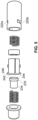
- the valve assembly comprises two main components, a male valve component 202 and a female valve component 204.
- the female component 202 forms a hollow cylinder and has grooves 206a and 206b formed in the interior wall of the cylinder.
- the grooves 206a and 206b are configured to receive tongues 208a and 208b respectively and grooves 206 and tongues 208 cooperate to guide the male component 202 into engagement with the female component 204 through cavity 212.
- the exterior wall 210 of the male component 202 is slideably engaged with the interior wall of the hollow cylinder forming the female component 204 other than in the region of wall 210 comprising groove 209.
- the male component 202 comprises a flange 214 formed to provide a convenient abutment of two parts, 202a and 202b, of the male component 202 which are manufactured as separate units to allow for assembly of the other elements of the male components 202 as will be evident from the later description.
- the female component 204 also includes slots 220a and 220b which are in respective communication with grooves 206a and 206b to receive tongues 208a and 208b respectively.
- Slots 220 extend in a circumferential direction and are shaped to provide a locking function by having a barrier around which a tongue may be moved against a bias. When the tongue has been moved around the barrier the bias returns it to a position in the slot such that the barrier inhibits the tongue returning back through the slot thereby inhibiting a twisting or rotational motion of the male and female components one with respect to the other.
- male component 202 comprises plunger guide 210 (As used herein, the terms plunger guide and exterior wall are used interchangeably) and an end cap 230.
- the plunger guide 210 has a flange 114b and end cap 230 has a flange 114a which facilitates joining respective parts, plunger guide 210 and end cap 230, together.
- a helical coil spring 232 is inserted into the end cap 230 and a plunger 234 extends through the middle of helical coil spring 232 so that a shoulder 235 on the plunger 234 may contact end 232a of the spring 232.
- the plunger 234 is inserted into the hollow cylindrical cavity 236 of the plunger guide 210 of the male component.
- the respective parts of male component 202 may then be assembled.
- Female component 204 comprises a main hollow cylinder 229, a collar 238 and second helical coil spring 240.
- the collar 238 and spring 240 are slideably insertable into the cavity 212 of the hollow cylinder 229 of the female component 204.
- a stopper 241 protrudes from an end of cylinder 229 distal from the end into which the spring 240 and collar 238 are inserted into the cylinder 229.
- the spring fits around stopper 241 and the distal end, 243, of the spring engages with an end wall (not shown) of the cylinder 229 of the female component 204.
- the proximal end, 245, of spring 240 engages with collar 238.
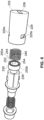
- Figure 5 is an illustration of an exploded view of the valve assembly from another aspect showing plunger 234 and details of the shoulder 235.
- Shoulder 235 includes an engagement surface 242, a neck 244 extending from the engagement surface and plunger head 246.
- FIG. 6 An exploded view of the valve assembly from a yet another aspect is illustrated in figure 6 and shows details of collar 238.
- Collar 238 comprises a cylindrical groove 254 which on an inner wall 252 supports diametrically opposed catch members 250a and 250b.
- Distal end 245 of spring 240 is configured to be insertable into groove 254 and abut against the end wall 239 of collar 238.
- Hollow cylinder 229 is also shown having an end wall 255 with a cavity 256 which forms a pathway for liquid into the interior of cylinder 229.
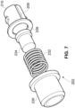
- Figure 7 is a simple illustration showing that plunger 234 fits into the middle of spring 232 which itself fits into end cap 230. Plunger 234 is also shown as fitting into the cavity 236 of plunger guide 210 of the male component 202.
- figure 8 is a simple illustration which in this case shows that spring 240 fits into cavity 212 of the cylinder 229 of female component 204 and collar 238 fits over the end of spring 240 and into cavity 212. A catch member 250a is also partially visible in the figure.
- Figure 9 illustrates the female component 204 from another perspective clearly showing that the distal end 245 of spring 240 fits into groove 254.
- Catch member 250b is also partially visible.
- end wall 255 and cavity 256 Also partially visible is a strut 257 which extends from end wall 255 to support stopper 241 (not shown). As can be seen, strut 257 does not extend to the inner side wall of cylinder 229 thereby providing a pathway for liquid from the interior of cylinder 229 to cavity 256.
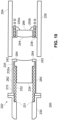
- FIG 10 a schematic illustration of a cross-section of valve assembly 200 prior to coupling respective male and female components together shows further respective male and female components assembled and ready for coupling together.
- Male component 202 has the plunger guide 210 and end cap connected together and spring 232 is compressed such that one end, 232a, abuts shoulder 235 of plunger 234 and the other end abuts an interior formation 231 of the male component 202, in the illustrated case a formation on end cap 230.
- the compression of spring 232 causes the engagement surface 242 of plunger 234 to be biased against and abut partially inwardly extending portion 264 of the plunger guide 210 side wall.
- the outer side wall 262 of plunger guide 210 is configured to be in slidable engagement with the inner wall of cylinder 229 when inserted into the female component 202. Also shown is a thinner section 260 of the side wall 262 which forms the bottom of groove 209 illustrated in previous figures.
- the female component 204 is assembled and the catch members 250a and 250b of collar 238 are urged into abutment against the rear wall 266 of stopper 241 by biasing action of spring 240 which is entrapped in a structure not visible in the illustrated cross-section.
- the cross-section view illustrated in figure 10 is also from an aspect which does not show the strut 257 extending from the end wall 255 (also not shown) and supporting the stopper 241.
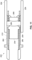
- Figure 11 is a schematic illustration of the male component 202 partially inserted into the female component 202.
- the slidable engagement of plunger guide 210 outer side wall 262 with the inner wall 268 of cylinder 229 is clearly illustrated. Additionally, groove 209 can be seen to be in the process of being formed between the thinner section 260 of the plunger guide wall and the corresponding part of the inner wall of cylinder 229.
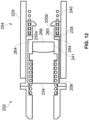
- Figure 12 is a schematic illustration on the male component and female component fully engaged with each other.
- the travel of plunger guide into the cylinder 229 has caused the inwardly extending wall portion 264 to engage with collar 238 and force it back against spring 240.
- groove 209 extends along the inwardly extending wall 264 in the region 265 to form a gas pathway from groove 209 into the interior of cylinder 229.
- the gas pathway 265/209 provides a venting mechanism for air to escape from a reservoir being filled with a liquid but also may provide for the ingress of air into a bottle from which the liquid is being supplied to the reservoir.
- Stopper 241 engages with plunger 234 to prevent it travelling with the plunger guide 210 and forces it back against spring 232 to open a gap between the male component 202 and the female component 204 thereby opening both the valve element of the male component 202 and the valve element of the female component 204 to provide a liquid pathway between the male and female components.
- end wall 255 extends inwardly to form strut 257.
- Strut 257 is not of continuous tubular form but is discontinuous to allow a liquid to pass around stopper 241 into cavity 256.
- Figure 14 illustrates the locking/coupling arrangement between the male component 202 and female component 204 with reference to slot 220a in an intermediate stage just prior to full locking.
- slot 220a includes a barrier portion 270a.
- tongue 208a travels through guide 206a to slot 220a.
- the material of cylinder 229 and/or tongues 208 and/or plunger guide 210 may be resiliently deformable, for example the material may be a suitable plastics material.
- the tongues 208 may be movably biased away from the outer wall of the plunger guide.
- valve assembly for dispensing liquid from a bottle into the reservoir of an electronic smoking device is illustrated in cross-section.
- the male component 202 of the valve assembly is disposed in the neck of a liquid dispenser bottle 274.
- the female component 204 of the valve assembly is disposed in the reservoir of a smoking-substitute device, e.g. e-cigarette, 276.
- Respective male and female components 202 and 204 are respectively fitted to the neck of dispenser bottle 274 and inlet to the reservoir of the smoking device 276. Before insertion respective valve elements of male and female components 202 and 204 are closed.
- FIG 17 is an illustration of the arrangement of figure 16 but from a different aspect that shows the strut supporting the stopper 241.
- the slidable fit between the male and female components 202 and 204 is configured to inhibit flow of liquid and so should be too narrow to encourage a capillary action to draw a liquid between the interface of the outer wall 262 of the male component 202 and the inner wall of the cylinder 229 of the female component 204.
- it is not a so-called interference fit but a transitional fit permitting close slidable engagement yet inhibits the flow of liquid.
- a smoking-substitute device and refilling apparatus for a substitute-smoking device that avoids or at least ameliorates the problems of the prior art and that addresses the statutory legal requirements that will shortly be implemented in certain markets. More particularly, there is disclosed one or more embodiments of a smoking-substitute device and smoking-substitute device refill apparatus that permits the refilling of a reservoir from a dispenser without, or at least with reduced, leakage or spillage.
- any reference to "one embodiment” or “an embodiment” means that a particular element, feature, structure, or characteristic described in connection with the embodiment is included in at least one embodiment.
- the appearances of the phrase “in one embodiment” or the phrase “in an embodiment” in various places in the specification are not necessarily all referring to the same embodiment.
- the terms “comprises,” “comprising,” “includes,” “including,” “has,” “having” or any other variation thereof, are intended to cover a non-exclusive inclusion.
- a process, method, article, or apparatus that comprises a list of elements is not necessarily limited to only those elements but may include other elements not expressly listed or inherent to such process, method, article, or apparatus.
- “or” refers to an inclusive or and not to an exclusive or. For example, a condition A or B is satisfied by any one of the following: A is true (or present) and B is false (or not present), A is false (or not present) and B is true (or present), and both A and B are true (or present).
- helical coil spring 232 has an end distal from the plunger abutting an interior formation 231 of the end cap 230.
- that end of spring 232 may abut the end wall of end cap 230.
Landscapes
- Engineering & Computer Science (AREA)
- Mechanical Engineering (AREA)
- Health & Medical Sciences (AREA)
- General Health & Medical Sciences (AREA)
- Veterinary Medicine (AREA)
- Public Health (AREA)
- Anesthesiology (AREA)
- Biomedical Technology (AREA)
- Heart & Thoracic Surgery (AREA)
- Hematology (AREA)
- Life Sciences & Earth Sciences (AREA)
- Animal Behavior & Ethology (AREA)
- Pulmonology (AREA)
- Bioinformatics & Cheminformatics (AREA)
- Ceramic Engineering (AREA)
- Chemical & Material Sciences (AREA)
- Dispersion Chemistry (AREA)
- Containers And Packaging Bodies Having A Special Means To Remove Contents (AREA)
- Basic Packing Technique (AREA)
- Filling Or Discharging Of Gas Storage Vessels (AREA)
- Catching Or Destruction (AREA)
- Quick-Acting Or Multi-Walled Pipe Joints (AREA)
Claims (8)
- Système comprenant un distributeur de recharge (274), un réservoir d'un dispositif de substitution au tabac (276) et un liquide, le système étant conçu et configuré pour transférer ledit liquide entre ledit distributeur de recharge (274) et ledit réservoir du dispositif de substitution au tabac (276), le système comprenant un ensemble de couplage (200) comprenant un composant mâle (202) et un composant femelle (204) et étant assemblé en insérant au moins partiellement ledit composant mâle (202) dans ledit composant femelle (204) avec un ajustement coulissant en recevant une languette (208a, 208b) du composant mâle (202) dans une rainure de guidage (206) du composant femelle (204),dans lequel le composant mâle (202) comprend :une paroi extérieure (210) définissant un passage de liquide,une rainure (209) dans la paroi extérieure (210) formant un passage de gaz pour fournir un mécanisme de ventilation pour que de l'air s'échappe du réservoir, etla languette (208a, 208b) sur la paroi extérieure (210),dans lequel le composant femelle (204) comprend :un cylindre creux (229) incluant une paroi intérieure configurée pour faciliter l'engagement coulissant de la paroi extérieure (210) du composant mâle (202),la rainure de guidage (206) formée dans la paroi intérieure du cylindre creux (229), configurée pour recevoir la languette (208a, 208b) du composant mâle (202), guidant ainsi l'engagement du composant mâle (202) avec le composant femelle (204), etune fente (220) dans le cylindre creux (229) de l'élément femelle (204),dans lequel le composant mâle (202) est configuré pour être assemblé avec le composant femelle (204) en insérant au moins partiellement la paroi extérieure (210) dudit composant mâle (202) dans la paroi intérieure du cylindre creux (229) dudit composant femelle (204) avec un ajustement coulissant en insérant la languette (208a, 208b) dans la rainure de guidage (206) du composant femelle (204),dans lequel la languette (208a, 208b) peut également être insérée dans la fente (220) dans le cylindre creux (229) du composant femelle (204), facilitant ainsi un mouvement coulissant entre une position non sécurisée et fermée et une position sécurisée et ouverte, etdans lequel ledit ensemble (200) est engagé en étant coulissant entre la position non sécurisée et fermée dans laquelle la communication de liquide à travers le passage de liquide est restreinte entre une sortie de distributeur et une entrée de réservoir et la communication de gaz à travers le passage de gaz est restreinte vers une sortie de réservoir et une entrée de distributeur, et la position sécurisée et ouverte dans laquelle ledit ensemble (200) ouvre une communication de liquide à travers le passage de liquide entre la sortie de distributeur et l'entrée de réservoir et ouvre une communication de gaz à travers le passage de gaz vers la sortie de réservoir,dans lequel ledit ensemble (200) ouvre simultanément ledit passage de communication de liquide entre ledit distributeur (274) et ledit réservoir à travers la sortie de distributeur et l'entrée de réservoir et ledit passage de communication de gaz entre ledit réservoir et un parmi ledit distributeur (274) et l'atmosphère à travers ladite sortie de réservoir et l'entrée de distributeur.
- Système selon la revendication 1, dans lequel l'ensemble de couplage (200) est adapté pour fermer à la fois le passage de communication de liquide et le passage de communication de gaz lorsqu'il est éloigné de la position sécurisée pour désengager le distributeur et le réservoir.
- Système selon la revendication 1, dans lequel, dans la position ouverte, le système est apte à permettre le transfert de liquide à travers le passage de communication de liquide, et l'expulsion d'un volume essentiellement équivalent de gaz à travers le passage de communication de gaz.
- Système selon la revendication 3, dans lequel, dans la position ouverte, le système est adapté pour maintenir une pression essentiellement égale dans le distributeur (274) et le réservoir.
- Système selon l'une quelconque des revendications précédentes, dans lequel ladite sortie de distributeur comprend une vanne qui peut être actionnée lorsque l'ensemble de couplage (200) est sécurisé dans la position ouverte pour ouvrir ledit passage de communication de liquide entre ledit distributeur (274) et ledit réservoir.
- Système selon la revendication 1, dans lequel ladite sortie de réservoir comprend une vanne qui peut être actionnée lorsque l'ensemble de couplage (200) est sécurisé dans la position ouverte pour ouvrir ledit passage de communication de gaz entre ledit réservoir et le distributeur (274).
- Système selon la revendication 6, dans lequel la vanne est sollicitée pour fermer le passage de communication de gaz lorsque l'ensemble de couplage (200) n'est pas sécurisé dans la position ouverte.
- Système selon l'une quelconque des revendications précédentes, dans lequel l'ensemble de couplage (200) comprend un ensemble de guidage pour guider le mouvement de la sortie de distributeur dans la position sécurisée et ouverte.
Applications Claiming Priority (4)
| Application Number | Priority Date | Filing Date | Title |
|---|---|---|---|
| GB1502492.0A GB2535982A (en) | 2015-02-13 | 2015-02-13 | System and apparatus |
| GB1505216.0A GB2535239A (en) | 2015-02-13 | 2015-03-26 | System and apparatus |
| GB1601096.9A GB2536117A (en) | 2015-02-13 | 2016-01-20 | System and assembly |
| PCT/GB2016/050282 WO2016128717A1 (fr) | 2015-02-13 | 2016-02-05 | Système et appareil |
Publications (2)
| Publication Number | Publication Date |
|---|---|
| EP3256384A1 EP3256384A1 (fr) | 2017-12-20 |
| EP3256384B1 true EP3256384B1 (fr) | 2024-03-27 |
Family
ID=70005099
Family Applications (1)
| Application Number | Title | Priority Date | Filing Date |
|---|---|---|---|
| EP16703843.9A Active EP3256384B1 (fr) | 2015-02-13 | 2016-02-05 | Système et appareil |
Country Status (10)
| Country | Link |
|---|---|
| US (1) | US11312614B2 (fr) |
| EP (1) | EP3256384B1 (fr) |
| JP (1) | JP6475850B2 (fr) |
| KR (1) | KR102069012B1 (fr) |
| CN (2) | CN107223023B (fr) |
| AU (1) | AU2016217649B2 (fr) |
| CA (1) | CA2975576C (fr) |
| GB (2) | GB2535982A (fr) |
| RU (1) | RU2675657C1 (fr) |
| WO (1) | WO2016128717A1 (fr) |
Families Citing this family (22)
| Publication number | Priority date | Publication date | Assignee | Title |
|---|---|---|---|---|
| DE102015217671B4 (de) * | 2015-09-15 | 2020-12-31 | Fontem Holdings 1 B.V. | Vorrichtung und Verfahren zum Befüllen einer elektrischen Zigarette |
| CN105249535B (zh) * | 2015-09-30 | 2024-03-05 | 深圳市合元科技有限公司 | 注液容器和可重复注液系统以及注液方法 |
| US10015989B2 (en) * | 2016-01-27 | 2018-07-10 | Rai Strategic Holdings, Inc. | One-way valve for refilling an aerosol delivery device |
| US11412781B2 (en) * | 2016-02-12 | 2022-08-16 | Rai Strategic Holdings, Inc. | Adapters for refilling an aerosol delivery device |
| EP3298913B1 (fr) | 2016-09-06 | 2020-11-04 | Fontem Holdings 2 B.V. | Boîtier pour un dispositif à fumer électronique |
| CA3046954C (fr) | 2016-12-12 | 2024-01-02 | Vmr Products Llc | Cartouche reutilisable pour vaporisateur |
| WO2018114163A1 (fr) * | 2016-12-23 | 2018-06-28 | Jt International Sa | Système de recharge pour inhalateur d'aérosol |
| US10314340B2 (en) * | 2017-04-21 | 2019-06-11 | Rai Strategic Holdings, Inc. | Refillable aerosol delivery device and related method |
| EP3437496A1 (fr) * | 2017-08-02 | 2019-02-06 | BSMW Limited | Système de bobine hygiénique à remplacement rapide |
| CN110237373B (zh) * | 2018-03-08 | 2023-06-02 | 润生药业有限公司 | 一种生产用于联合用药的药物载体的装置及方法 |
| DE102018208110A1 (de) * | 2018-05-23 | 2019-11-28 | F. Holzer Gmbh | Abgabekopf und Abgabevorrichtung zur dosierten Abgabe flüssiger Präparate sowie Verwendungsmöglichkeiten |
| JP7303832B2 (ja) * | 2018-06-28 | 2023-07-05 | ジェイティー インターナショナル エス.エイ. | 電子喫煙装置、ディスペンサー、喫煙システム、及びタバコムース配合物を供給する方法 |
| WO2020097067A1 (fr) | 2018-11-05 | 2020-05-14 | Juul Labs, Inc. | Cartouches pour dispositifs de vaporisation |
| KR102308830B1 (ko) * | 2019-04-25 | 2021-10-05 | 주식회사 케이티앤지 | 에어로졸 생성 장치 |
| US12096790B2 (en) | 2019-07-04 | 2024-09-24 | Philip Morris Products S.A. | Inductive heating arrangement having an annular channel |
| WO2021211989A1 (fr) * | 2020-04-18 | 2021-10-21 | Benecke Peter Nicholas | Distributeur de boisson à libération rapide avec coupleur à clavette |
| US11925208B2 (en) * | 2020-06-25 | 2024-03-12 | Altria Client Services Llc | Non-nicotine e-vaping device |
| ES2936385B2 (es) * | 2021-09-15 | 2024-03-05 | Radial Italica 3000 S L | Sistema de proteccion de agujas de llenado |
| JP7406267B2 (ja) * | 2022-01-05 | 2023-12-27 | 株式会社ワイ・ジェー・エス. | 接続構造 |
| WO2024047287A1 (fr) * | 2022-08-31 | 2024-03-07 | Gb Developpement | Dispositif distributeur de produit a amorcage ameliore et procede de remplissage associe |
| FR3139126B1 (fr) * | 2022-08-31 | 2026-03-13 | Gb Dev | Dispositif distributeur de produit à amorçage amélioré et procédé de remplissage associé. |
| FR3139124B1 (fr) * | 2022-08-31 | 2026-03-13 | Gb Dev | Dispositif distributeur de produit à amorçage amélioré et procédé de remplissage associé. |
Citations (8)
| Publication number | Priority date | Publication date | Assignee | Title |
|---|---|---|---|---|
| GB2531830A (en) * | 2015-04-01 | 2016-05-04 | Electronic Cigarettes Ltd | Simulated smoking device |
| EP3124430A1 (fr) * | 2015-10-23 | 2017-02-01 | Shenzhen First Union Technology Co., Ltd. | Valve pour conteneur d'injection de liquide |
| EP3129089A1 (fr) * | 2014-04-07 | 2017-02-15 | Intrepid Brands, LLC | Appareil et procédés de distribution d'e-liquide |
| WO2017024926A1 (fr) * | 2015-08-11 | 2017-02-16 | 惠州市吉瑞科技有限公司深圳分公司 | Ensemble d'atomisation |
| WO2017046247A1 (fr) * | 2015-09-15 | 2017-03-23 | Fontem Holdings 1 B.V. | Dispositif et procédé de remplissage d'une cigarette électrique |
| WO2017071298A1 (fr) * | 2015-10-28 | 2017-05-04 | 深圳麦克韦尔股份有限公司 | Flacon de liquide à vapoter et cigarette électronique pouvant être rechargée par l'intermédiaire du flacon de liquide à vapoter |
| EP3254987A1 (fr) * | 2015-09-30 | 2017-12-13 | Shenzhen First Union Technology Co., Ltd. | Dispositif rechargeable |
| EP3348155A1 (fr) * | 2015-10-28 | 2018-07-18 | Shenzhen Smoore Technology Limited | Flacon de liquide à vapoter et cigarette électronique |
Family Cites Families (87)
| Publication number | Priority date | Publication date | Assignee | Title |
|---|---|---|---|---|
| US490915A (en) * | 1893-01-31 | Shoe-rest | ||
| US3125135A (en) | 1964-03-17 | Filling device with detachable flow coupling means | ||
| US437915A (en) * | 1890-10-07 | Third to joseph c | ||
| US692795A (en) * | 1901-03-25 | 1902-02-04 | Handlan Buck Mfg Company | Hose or pipe coupling. |
| US996127A (en) * | 1910-06-09 | 1911-06-27 | Atwood L Boggs | Liquid-cooler. |
| US1890011A (en) * | 1930-05-05 | 1932-12-06 | Wirz Henry | Coupling device |
| US2344739A (en) * | 1942-08-01 | 1944-03-21 | Keller Tool Co | Coupling device |
| US2628850A (en) * | 1949-03-19 | 1953-02-17 | Donald V Summerville | Releasable conduit connection with automatic valving |
| US2907591A (en) * | 1957-10-14 | 1959-10-06 | David E Gulick | Hose coupling having bayonet type joining means |
| GB921899A (en) * | 1960-05-18 | 1963-03-27 | Colibri Lighters | Improvements relating to gas-burning cigarette lighters and fuel refill containers for use with such lighters |
| US3005475A (en) * | 1960-06-13 | 1961-10-24 | Jr Richard W Beall | Combined liquid dispensing and air venting apparatus |
| US3033247A (en) * | 1961-09-11 | 1962-05-08 | Linden H Chandler | Vented non-drip liquid dispensing device |
| US3540402A (en) * | 1968-10-29 | 1970-11-17 | Parker Hannifin Corp | Liquid dispensing device |
| FR2034123A1 (fr) * | 1969-02-07 | 1970-12-11 | Quercia Flaminaire | |
| GB1579283A (en) | 1977-03-04 | 1980-11-19 | Warner Lambert Co | Single unit liquid container fur use in a single unit dose pharmaceutical delivery system |
| US4176694A (en) * | 1978-03-27 | 1979-12-04 | Donald R. Dickerson | Automatic shutoff liquid dispensing valve |
| US4699188A (en) * | 1986-01-17 | 1987-10-13 | Baker Henry E | Hygienic liquid dispensing system |
| US5249611A (en) | 1987-03-16 | 1993-10-05 | Vemco, Inc. | Pour spout |
| US4758023A (en) * | 1987-05-14 | 1988-07-19 | The Singer Company | Removable connection assembly |
| US5058636A (en) | 1988-06-27 | 1991-10-22 | Link Research & Development, Inc. | Liquid flow controlling system |
| DE3836489A1 (de) * | 1988-10-26 | 1990-05-03 | Kronseder Maschf Krones | Verfahren und vorrichtung zum befuellen von getraenkedosen |
| JP2843349B2 (ja) * | 1989-02-03 | 1999-01-06 | オーバル機器工業株式会社 | フレキシブルバッグの自動空気抜き装置及びカップラの自動着脱装置 |
| US5088774A (en) * | 1990-05-07 | 1992-02-18 | Tylan General, Inc. | Coupling for interconnection of coaxial tubing |
| US5465875A (en) * | 1990-11-20 | 1995-11-14 | Wisdom Agricultural Investment Limited | Closed transfer devices for agricultural chemicals and the like |
| US5234038A (en) * | 1991-09-27 | 1993-08-10 | Briggs & Stratton Corporation | Pour spout |
| US5628352A (en) * | 1992-07-24 | 1997-05-13 | Briggs & Stratton Corporation | Closable pour spout for fluid dispensing container |
| DE4231635C2 (de) * | 1992-09-22 | 1994-07-28 | Schaefer Werke Gmbh | Behälter zur Aufbewahrung und zum Transport von fließfähigen Medien, vornehmlich von Flüssigkeiten |
| DE4414697C2 (de) * | 1994-04-27 | 1998-06-18 | Caremed Vertriebsgesellschaft | Vorrichtung zum Transferieren und Entnehmen von Flüssigkeiten aus Flaschen, Beuteln oder ähnlichen Behältnissen für medizinische Zwecke |
| US5507326A (en) * | 1994-08-05 | 1996-04-16 | Scully Signal Company | Fluid overfill protection and product identification system |
| US5560522A (en) * | 1995-04-25 | 1996-10-01 | Clark; Robert D. | Push opened valve for dispensing liquids |
| US6322207B1 (en) | 1995-04-27 | 2001-11-27 | Hewlett-Packard Company | Replaceable pump module for receiving replaceable ink supplies to provide ink to an ink jet printing system |
| US6086561A (en) * | 1995-05-01 | 2000-07-11 | Science Incorporated | Fluid delivery apparatus with reservoir fill assembly |
| US6079823A (en) * | 1997-07-23 | 2000-06-27 | Marconi Data Systems Inc. | Ink bottle with puncturable diaphragm closure |
| US5890517A (en) * | 1997-11-04 | 1999-04-06 | Laible; Rodney | Vented quick disconnect coupling |
| JP2000025779A (ja) | 1998-07-13 | 2000-01-25 | Toyo Eng Corp | 空気導入管付きバルブ及び使用方法 |
| AUPP600398A0 (en) * | 1998-09-17 | 1998-10-08 | Kilian, Michael | Dispensing lid |
| FR2798368B1 (fr) | 1999-09-09 | 2001-11-23 | Valois Sa | Pompe de distribution de produit fluide amelioree, et dispositif de distribution de produit fluide comportant une telle pompe |
| US6155464A (en) * | 1999-09-13 | 2000-12-05 | Dsd International Inc. | Non-spilling detachable pouring spout |
| US6544246B1 (en) * | 2000-01-24 | 2003-04-08 | Bracco Diagnostics, Inc. | Vial access adapter and vial combination |
| US6637430B1 (en) | 2000-06-16 | 2003-10-28 | Ponwell Enterprises Limited | Respiratory delivery system with power/medicament recharge assembly |
| FR2810301B1 (fr) | 2000-06-16 | 2002-09-13 | Rexam Sofab | Dispositif de reprise d'air statique pour distributeur de produit liquide |
| US6378742B1 (en) * | 2000-10-10 | 2002-04-30 | Rieke Corporation | Fluid dispensing closure |
| NL1016714C2 (nl) * | 2000-11-27 | 2002-06-06 | Afa Polytek Bv | Doseerinrichting en werkwijze voor het vullen daarvan. |
| US6581851B1 (en) * | 2001-04-25 | 2003-06-24 | Michael J. Murphy | Vapor recovery nozzle |
| US6715520B2 (en) * | 2001-10-11 | 2004-04-06 | Carmel Pharma Ab | Method and assembly for fluid transfer |
| US6691738B2 (en) * | 2001-11-21 | 2004-02-17 | Taiwan Semiconductor Manufacturing Co., Ltd. | Filler for airtight container |
| US6889732B2 (en) * | 2002-08-12 | 2005-05-10 | Clifford Harry Allen | No-spill, vapor-recovery, container spout |
| US7086431B2 (en) * | 2002-12-09 | 2006-08-08 | D'antonio Consultants International, Inc. | Injection cartridge filling apparatus |
| US6786427B2 (en) | 2002-12-19 | 2004-09-07 | S. C. Johnson & Son, Inc. | Liquid sealing arrangements for replaceable liquid reservoirs |
| US6938650B2 (en) * | 2003-11-26 | 2005-09-06 | Private Brand Tools (Australia) Pty Ltd | Filling apparatus |
| GB0402693D0 (en) * | 2004-02-06 | 2004-03-10 | Glaxo Group Ltd | A fluid dispenser |
| AT500874B1 (de) * | 2004-03-05 | 2006-11-15 | Hagleitner Hans Georg | Ausgabeventil |
| FR2880879B1 (fr) * | 2005-01-20 | 2007-02-16 | Techpack Int Sa | Dispositif de recharge pour distribuer un produit cosmetique |
| CA2545907C (fr) | 2006-05-05 | 2014-01-28 | Roger B. Nielsen | Bec autoventile a fermer |
| GB0712305D0 (en) | 2007-06-25 | 2007-08-01 | Kind Group Ltd | A system comprising a simulated cigarette device and a refill unit |
| US8123082B2 (en) | 2008-01-22 | 2012-02-28 | McNeil-AB | Hand-held dispensing device |
| GB0808154D0 (en) | 2008-05-06 | 2008-06-11 | British American Tobacco Co | Aerosol dispensing device |
| US20110084474A1 (en) * | 2008-06-25 | 2011-04-14 | Paden David B | High retention magnetic coupling device for conduit attachment |
| US8141601B2 (en) * | 2008-10-02 | 2012-03-27 | Roche Diagnostics Operations, Inc. | Manual filling aid with push button fill |
| GB0820981D0 (en) | 2008-11-17 | 2008-12-24 | Reckitt & Colman Overseas | Dispenser and refill unit |
| AU2010236426B2 (en) * | 2009-04-14 | 2013-08-29 | Yukon Medical, Llc | Fluid transfer device |
| US9402787B2 (en) * | 2010-02-01 | 2016-08-02 | Medmix Systems Ag | Device for removing a fluid from a vial |
| US8684994B2 (en) * | 2010-02-24 | 2014-04-01 | Medimop Medical Projects Ltd. | Fluid transfer assembly with venting arrangement |
| WO2011139921A2 (fr) * | 2010-04-29 | 2011-11-10 | Yukon Medical, Llc | Dispositif de distribution et de transfert de fluide dans plusieurs récipients |
| US20110272938A1 (en) * | 2010-05-04 | 2011-11-10 | Ming-Shuan Lin | Fast connecting tube module |
| US8757169B2 (en) | 2010-12-29 | 2014-06-24 | David Gysland | Electronic cigarette refilling apparatus |
| DE102011009745B4 (de) | 2011-01-28 | 2012-09-13 | Kautex Textron Gmbh & Co. Kg | Einfüllstutzen für einen Nebenflüssigkeitsbehälter |
| FR2972723B1 (fr) * | 2011-03-14 | 2013-03-15 | Techniplast | Dispositif de remplissage d'un flacon |
| FR2974074B1 (fr) * | 2011-04-14 | 2014-07-04 | Valois Sas | Systeme de recharge de produit fluide. |
| NL2007552C2 (en) * | 2011-10-07 | 2013-04-09 | Andries Valk | Coupling device, line path and line end section. |
| AU2012347294B2 (en) * | 2011-12-08 | 2017-12-07 | Philip Morris Products S.A. | An aerosol generating device with air flow nozzles |
| FR2996828B1 (fr) * | 2012-10-15 | 2014-10-24 | Rexam Dispensing Sys | Flacon remplissable de distribution d’un produit fluide |
| GB2512326B (en) * | 2013-03-26 | 2016-02-24 | Kind Consumer Ltd | A pressurised refill canister with an outlet valve |
| JP2016515392A (ja) | 2013-04-10 | 2016-05-30 | シノ ビジネス リミテッド | 電子喫煙代用装置 |
| ES2784206T3 (es) * | 2013-06-03 | 2020-09-23 | Old Navigators Ltd | Kit para inhalar sustancias vaporizadas |
| FR3007005B1 (fr) * | 2013-06-14 | 2015-12-18 | Aptar France Sas | Reservoir de produit fluide rechargeable par gravite. |
| AU2014311259B2 (en) * | 2013-08-27 | 2020-05-21 | Twist4Lock Pty Ltd As Trustee Of The T4L Trust | System and method of releasably connecting pipe sections |
| FR3012427B1 (fr) * | 2013-10-24 | 2016-01-01 | Maitrise Et Innovation | Dispositif de recharge de recipient |
| US10292424B2 (en) * | 2013-10-31 | 2019-05-21 | Rai Strategic Holdings, Inc. | Aerosol delivery device including a pressure-based aerosol delivery mechanism |
| US9414991B2 (en) * | 2013-11-06 | 2016-08-16 | Becton Dickinson and Company Limited | Medical connector having locking engagement |
| CN203646503U (zh) * | 2013-11-29 | 2014-06-18 | 刘秋明 | 一种电子烟装置 |
| US10709173B2 (en) * | 2014-02-06 | 2020-07-14 | Juul Labs, Inc. | Vaporizer apparatus |
| WO2015127338A1 (fr) * | 2014-02-24 | 2015-08-27 | Gojo Industries, Inc. | Récipients non repliables mis à l'air libre, récipients de re-remplissage rechargeables, distributeurs et unités de re-remplissage |
| US20170064997A1 (en) * | 2014-02-28 | 2017-03-09 | Beyond Twenty Ltd. | Electronic vaporiser system |
| US10588176B2 (en) * | 2014-02-28 | 2020-03-10 | Ayr Ltd. | Electronic vaporiser system |
| GB2524296B (en) | 2014-03-19 | 2018-10-24 | Kind Consumer Ltd | An inhaler |
| US20160332754A1 (en) | 2015-05-13 | 2016-11-17 | Fontem Holdings 4 B.V. | Device for refilling electronic cigarette cartridge |
-
2015
- 2015-02-13 GB GB1502492.0A patent/GB2535982A/en not_active Withdrawn
-
2016
- 2016-01-20 GB GB1601096.9A patent/GB2536117A/en not_active Withdrawn
- 2016-02-05 RU RU2017128299A patent/RU2675657C1/ru active
- 2016-02-05 US US15/550,740 patent/US11312614B2/en active Active
- 2016-02-05 AU AU2016217649A patent/AU2016217649B2/en not_active Ceased
- 2016-02-05 CN CN201680010145.7A patent/CN107223023B/zh not_active Expired - Fee Related
- 2016-02-05 CA CA2975576A patent/CA2975576C/fr active Active
- 2016-02-05 WO PCT/GB2016/050282 patent/WO2016128717A1/fr not_active Ceased
- 2016-02-05 KR KR1020177025638A patent/KR102069012B1/ko not_active Expired - Fee Related
- 2016-02-05 EP EP16703843.9A patent/EP3256384B1/fr active Active
- 2016-02-05 JP JP2017542040A patent/JP6475850B2/ja not_active Expired - Fee Related
- 2016-02-06 CN CN201620118731.0U patent/CN205953490U/zh not_active Expired - Lifetime
Patent Citations (8)
| Publication number | Priority date | Publication date | Assignee | Title |
|---|---|---|---|---|
| EP3129089A1 (fr) * | 2014-04-07 | 2017-02-15 | Intrepid Brands, LLC | Appareil et procédés de distribution d'e-liquide |
| GB2531830A (en) * | 2015-04-01 | 2016-05-04 | Electronic Cigarettes Ltd | Simulated smoking device |
| WO2017024926A1 (fr) * | 2015-08-11 | 2017-02-16 | 惠州市吉瑞科技有限公司深圳分公司 | Ensemble d'atomisation |
| WO2017046247A1 (fr) * | 2015-09-15 | 2017-03-23 | Fontem Holdings 1 B.V. | Dispositif et procédé de remplissage d'une cigarette électrique |
| EP3254987A1 (fr) * | 2015-09-30 | 2017-12-13 | Shenzhen First Union Technology Co., Ltd. | Dispositif rechargeable |
| EP3124430A1 (fr) * | 2015-10-23 | 2017-02-01 | Shenzhen First Union Technology Co., Ltd. | Valve pour conteneur d'injection de liquide |
| WO2017071298A1 (fr) * | 2015-10-28 | 2017-05-04 | 深圳麦克韦尔股份有限公司 | Flacon de liquide à vapoter et cigarette électronique pouvant être rechargée par l'intermédiaire du flacon de liquide à vapoter |
| EP3348155A1 (fr) * | 2015-10-28 | 2018-07-18 | Shenzhen Smoore Technology Limited | Flacon de liquide à vapoter et cigarette électronique |
Also Published As
| Publication number | Publication date |
|---|---|
| US11312614B2 (en) | 2022-04-26 |
| JP6475850B2 (ja) | 2019-02-27 |
| KR20170137058A (ko) | 2017-12-12 |
| GB2535982A (en) | 2016-09-07 |
| CA2975576A1 (fr) | 2016-08-18 |
| WO2016128717A1 (fr) | 2016-08-18 |
| JP2018513059A (ja) | 2018-05-24 |
| AU2016217649A1 (en) | 2017-08-24 |
| CN107223023B (zh) | 2020-08-14 |
| CA2975576C (fr) | 2020-09-22 |
| GB2536117A (en) | 2016-09-07 |
| GB201502492D0 (en) | 2015-04-01 |
| EP3256384A1 (fr) | 2017-12-20 |
| GB201601096D0 (en) | 2016-03-02 |
| CN205953490U (zh) | 2017-02-15 |
| US20180044162A1 (en) | 2018-02-15 |
| KR102069012B1 (ko) | 2020-02-11 |
| AU2016217649B2 (en) | 2018-11-08 |
| RU2675657C1 (ru) | 2018-12-21 |
| CN107223023A (zh) | 2017-09-29 |
Similar Documents
| Publication | Publication Date | Title |
|---|---|---|
| EP3256384B1 (fr) | Système et appareil | |
| US11197502B2 (en) | System and assembly for refilling a liquid reservoir | |
| US11111127B2 (en) | System and apparatus | |
| US11224706B2 (en) | Dispenser | |
| HK1237602A (en) | Dispenser | |
| HK1237602A1 (en) | Dispenser | |
| HK1237604A1 (en) | Dispenser | |
| HK1237604A (en) | Dispenser |
Legal Events
| Date | Code | Title | Description |
|---|---|---|---|
| STAA | Information on the status of an ep patent application or granted ep patent |
Free format text: STATUS: THE INTERNATIONAL PUBLICATION HAS BEEN MADE |
|
| PUAI | Public reference made under article 153(3) epc to a published international application that has entered the european phase |
Free format text: ORIGINAL CODE: 0009012 |
|
| STAA | Information on the status of an ep patent application or granted ep patent |
Free format text: STATUS: REQUEST FOR EXAMINATION WAS MADE |
|
| 17P | Request for examination filed |
Effective date: 20170913 |
|
| AK | Designated contracting states |
Kind code of ref document: A1 Designated state(s): AL AT BE BG CH CY CZ DE DK EE ES FI FR GB GR HR HU IE IS IT LI LT LU LV MC MK MT NL NO PL PT RO RS SE SI SK SM TR |
|
| AX | Request for extension of the european patent |
Extension state: BA ME |
|
| DAV | Request for validation of the european patent (deleted) | ||
| DAX | Request for extension of the european patent (deleted) | ||
| REG | Reference to a national code |
Ref country code: HK Ref legal event code: DE Ref document number: 1242664 Country of ref document: HK |
|
| STAA | Information on the status of an ep patent application or granted ep patent |
Free format text: STATUS: EXAMINATION IS IN PROGRESS |
|
| 17Q | First examination report despatched |
Effective date: 20190214 |
|
| GRAP | Despatch of communication of intention to grant a patent |
Free format text: ORIGINAL CODE: EPIDOSNIGR1 |
|
| STAA | Information on the status of an ep patent application or granted ep patent |
Free format text: STATUS: GRANT OF PATENT IS INTENDED |
|
| RAP1 | Party data changed (applicant data changed or rights of an application transferred) |
Owner name: FONTEM VENTURES B.V. |
|
| INTG | Intention to grant announced |
Effective date: 20231024 |
|
| GRAS | Grant fee paid |
Free format text: ORIGINAL CODE: EPIDOSNIGR3 |
|
| GRAA | (expected) grant |
Free format text: ORIGINAL CODE: 0009210 |
|
| STAA | Information on the status of an ep patent application or granted ep patent |
Free format text: STATUS: THE PATENT HAS BEEN GRANTED |
|
| AK | Designated contracting states |
Kind code of ref document: B1 Designated state(s): AL AT BE BG CH CY CZ DE DK EE ES FI FR GB GR HR HU IE IS IT LI LT LU LV MC MK MT NL NO PL PT RO RS SE SI SK SM TR |
|
| REG | Reference to a national code |
Ref country code: GB Ref legal event code: FG4D |
|
| REG | Reference to a national code |
Ref country code: CH Ref legal event code: EP |
|
| REG | Reference to a national code |
Ref country code: DE Ref legal event code: R096 Ref document number: 602016086529 Country of ref document: DE |
|
| REG | Reference to a national code |
Ref country code: IE Ref legal event code: FG4D |
|
| PG25 | Lapsed in a contracting state [announced via postgrant information from national office to epo] |
Ref country code: LT Free format text: LAPSE BECAUSE OF FAILURE TO SUBMIT A TRANSLATION OF THE DESCRIPTION OR TO PAY THE FEE WITHIN THE PRESCRIBED TIME-LIMIT Effective date: 20240327 |
|
| REG | Reference to a national code |
Ref country code: LT Ref legal event code: MG9D |
|
| PG25 | Lapsed in a contracting state [announced via postgrant information from national office to epo] |
Ref country code: GR Free format text: LAPSE BECAUSE OF FAILURE TO SUBMIT A TRANSLATION OF THE DESCRIPTION OR TO PAY THE FEE WITHIN THE PRESCRIBED TIME-LIMIT Effective date: 20240628 |
|
| PG25 | Lapsed in a contracting state [announced via postgrant information from national office to epo] |
Ref country code: RS Free format text: LAPSE BECAUSE OF FAILURE TO SUBMIT A TRANSLATION OF THE DESCRIPTION OR TO PAY THE FEE WITHIN THE PRESCRIBED TIME-LIMIT Effective date: 20240627 Ref country code: HR Free format text: LAPSE BECAUSE OF FAILURE TO SUBMIT A TRANSLATION OF THE DESCRIPTION OR TO PAY THE FEE WITHIN THE PRESCRIBED TIME-LIMIT Effective date: 20240327 |
|
| PG25 | Lapsed in a contracting state [announced via postgrant information from national office to epo] |
Ref country code: RS Free format text: LAPSE BECAUSE OF FAILURE TO SUBMIT A TRANSLATION OF THE DESCRIPTION OR TO PAY THE FEE WITHIN THE PRESCRIBED TIME-LIMIT Effective date: 20240627 Ref country code: NO Free format text: LAPSE BECAUSE OF FAILURE TO SUBMIT A TRANSLATION OF THE DESCRIPTION OR TO PAY THE FEE WITHIN THE PRESCRIBED TIME-LIMIT Effective date: 20240627 Ref country code: LT Free format text: LAPSE BECAUSE OF FAILURE TO SUBMIT A TRANSLATION OF THE DESCRIPTION OR TO PAY THE FEE WITHIN THE PRESCRIBED TIME-LIMIT Effective date: 20240327 Ref country code: HR Free format text: LAPSE BECAUSE OF FAILURE TO SUBMIT A TRANSLATION OF THE DESCRIPTION OR TO PAY THE FEE WITHIN THE PRESCRIBED TIME-LIMIT Effective date: 20240327 Ref country code: GR Free format text: LAPSE BECAUSE OF FAILURE TO SUBMIT A TRANSLATION OF THE DESCRIPTION OR TO PAY THE FEE WITHIN THE PRESCRIBED TIME-LIMIT Effective date: 20240628 Ref country code: FI Free format text: LAPSE BECAUSE OF FAILURE TO SUBMIT A TRANSLATION OF THE DESCRIPTION OR TO PAY THE FEE WITHIN THE PRESCRIBED TIME-LIMIT Effective date: 20240327 Ref country code: BG Free format text: LAPSE BECAUSE OF FAILURE TO SUBMIT A TRANSLATION OF THE DESCRIPTION OR TO PAY THE FEE WITHIN THE PRESCRIBED TIME-LIMIT Effective date: 20240327 |
|
| REG | Reference to a national code |
Ref country code: NL Ref legal event code: MP Effective date: 20240327 |
|
| PG25 | Lapsed in a contracting state [announced via postgrant information from national office to epo] |
Ref country code: SE Free format text: LAPSE BECAUSE OF FAILURE TO SUBMIT A TRANSLATION OF THE DESCRIPTION OR TO PAY THE FEE WITHIN THE PRESCRIBED TIME-LIMIT Effective date: 20240327 Ref country code: LV Free format text: LAPSE BECAUSE OF FAILURE TO SUBMIT A TRANSLATION OF THE DESCRIPTION OR TO PAY THE FEE WITHIN THE PRESCRIBED TIME-LIMIT Effective date: 20240327 |
|
| REG | Reference to a national code |
Ref country code: HK Ref legal event code: WD Ref document number: 1242664 Country of ref document: HK |
|
| PG25 | Lapsed in a contracting state [announced via postgrant information from national office to epo] |
Ref country code: NL Free format text: LAPSE BECAUSE OF FAILURE TO SUBMIT A TRANSLATION OF THE DESCRIPTION OR TO PAY THE FEE WITHIN THE PRESCRIBED TIME-LIMIT Effective date: 20240327 |
|
| REG | Reference to a national code |
Ref country code: AT Ref legal event code: MK05 Ref document number: 1669705 Country of ref document: AT Kind code of ref document: T Effective date: 20240327 |
|
| PG25 | Lapsed in a contracting state [announced via postgrant information from national office to epo] |
Ref country code: NL Free format text: LAPSE BECAUSE OF FAILURE TO SUBMIT A TRANSLATION OF THE DESCRIPTION OR TO PAY THE FEE WITHIN THE PRESCRIBED TIME-LIMIT Effective date: 20240327 |
|
| PG25 | Lapsed in a contracting state [announced via postgrant information from national office to epo] |
Ref country code: IS Free format text: LAPSE BECAUSE OF FAILURE TO SUBMIT A TRANSLATION OF THE DESCRIPTION OR TO PAY THE FEE WITHIN THE PRESCRIBED TIME-LIMIT Effective date: 20240727 |
|
| PG25 | Lapsed in a contracting state [announced via postgrant information from national office to epo] |
Ref country code: PT Free format text: LAPSE BECAUSE OF FAILURE TO SUBMIT A TRANSLATION OF THE DESCRIPTION OR TO PAY THE FEE WITHIN THE PRESCRIBED TIME-LIMIT Effective date: 20240729 Ref country code: SM Free format text: LAPSE BECAUSE OF FAILURE TO SUBMIT A TRANSLATION OF THE DESCRIPTION OR TO PAY THE FEE WITHIN THE PRESCRIBED TIME-LIMIT Effective date: 20240327 |
|
| PG25 | Lapsed in a contracting state [announced via postgrant information from national office to epo] |
Ref country code: ES Free format text: LAPSE BECAUSE OF FAILURE TO SUBMIT A TRANSLATION OF THE DESCRIPTION OR TO PAY THE FEE WITHIN THE PRESCRIBED TIME-LIMIT Effective date: 20240327 |
|
| PG25 | Lapsed in a contracting state [announced via postgrant information from national office to epo] |
Ref country code: EE Free format text: LAPSE BECAUSE OF FAILURE TO SUBMIT A TRANSLATION OF THE DESCRIPTION OR TO PAY THE FEE WITHIN THE PRESCRIBED TIME-LIMIT Effective date: 20240327 Ref country code: CZ Free format text: LAPSE BECAUSE OF FAILURE TO SUBMIT A TRANSLATION OF THE DESCRIPTION OR TO PAY THE FEE WITHIN THE PRESCRIBED TIME-LIMIT Effective date: 20240327 |
|
| PG25 | Lapsed in a contracting state [announced via postgrant information from national office to epo] |
Ref country code: AT Free format text: LAPSE BECAUSE OF FAILURE TO SUBMIT A TRANSLATION OF THE DESCRIPTION OR TO PAY THE FEE WITHIN THE PRESCRIBED TIME-LIMIT Effective date: 20240327 |
|
| PG25 | Lapsed in a contracting state [announced via postgrant information from national office to epo] |
Ref country code: PL Free format text: LAPSE BECAUSE OF FAILURE TO SUBMIT A TRANSLATION OF THE DESCRIPTION OR TO PAY THE FEE WITHIN THE PRESCRIBED TIME-LIMIT Effective date: 20240327 |
|
| PG25 | Lapsed in a contracting state [announced via postgrant information from national office to epo] |
Ref country code: SK Free format text: LAPSE BECAUSE OF FAILURE TO SUBMIT A TRANSLATION OF THE DESCRIPTION OR TO PAY THE FEE WITHIN THE PRESCRIBED TIME-LIMIT Effective date: 20240327 |
|
| PG25 | Lapsed in a contracting state [announced via postgrant information from national office to epo] |
Ref country code: SM Free format text: LAPSE BECAUSE OF FAILURE TO SUBMIT A TRANSLATION OF THE DESCRIPTION OR TO PAY THE FEE WITHIN THE PRESCRIBED TIME-LIMIT Effective date: 20240327 Ref country code: SK Free format text: LAPSE BECAUSE OF FAILURE TO SUBMIT A TRANSLATION OF THE DESCRIPTION OR TO PAY THE FEE WITHIN THE PRESCRIBED TIME-LIMIT Effective date: 20240327 Ref country code: RO Free format text: LAPSE BECAUSE OF FAILURE TO SUBMIT A TRANSLATION OF THE DESCRIPTION OR TO PAY THE FEE WITHIN THE PRESCRIBED TIME-LIMIT Effective date: 20240327 Ref country code: PT Free format text: LAPSE BECAUSE OF FAILURE TO SUBMIT A TRANSLATION OF THE DESCRIPTION OR TO PAY THE FEE WITHIN THE PRESCRIBED TIME-LIMIT Effective date: 20240729 Ref country code: PL Free format text: LAPSE BECAUSE OF FAILURE TO SUBMIT A TRANSLATION OF THE DESCRIPTION OR TO PAY THE FEE WITHIN THE PRESCRIBED TIME-LIMIT Effective date: 20240327 Ref country code: IS Free format text: LAPSE BECAUSE OF FAILURE TO SUBMIT A TRANSLATION OF THE DESCRIPTION OR TO PAY THE FEE WITHIN THE PRESCRIBED TIME-LIMIT Effective date: 20240727 Ref country code: ES Free format text: LAPSE BECAUSE OF FAILURE TO SUBMIT A TRANSLATION OF THE DESCRIPTION OR TO PAY THE FEE WITHIN THE PRESCRIBED TIME-LIMIT Effective date: 20240327 Ref country code: EE Free format text: LAPSE BECAUSE OF FAILURE TO SUBMIT A TRANSLATION OF THE DESCRIPTION OR TO PAY THE FEE WITHIN THE PRESCRIBED TIME-LIMIT Effective date: 20240327 Ref country code: CZ Free format text: LAPSE BECAUSE OF FAILURE TO SUBMIT A TRANSLATION OF THE DESCRIPTION OR TO PAY THE FEE WITHIN THE PRESCRIBED TIME-LIMIT Effective date: 20240327 Ref country code: AT Free format text: LAPSE BECAUSE OF FAILURE TO SUBMIT A TRANSLATION OF THE DESCRIPTION OR TO PAY THE FEE WITHIN THE PRESCRIBED TIME-LIMIT Effective date: 20240327 |
|
| REG | Reference to a national code |
Ref country code: DE Ref legal event code: R097 Ref document number: 602016086529 Country of ref document: DE |
|
| PG25 | Lapsed in a contracting state [announced via postgrant information from national office to epo] |
Ref country code: DK Free format text: LAPSE BECAUSE OF FAILURE TO SUBMIT A TRANSLATION OF THE DESCRIPTION OR TO PAY THE FEE WITHIN THE PRESCRIBED TIME-LIMIT Effective date: 20240327 |
|
| PG25 | Lapsed in a contracting state [announced via postgrant information from national office to epo] |
Ref country code: DK Free format text: LAPSE BECAUSE OF FAILURE TO SUBMIT A TRANSLATION OF THE DESCRIPTION OR TO PAY THE FEE WITHIN THE PRESCRIBED TIME-LIMIT Effective date: 20240327 |
|
| PLBE | No opposition filed within time limit |
Free format text: ORIGINAL CODE: 0009261 |
|
| STAA | Information on the status of an ep patent application or granted ep patent |
Free format text: STATUS: NO OPPOSITION FILED WITHIN TIME LIMIT |
|
| 26N | No opposition filed |
Effective date: 20250103 |
|
| PG25 | Lapsed in a contracting state [announced via postgrant information from national office to epo] |
Ref country code: SI Free format text: LAPSE BECAUSE OF FAILURE TO SUBMIT A TRANSLATION OF THE DESCRIPTION OR TO PAY THE FEE WITHIN THE PRESCRIBED TIME-LIMIT Effective date: 20240327 |
|
| P01 | Opt-out of the competence of the unified patent court (upc) registered |
Free format text: CASE NUMBER: APP_16065/2025 Effective date: 20250402 |
|
| PG25 | Lapsed in a contracting state [announced via postgrant information from national office to epo] |
Ref country code: MC Free format text: LAPSE BECAUSE OF FAILURE TO SUBMIT A TRANSLATION OF THE DESCRIPTION OR TO PAY THE FEE WITHIN THE PRESCRIBED TIME-LIMIT Effective date: 20240327 |
|
| REG | Reference to a national code |
Ref country code: CH Ref legal event code: PL |
|
| PG25 | Lapsed in a contracting state [announced via postgrant information from national office to epo] |
Ref country code: LU Free format text: LAPSE BECAUSE OF NON-PAYMENT OF DUE FEES Effective date: 20250205 |
|
| PG25 | Lapsed in a contracting state [announced via postgrant information from national office to epo] |
Ref country code: CH Free format text: LAPSE BECAUSE OF NON-PAYMENT OF DUE FEES Effective date: 20250228 |
|
| REG | Reference to a national code |
Ref country code: BE Ref legal event code: MM Effective date: 20250228 |
|
| PG25 | Lapsed in a contracting state [announced via postgrant information from national office to epo] |
Ref country code: BE Free format text: LAPSE BECAUSE OF NON-PAYMENT OF DUE FEES Effective date: 20250228 |
|
| PG25 | Lapsed in a contracting state [announced via postgrant information from national office to epo] |
Ref country code: IE Free format text: LAPSE BECAUSE OF NON-PAYMENT OF DUE FEES Effective date: 20250205 |
|
| PGFP | Annual fee paid to national office [announced via postgrant information from national office to epo] |
Ref country code: GB Payment date: 20260122 Year of fee payment: 11 |
|
| PGFP | Annual fee paid to national office [announced via postgrant information from national office to epo] |
Ref country code: DE Payment date: 20260121 Year of fee payment: 11 |
|
| PGFP | Annual fee paid to national office [announced via postgrant information from national office to epo] |
Ref country code: IT Payment date: 20260121 Year of fee payment: 11 |
|
| PGFP | Annual fee paid to national office [announced via postgrant information from national office to epo] |
Ref country code: FR Payment date: 20260121 Year of fee payment: 11 |