EP3256647B1 - Vorrichtung zum vorschneiden einer säule für einen boden - Google Patents
Vorrichtung zum vorschneiden einer säule für einen boden Download PDFInfo
- Publication number
- EP3256647B1 EP3256647B1 EP16707187.7A EP16707187A EP3256647B1 EP 3256647 B1 EP3256647 B1 EP 3256647B1 EP 16707187 A EP16707187 A EP 16707187A EP 3256647 B1 EP3256647 B1 EP 3256647B1
- Authority
- EP
- European Patent Office
- Prior art keywords
- precutting
- column
- cutting
- membrane
- setting
- Prior art date
- Legal status (The legal status is an assumption and is not a legal conclusion. Google has not performed a legal analysis and makes no representation as to the accuracy of the status listed.)
- Active
Links
Images
Classifications
-
- E—FIXED CONSTRUCTIONS
- E02—HYDRAULIC ENGINEERING; FOUNDATIONS; SOIL SHIFTING
- E02D—FOUNDATIONS; EXCAVATIONS; EMBANKMENTS; UNDERGROUND OR UNDERWATER STRUCTURES
- E02D9/00—Removing sheet piles bulkheads, piles, mould-pipes or other moulds or parts thereof
- E02D9/005—Removing sheet piles bulkheads, piles, mould-pipes or other moulds or parts thereof removing the top of placed piles of sheet piles
Definitions
- the invention relates to a device for pre-cutting a column for a floor, an associated system for installing the pre-cutting device and a method for cutting a column for a floor.
- Such a column is made by drilling or pushing back soil that one wishes to either consolidate in order to install a structure on slabs or foundations, such as for example a building, a bridge or even a wind turbine, or a highway or railway embankment (we then speak of rigid inclusion), or structure to insert a direct load transmission structure.
- the recess is filled with a material, such as concrete or mortar, possibly reinforced by a metal frame immersed in the vertical recess.
- This level is called the level of the level.
- the cutting back stage consists of topping the column by a portion which is flush with the ground surface, up to the level of the level.
- the cutting back stage allows the column to be freed from the filling material, concrete or mortar, which may have been polluted during the column construction stages and which is at a level in the column higher than the required level of the course.
- the cutting back stage is generally carried out by excavating the column head, when the filling material, concrete or mortar, is still fresh, using a hydraulic excavator, possibly equipped with a bucket or auger.
- a first operator removes the filling material with the hydraulic excavator, while a second operator visually checks the progressive drop in the level of the filling material in the column until the desired level of levelling is reached.
- a first operator removes the concrete or mortar, while a second operator controls the gradual lowering of the level of the filling material in the column.
- a visual check is not sufficiently precise and a level measuring and control device, such as a laser, is used, with a receiving cell installed on a target.
- the measuring device is operated by the second operator who plunges a rod, for example, carrying the sight, into the column up to the surface of the fresh mortar or concrete. There, the second operator measures the level of the surface of the filling material and determines whether the desired level of the levelling has been reached or whether further cutting is necessary.
- This embodiment provides a precision of the order of 5 to 10 centimeters. Such precision is sometimes not sufficient, and remains very dependent on the dexterity of the two operators.
- the second operator For a level of level greater than one metre, or even one metre and fifty centimetres, the second operator is often unable to distinguish the surface of the filling material, and it is not uncommon for the second operator to plunge the rod carrying the sight into the fresh filling material, which obviously significantly distorts the level reached by the filling material.
- FR 2959957 A1 discloses an automatic process for cutting pre-stressed concrete beams and a machine for its implementation.
- DE 102006022267 A1 discloses a method of manufacturing a concrete product using a cutting tool.
- the cutting back step then risks widening the recess and damaging the column to be levelled as well as the adjacent columns.
- the document CN104234038A describes a device for pre-cutting a column for a floor, comprising a pre-cutting means such as a geotextile membrane capable of being folded, said device further comprising a control member for deploying the pre-cutting means and a system for positioning said pre-cutting device.
- a pre-cutting means such as a geotextile membrane capable of being folded
- the aim of the present invention is to at least partially remedy these drawbacks.
- the invention relates to a device for pre-cutting a column for a floor as described in claim 1.
- the pre-cutting device according to the present invention is moved into the rest position of the pre-cutting means, along the column, and then placed in the pre-cutting position.
- the pre-cutting device left in position during the hardening of the filling material ensures a pre-cutting of the column at the desired level due to the weakness that its presence induces during the hardening of the filling material in the column.
- the filling material has solidified, it is sufficient to exert a slight mechanical action on the head of the column to produce a clean break at the level of the weakness induced by the pre-cutting device, then to extract the head of the column delimited by the solidified filling material up to the pre-cutting means remaining in the pre-cutting position.
- the pre-cutting position being chosen at the desired level of the flush, the level of the flush is precisely achieved and the cutting process is facilitated by the pre-cutting of the column.
- the membrane has the general shape of a disc or a half-disc in the deployed position.
- the device comprises a rigid structure for deploying the membrane from the folded position to the deployed position.
- the invention also relates to a system for setting up the pre-cutting device as described in claim 4.
- the system comprises a means for driving the control member of the device.
- the system comprises a support frame for the guide portion (33).
- the pre-cutting device is guided in the column by a positioning system as described previously.
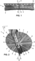
- a device for pre-cutting a column for a floor comprises a pre-cutting means 2 configured to be movable between a rest position and a pre-cutting position.
- the pre-cutting means 2 comprises a membrane 3 capable of being folded back on itself in the rest position and of being deployed in the pre-cutting position.
- membrane 3 has the general shape of a disc.
- the membrane 3 is made from a flexible material, such as plastic or textile, synthetic or natural, possibly recycled.
- the membrane 3 has a diameter slightly smaller than the diameter of the column.
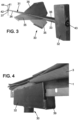
- the pre-cutting means 2 also comprises a rigid structure 4 for deploying the membrane 3 from the folded position to the deployed position.
- the rigid structure 4 is a rigid frame comprising a set of bars 5, for example made of metal.
- Each bar 5 forms a diameter on which the membrane 3 rests securely.
- the pre-cutting means comprises three metal bars delimiting six sectors 6 of the membrane 3, two other sectors 6 being delimited by a corner of the device 1, as will be explained later.
- Each bar 5 is configured to pivot by its middle 7 around a center 8 of the rigid structure 4 corresponding to the center of the deployed membrane 3.
- the pivoting of the bars 5 causes the sectors 6 to unfold or, on the contrary, to fold, like a double fan.
- the rest position of the pre-cutting device 1 coincides with the folded position of the membrane 3, in which the metal bars 5 extend rectilinearly on top of each other.
- the metal bars 5 are at a distance from each other, so that the sectors 6 are taut and the membrane 3 takes the shape of a disc.
- the pre-cutting device 1 comprises a control member 9 for deploying the pre-cutting means 3.
- control member 9 is a rod secured by one of its ends 10 to the center 8 of the membrane 3 and to the middles 7 of the metal bars 5.
- the rod 9 advantageously has a square section.
- the rod 9 extends along an axis X substantially orthogonal to a plane P delimited by the metal bars 5.
- the rod 9 is free to rotate around this axis X relative to the angle iron 12, and is driven in rotation around the axis X by a gripping device manipulated by an operator, as will be detailed below.
- the metal bars 5 being secured by their centers 7 to the rod 9, the rotation of the rod 9 around the axis X controls the rotation of the metal bars 5 around the center 8.
- the pre-cutting device 1 also comprises an element 12 configured to secure the pre-cutting means 2 to a system 30 for positioning the pre-cutting device 1.
- element 12 is a corner.
- the angle iron 12 is a metal profile comprising two wings 13 and 14 arranged orthogonally to each other, so that the profile has an L-shaped section.
- the wing 13 of the angle iron 12 is arranged in the plane P in the deployed position.
- the wing 13 is pierced with a recess 15 crossed by the control rod 9, which allows the control rod 9 to reach the centers 7 of the metal bars 5
- the membrane 3 rests securely on the wing 13 of the angle iron 12.
- the wing 14 is intended to cooperate with a slot in the system 30 for installing the pre-cutting device 1, as will be detailed below.
- the device 1 comprises two membranes whose shape, in the deployed position, is a half-disc, the two membranes then being juxtaposed so as to form a complete disc in the pre-cutting position.
- This variant not shown has a lower manufacturing cost and carbon footprint.
- the rigid structure 4 and/or the angle iron 12 may be made of metal, but also made of a rigid non-metallic material, such as plastic for example.
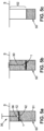
- the system 30 for positioning the pre-cutting device 1 comprises a guide portion 31 for a movement of the pre-cutting device 1 and a holding element 32 for the pre-cutting device 1 during its movement.
- the guide portion 31 comprises a hollow outer tube 33 which allows the system 30 to be guided in the filling material of the column, as will be explained later.
- the hollow outer tube 33 comprises an outer wall 34 provided with three centering devices 35 arranged substantially at 120° two by two.
- the centerers 35 allow guidance of the system 30 in the column, as will be explained below.
- the hollow outer tube 33 is secured by one 36 of its ends 36, 37 to the holding element 32.
- the outer tube 33 comprises on the wall 34 a receiving cell for a distance measuring device, preferably of the laser type, not illustrated, and the position of which can be adjusted along the outer tube.
- the holding element 32 is a parallelepiped 40 provided with a slot 39, and secured by one of its sides to the end 36 of the outer tube 33.
- the slot 39 is configured to cooperate with the angle iron 12 of the pre-cutting device 1.
- the slot 39 has a depth greater than a width of the wing 14 of the angle iron 12 and a spacing greater than a thickness of the wing 14 of the angle iron 12.
- the pre-cutting device 1 is held in the rest position by the system 30, the wing 14 being inserted into the slot 39, the wing 13, the rigid structure 4 and the membrane 3, in the folded position, overhanging the slot 39.
- the holding element 32 holds the pre-cutting device 1 in all directions except one direction allowing the pre-cutting device 1 to be released.
- the angle iron 12 is held simply by friction, as will be explained further below.
- the installation system 30 also includes an inner tube 41 concentric with the outer tube 33.
- the inner tube 41 forms a means of driving the organ of device control.
- the inner tube 41 extends into the outer tube 33 while being held by a stop (not shown) which limits any rotation of the inner tube 41 relative to the outer tube 33 to 180°.
- the inner tube 41 comprises two ends 42, 43, arranged respectively opposite the end 37, 36 of the outer tube 33.
- the end 42 intended to remain above the ground surface, is equipped with a gripping device 44, such as a crank.
- the crank makes it possible to impart a rotational movement to the inner tube 41 and thereby a rotational movement to the control rod 9 relative to the outer tube 33 and consequently to the holding element 32 and to the angle iron 12.
- the end 43 is a housing, a section of which is of the same shape as the section of the rod 9, advantageously square in shape, so that the end 43 receives the control rod 9 of the pre-cutting device.
- the weight of the system 30 can advantageously be adapted to the desired level of leveling, and in particular made heavier for a descent of the pre-cutting device 1 to high depths.
- the outer tube prefferably be grooved so as to form a rack, which makes it possible to control the descent of the system 30 even at great depths.
- the rack is activated manually or by means of an electric or hydraulic motor, preferably mounted on a ball joint to adjust the verticality.
- the entire system for setting up the device 1 and the rack is mounted on a chassis, and installed for example on mobile equipment such as a mini excavator or forklift.
- the holding element with a locking mechanism, provided for example with a trigger, and configured to hold the angle iron 12 in the slot 39 in the rest position and to release the membrane once the device 1 is in place at the desired depth.
- a locking mechanism provided for example with a trigger
- the invention also relates to a method of cutting back a column for a floor.
- the column 50 comprises a recess 51 made for example by drilling or pushing into a ground S and filled with a filling material, such as concrete or mortar, possibly reinforced by a metal frame immersed in the recess 51.
- a filling material such as concrete or mortar
- the invention can be applied in particular to a rigid inclusion type column which allows the reinforcement of the soil S, or to a load transmission column, possibly reinforced.
- the cutting method comprises a step of moving the pre-cutting device 1 in the column 50 in which the filling material is at least partly in pasty form, the pre-cutting device being held in the rest position.
- pasty form it is meant that the filling material, such as concrete or mortar, has not yet acquired its final hardness, so that device 1 and system 3 can be moved into the filling material.
- the pre-cutting device 1 is moved by inserting the positioning system 30 into the column 50, the pre-cutting device 1 being held by the angle iron 12 in the slot 39.
- the installation system 30 is immersed, preferably vertically, in column 50.
- the centerers 35 ensure that the positioning system 30 runs vertically in the column 50.
- the friction exerted on the pre-cutting device 1 is sufficient to hold the wing 34 of the angle iron 12 in the slot 39.
- the method comprises, illustrated in Figure 5b , a step of placing the pre-cutting device 1 in the pre-cutting position at a given depth of the column 50.
- the depth reached is indicated by the distance measuring device, in a manner known to those skilled in the art.
- the position of the pre-cutting device 1 at the desired depth in the column is checked using the laser level and the sight located on the outer tube.
- This depth corresponds to a desired level of leveling, as will be explained.
- the method comprises a subsequent step of raising the positioning system 30, while the pre-cutting device 1 remains stationary due to the pressure exerted by the filling material on the deployed membrane 3.
- the steps for setting up another pre-cutting device are reproduced for another column.
- the process also includes, once the filling material has solidified, a step of cutting off a portion of the column 50 extending to the pre-cutting device 1.
- an operator manipulates a shovel, for example, to top the portion 52 of the column 50 which is flush with the ground surface, up to the pre-cutting device 1, otherwise called the column head.
- the membrane 3 in the deployed position ensures the pre-cutting of the column during the hardening of the filling material in the column 50.
- the shovel applies an impact to the head of the column, which has the effect of breaking the head 52 of the column clearly at the level of the pre-cutting device 1.
- portion 52 ensures that the level is reached.
- the present invention has multiple advantages.
- the level of the level marked by the device 1 and obtained by the cutting back method according to the present invention is precise and is in line in particular with the execution tolerances imposed by the ASIRI recommendations.
- the precision obtained is of the order of a centimeter.
- the overall cost of the work is reduced due to the precision of the indication of the level of the level, which avoids any reworking of the leveling after the work.
- the material resources simply require a single-use device 1, simple to manufacture and position in the column, and a mobile system 30, immediately reusable for each column on the site, possibly removable to allow easy rinsing.
- one of the major interests of the pre-cutting device 1 is to allow the creation of precise leveling courses at depths greater than 1 meter, or even 1.5 meters, which would be impossible to achieve for rigid inclusion type columns with the known state of the art, as already explained.
Landscapes
- Engineering & Computer Science (AREA)
- Life Sciences & Earth Sciences (AREA)
- General Life Sciences & Earth Sciences (AREA)
- Mining & Mineral Resources (AREA)
- Paleontology (AREA)
- Civil Engineering (AREA)
- General Engineering & Computer Science (AREA)
- Structural Engineering (AREA)
- Treatment Of Fiber Materials (AREA)
- Conveying And Assembling Of Building Elements In Situ (AREA)
Claims (8)
- Vorrichtung zum Vorschneiden einer Säule für einen Boden, umfassend ein Vorschneidemittel (2), das dazu konfiguriert ist, um eine im Wesentlichen orthogonal zum Vorschneidemittel verlaufende Achse zwischen einer Ruheposition und einer Vorschneideposition drehbeweglich zu sein, wobei das Vorschneidemittel (2) eine Membran (3) umfasst, die dazu ausgelegt ist, in der Ruheposition gefaltet zu werden und in der Vorschneideposition entfaltet zu werden, wobei die Vorrichtung ferner ein Bedienelement (9) zum Entfalten des Vorschneidemittels und ein Element (12) umfasst, das dazu konfiguriert ist, das Vorschneidemittel (2) an einem Vorschneidevorrichtungs-Positionierungssystem (30) zu befestigen, wobei das Vorschneidevorrichtungs-Positionierungssystem (30) einen Führungsabschnitt (33) für eine Verschiebung der Vorschneidevorrichtung (2) und ein Halteelement (32) für die Vorschneidevorrichtung während der Verschiebung umfasst, wobei das Halteelement (32) einen Schlitz (39) umfasst, der dazu konfiguriert ist, mit dem Element zum Befestigen (12) des Vorschneidemittels (2) am Positionierungssystem (30) der Vorschneidevorrichtung (1) zusammenzuwirken.
- Vorschneidevorrichtung nach Anspruch 1, wobei die Membran (3) in der entfalteten Position eine allgemeine Form einer Scheibe oder einer Halbscheibe aufweist.
- Vorschneidevorrichtung nach einem der Ansprüche 1 oder 2, die eine starre Struktur (4) zum Entfalten der Membran (3) aus der gefalteten Position in die entfaltete Position umfasst.
- System zum Positionieren einer Vorschneidevorrichtung nach einem der Ansprüche 1 bis 3, das einen Führungsabschnitt (33) für eine Verschiebung der Vorschneidevorrichtung (2) und ein Halteelement (32) für die Vorschneidevorrichtung während der Verschiebung umfasst, und wobei das Halteelement (32) einen Schlitz (39) umfasst, der dazu konfiguriert ist, mit dem Element zum Befestigen (12) des Vorschneidemittels (2) am Positionierungssystem (30) der Vorschneidevorrichtung (1) zusammenzuwirken.
- System nach Anspruch 4, das ein Mittel (44) zum Antreiben des Bedienelements der Vorschneidevorrichtung nach einem der Ansprüche 1 bis 3 umfasst.
- System nach einem der Ansprüche 4 oder 5, das einen Stützrahmen des Führungsabschnitts (33) umfasst.
- Verfahren zum Zurückschneiden einer Säule für einen Boden, das Folgendes umfasst:- einen Schritt des Verschiebens der Vorschneidevorrichtung nach einem der Ansprüche 1 bis 3 in der Säule, wobei ein Material, das die Säule mindestens teilweise füllen soll, das sogenannte Füllmaterial, mindestens teilweise in pastöser Form vorliegt, wobei die Vorschneidevorrichtung in der Ruheposition gehalten wird;- einen Schritt des Positionierens der Vorschneidevorrichtung in der Vorschneideposition in einer vorgegebenen Tiefe der Säule durch Drehung des Vorschneidemittels aus der Ruheposition in die Vorschneideposition; und- sobald das Füllmaterial verfestigt ist, einen Schritt des Zurückschneidens eines Abschnitts der Säule, der sich bis zur Vorschneidevorrichtung erstreckt.
- Zurückschneideverfahren nach Anspruch 7, wobei während des Schritts des Verschiebens der Vorschneidevorrichtung die Vorschneidevorrichtung in der Säule durch ein Positionierungssystem nach einem der Ansprüche 4 bis 6 geführt wird.
Applications Claiming Priority (2)
| Application Number | Priority Date | Filing Date | Title |
|---|---|---|---|
| FR1551194A FR3032730B1 (fr) | 2015-02-13 | 2015-02-13 | Dispositif de pre-decoupe d'une colonne pour un sol |
| PCT/FR2016/050294 WO2016128675A1 (fr) | 2015-02-13 | 2016-02-09 | Dispositif de pré-découpe d'une colonne pour un sol |
Publications (2)
| Publication Number | Publication Date |
|---|---|
| EP3256647A1 EP3256647A1 (de) | 2017-12-20 |
| EP3256647B1 true EP3256647B1 (de) | 2025-02-26 |
Family
ID=53200111
Family Applications (1)
| Application Number | Title | Priority Date | Filing Date |
|---|---|---|---|
| EP16707187.7A Active EP3256647B1 (de) | 2015-02-13 | 2016-02-09 | Vorrichtung zum vorschneiden einer säule für einen boden |
Country Status (6)
| Country | Link |
|---|---|
| US (1) | US20180010315A1 (de) |
| EP (1) | EP3256647B1 (de) |
| AU (1) | AU2016217693B2 (de) |
| CA (1) | CA2975344C (de) |
| FR (1) | FR3032730B1 (de) |
| WO (1) | WO2016128675A1 (de) |
Families Citing this family (2)
| Publication number | Priority date | Publication date | Assignee | Title |
|---|---|---|---|---|
| FR3086956B1 (fr) | 2018-10-09 | 2022-06-10 | Soletanche Freyssinet | Dispositif d'arasement d'une colonne |
| US11865738B2 (en) | 2019-10-04 | 2024-01-09 | Keller North America, Inc. | Method and apparatus for creating a preferential breakage plane within cured columns |
Citations (3)
| Publication number | Priority date | Publication date | Assignee | Title |
|---|---|---|---|---|
| DE102006022267A1 (de) * | 2006-05-11 | 2007-11-15 | Sf-Kooperation Gmbh Beton-Konzepte | Verfahren zur Herstellung eines Betonprodukts |
| FR2959957A1 (fr) * | 2010-05-11 | 2011-11-18 | Concept En Chaudronnerie Ind Cci | Procede automatique de decoupe de poutrelles en beton precontraintes et machine pour sa mise en oeuvre |
| US20140091090A1 (en) * | 2010-11-11 | 2014-04-03 | Leifheit Ag | Vessel cover |
Family Cites Families (3)
| Publication number | Priority date | Publication date | Assignee | Title |
|---|---|---|---|---|
| DE3343961A1 (de) * | 1983-12-06 | 1985-06-20 | Gkn Keller Gmbh, 6050 Offenbach | Verfahren zum herstellen von pfaehlen oder pfahlartigen koerpern |
| JPS61169522A (ja) * | 1985-01-21 | 1986-07-31 | Toshihiko Fujii | 地盤改良ソイルセメント杭の杭頭金具 |
| CN104234038A (zh) * | 2014-03-03 | 2014-12-24 | 王磊 | 一种灌注桩免破碎桩头施工工艺 |
-
2015
- 2015-02-13 FR FR1551194A patent/FR3032730B1/fr active Active
-
2016
- 2016-02-09 WO PCT/FR2016/050294 patent/WO2016128675A1/fr not_active Ceased
- 2016-02-09 EP EP16707187.7A patent/EP3256647B1/de active Active
- 2016-02-09 US US15/545,926 patent/US20180010315A1/en not_active Abandoned
- 2016-02-09 CA CA2975344A patent/CA2975344C/fr active Active
- 2016-02-09 AU AU2016217693A patent/AU2016217693B2/en active Active
Patent Citations (3)
| Publication number | Priority date | Publication date | Assignee | Title |
|---|---|---|---|---|
| DE102006022267A1 (de) * | 2006-05-11 | 2007-11-15 | Sf-Kooperation Gmbh Beton-Konzepte | Verfahren zur Herstellung eines Betonprodukts |
| FR2959957A1 (fr) * | 2010-05-11 | 2011-11-18 | Concept En Chaudronnerie Ind Cci | Procede automatique de decoupe de poutrelles en beton precontraintes et machine pour sa mise en oeuvre |
| US20140091090A1 (en) * | 2010-11-11 | 2014-04-03 | Leifheit Ag | Vessel cover |
Also Published As
| Publication number | Publication date |
|---|---|
| FR3032730A1 (fr) | 2016-08-19 |
| CA2975344A1 (fr) | 2016-08-18 |
| AU2016217693A1 (en) | 2017-08-10 |
| WO2016128675A1 (fr) | 2016-08-18 |
| CA2975344C (fr) | 2023-08-15 |
| FR3032730B1 (fr) | 2018-11-02 |
| EP3256647A1 (de) | 2017-12-20 |
| US20180010315A1 (en) | 2018-01-11 |
| AU2016217693B2 (en) | 2019-04-11 |
Similar Documents
| Publication | Publication Date | Title |
|---|---|---|
| EP0574326B1 (de) | Einrichtung, System und Verfahren zum Bohren und Ausrüsten eines seitlichen Bohrloches | |
| EP1525371B1 (de) | Teleskopführungsleitung für offshore-bohren | |
| EP2002061B1 (de) | Bohrwerkzeug | |
| EP3645823B1 (de) | Vertikales bohrsystem vom schneckentyp mit trajektoriekorrekturvorrichtung | |
| JPH1096247A (ja) | 地面に鉛直方向の溝を掘るための伸縮フレーム装置 | |
| EP2652205B1 (de) | Bohrverfahren | |
| JP2017078290A (ja) | 場所打ち杭の構築方法 | |
| CA2975344C (fr) | Dispositif de pre-decoupe d'une colonne pour un sol | |
| WO2015019017A2 (fr) | Dispositif d'etancheite et structure pour element en beton arme comprenant ledit dispositif | |
| EP2204500B1 (de) | Aushubmaschine mit schwenkbarem Kellygestänge | |
| EP3234263B1 (de) | Verfahren zur montage einer unterwasserinstallation mit mindestens einem rohrabschnitt und zugehörige installation | |
| US9677340B1 (en) | High speed precision guide device for creating holes for piles or other support members | |
| JP5745663B1 (ja) | 斜杭引抜補助装置 | |
| FR2534292A1 (fr) | Procede de mise en place de buses de fondation dans un terrain de mauvaise qualite | |
| EP0353152B1 (de) | Vorrichtung zum Abführen von Erdreich für die Herstellung von Tiefgräben | |
| FR2675526A1 (fr) | Procede de guidage de l'outil d'excavation utilise pour la realisation d'une paroi moulee dans le sol, et outil d'excavation pour la mise en óoeuvre de ce procede. | |
| JP2780958B2 (ja) | 水中ケーソン掘削工法及びその掘削装置 | |
| OA10841A (fr) | Dispositif de reconnaissance du sous-sol | |
| JP6219666B2 (ja) | ニューマチックケーソンの沈設方法 | |
| WO2014006204A2 (fr) | Dispositif et procede de forage | |
| EP0533559A1 (de) | Schalengreiferbagger | |
| JP6942911B2 (ja) | 地中杭引き抜き用杭保持体および該保持体を用いた地中杭引き抜き工法 | |
| FR3035916A1 (fr) | Couronne, outil, systeme et procede de forage par carottage | |
| JPH083460Y2 (ja) | 土留壁 | |
| WO2007006905A2 (fr) | Installation et procédé de découpage de structures sous-marines enfoncées dans le fond de la mer |
Legal Events
| Date | Code | Title | Description |
|---|---|---|---|
| STAA | Information on the status of an ep patent application or granted ep patent |
Free format text: STATUS: THE INTERNATIONAL PUBLICATION HAS BEEN MADE |
|
| PUAI | Public reference made under article 153(3) epc to a published international application that has entered the european phase |
Free format text: ORIGINAL CODE: 0009012 |
|
| STAA | Information on the status of an ep patent application or granted ep patent |
Free format text: STATUS: REQUEST FOR EXAMINATION WAS MADE |
|
| 17P | Request for examination filed |
Effective date: 20170719 |
|
| AK | Designated contracting states |
Kind code of ref document: A1 Designated state(s): AL AT BE BG CH CY CZ DE DK EE ES FI FR GB GR HR HU IE IS IT LI LT LU LV MC MK MT NL NO PL PT RO RS SE SI SK SM TR |
|
| AX | Request for extension of the european patent |
Extension state: BA ME |
|
| DAV | Request for validation of the european patent (deleted) | ||
| DAX | Request for extension of the european patent (deleted) | ||
| STAA | Information on the status of an ep patent application or granted ep patent |
Free format text: STATUS: EXAMINATION IS IN PROGRESS |
|
| 17Q | First examination report despatched |
Effective date: 20190503 |
|
| P01 | Opt-out of the competence of the unified patent court (upc) registered |
Effective date: 20230526 |
|
| GRAP | Despatch of communication of intention to grant a patent |
Free format text: ORIGINAL CODE: EPIDOSNIGR1 |
|
| STAA | Information on the status of an ep patent application or granted ep patent |
Free format text: STATUS: GRANT OF PATENT IS INTENDED |
|
| RIC1 | Information provided on ipc code assigned before grant |
Ipc: E02D 9/00 20060101AFI20240704BHEP |
|
| INTG | Intention to grant announced |
Effective date: 20240805 |
|
| GRAJ | Information related to disapproval of communication of intention to grant by the applicant or resumption of examination proceedings by the epo deleted |
Free format text: ORIGINAL CODE: EPIDOSDIGR1 |
|
| STAA | Information on the status of an ep patent application or granted ep patent |
Free format text: STATUS: EXAMINATION IS IN PROGRESS |
|
| GRAP | Despatch of communication of intention to grant a patent |
Free format text: ORIGINAL CODE: EPIDOSNIGR1 |
|
| STAA | Information on the status of an ep patent application or granted ep patent |
Free format text: STATUS: GRANT OF PATENT IS INTENDED |
|
| INTC | Intention to grant announced (deleted) | ||
| INTG | Intention to grant announced |
Effective date: 20241031 |
|
| GRAS | Grant fee paid |
Free format text: ORIGINAL CODE: EPIDOSNIGR3 |
|
| GRAA | (expected) grant |
Free format text: ORIGINAL CODE: 0009210 |
|
| STAA | Information on the status of an ep patent application or granted ep patent |
Free format text: STATUS: THE PATENT HAS BEEN GRANTED |
|
| AK | Designated contracting states |
Kind code of ref document: B1 Designated state(s): AL AT BE BG CH CY CZ DE DK EE ES FI FR GB GR HR HU IE IS IT LI LT LU LV MC MK MT NL NO PL PT RO RS SE SI SK SM TR |
|
| REG | Reference to a national code |
Ref country code: GB Ref legal event code: FG4D Free format text: NOT ENGLISH |
|
| REG | Reference to a national code |
Ref country code: CH Ref legal event code: EP |
|
| REG | Reference to a national code |
Ref country code: DE Ref legal event code: R096 Ref document number: 602016091351 Country of ref document: DE |
|
| REG | Reference to a national code |
Ref country code: IE Ref legal event code: FG4D Free format text: LANGUAGE OF EP DOCUMENT: FRENCH |
|
| REG | Reference to a national code |
Ref country code: NL Ref legal event code: MP Effective date: 20250226 |
|
| PG25 | Lapsed in a contracting state [announced via postgrant information from national office to epo] |
Ref country code: RS Free format text: LAPSE BECAUSE OF FAILURE TO SUBMIT A TRANSLATION OF THE DESCRIPTION OR TO PAY THE FEE WITHIN THE PRESCRIBED TIME-LIMIT Effective date: 20250526 |
|
| PG25 | Lapsed in a contracting state [announced via postgrant information from national office to epo] |
Ref country code: FI Free format text: LAPSE BECAUSE OF FAILURE TO SUBMIT A TRANSLATION OF THE DESCRIPTION OR TO PAY THE FEE WITHIN THE PRESCRIBED TIME-LIMIT Effective date: 20250226 |
|
| PG25 | Lapsed in a contracting state [announced via postgrant information from national office to epo] |
Ref country code: PL Free format text: LAPSE BECAUSE OF FAILURE TO SUBMIT A TRANSLATION OF THE DESCRIPTION OR TO PAY THE FEE WITHIN THE PRESCRIBED TIME-LIMIT Effective date: 20250226 |
|
| PG25 | Lapsed in a contracting state [announced via postgrant information from national office to epo] |
Ref country code: ES Free format text: LAPSE BECAUSE OF FAILURE TO SUBMIT A TRANSLATION OF THE DESCRIPTION OR TO PAY THE FEE WITHIN THE PRESCRIBED TIME-LIMIT Effective date: 20250226 |
|
| REG | Reference to a national code |
Ref country code: LT Ref legal event code: MG9D |
|
| PG25 | Lapsed in a contracting state [announced via postgrant information from national office to epo] |
Ref country code: NO Free format text: LAPSE BECAUSE OF FAILURE TO SUBMIT A TRANSLATION OF THE DESCRIPTION OR TO PAY THE FEE WITHIN THE PRESCRIBED TIME-LIMIT Effective date: 20250526 Ref country code: IS Free format text: LAPSE BECAUSE OF FAILURE TO SUBMIT A TRANSLATION OF THE DESCRIPTION OR TO PAY THE FEE WITHIN THE PRESCRIBED TIME-LIMIT Effective date: 20250626 |
|
| PG25 | Lapsed in a contracting state [announced via postgrant information from national office to epo] |
Ref country code: NL Free format text: LAPSE BECAUSE OF FAILURE TO SUBMIT A TRANSLATION OF THE DESCRIPTION OR TO PAY THE FEE WITHIN THE PRESCRIBED TIME-LIMIT Effective date: 20250226 |
|
| PG25 | Lapsed in a contracting state [announced via postgrant information from national office to epo] |
Ref country code: HR Free format text: LAPSE BECAUSE OF FAILURE TO SUBMIT A TRANSLATION OF THE DESCRIPTION OR TO PAY THE FEE WITHIN THE PRESCRIBED TIME-LIMIT Effective date: 20250226 |
|
| PG25 | Lapsed in a contracting state [announced via postgrant information from national office to epo] |
Ref country code: PT Free format text: LAPSE BECAUSE OF FAILURE TO SUBMIT A TRANSLATION OF THE DESCRIPTION OR TO PAY THE FEE WITHIN THE PRESCRIBED TIME-LIMIT Effective date: 20250626 Ref country code: LV Free format text: LAPSE BECAUSE OF FAILURE TO SUBMIT A TRANSLATION OF THE DESCRIPTION OR TO PAY THE FEE WITHIN THE PRESCRIBED TIME-LIMIT Effective date: 20250226 |
|
| PG25 | Lapsed in a contracting state [announced via postgrant information from national office to epo] |
Ref country code: GR Free format text: LAPSE BECAUSE OF FAILURE TO SUBMIT A TRANSLATION OF THE DESCRIPTION OR TO PAY THE FEE WITHIN THE PRESCRIBED TIME-LIMIT Effective date: 20250527 Ref country code: BG Free format text: LAPSE BECAUSE OF FAILURE TO SUBMIT A TRANSLATION OF THE DESCRIPTION OR TO PAY THE FEE WITHIN THE PRESCRIBED TIME-LIMIT Effective date: 20250226 |
|
| REG | Reference to a national code |
Ref country code: AT Ref legal event code: MK05 Ref document number: 1770719 Country of ref document: AT Kind code of ref document: T Effective date: 20250226 |
|
| PG25 | Lapsed in a contracting state [announced via postgrant information from national office to epo] |
Ref country code: SE Free format text: LAPSE BECAUSE OF FAILURE TO SUBMIT A TRANSLATION OF THE DESCRIPTION OR TO PAY THE FEE WITHIN THE PRESCRIBED TIME-LIMIT Effective date: 20250226 |
|
| PG25 | Lapsed in a contracting state [announced via postgrant information from national office to epo] |
Ref country code: SM Free format text: LAPSE BECAUSE OF FAILURE TO SUBMIT A TRANSLATION OF THE DESCRIPTION OR TO PAY THE FEE WITHIN THE PRESCRIBED TIME-LIMIT Effective date: 20250226 |
|
| PG25 | Lapsed in a contracting state [announced via postgrant information from national office to epo] |
Ref country code: DK Free format text: LAPSE BECAUSE OF FAILURE TO SUBMIT A TRANSLATION OF THE DESCRIPTION OR TO PAY THE FEE WITHIN THE PRESCRIBED TIME-LIMIT Effective date: 20250226 |
|
| PG25 | Lapsed in a contracting state [announced via postgrant information from national office to epo] |
Ref country code: IT Free format text: LAPSE BECAUSE OF FAILURE TO SUBMIT A TRANSLATION OF THE DESCRIPTION OR TO PAY THE FEE WITHIN THE PRESCRIBED TIME-LIMIT Effective date: 20250226 |
|
| PG25 | Lapsed in a contracting state [announced via postgrant information from national office to epo] |
Ref country code: AT Free format text: LAPSE BECAUSE OF FAILURE TO SUBMIT A TRANSLATION OF THE DESCRIPTION OR TO PAY THE FEE WITHIN THE PRESCRIBED TIME-LIMIT Effective date: 20250226 |
|
| PG25 | Lapsed in a contracting state [announced via postgrant information from national office to epo] |
Ref country code: EE Free format text: LAPSE BECAUSE OF FAILURE TO SUBMIT A TRANSLATION OF THE DESCRIPTION OR TO PAY THE FEE WITHIN THE PRESCRIBED TIME-LIMIT Effective date: 20250226 Ref country code: CZ Free format text: LAPSE BECAUSE OF FAILURE TO SUBMIT A TRANSLATION OF THE DESCRIPTION OR TO PAY THE FEE WITHIN THE PRESCRIBED TIME-LIMIT Effective date: 20250226 |
|
| PG25 | Lapsed in a contracting state [announced via postgrant information from national office to epo] |
Ref country code: RO Free format text: LAPSE BECAUSE OF FAILURE TO SUBMIT A TRANSLATION OF THE DESCRIPTION OR TO PAY THE FEE WITHIN THE PRESCRIBED TIME-LIMIT Effective date: 20250226 |
|
| PG25 | Lapsed in a contracting state [announced via postgrant information from national office to epo] |
Ref country code: SK Free format text: LAPSE BECAUSE OF FAILURE TO SUBMIT A TRANSLATION OF THE DESCRIPTION OR TO PAY THE FEE WITHIN THE PRESCRIBED TIME-LIMIT Effective date: 20250226 |
|
| REG | Reference to a national code |
Ref country code: DE Ref legal event code: R097 Ref document number: 602016091351 Country of ref document: DE |
|
| PLBE | No opposition filed within time limit |
Free format text: ORIGINAL CODE: 0009261 |
|
| STAA | Information on the status of an ep patent application or granted ep patent |
Free format text: STATUS: NO OPPOSITION FILED WITHIN TIME LIMIT |
|
| 26N | No opposition filed |
Effective date: 20251127 |
|
| PGFP | Annual fee paid to national office [announced via postgrant information from national office to epo] |
Ref country code: BE Payment date: 20260121 Year of fee payment: 11 |
|
| PGFP | Annual fee paid to national office [announced via postgrant information from national office to epo] |
Ref country code: FR Payment date: 20260121 Year of fee payment: 11 |
|
| PG25 | Lapsed in a contracting state [announced via postgrant information from national office to epo] |
Ref country code: LT Free format text: LAPSE BECAUSE OF FAILURE TO SUBMIT A TRANSLATION OF THE DESCRIPTION OR TO PAY THE FEE WITHIN THE PRESCRIBED TIME-LIMIT Effective date: 20250226 |