EP3256743B1 - Soupape pourvue d'un tiroir de distribution guidé mobile longitudinalement dans un corps de soupape - Google Patents
Soupape pourvue d'un tiroir de distribution guidé mobile longitudinalement dans un corps de soupape Download PDFInfo
- Publication number
- EP3256743B1 EP3256743B1 EP16701252.5A EP16701252A EP3256743B1 EP 3256743 B1 EP3256743 B1 EP 3256743B1 EP 16701252 A EP16701252 A EP 16701252A EP 3256743 B1 EP3256743 B1 EP 3256743B1
- Authority
- EP
- European Patent Office
- Prior art keywords
- valve
- control rod
- control slide
- control
- valve housing
- Prior art date
- Legal status (The legal status is an assumption and is not a legal conclusion. Google has not performed a legal analysis and makes no representation as to the accuracy of the status listed.)
- Active
Links
Images
Classifications
-
- F—MECHANICAL ENGINEERING; LIGHTING; HEATING; WEAPONS; BLASTING
- F16—ENGINEERING ELEMENTS AND UNITS; GENERAL MEASURES FOR PRODUCING AND MAINTAINING EFFECTIVE FUNCTIONING OF MACHINES OR INSTALLATIONS; THERMAL INSULATION IN GENERAL
- F16K—VALVES; TAPS; COCKS; ACTUATING-FLOATS; DEVICES FOR VENTING OR AERATING
- F16K31/00—Actuating devices; Operating means; Releasing devices
- F16K31/02—Actuating devices; Operating means; Releasing devices electric; magnetic
- F16K31/04—Actuating devices; Operating means; Releasing devices electric; magnetic using a motor
- F16K31/05—Actuating devices; Operating means; Releasing devices electric; magnetic using a motor specially adapted for operating hand-operated valves or for combined motor and hand operation
-
- F—MECHANICAL ENGINEERING; LIGHTING; HEATING; WEAPONS; BLASTING
- F15—FLUID-PRESSURE ACTUATORS; HYDRAULICS OR PNEUMATICS IN GENERAL
- F15B—SYSTEMS ACTING BY MEANS OF FLUIDS IN GENERAL; FLUID-PRESSURE ACTUATORS, e.g. SERVOMOTORS; DETAILS OF FLUID-PRESSURE SYSTEMS, NOT OTHERWISE PROVIDED FOR
- F15B13/00—Details of servomotor systems ; Valves for servomotor systems
- F15B13/02—Fluid distribution or supply devices characterised by their adaptation to the control of servomotors
- F15B13/04—Fluid distribution or supply devices characterised by their adaptation to the control of servomotors for use with a single servomotor
- F15B13/044—Fluid distribution or supply devices characterised by their adaptation to the control of servomotors for use with a single servomotor operated by electrically-controlled means, e.g. solenoids, torque-motors
- F15B13/0444—Fluid distribution or supply devices characterised by their adaptation to the control of servomotors for use with a single servomotor operated by electrically-controlled means, e.g. solenoids, torque-motors with rotary electric motor
-
- F—MECHANICAL ENGINEERING; LIGHTING; HEATING; WEAPONS; BLASTING
- F15—FLUID-PRESSURE ACTUATORS; HYDRAULICS OR PNEUMATICS IN GENERAL
- F15B—SYSTEMS ACTING BY MEANS OF FLUIDS IN GENERAL; FLUID-PRESSURE ACTUATORS, e.g. SERVOMOTORS; DETAILS OF FLUID-PRESSURE SYSTEMS, NOT OTHERWISE PROVIDED FOR
- F15B20/00—Safety arrangements for fluid actuator systems; Applications of safety devices in fluid actuator systems; Emergency measures for fluid actuator systems
- F15B20/008—Valve failure
-
- F—MECHANICAL ENGINEERING; LIGHTING; HEATING; WEAPONS; BLASTING
- F16—ENGINEERING ELEMENTS AND UNITS; GENERAL MEASURES FOR PRODUCING AND MAINTAINING EFFECTIVE FUNCTIONING OF MACHINES OR INSTALLATIONS; THERMAL INSULATION IN GENERAL
- F16K—VALVES; TAPS; COCKS; ACTUATING-FLOATS; DEVICES FOR VENTING OR AERATING
- F16K11/00—Multiple-way valves, e.g. mixing valves; Pipe fittings incorporating such valves
- F16K11/02—Multiple-way valves, e.g. mixing valves; Pipe fittings incorporating such valves with all movable sealing faces moving as one unit
- F16K11/06—Multiple-way valves, e.g. mixing valves; Pipe fittings incorporating such valves with all movable sealing faces moving as one unit comprising only sliding valves, i.e. sliding closure elements
- F16K11/065—Multiple-way valves, e.g. mixing valves; Pipe fittings incorporating such valves with all movable sealing faces moving as one unit comprising only sliding valves, i.e. sliding closure elements with linearly sliding closure members
- F16K11/07—Multiple-way valves, e.g. mixing valves; Pipe fittings incorporating such valves with all movable sealing faces moving as one unit comprising only sliding valves, i.e. sliding closure elements with linearly sliding closure members with cylindrical slides
-
- F—MECHANICAL ENGINEERING; LIGHTING; HEATING; WEAPONS; BLASTING
- F16—ENGINEERING ELEMENTS AND UNITS; GENERAL MEASURES FOR PRODUCING AND MAINTAINING EFFECTIVE FUNCTIONING OF MACHINES OR INSTALLATIONS; THERMAL INSULATION IN GENERAL
- F16K—VALVES; TAPS; COCKS; ACTUATING-FLOATS; DEVICES FOR VENTING OR AERATING
- F16K31/00—Actuating devices; Operating means; Releasing devices
- F16K31/02—Actuating devices; Operating means; Releasing devices electric; magnetic
- F16K31/04—Actuating devices; Operating means; Releasing devices electric; magnetic using a motor
-
- F—MECHANICAL ENGINEERING; LIGHTING; HEATING; WEAPONS; BLASTING
- F15—FLUID-PRESSURE ACTUATORS; HYDRAULICS OR PNEUMATICS IN GENERAL
- F15B—SYSTEMS ACTING BY MEANS OF FLUIDS IN GENERAL; FLUID-PRESSURE ACTUATORS, e.g. SERVOMOTORS; DETAILS OF FLUID-PRESSURE SYSTEMS, NOT OTHERWISE PROVIDED FOR
- F15B2211/00—Circuits for servomotor systems
- F15B2211/80—Other types of control related to particular problems or conditions
- F15B2211/895—Manual override
-
- Y—GENERAL TAGGING OF NEW TECHNOLOGICAL DEVELOPMENTS; GENERAL TAGGING OF CROSS-SECTIONAL TECHNOLOGIES SPANNING OVER SEVERAL SECTIONS OF THE IPC; TECHNICAL SUBJECTS COVERED BY FORMER USPC CROSS-REFERENCE ART COLLECTIONS [XRACs] AND DIGESTS
- Y10—TECHNICAL SUBJECTS COVERED BY FORMER USPC
- Y10T—TECHNICAL SUBJECTS COVERED BY FORMER US CLASSIFICATION
- Y10T137/00—Fluid handling
- Y10T137/8593—Systems
- Y10T137/86493—Multi-way valve unit
- Y10T137/86574—Supply and exhaust
- Y10T137/86622—Motor-operated
Definitions
- the invention relates to a valve with a longitudinally movable in a valve housing control spool according to the preamble of claim 1.
- valves for hydraulic applications various types of actuation have been developed over the course of time, ranging from purely manual control with a hand lever via direct electromagnetic control or hydraulic pilot control to highly dynamic servo drives.
- electromechanical control by means of a stepping motor has lately been added as a further valve actuation.
- the U.S. Patent No. 7,591,448 B2 discloses a related solution for a valve. Such solutions are increasingly proven for mobile applications, such as construction machinery, agricultural machinery, forklifts, cranes or other work machines.
- servomotors which indeed generate a rotational movement per se, which, however, can be translated by suitable transmission means in a translational movement.
- linear or stepper motors which generate a translatory movement from the outset.
- the invention has the object to provide a valve of the type mentioned, which avoids the risk of danger in such an accident.
- this object is achieved in a valve of the type mentioned in that the spool for the valve actuation by means of the stepping motor between a rack of the stepping motor and the control rod of the emergency device is movably received in the valve housing that the rack with a with the stepper motor coupled pinion meshing and that the manual operation is preferably made possible via an arranged at the free end of the control rod emergency button.
- the manually operable emergency device is provided, so that an immediate intervention by an operator can be made and therefore must not be resorted to, possibly in turn interference-prone, operating device for possibly required security measures.
- control slide is movably received in the valve housing between a rack of the stepping motor and the control rod of the emergency device, wherein the rack is in meshing engagement with a toothed pinion coupled to the stepping motor.
- the spool is connected at its one free end to a control rod, which led out of the valve housing with its free end actuation by hand, preferably via a arranged at the free end of the control rod emergency button allows.
- a simple and compact emergency device can be realized.
- control rod of the emergency device passes through an energy storage, in particular in the form of a compression spring which is supported with its one free end on a guide of the spool or parts thereof and with its other end to a receiving sleeve, which also from the control rod is penetrated.
- an energy storage in particular in the form of a compression spring which is supported with its one free end on a guide of the spool or parts thereof and with its other end to a receiving sleeve, which also from the control rod is penetrated.
- the arrangement can be made such that the receiving sleeve has at its one free end a cross-sectional reduction, which forms a stop point for the control rod of the emergency device, provided with a cross-sectional widening, is movably guided against the stop point in an end cap of the valve housing.
- the axial length of the receiving sleeve In this case, it can be chosen such that when the stop point is reached by the control rod, the control slide reaches its blocking position, which separates the fluid connection points in the valve housing from one another. It may be a centered zero position of the spool, which corresponds to the safe state.
- the axial length of the receiving sleeve can be further advantageously chosen such that with moving the cross-sectional widening of the control rod away from the stepper motor, the control slide against the action of the energy storage another from the blocking position different operating position in which at least a portion of the fluid connection points is interconnected.
- the control rod to the stepping motor to lift the receiving sleeve against the action of the energy storage from its further stop position on the end cap by means of abutting the cross-section widening, and the spool passes, the movement of the control rod below, in a further operating position , which is different from the blocking position and the one operating position, in which at least a part of the fluid connection points is connected to each other.
- the arrangement can be made with particular advantage so that the spool passes through a guide which, formed in two parts, with a guide part of the end-side longitudinal guide of the spool in this area and with an abutment on the guide member control disc an abutment for forms the support of one end of the energy storage of the emergency device.
- Such a valve can be designed with advantage as a 4/3-way slide valve, for which purpose the valve housing fluid connection points in the form of a Pressure supply connection, two tank connections and two Nutzan say has.
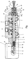
- the invention is illustrated by the example of a 4/3-way spool valve, which, without hydraulic pilot control, according to the state of the art disclosed in said US Pat. No. 7,591,448 B2 by means of a stepping motor 2 as a whole is.
- a longitudinally displaceably guided in the valve housing 6 spool 4 is shown in the figure in its centered, the safe state of a connected system zero position in which all located on the valve housing 6 fluid ports, namely a pressure port P, A and B user connections and tank connections T are separated ,
- the two end portions of the spool 4 are led out via sealing elements 8 from the valve housing 6.
- the slider 4 With its in the figure on the left end portion 10 with the rack 12 of the stepping motor 2 in conjunction, according to the said prior art, the rack 12 translationally moved via a pinion 14.
- the control slide 4 is led out of the valve housing 6 via a guide device formed in two parts.
- This guide device has an actual longitudinal guide for the spool 4 forming guide sleeve 24, which adjoins the sealing element 8 at the outer end of the valve housing 6, and a voltage applied to the outside of the guide sleeve 24 control disk 26.
- the guide sleeve 24 is included in its protruding from the end of the valve housing 6 part of the connecting flange 28 of a bolted to the end of the valve housing 6 housing end cap 30.
- the control disk 26 has a central opening 32 through which a control rod 34 extends, which is bolted to a threaded bore 36 in the spool 4.
- the control rod 34 extends through the interior of a cylindrical spring housing 38 of the end cap 30 and passes with a projecting actuating portion 40 via a located at the end of the end cap 30 sealing member 42 from this.
- an energy storage in the form of a compression spring 44 which is supported at one end to the abutment-forming control disk 26 which abuts the front end of the spool 4.
- the compression spring 44 surrounding the control rod 34 also surrounds the outer side of a receiving sleeve 46, which is penetrated by the control rod 34 and has a radially outwardly projecting edge 48 at its end remote from the control slide 4, which forms the second abutment for the compression spring 44.
- the end edge 48 of the receiving sleeve 46 abuts the end cap 30 at the end of the inner space 38.
- control rod 34 with a cross-sectional widening 50 at the inner edge of the contrast reduced in diameter through hole 51 of the receiving sleeve 46 at. If, during a control movement, the control slide 4 is actuated from the zero position shown in the direction of the stepper motor 2 in order to connect the pressure port P to the useful port A and a tank port T to the useful port B, then the receiving sleeve entrained by the cross-sectional widening 50 of the control rod 34 lifts 46 from the system at the end of the end cap 30 from. The spool 4 thus moves against the action of the compression spring 44 in the figure to the left.
- the control slide 4 is actuated out of the illustrated zero position for a movement directed away from the stepping motor 2, then the cross-sectional widening 50 lifts from the edge of the opening 51 of the receiving sleeve 46 and moves to the right within the receiving sleeve 46 in the figure, this movement being counteracted the action of the compression spring 44 takes place, since the abutment formed by the control disk 26 moves with the control slide 4 to the right.
- the axial length of the receiving sleeve 46 is dimensioned so that the spool 4 is sufficiently far displaced to connect the pressure port P to the user port B and the user port A to a pressure port T.
- control rod 34 is led out with the actuating portion 40 of the end cap 30 and thereby accessible for an emergency operation of the valve.
- an emergency button 52 attached to the end of the actuating portion 40 of the control rod 34 is disposed for direct manual override.
- the construction shown, in which the control rod 34 and the actuating portion 40 are integrally formed, is not mandatory.
- the actuating portion 40 could be a separate adapter member which is bolted to the remainder of the control rod 34.
- the spool 4 itself could be constructively designed so that it protrudes from the spring housing forming end cap 30 and itself is usable as an actuating part for the emergency operation.
Landscapes
- Engineering & Computer Science (AREA)
- General Engineering & Computer Science (AREA)
- Mechanical Engineering (AREA)
- Physics & Mathematics (AREA)
- Fluid Mechanics (AREA)
- Chemical & Material Sciences (AREA)
- Analytical Chemistry (AREA)
- Electrically Driven Valve-Operating Means (AREA)
- Mechanically-Actuated Valves (AREA)
- Multiple-Way Valves (AREA)
Claims (8)
- Soupape comprenant un moteur (2) pas à pas et un tiroir (4) de distribution, qui est guidé de manière à pouvoir se déplacer longitudinalement dans un corps (6) de la soupape et qui, au choix, met en communication fluidiquement ou sépare les uns des autres plusieurs points (P, T, A, B) de raccordement de fluide du corps (6) de la soupape et qui peut être commandée électriquement au moyen du moteur (2) pas à pas, le tiroir (4) de distribution pouvant, en cas de perturbation ou de défaillance, être actionné au moyen d'un dispositif (34, 52) d'urgence et dans lequel le tiroir (4) de distribution est relié à sa une extrémité libre à une barre (34) de commande du dispositif (34, 52) d'urgence qui, sortie du corps (6) de la soupape, rend possible, par son extrémité libre, un actionnement à la main, caractérisée en ce que le tiroir (4) de distribution est, pour l'actionnement de la soupape au moyen du moteur (2) pas à pas, reçu de manière à pouvoir se déplacer dans le corps (6) de la soupape entre une crémaillère (12) du moteur (2) pas à pas et la barre (34) de commande du dispositif d'urgence, en ce que la crémaillère (12) engrène avec un pignon (14) accouplé au moteur (2) pas à pas, et en ce que l'actionnement à la main est rendu possible, de préférence par un bouton (52) en cas d'urgence, disposé à l'extrémité libre de la barre (34) de commande.
- Soupape suivant la revendication 1, caractérisée en ce que la barre (34) de commande du dispositif d'urgence passe à travers un accumulateur d'énergie, notamment sous la forme d'un ressort (44) de compression, qui, par l'une de ses extrémités libres, s'appuie sur un guidage (24, 26) du tiroir (4) de distribution ou de parties (26) de celui-ci et s'appuie, par son autre extrémité, sur un manchon (46) de réception traversé également par la barre (34) de commande.
- Soupape suivant la revendication 2, caractérisée en ce que le manchon (46) de réception a, à l'une de ses extrémités libres, une diminution (51) de la section transversale, qui forme un point de butée pour la barre (34) de commande du dispositif (34, 52) d'urgence, qui, pourvue d'un agrandissement (50) de la section transversale, est guidée en pouvant se déplacer vers le point de butée dans un capot (30) d'extrémité du corps (6) de la soupape.
- Soupape suivant la revendication 3,
caractérisée en ce que la longueur axiale du manchon (46) de réception est choisie de manière à ce que, lorsque le pont de butée est atteint par la barre (34) de commande, le tiroir (4) de distribution arrive dans sa position de blocage séparant les uns des autres les points (PTAB)de raccordement de fluide du corps (6) de la soupape. - Soupape suivant les revendications 3 à 4,
caractérisée en ce que la longueur axiale du manchon (46) de réception est choisie de manière à ce qu'au fur et à mesure que l'agrandissement (50) de la section transversale de la barre (34) de commande s'éloigne du moteur (2) pas à pas, le tiroir (4) de distribution prenne, à l'encontre de l'effet de l'accumulateur (44) d'énergie, une autre position de fonctionnement, différente de la position de blocage, dans laquelle au moins une partie des points (P→B, A→T) de raccordement de fluide communiquent entre eux. - Soupape suivant les revendications 3 à 5,
caractérisée en ce que, lorsque la barre (34) de commande se rapproche du moteur (2) pas à pas au moyen de l'agrandissement (50) de section transversale s'appliquant au point de butée, le manchon (46) de réception quitte, à l'encontre de l'effet de l'accumulateur (44) d'énergie, son autre position de butée sur le capot (36) d'extrémité et le tiroir (4) de distribution, en suivant le déplacement de la barre (34) de commande, arrive dans une autre position de fonctionnement, qui est différente de la position de blocage et de la une position de fonctionnement et dans laquelle au moins une partie des points (P→A, B→T) de raccord de fluide communiquent entre eux. - Soupape suivant les revendications 2 à 6,
caractérisée en ce que le tiroir (4) de distribution pénètre dans un guidage (24, 26), qui, constitué en deux parties, sert, par une partie (24) de guidage, au guidage longitudinal du côté d'extrémité du tiroir (4) de distribution dans cette région et, par un disque (26) de commande s'appuyant sur la partie (24) de guidage, forme une butée pour l'appui de la une extrémité de l'accumulateur (44) d'énergie du dispositif d'urgence. - Soupape suivant l'une des revendications précédentes, caractérisée en ce qu'elle est conçue en vanne à tiroir à 4/3 voies et en ce que, pour cela, le corps (6) de la soupape a des points de raccordement de fluide sous la forme d'un raccord (P) d'alimentation en pression de deux raccords (T) de réservoir et de deux raccords (A, B) utiles.
Applications Claiming Priority (2)
| Application Number | Priority Date | Filing Date | Title |
|---|---|---|---|
| DE102015001883.3A DE102015001883A1 (de) | 2015-02-13 | 2015-02-13 | Ventil mit einem in einem Ventilgehäuse längsverfahrbar geführten Steuerschieber |
| PCT/EP2016/000097 WO2016128106A1 (fr) | 2015-02-13 | 2016-01-20 | Soupape pourvue d'un tiroir de distribution guidé mobile longitudinalement dans un corps de soupape |
Publications (2)
| Publication Number | Publication Date |
|---|---|
| EP3256743A1 EP3256743A1 (fr) | 2017-12-20 |
| EP3256743B1 true EP3256743B1 (fr) | 2019-07-31 |
Family
ID=55221383
Family Applications (1)
| Application Number | Title | Priority Date | Filing Date |
|---|---|---|---|
| EP16701252.5A Active EP3256743B1 (fr) | 2015-02-13 | 2016-01-20 | Soupape pourvue d'un tiroir de distribution guidé mobile longitudinalement dans un corps de soupape |
Country Status (4)
| Country | Link |
|---|---|
| US (1) | US10408363B2 (fr) |
| EP (1) | EP3256743B1 (fr) |
| DE (1) | DE102015001883A1 (fr) |
| WO (1) | WO2016128106A1 (fr) |
Families Citing this family (6)
| Publication number | Priority date | Publication date | Assignee | Title |
|---|---|---|---|---|
| EP3483454A1 (fr) | 2017-11-10 | 2019-05-15 | Société Industrielle de Sonceboz S.A. | Commande hydraulique |
| WO2019220600A1 (fr) * | 2018-05-17 | 2019-11-21 | 川崎重工業株式会社 | Robinet à tiroir |
| CN113324088B (zh) * | 2021-06-16 | 2022-12-13 | 徐州阿马凯液压技术有限公司 | 一种液压阀的液控离合手动控制结构 |
| WO2024254837A1 (fr) | 2023-06-16 | 2024-12-19 | Sharkninja Operating Llc | Buses de mélange de carbonatation |
| DE102024000760A1 (de) * | 2024-03-07 | 2025-09-11 | Hydac Mobilhydraulik Gmbh | Ventil nebst Federungsvorrichtung |
| DE102024000759A1 (de) * | 2024-03-07 | 2025-09-11 | Hydac Mobilhydraulik Gmbh | Ventil |
Family Cites Families (12)
| Publication number | Priority date | Publication date | Assignee | Title |
|---|---|---|---|---|
| GB1590581A (en) * | 1976-10-14 | 1981-06-03 | Hawker Siddeley Dynamics Eng | Electro-hydraulic systems |
| GB2085129B (en) * | 1980-10-09 | 1985-04-03 | Kontak Mfg Co Ltd | Valve actuator |
| US4437388A (en) * | 1981-08-20 | 1984-03-20 | Caterpillar Tractor Company | Dual input pressure compensated fluid control valve |
| DE3704312A1 (de) | 1987-02-12 | 1988-08-25 | Hans Schoen | Elektrohydraulische steueranordnung |
| DE4237852A1 (de) * | 1992-11-10 | 1994-05-11 | Fichtel & Sachs Ag | Hydraulischer Stellzylinder, insbesondere für eine Kraftfahrzeug-Reibungskupplung |
| US7591448B2 (en) | 2006-11-27 | 2009-09-22 | Societe Industrielle De Sonceboz S.A. | Hydraulic control valve system |
| DE102007031429A1 (de) * | 2007-07-05 | 2009-01-08 | Thomas Magnete Gmbh | Antriebsvorrichtung und Betriebsverfahren für einen Steuerschieber eines hydraulischen Ventils |
| US8939173B2 (en) * | 2010-07-14 | 2015-01-27 | Mac Valves, Inc. | Stepper motor operated balanced flow control valve |
| DE102011005868A1 (de) * | 2011-03-21 | 2012-09-27 | Deere & Company | Ventilsteuervorrichtung für ein Fahrzeug |
| DE202011103482U1 (de) * | 2011-04-04 | 2011-11-09 | Ak Regeltechnik Gmbh | Servomodul zur Ventilansteuerung |
| DE102013021317A1 (de) * | 2013-12-16 | 2015-06-18 | Hydac Filtertechnik Gmbh | Hydraulische Ventileinrichtung |
| DK3587830T3 (da) * | 2014-05-01 | 2022-06-13 | Danfoss Power Solutions Ii Technology As | Skydeventilforbindelsesanordning til manuel forbikoblings-indretning |
-
2015
- 2015-02-13 DE DE102015001883.3A patent/DE102015001883A1/de not_active Withdrawn
-
2016
- 2016-01-20 EP EP16701252.5A patent/EP3256743B1/fr active Active
- 2016-01-20 WO PCT/EP2016/000097 patent/WO2016128106A1/fr not_active Ceased
- 2016-01-20 US US15/542,449 patent/US10408363B2/en active Active
Non-Patent Citations (1)
| Title |
|---|
| None * |
Also Published As
| Publication number | Publication date |
|---|---|
| WO2016128106A1 (fr) | 2016-08-18 |
| US20180274691A1 (en) | 2018-09-27 |
| EP3256743A1 (fr) | 2017-12-20 |
| DE102015001883A1 (de) | 2016-09-01 |
| US10408363B2 (en) | 2019-09-10 |
Similar Documents
| Publication | Publication Date | Title |
|---|---|---|
| EP3256743B1 (fr) | Soupape pourvue d'un tiroir de distribution guidé mobile longitudinalement dans un corps de soupape | |
| DE2703349C3 (de) | Ventilvorrichtung zur Steuerung eines Hubkolbens für die Aufwärtsfahrt einer Fahrstuhlkabine | |
| EP3256742B1 (fr) | Soupape de limitation de pression | |
| WO2017108183A1 (fr) | Soupape, en particulier distributeur à tiroir à 4/2 voies | |
| EP0928388A1 (fr) | Mecanisme de commande pour clapet de turbine | |
| EP1985854B1 (fr) | Ensemble pompe | |
| DE102011119784A1 (de) | Fluidbetätigte Greifvorrichtung mit Sicherheitseinrichtung | |
| EP3608286B1 (fr) | Chariot industriel avec système de levage hydraulique et protection électronique du système de levage contre les dysfonctionnements | |
| DE102004044962B4 (de) | Druckmittelbetätigte Stellvorrichtung | |
| DE102013218549A1 (de) | Elektrohydraulischer Aktuator | |
| DE10219718B4 (de) | Hydraulische Ventilanordnung | |
| DE102008061238B4 (de) | Vorrichtung für einen hydraulischen Antrieb für eine elektrische Schaltanlage | |
| DE102013007604A1 (de) | Linearaktuator mit Entriegelungsvorrichtung sowie Fahrwerk für ein Luftfahrzeug | |
| DE102022111767B3 (de) | Schwenkgelenk für einen Roboter | |
| DE2646294C2 (de) | Hydraulische Antriebsvorrichtung für einen Aufzug | |
| DE69411843T2 (de) | Lineares pneumatisches Stellorgan mit einer umorientierbaren Verriegelungseinrichtung | |
| EP1523626B1 (fr) | Cylindre hydraulique | |
| EP2008898B1 (fr) | Composant commandable électrique doté d'un raccordement hydraulique | |
| DE2106195C2 (de) | Verteileranordnung für unter Druck stehendes Strömungsmittel mit zwei Verteilern | |
| DE202008015574U1 (de) | Antriebseinrichtung für ein Pressgerät sowie Pressgerät mit einer solchen Antriebseinrichtung | |
| DE19515884A1 (de) | Einrichtung zur Sicherung einer elektrohydraulischen Antriebseinheit | |
| DE10229276A1 (de) | Vorrichtung zur Überlastsicherung in einer Presse | |
| EP4051911B1 (fr) | Système électrohydraulique d'une soupape | |
| DE102005052692B3 (de) | Elektrohydraulische Überwachungseinrichtung | |
| WO2011116877A1 (fr) | Dispositif de verrouillage d'un composant déplaçable axialement d'une installation hydraulique |
Legal Events
| Date | Code | Title | Description |
|---|---|---|---|
| STAA | Information on the status of an ep patent application or granted ep patent |
Free format text: STATUS: THE INTERNATIONAL PUBLICATION HAS BEEN MADE |
|
| PUAI | Public reference made under article 153(3) epc to a published international application that has entered the european phase |
Free format text: ORIGINAL CODE: 0009012 |
|
| STAA | Information on the status of an ep patent application or granted ep patent |
Free format text: STATUS: REQUEST FOR EXAMINATION WAS MADE |
|
| 17P | Request for examination filed |
Effective date: 20170503 |
|
| AK | Designated contracting states |
Kind code of ref document: A1 Designated state(s): AL AT BE BG CH CY CZ DE DK EE ES FI FR GB GR HR HU IE IS IT LI LT LU LV MC MK MT NL NO PL PT RO RS SE SI SK SM TR |
|
| AX | Request for extension of the european patent |
Extension state: BA ME |
|
| RAP1 | Party data changed (applicant data changed or rights of an application transferred) |
Owner name: HYDAC SYSTEM GMBH |
|
| DAV | Request for validation of the european patent (deleted) | ||
| DAX | Request for extension of the european patent (deleted) | ||
| RAP1 | Party data changed (applicant data changed or rights of an application transferred) |
Owner name: HYDAC SYSTEMS & SERVICES GMBH |
|
| GRAP | Despatch of communication of intention to grant a patent |
Free format text: ORIGINAL CODE: EPIDOSNIGR1 |
|
| STAA | Information on the status of an ep patent application or granted ep patent |
Free format text: STATUS: GRANT OF PATENT IS INTENDED |
|
| INTG | Intention to grant announced |
Effective date: 20190416 |
|
| GRAS | Grant fee paid |
Free format text: ORIGINAL CODE: EPIDOSNIGR3 |
|
| GRAA | (expected) grant |
Free format text: ORIGINAL CODE: 0009210 |
|
| STAA | Information on the status of an ep patent application or granted ep patent |
Free format text: STATUS: THE PATENT HAS BEEN GRANTED |
|
| AK | Designated contracting states |
Kind code of ref document: B1 Designated state(s): AL AT BE BG CH CY CZ DE DK EE ES FI FR GB GR HR HU IE IS IT LI LT LU LV MC MK MT NL NO PL PT RO RS SE SI SK SM TR |
|
| REG | Reference to a national code |
Ref country code: CH Ref legal event code: EP Ref country code: GB Ref legal event code: FG4D Free format text: NOT ENGLISH |
|
| REG | Reference to a national code |
Ref country code: AT Ref legal event code: REF Ref document number: 1161201 Country of ref document: AT Kind code of ref document: T Effective date: 20190815 |
|
| REG | Reference to a national code |
Ref country code: IE Ref legal event code: FG4D Free format text: LANGUAGE OF EP DOCUMENT: GERMAN |
|
| REG | Reference to a national code |
Ref country code: DE Ref legal event code: R096 Ref document number: 502016005792 Country of ref document: DE |
|
| REG | Reference to a national code |
Ref country code: NL Ref legal event code: MP Effective date: 20190731 |
|
| REG | Reference to a national code |
Ref country code: LT Ref legal event code: MG4D |
|
| PG25 | Lapsed in a contracting state [announced via postgrant information from national office to epo] |
Ref country code: HR Free format text: LAPSE BECAUSE OF FAILURE TO SUBMIT A TRANSLATION OF THE DESCRIPTION OR TO PAY THE FEE WITHIN THE PRESCRIBED TIME-LIMIT Effective date: 20190731 Ref country code: BG Free format text: LAPSE BECAUSE OF FAILURE TO SUBMIT A TRANSLATION OF THE DESCRIPTION OR TO PAY THE FEE WITHIN THE PRESCRIBED TIME-LIMIT Effective date: 20191031 Ref country code: NL Free format text: LAPSE BECAUSE OF FAILURE TO SUBMIT A TRANSLATION OF THE DESCRIPTION OR TO PAY THE FEE WITHIN THE PRESCRIBED TIME-LIMIT Effective date: 20190731 Ref country code: LT Free format text: LAPSE BECAUSE OF FAILURE TO SUBMIT A TRANSLATION OF THE DESCRIPTION OR TO PAY THE FEE WITHIN THE PRESCRIBED TIME-LIMIT Effective date: 20190731 Ref country code: PT Free format text: LAPSE BECAUSE OF FAILURE TO SUBMIT A TRANSLATION OF THE DESCRIPTION OR TO PAY THE FEE WITHIN THE PRESCRIBED TIME-LIMIT Effective date: 20191202 Ref country code: SE Free format text: LAPSE BECAUSE OF FAILURE TO SUBMIT A TRANSLATION OF THE DESCRIPTION OR TO PAY THE FEE WITHIN THE PRESCRIBED TIME-LIMIT Effective date: 20190731 Ref country code: FI Free format text: LAPSE BECAUSE OF FAILURE TO SUBMIT A TRANSLATION OF THE DESCRIPTION OR TO PAY THE FEE WITHIN THE PRESCRIBED TIME-LIMIT Effective date: 20190731 Ref country code: NO Free format text: LAPSE BECAUSE OF FAILURE TO SUBMIT A TRANSLATION OF THE DESCRIPTION OR TO PAY THE FEE WITHIN THE PRESCRIBED TIME-LIMIT Effective date: 20191031 |
|
| PG25 | Lapsed in a contracting state [announced via postgrant information from national office to epo] |
Ref country code: RS Free format text: LAPSE BECAUSE OF FAILURE TO SUBMIT A TRANSLATION OF THE DESCRIPTION OR TO PAY THE FEE WITHIN THE PRESCRIBED TIME-LIMIT Effective date: 20190731 Ref country code: ES Free format text: LAPSE BECAUSE OF FAILURE TO SUBMIT A TRANSLATION OF THE DESCRIPTION OR TO PAY THE FEE WITHIN THE PRESCRIBED TIME-LIMIT Effective date: 20190731 Ref country code: GR Free format text: LAPSE BECAUSE OF FAILURE TO SUBMIT A TRANSLATION OF THE DESCRIPTION OR TO PAY THE FEE WITHIN THE PRESCRIBED TIME-LIMIT Effective date: 20191101 Ref country code: LV Free format text: LAPSE BECAUSE OF FAILURE TO SUBMIT A TRANSLATION OF THE DESCRIPTION OR TO PAY THE FEE WITHIN THE PRESCRIBED TIME-LIMIT Effective date: 20190731 Ref country code: IS Free format text: LAPSE BECAUSE OF FAILURE TO SUBMIT A TRANSLATION OF THE DESCRIPTION OR TO PAY THE FEE WITHIN THE PRESCRIBED TIME-LIMIT Effective date: 20191130 Ref country code: AL Free format text: LAPSE BECAUSE OF FAILURE TO SUBMIT A TRANSLATION OF THE DESCRIPTION OR TO PAY THE FEE WITHIN THE PRESCRIBED TIME-LIMIT Effective date: 20190731 |
|
| PG25 | Lapsed in a contracting state [announced via postgrant information from national office to epo] |
Ref country code: TR Free format text: LAPSE BECAUSE OF FAILURE TO SUBMIT A TRANSLATION OF THE DESCRIPTION OR TO PAY THE FEE WITHIN THE PRESCRIBED TIME-LIMIT Effective date: 20190731 |
|
| PG25 | Lapsed in a contracting state [announced via postgrant information from national office to epo] |
Ref country code: DK Free format text: LAPSE BECAUSE OF FAILURE TO SUBMIT A TRANSLATION OF THE DESCRIPTION OR TO PAY THE FEE WITHIN THE PRESCRIBED TIME-LIMIT Effective date: 20190731 Ref country code: PL Free format text: LAPSE BECAUSE OF FAILURE TO SUBMIT A TRANSLATION OF THE DESCRIPTION OR TO PAY THE FEE WITHIN THE PRESCRIBED TIME-LIMIT Effective date: 20190731 Ref country code: EE Free format text: LAPSE BECAUSE OF FAILURE TO SUBMIT A TRANSLATION OF THE DESCRIPTION OR TO PAY THE FEE WITHIN THE PRESCRIBED TIME-LIMIT Effective date: 20190731 Ref country code: RO Free format text: LAPSE BECAUSE OF FAILURE TO SUBMIT A TRANSLATION OF THE DESCRIPTION OR TO PAY THE FEE WITHIN THE PRESCRIBED TIME-LIMIT Effective date: 20190731 |
|
| PG25 | Lapsed in a contracting state [announced via postgrant information from national office to epo] |
Ref country code: SM Free format text: LAPSE BECAUSE OF FAILURE TO SUBMIT A TRANSLATION OF THE DESCRIPTION OR TO PAY THE FEE WITHIN THE PRESCRIBED TIME-LIMIT Effective date: 20190731 Ref country code: SK Free format text: LAPSE BECAUSE OF FAILURE TO SUBMIT A TRANSLATION OF THE DESCRIPTION OR TO PAY THE FEE WITHIN THE PRESCRIBED TIME-LIMIT Effective date: 20190731 Ref country code: IS Free format text: LAPSE BECAUSE OF FAILURE TO SUBMIT A TRANSLATION OF THE DESCRIPTION OR TO PAY THE FEE WITHIN THE PRESCRIBED TIME-LIMIT Effective date: 20200224 Ref country code: CZ Free format text: LAPSE BECAUSE OF FAILURE TO SUBMIT A TRANSLATION OF THE DESCRIPTION OR TO PAY THE FEE WITHIN THE PRESCRIBED TIME-LIMIT Effective date: 20190731 |
|
| REG | Reference to a national code |
Ref country code: DE Ref legal event code: R097 Ref document number: 502016005792 Country of ref document: DE |
|
| PLBE | No opposition filed within time limit |
Free format text: ORIGINAL CODE: 0009261 |
|
| STAA | Information on the status of an ep patent application or granted ep patent |
Free format text: STATUS: NO OPPOSITION FILED WITHIN TIME LIMIT |
|
| PG2D | Information on lapse in contracting state deleted |
Ref country code: IS |
|
| PG25 | Lapsed in a contracting state [announced via postgrant information from national office to epo] |
Ref country code: IS Free format text: LAPSE BECAUSE OF FAILURE TO SUBMIT A TRANSLATION OF THE DESCRIPTION OR TO PAY THE FEE WITHIN THE PRESCRIBED TIME-LIMIT Effective date: 20191030 |
|
| 26N | No opposition filed |
Effective date: 20200603 |
|
| PG25 | Lapsed in a contracting state [announced via postgrant information from national office to epo] |
Ref country code: SI Free format text: LAPSE BECAUSE OF FAILURE TO SUBMIT A TRANSLATION OF THE DESCRIPTION OR TO PAY THE FEE WITHIN THE PRESCRIBED TIME-LIMIT Effective date: 20190731 Ref country code: MC Free format text: LAPSE BECAUSE OF FAILURE TO SUBMIT A TRANSLATION OF THE DESCRIPTION OR TO PAY THE FEE WITHIN THE PRESCRIBED TIME-LIMIT Effective date: 20190731 |
|
| REG | Reference to a national code |
Ref country code: CH Ref legal event code: PL |
|
| GBPC | Gb: european patent ceased through non-payment of renewal fee |
Effective date: 20200120 |
|
| REG | Reference to a national code |
Ref country code: BE Ref legal event code: MM Effective date: 20200131 |
|
| PG25 | Lapsed in a contracting state [announced via postgrant information from national office to epo] |
Ref country code: LU Free format text: LAPSE BECAUSE OF NON-PAYMENT OF DUE FEES Effective date: 20200120 Ref country code: GB Free format text: LAPSE BECAUSE OF NON-PAYMENT OF DUE FEES Effective date: 20200120 Ref country code: FR Free format text: LAPSE BECAUSE OF NON-PAYMENT OF DUE FEES Effective date: 20200131 |
|
| PG25 | Lapsed in a contracting state [announced via postgrant information from national office to epo] |
Ref country code: LI Free format text: LAPSE BECAUSE OF NON-PAYMENT OF DUE FEES Effective date: 20200131 Ref country code: CH Free format text: LAPSE BECAUSE OF NON-PAYMENT OF DUE FEES Effective date: 20200131 Ref country code: BE Free format text: LAPSE BECAUSE OF NON-PAYMENT OF DUE FEES Effective date: 20200131 |
|
| PG25 | Lapsed in a contracting state [announced via postgrant information from national office to epo] |
Ref country code: IE Free format text: LAPSE BECAUSE OF NON-PAYMENT OF DUE FEES Effective date: 20200120 |
|
| REG | Reference to a national code |
Ref country code: AT Ref legal event code: MM01 Ref document number: 1161201 Country of ref document: AT Kind code of ref document: T Effective date: 20210120 |
|
| PG25 | Lapsed in a contracting state [announced via postgrant information from national office to epo] |
Ref country code: AT Free format text: LAPSE BECAUSE OF NON-PAYMENT OF DUE FEES Effective date: 20210120 |
|
| PG25 | Lapsed in a contracting state [announced via postgrant information from national office to epo] |
Ref country code: MT Free format text: LAPSE BECAUSE OF FAILURE TO SUBMIT A TRANSLATION OF THE DESCRIPTION OR TO PAY THE FEE WITHIN THE PRESCRIBED TIME-LIMIT Effective date: 20190731 Ref country code: CY Free format text: LAPSE BECAUSE OF FAILURE TO SUBMIT A TRANSLATION OF THE DESCRIPTION OR TO PAY THE FEE WITHIN THE PRESCRIBED TIME-LIMIT Effective date: 20190731 |
|
| PG25 | Lapsed in a contracting state [announced via postgrant information from national office to epo] |
Ref country code: MK Free format text: LAPSE BECAUSE OF FAILURE TO SUBMIT A TRANSLATION OF THE DESCRIPTION OR TO PAY THE FEE WITHIN THE PRESCRIBED TIME-LIMIT Effective date: 20190731 |
|
| PGFP | Annual fee paid to national office [announced via postgrant information from national office to epo] |
Ref country code: DE Payment date: 20250131 Year of fee payment: 10 |
|
| PGFP | Annual fee paid to national office [announced via postgrant information from national office to epo] |
Ref country code: IT Payment date: 20250113 Year of fee payment: 10 |