EP3256747B1 - Stanzniet und verfahren zur herstellung einer stanznietverbindung - Google Patents
Stanzniet und verfahren zur herstellung einer stanznietverbindung Download PDFInfo
- Publication number
- EP3256747B1 EP3256747B1 EP15794150.1A EP15794150A EP3256747B1 EP 3256747 B1 EP3256747 B1 EP 3256747B1 EP 15794150 A EP15794150 A EP 15794150A EP 3256747 B1 EP3256747 B1 EP 3256747B1
- Authority
- EP
- European Patent Office
- Prior art keywords
- shank
- punch
- smaller
- internal diameter
- diameter
- Prior art date
- Legal status (The legal status is an assumption and is not a legal conclusion. Google has not performed a legal analysis and makes no representation as to the accuracy of the status listed.)
- Active
Links
Images


Classifications
-
- F—MECHANICAL ENGINEERING; LIGHTING; HEATING; WEAPONS; BLASTING
- F16—ENGINEERING ELEMENTS AND UNITS; GENERAL MEASURES FOR PRODUCING AND MAINTAINING EFFECTIVE FUNCTIONING OF MACHINES OR INSTALLATIONS; THERMAL INSULATION IN GENERAL
- F16B—DEVICES FOR FASTENING OR SECURING CONSTRUCTIONAL ELEMENTS OR MACHINE PARTS TOGETHER, e.g. NAILS, BOLTS, CIRCLIPS, CLAMPS, CLIPS OR WEDGES; JOINTS OR JOINTING
- F16B19/00—Bolts without screw-thread; Pins, including deformable elements; Rivets
- F16B19/04—Rivets; Spigots or the like fastened by riveting
- F16B19/08—Hollow rivets; Multi-part rivets
-
- F—MECHANICAL ENGINEERING; LIGHTING; HEATING; WEAPONS; BLASTING
- F16—ENGINEERING ELEMENTS AND UNITS; GENERAL MEASURES FOR PRODUCING AND MAINTAINING EFFECTIVE FUNCTIONING OF MACHINES OR INSTALLATIONS; THERMAL INSULATION IN GENERAL
- F16B—DEVICES FOR FASTENING OR SECURING CONSTRUCTIONAL ELEMENTS OR MACHINE PARTS TOGETHER, e.g. NAILS, BOLTS, CIRCLIPS, CLAMPS, CLIPS OR WEDGES; JOINTS OR JOINTING
- F16B19/00—Bolts without screw-thread; Pins, including deformable elements; Rivets
- F16B19/04—Rivets; Spigots or the like fastened by riveting
- F16B19/08—Hollow rivets; Multi-part rivets
- F16B19/086—Self-piercing rivets
-
- B—PERFORMING OPERATIONS; TRANSPORTING
- B21—MECHANICAL METAL-WORKING WITHOUT ESSENTIALLY REMOVING MATERIAL; PUNCHING METAL
- B21J—FORGING; HAMMERING; PRESSING METAL; RIVETING; FORGE FURNACES
- B21J15/00—Riveting
-
- B—PERFORMING OPERATIONS; TRANSPORTING
- B21—MECHANICAL METAL-WORKING WITHOUT ESSENTIALLY REMOVING MATERIAL; PUNCHING METAL
- B21J—FORGING; HAMMERING; PRESSING METAL; RIVETING; FORGE FURNACES
- B21J15/00—Riveting
- B21J15/02—Riveting procedures
- B21J15/025—Setting self-piercing rivets
-
- B—PERFORMING OPERATIONS; TRANSPORTING
- B21—MECHANICAL METAL-WORKING WITHOUT ESSENTIALLY REMOVING MATERIAL; PUNCHING METAL
- B21J—FORGING; HAMMERING; PRESSING METAL; RIVETING; FORGE FURNACES
- B21J15/00—Riveting
- B21J15/02—Riveting procedures
- B21J15/04—Riveting hollow rivets mechanically
-
- B—PERFORMING OPERATIONS; TRANSPORTING
- B21—MECHANICAL METAL-WORKING WITHOUT ESSENTIALLY REMOVING MATERIAL; PUNCHING METAL
- B21J—FORGING; HAMMERING; PRESSING METAL; RIVETING; FORGE FURNACES
- B21J15/00—Riveting
- B21J15/10—Riveting machines
- B21J15/36—Rivet sets, i.e. tools for forming heads; Mandrels for expanding parts of hollow rivets
-
- F—MECHANICAL ENGINEERING; LIGHTING; HEATING; WEAPONS; BLASTING
- F16—ENGINEERING ELEMENTS AND UNITS; GENERAL MEASURES FOR PRODUCING AND MAINTAINING EFFECTIVE FUNCTIONING OF MACHINES OR INSTALLATIONS; THERMAL INSULATION IN GENERAL
- F16B—DEVICES FOR FASTENING OR SECURING CONSTRUCTIONAL ELEMENTS OR MACHINE PARTS TOGETHER, e.g. NAILS, BOLTS, CIRCLIPS, CLAMPS, CLIPS OR WEDGES; JOINTS OR JOINTING
- F16B19/00—Bolts without screw-thread; Pins, including deformable elements; Rivets
- F16B19/04—Rivets; Spigots or the like fastened by riveting
-
- F—MECHANICAL ENGINEERING; LIGHTING; HEATING; WEAPONS; BLASTING
- F16—ENGINEERING ELEMENTS AND UNITS; GENERAL MEASURES FOR PRODUCING AND MAINTAINING EFFECTIVE FUNCTIONING OF MACHINES OR INSTALLATIONS; THERMAL INSULATION IN GENERAL
- F16B—DEVICES FOR FASTENING OR SECURING CONSTRUCTIONAL ELEMENTS OR MACHINE PARTS TOGETHER, e.g. NAILS, BOLTS, CIRCLIPS, CLAMPS, CLIPS OR WEDGES; JOINTS OR JOINTING
- F16B19/00—Bolts without screw-thread; Pins, including deformable elements; Rivets
- F16B19/04—Rivets; Spigots or the like fastened by riveting
- F16B19/08—Hollow rivets; Multi-part rivets
- F16B19/10—Hollow rivets; Multi-part rivets fastened by expanding mechanically
Definitions
- the present invention relates to a punch rivet for joining two workpieces, said punch rivet having a head and a shank, wherein the shank is realized as a hollow shank with a shank internal diameter, a shank external diameter and a shank end face, wherein on the shank end face a ring cutting edge is realized, the diameter of which is smaller than the shank external diameter and wherein the shank internal diameter merges into the ring cutting edge by means of a cutting radius.
- a punch rivet of this type is known from document DE 10 2005 052 360 B4 and from document DE 10 2009 039 936 A1 .
- EP 2 080 915 discloses also a similar punch rivet.
- the invention additionally relates to a method for producing a punch-riveted joint between at least two workpieces, one of which consists in particular of a high-strength material with a strength of at least 600 MPa and preferably of a maximum of 1000 MPa and comprises in particular a thickness of at least 0.5 mm.
- the present invention relates to a workpiece arrangement produced from at least two workpieces which are joined by means of at least one punch rivet of this type or by using a punch riveting method of this type.
- Punch riveting is a transformative joining process and can be carried out using so-called solid rivets and so-called semi-hollow rivets.
- the present case is concerned with punch riveting using a semi-hollow rivet which is realized with a hollow shank.
- Said method is characterized in that the semi-hollow rivet is driven into an arrangement of two workpieces (in particular two metal sheets), the uppermost workpiece being pierced (perforated) by the hollow shank.
- a die on which the bottommost workpiece rests, is designed such that the hollow shank is hereafter radially expanded and is driven radially into the bottom workpiece such that an undercut is formed.
- the bottom workpiece is as a rule not severed such that the side of the bottom workpiece facing the die remains closed and as a result is less susceptible to rust.
- Said punch riveting method with a semi-hollow rivet has been used for some years more and more in the automobile industry.
- the punch riveting method is suitable in particular for joining workpieces produced from different materials (for example steel and aluminium). As there is a trend in particular in car body construction toward a combination of different materials adapted to the respective intended purpose, the punch riveting method is a joining method preferred for this case in comparison to welding.
- the material of the bottom workpiece on the die side should have good cold forming properties and should have material characteristics that are as homogeneous as possible.
- the punch rivets used for this purpose have to have a correspondingly high strength (rivet hardness), in particular in order to be able to pierce such a workpiece produced from a high-strength material.
- the punch rivet is to have adequate deformability in its shank region in order to provide a sufficient undercut in the finished punch-riveted joint.
- punch riveting high-strength metal joints are a sufficiently high level of rigidity for penetrating such high-strength metal sheets as well as a sufficiently large shank interior volume in order to receive the punch slugs from the metal sheet layer on the punch side.
- the semi-hollow rivet described there comprises a cylindrical hollow shank, a sharp ring cutting edge being realized on the exterior edge of the end face of the shank.
- the internal diameter merges into the shank external diameter by means of a cutting radius.
- Said C-rivet was originally developed for pure aluminium joints or combinations of low strength steel plates.
- the C-rivet is less suitable for punch riveting high-strength workpieces as the C-rivet has a tendency to expand strongly during the punch riveting operation such that there is only a little material present in the undercut region of the bottom workpiece. The obtainable strength is consequently relatively small.
- a modified C-rivet with a sharp ring cutting edge which is, however, at a spacing from the shank external diameter is known from document DE 203 19 610 U1 .
- a ring cutting edge is realized on the shank end face, the diameter of which is smaller than the shank external diameter.
- the ring cutting edge is realized as a flat ring surface which is aligned in the radial direction and merges into the shank external diameter by means of a shank external bevel and as a result is at a spacing from the shank external diameter.
- the shank internal diameter merges into said ring surface by means of a relatively small radius.
- the P-rivet certainly has better characteristics than the C-rivet when punch riveting high-strength workpieces. Nonetheless, there is still a need for improvement in this regard even with the P-rivet.
- the semi-hollow punch rivet which was made known from document DE 10 2009 039 936 A1 mentioned in the introduction, is generally suitable for joining high-strength sheet layers. Nevertheless, there is generally a need for improvement with regard to the known semi-hollow punch rivets.
- the ratio of shank internal diameter to shank external diameter is smaller than 0.55. In addition, it is preferred when said ratio is greater than 0.52.
- the above object is achieved by a method for producing a punch-riveted joint between at least two workpieces, one of which consists in particular of a high-strength material with a strength of at least 600 MPa and comprises in particular a thickness of at least 0.5 mm, said method having the steps:
- the residual bottom thickness is the axial thickness of the material of the sheet layer on the punch side, at the point where the axial height of said sheet layer is at its smallest, this lying as a rule in the axial projection for instance in the region of the shank end face between shank internal diameter and shank external diameter.
- a smaller expansion is obtained in the case of the punch rivet according to the invention, which is achieved substantially as a result of the radial shank thickness which is greater compared to said prior art.
- Said radial shank thickness is preferably greater than 1.1 mm and preferably greater than 1.2 mm in the case of the punch rivet according to the invention.
- the shank thickness is smaller than 1.7 mm.
- the difference between the shank external diameter and the shank internal diameter is preferably greater than 2.2 mm in the case of the punch rivet according to the invention, in particular greater than 2.4 mm and preferably smaller than 3.0 mm. In a particularly preferred manner, said difference is greater than 2.45 mm and smaller than 2.6 mm.
- the punch rivet according to the invention comprises a ring cutting edge, the diameter of which is smaller than the shank external diameter.
- the method according to the invention can be used for high-strength materials with a strength of at least 600 MPa, consequently with workpieces produced from steel but also with less solid materials such a light metals. It is also possible to join two workpieces produced from aluminium. In a preferred manner, the workpieces have a thickness of between 0.8 mm and 2.5 mm. In the case of particularly high-strength materials with a strength of up to 1000 MPa or even 1500 MPa or more, in a preferred manner the workpieces used are relatively thin, for example 0.8 mm.
- the ring cutting edge merges by means of a profile into the shank internal diameter which includes a cutting radius and as an option a conical surface, wherein the ratio of cutting radius to shank external diameter is smaller than 0.3.
- a less pointed geometry of the shank in the region of the end face can be achieved as a result of said measure. This can contribute to the fact that the punch rivet expands less radially during the punch riveting process, but can nevertheless provide sufficient deformability to realize an undercut.
- the ring cutting edge merges into the shank internal diameter by means of a profile which comprises a cutting radius which adjoins the ring cutting edge and which merges tangentially into the shank internal diameter, wherein a ratio of cutting portion height to shank external diameter is smaller or equal to 0.25.
- said ratio can be smaller than 0.23, preferably smaller than 0.2.
- an opening angle is preferably set up which is greater than 90°, but is preferably smaller than 135°.
- the ring cutting edge merges into the shank internal diameter by means of a profile which comprises a cutting radius which adjoins the ring cutting edge and which merges tangentially into a conical surface which adjoins the shank internal diameter.
- the boundary between the conical surface and the shank internal diameter can be rounded off by a suitable small radius.
- the opening angle adjoining the ring cutting edge can be relatively large, it being possible to set up a geometry of the shank that is not too bulky, however, as a result of the conical surface.
- the conical surface preferably defines an opening angle which is smaller than 50°.
- the opening angle can be in particular smaller than 40°, preferably smaller than 35°.
- the conical angle is preferably greater than 20°.
- the ring cutting edge merges into the shank internal diameter by means of a profile which comprises a cutting radius which adjoins the shank internal diameter and which merges tangentially into a conical surface which adjoins the ring cutting edge.
- the shank in the region of its interior at the transition between the ring cutting edge and the shank internal diameter, the shank initially comprises a conical surface which then merges into the shank internal diameter by means of the cutting radius.
- An opening angle can be precisely defined as a result.
- the conical surface preferably comprises an opening angle which is greater than 55°.
- the opening angle can be greater than 60°, preferably greater than 80°.
- the opening angle of the conical surface is preferably smaller than 90°.
- the ring cutting edge into the shank internal diameter merges by means of a profile which comprises a conical surface which adjoins the ring cutting edge and which adjoins the shank internal diameter.
- the shank external diameter merges by means of an underhead radius and a head cone into the external circumference of the head, wherein the ratio of the underhead radius to the shank external diameter is smaller than 0.13.
- the head cone preferably directly adjoins the external circumference of the head.
- the ring cutting edge merges into the shank external diameter by means of a shank external bevel which is aligned at a bevel angle smaller than 40° with reference to a radial plane and/or which comprises an axial external bevel height which is smaller than or equal to 0.3 mm.
- the expanding of the shank during the punch riveting process can be suitably adjusted as a result.
- the ratio of cutting radius to shank external diameter is smaller than 0.7.
- the shank is prevented from becoming too thin in the region of the end face. Consequently, a high punching effect can be obtained even in the case of high-strength steels.
- the transition radius can be a very small radius of, for example, smaller than 0.2 mm, in particular smaller than 0.15 mm. Stresses in this region during the punching operation are avoided as a result of the transition radius.
- the ratio of a head external diameter to the shank external diameter is smaller than 1.44.
- the punch rivet is provided with a relatively large shank external diameter.
- the ring surface which the shank comprises in the axial projection can be enlarged as a result.
- the stability of the punch rivet during the punching operation can be increased as a result.
- the ring cutting edge comprises a cutting ring surface which is aligned in the radial direction, the radial width of which is chosen such that the ratio of ring surface width to the radial thickness of the shank is within the range of between 0.02 and 0.08.
- the ring surface width is consequently generally smaller compared to the P-rivet such that a collapsing or compressing of the shank during a punching operation is better able to be prevented.
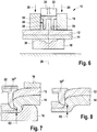
- a punch riveting device is given the general reference of 10 in Figure 6 .
- the punch riveting device 10 serves for the purpose of joining a first workpiece 12 and a second workpiece 14 together.
- the workpieces 12, 14 can be in particular sheets, such as are used in vehicle body construction.
- the thickness of the workpieces 12, 14 can be within the range of between, for example, 0.5 mm and 4 mm, in particular within the range of between 1 mm and 2. 5 mm.
- the materials of the workpieces 12, 14 must meet the usual requirements for materials that can be cold formed. These materials are frequently alloyed metals such as steel, aluminium and magnesium. However, it is also possible to produce one of the workpieces 12, 14, in particular the upper workpiece, from a plastics material.
- the punch riveting device 10 comprises a die 16, onto which the workpieces 12, 14 are placed directly one on top of the other. Hold-down clamps which are pressed onto the workpiece arrangement at a certain hold-down force 20 serve for fixing the workpieces.
- the punch 22 serves for the purpose of driving a punch rivet 30 into the workpiece arrangement 12, 14.
- the punch rivet 30 is realized as a semi-hollow punch rivet, with a head 32 and a hollow shank 34 which extends from said head in the axial direction and on the end face of which a cutting edge 36 is realized.
- the shank 34 When the punch 22 moves down, the shank 34 initially pierces the upper workpiece 14 on the punch side such that a so-called punch slug is cut out from said upper workpiece. As the punching operation progresses, the free shank end 34 is driven into the workpiece 14 on the die side. A cavity 38, which in a manner known per se enables the shank 34 to expand radially as the punch riveting operation progresses such that the free end of the shank 34, when viewed in the axial direction, penetrates behind material of the workpiece 14 on the die side, is realized in the die 16. As a rule, the punch rivet 30 is driven into the workpiece arrangement 12, 14 by such an amount until the head closes off in a flush manner with the surface of the workpiece 12 on the punch side.
- punch rivets 30 are available as a rule for the joining of workpieces produced from the most varied materials.
- Figures 1 and 2 show an embodiment of a punch rivet 30 which is suitable, in particular, in conjunction with workpieces 12, 14 produced from high-strength materials.
- the workpiece 14 on the die side can comprise a strength, for example, of greater than 400 MPa, preferably however of not more than 1200 MPa.
- the workpiece on the punch side can comprise high-strength materials with strengths of up to 1000 MPa or more than 1000 MPa or more than 1200 MPa.
- the punch rivet 30 itself is also produced from a high-strength material, for example with a rivet hardness of greater than 1500 MPa, in particular greater than 1700 MPa.
- the punch rivet 30 is realized so as to be rotationally symmetrical about the longitudinal axis 26 and comprises a head 32 and a shank 34.
- the shank 34 is divided into a shank portion 40 which connects to the head 32 and a cutting portion 42.
- the shank portion 40 is realized in a hollow cylindrical manner and comprises a shank external diameter D1 and a shank internal diameter D3.
- the cutting portion 42 comprises a cutting portion height M2.
- the head 32 comprises a flat head top surface 44 and a cylindrical head external surface 46.
- the head top surface 44 comprises a head external diameter D2.
- the head external surface 46 comprises a head external surface height M1.
- the head 32 Inside the shank 34, the head 32 comprises a head bottom surface 48 which, in the present case, is realized obtusely tapered or roundedly reduced and merges into the shank internal diameter D3 by means of a head internal radius R3.
- the shank external diameter D1 merges into the bottom surface of the head external surface 46 by means of an underhead radius R1.
- the underhead radius R1 is arranged such that it merges tangentially into both the shank external diameter D1 and into a conical surface 49 which is arranged at a head cone angle ⁇ 0 with respect to the head top surface 44.
- the head 32 comprises a head height H which extends from the head top surface 44 to the head bottom surface 48.
- the shank 30 comprises in the region of the shank portion 40 a shank thickness M5 which is equal to half of the difference between the shank external diameter D1 and the shank internal diameter D3.
- the shank 34 additionally comprises a ring surface which is defined on the external circumference by the shank external diameter D1 and on the inside circumference by the shank internal diameter D3.
- a ring cutting edge 50 which is realized as a planar cutting ring surface and extends in the radial direction (see Figure 2 ), is realized on the end face of the shank 32, more precisely of the cutting portion 42.
- the internal diameter of the cutting ring surface is shown at D4.
- the cutting ring surface comprises a radial width M3.
- the ring cutting edge 50 consequently lies somewhat outside the middle shank diameter which is formed by the average between the shank external diameter D1 and the shank internal diameter D3.
- the external circumference of the cutting ring surface merges into the shank external diameter D1 by means of a shank external bevel 52.
- the shank external bevel 52 assumes an angle ⁇ 1 with a radial plane.
- the shank external bevel 52 merges into the shank external diameter D1 by means of a transition radius which is not designated in any more detail.
- the external bevel height is shown in Figure 2 at M4.
- the internal circumference of the cutting ring surface merges into the shank internal diameter D3 by means of a cutting radius R2.
- the cutting radius R2 merges tangentially into the shank internal diameter D3 and ends by realizing an opening angle in the cutting ring surface.
- the radius R2 extends more precisely from the shank internal diameter D3 toward the cutting ring surface in such a manner that the inside surface of the shank produces an opening angle ⁇ 2 of approximately 100°.
- the opening angle ⁇ 2 in the case of said embodiment, should be greater than 80° and is preferably smaller than 135°.
- the above-mentioned dimensions of the punch rivet 30 are provided in the following table 1.
- preferred value ranges are given for the respective values and in addition an example of a particularly preferred embodiment, as is shown in Figure 2 .
- the table 1 gives preferred ratios of said dimensions from which it can be seen how a punch rivet according to the invention can be dimensioned for application examples.
- the punch rivet 30 can be realized in different lengths, in this connection in each case the length of the shank portion 40 varying.
- the cutting portion 42 preferably remains unchanged with all the embodiments with different lengths.
- Figure 1 shows the axial overall length of the punch rivet 30 at M6.
- the punch rivet 30 can be realized with a relatively large shank external diameter, as a result of which the stability is increased during the punch riveting operation.
- the shank 34 can be realized with a relative large ring surface in the axial projection.
- the result of the ratio of M2/D1 > 0.25 can be that a relatively large volume can be received in the interior of the shank during the punching operation. Accordingly, it is possible for the shank to receive at least extensively a punch slug severed out of the workpiece on the die side. This prevents the punch slug being pressed down axially by the shank, which would result either in the punch rivet being compressed or in a fracture in the workpiece on the side of the die.
- FIGS 3 and 5 show further embodiments of punch rivets which correspond in general to the punch rivet 30 of Figures 1 and 2 as regards design and method of operation. Identical elements are consequently characterized by identical references. Essentially the differences are explained below.
- the ring cutting edge merges into the shank internal diameter by means of a profile which comprises a cutting radius R" which adjoins the ring cutting edge and which merges tangentially into a conical surface 60 which adjoins the shank internal diameter.
- the conical surface 60 comprises in this case an opening angle ⁇ 2' which is smaller than 50°, in the present case is equal to 30°.
- Said embodiment combines a relatively obtuse portion in the region of the ring cutting edge to the conical surface 60 which is defined by the cutting radius R2' which, for example, can be 1.5 mm.
- the conical surface which defines a relatively small opening angle ⁇ 2', is provided in contrast at the transition from the cutting radius R2' to the shank internal diameter.
- the conical surface 60 extends in the case of said embodiment over a cutting cone height M7.
- the cutting cone height M7 can generally be within a range of greater than 0.2 mm and smaller than or equal to 1.4 mm.
- the cutting cone height M7 can be in particular within a range of between 0.9 mm and 1.2 mm.
- Figure 4 shows a further embodiment of a punch rivet 30" where the ring cutting edge merges into the shank internal diameter by means of a profile which comprises a cutting radius R2" which adjoins the shank internal diameter and which merges tangentially into a conical surface 60" which adjoins the ring cutting edge.
- the conical surface 60" defines an opening angle of 60° in this connection.
- Figure 5 shows a further embodiment of a punch rivet 30′′′ which is generally similar to the punch rivet 30" in Figure 4 as regards design.
- the conical surface 60′′′ comprises an opening angle ⁇ 2′′′ which is greater than 60°, in the present case 85°.
- the cutting radius R2′′′ in this connection, however, is just as large as in the case of the punch rivet 30" of Figure 4 .
- the cutting cone height M7 ′′′ can be relatively small, in particular smaller than 0.4 mm.
- another further conical portion with a very small opening angle of ⁇ 30° can be provided between the portion with the radius R2′′′ and the shank internal diameter (not identified in any more detail in Figure 5 ).
- Figure 7 and Figure 8 show in each case further embodiments of punch rivets 30 IV , 30 V , which can correspond to any arbitrary one of the above-designated embodiments. In both cases, a finished punch-riveted joint is shown in each case.
Landscapes
- Engineering & Computer Science (AREA)
- Mechanical Engineering (AREA)
- General Engineering & Computer Science (AREA)
- Insertion Pins And Rivets (AREA)
- Connection Of Plates (AREA)
Claims (6)
- Stanzniet (30) zum Verbinden zweier Werkstücke (12, 14), wobei der Stanzniet einen Kopf (32) und einen Schaft (34) aufweist, wobei der Schaft (34) als Hohlschaft mit einem Schaftinnendurchmesser (D3), einem Schaftaußendurchmesser (D1) und einer Schaftendenfläche ausgebildet ist, wobei an der Schaftendenfläche eine Ringschneidkante (50) ausgebildet ist, deren Durchmesser (D4) kleiner als der Schaftaußendurchmesser (D1) ist und deren Durchmesser (D4) größer als der Schaftinnendurchmesser (D3) ist, wobei die Ringschneidkante (50) sowohl vom Schaftaußendurchmesser (D1) als auch vom Schaftinnendurchmesser (D3) um mindestens 20% der radialen Schaftdicke (M5) des Hohlschafts (34) beabstandet ist, wobei die Ringschneidkante (50) eine Schneidringflächenbreite (M3) umfasst, die kleiner als 10% der radialen Schaftdicke (M5) des Hohlschafts (34) ist,
dadurch gekennzeichnet, dass das Verhältnis (D3/D1) von Schaftinnendurchmesser (D3) zu Schaftaußendurchmesser (D1) kleiner als 0,6 ist, dass die Ringschneidkante (50) in den Schaftinnendurchmesser (D3) mitteils eines Profils übergeht, das einen Schneidradius (R2, R2', R2", R2‴) einschließt, und dass der Schneidradius (R2') an die Ringschneidkante (50) anschließt und tangential in eine Kegelfläche (60) übergeht, die an den Schaftinnendurchmesser (D3) anschließt. - Stanzniet nach Anspruch 1, dadurch gekennzeichnet, dass das Verhältnis (R2/D1) von Schneidradius (R2) zu Schaftaußendurchmesser (D1) kleiner als 0,3 ist.
- Stanzniet nach einem der Ansprüche 1 bis 2, dadurch gekennzeichnet, dass die Kegelfläche (60) einen Öffnungswinkel definiert, der kleiner als 50° ist.
- Stanzniet nach einem der Ansprüche 1 bis 3, dadurch gekennzeichnet, dass der Schaftaußendurchmesser (D1) mittels eines Unterkopfradius (R1) und eines Kopfkonus in den Außenumfang des Kopfes (32) übergeht, wobei das Verhältnis (R1/D1) des Unterkopfradius (R1) zum Schaftaußendurchmesser (D1) kleiner als 0,13 ist.
- Stanzniet nach einem der Ansprüche 1 bis 4, dadurch gekennzeichnet, dass die Ringschneidkante (50) mit einer Schaftaußenschräge (52) in den-Schaftaußendurchmesser (D1) übergeht, die mit einem Schrägungswinkel (α1) kleiner als 40° in Bezug auf eine Radialebene ausgerichtet ist und/oder eine axiale Außenschrägungshöhe (M4) umfasst, die kleiner oder gleich 0,3 mm ist.
- Verfahren zur Herstellung einer Stanznietverbindung (62) zwischen mindestens zwei Werkstücken (12, 14), von denen eines insbesondere aus einem hochfesten Material mit einer Festigkeit von mindestens 600 MPa besteht und insbesondere eine Dicke von mindestens 0,5 mm umfasst, wobei dieses Verfahren die Schritte aufweist:- Vorbereiten eines Stanznietes (30) nach einem der Ansprüche 1 bis 5,- Durchführen des Stanznietvorgangs, wobei das obere Werkstück (12) durchstochen wird.
Applications Claiming Priority (2)
| Application Number | Priority Date | Filing Date | Title |
|---|---|---|---|
| DE102015101950.7A DE102015101950A1 (de) | 2015-02-11 | 2015-02-11 | Stanzniet und Verfahren zum Herstellen einer Stanznietverbindung |
| PCT/EP2015/076286 WO2016128080A1 (en) | 2015-02-11 | 2015-11-11 | Punch rivet and method for producing a punch-riveted joint |
Publications (2)
| Publication Number | Publication Date |
|---|---|
| EP3256747A1 EP3256747A1 (de) | 2017-12-20 |
| EP3256747B1 true EP3256747B1 (de) | 2021-08-25 |
Family
ID=54541060
Family Applications (1)
| Application Number | Title | Priority Date | Filing Date |
|---|---|---|---|
| EP15794150.1A Active EP3256747B1 (de) | 2015-02-11 | 2015-11-11 | Stanzniet und verfahren zur herstellung einer stanznietverbindung |
Country Status (6)
| Country | Link |
|---|---|
| US (2) | US10371190B2 (de) |
| EP (1) | EP3256747B1 (de) |
| JP (1) | JP2018509567A (de) |
| CN (1) | CN107250572A (de) |
| DE (1) | DE102015101950A1 (de) |
| WO (1) | WO2016128080A1 (de) |
Families Citing this family (14)
| Publication number | Priority date | Publication date | Assignee | Title |
|---|---|---|---|---|
| DE102014201976A1 (de) * | 2014-02-04 | 2015-08-06 | Böllhoff Verbindungstechnik GmbH | Stanzniet |
| EP3626982B1 (de) * | 2018-09-21 | 2022-02-16 | Newfrey LLC | Stanzniet |
| DE102019204826A1 (de) * | 2019-04-04 | 2020-10-08 | Audi Ag | Stanznietverbindung sowie Stanzniet |
| CN114347719A (zh) * | 2020-10-13 | 2022-04-15 | 宾科精密部件(中国)有限公司 | 滚轮装置 |
| CN112324780B (zh) * | 2020-11-19 | 2022-04-26 | 陕西科技大学 | 一种组合式管状自冲铆钉及基于其连接板材的方法 |
| DE102021101366A1 (de) * | 2021-01-22 | 2022-07-28 | Profil Verbindungstechnik Gmbh & Co. Kg | Selbststanzendes Funktionselement, Zusammenbauteil und Verfahren zur Herstellung eines Zusammenbauteils |
| JP7559587B2 (ja) * | 2021-02-02 | 2024-10-02 | トヨタ自動車株式会社 | 接合装置、接合方法、及び接合構造 |
| DE102021112716A1 (de) | 2021-05-17 | 2022-11-17 | Böllhoff Verbindungstechnik GmbH | Halbhohlstanzniet, eine Stanznietverbindung aus mindestens zwei Bauteilen mithilfe des Halbhohlstanzniets, ein Herstellungsverfahren des Halbhohlstanzniets sowie ein Verfahren zum Verbinden der Bauteile mit dem Halbhohlstanzniet |
| DE102021112714A1 (de) | 2021-05-17 | 2022-11-17 | Böllhoff Verbindungstechnik GmbH | Halbhohlstanzniet, eine Stanznietverbindung aus mindestens zwei Bauteilen mithilfe des Halbhohlstanzniets, ein Herstellungsverfahren für den Halbhohlstanzniet sowie ein Verfahren zum Verbinden der Bauteile mit dem Halbhohlstanzniet |
| CN113389790A (zh) * | 2021-07-17 | 2021-09-14 | 眉山中车紧固件科技有限公司 | 一种高强度环槽铆钉连接副 |
| GB202114261D0 (en) * | 2021-10-05 | 2021-11-17 | Atlas Copco Ias Uk Ltd | Self-piercing rivet |
| CN114233733B (zh) * | 2021-11-12 | 2022-11-01 | 上海交通大学 | 用于形成板材平底铆接的改进结构铆钉 |
| EP4663962A1 (de) * | 2024-06-11 | 2025-12-17 | Newfrey LLC | Selbststanzender niet |
| EP4663961A1 (de) * | 2024-06-11 | 2025-12-17 | Newfrey LLC | Selbststanzender niet für hochfeste aluminiumanwendungen |
Citations (2)
| Publication number | Priority date | Publication date | Assignee | Title |
|---|---|---|---|---|
| US20070104553A1 (en) * | 2005-11-02 | 2007-05-10 | Andre Philipskotter | Self-piercing rivet |
| DE102009039936A1 (de) * | 2009-08-24 | 2011-04-07 | Newfrey Llc, Newark | Stanzniet, Verfahren zum Hersteller einer Stanznietverbindung und Werkstückanordnung |
Family Cites Families (17)
| Publication number | Priority date | Publication date | Assignee | Title |
|---|---|---|---|---|
| DE4333052C2 (de) | 1993-09-29 | 2002-01-24 | Audi Ag | Selbststanzende Befestigungsvorrichtung |
| DE19701780A1 (de) * | 1997-01-20 | 1998-07-23 | Emhart Inc | Stanzniet und mit ihm erstellte Nietverbindungen sowie Nietwerkzeug und Verfahrensherstellung einer Nietverbindung |
| WO2001030516A1 (en) * | 1999-10-26 | 2001-05-03 | Toyota Jidosha Kabushiki Kaisha | Rivet, riveted joint structure, riveting apparatus, and riveting method |
| US7284319B2 (en) * | 2002-02-08 | 2007-10-23 | Newfrey Llc | Self-piercing rivet setting die and apparatus |
| DE20319610U1 (de) | 2003-12-17 | 2004-03-04 | Böllhoff GmbH | Stanzniet für hochfeste Bleche |
| DE102004003909B4 (de) * | 2004-01-27 | 2010-09-09 | GM Global Technology Operations, Inc., Detroit | Pressschweißverfahren zum Verbinden zweier oder mehrerer Bleche oder Profilteile, insbesondere eines Karosseriesegments, dessen Verwendung sowie Karosseriesegment |
| CN2723754Y (zh) * | 2004-05-21 | 2005-09-07 | 江西洪都航空工业集团有限责任公司 | 机械锁紧鼓包型抽芯铆钉 |
| JP2006021220A (ja) * | 2004-07-07 | 2006-01-26 | Nippon Pop Rivets & Fasteners Ltd | 自己穿孔型リベット締結装置 |
| DE202005012677U1 (de) | 2005-08-09 | 2005-10-13 | Textron Verbindungstechnik Gmbh & Co. Ohg | Selbststanzendes rotationsymmetrisches Niet |
| GB0609580D0 (en) * | 2006-05-13 | 2006-06-21 | Henrob Ltd | Self-piercing riveting |
| DE102006028537B3 (de) * | 2006-06-21 | 2007-05-10 | Singh, Sumanjit, Dr. | Stanzniet und Matrize |
| EP1946864B1 (de) * | 2007-01-18 | 2009-07-22 | Böllhoff Verbindungstechnik GmbH | Onlinebestimmung der Qualitätskenngrössen beim Stanznieten und Clinchen |
| DE102007044635A1 (de) * | 2007-09-19 | 2009-04-02 | Böllhoff Verbindungstechnik GmbH | Selbstlochendes Element |
| DE102008004299A1 (de) * | 2008-01-15 | 2009-07-16 | Bayerische Motoren Werke Aktiengesellschaft | Stanzniet |
| US8087149B2 (en) * | 2008-10-09 | 2012-01-03 | GM Global Technology Operations LLC | Self-piercing rivet and method of joining with bonded riveted joints |
| GB201019021D0 (en) * | 2010-11-11 | 2010-12-22 | Henrob Ltd | A rivet |
| DE102012001087A1 (de) | 2012-01-20 | 2013-07-25 | Profil Verbindungstechnik Gmbh & Co. Kg | Kombination aus funktionselement und druckscheibe |
-
2015
- 2015-02-11 DE DE102015101950.7A patent/DE102015101950A1/de not_active Withdrawn
- 2015-11-11 CN CN201580075829.0A patent/CN107250572A/zh active Pending
- 2015-11-11 WO PCT/EP2015/076286 patent/WO2016128080A1/en not_active Ceased
- 2015-11-11 JP JP2017540709A patent/JP2018509567A/ja not_active Abandoned
- 2015-11-11 EP EP15794150.1A patent/EP3256747B1/de active Active
-
2017
- 2017-08-11 US US15/674,904 patent/US10371190B2/en active Active
-
2019
- 2019-08-05 US US16/531,728 patent/US10927875B2/en active Active
Patent Citations (4)
| Publication number | Priority date | Publication date | Assignee | Title |
|---|---|---|---|---|
| US20070104553A1 (en) * | 2005-11-02 | 2007-05-10 | Andre Philipskotter | Self-piercing rivet |
| DE102005052360B4 (de) * | 2005-11-02 | 2008-07-24 | Böllhoff Verbindungstechnik GmbH | Stanzniet |
| DE102009039936A1 (de) * | 2009-08-24 | 2011-04-07 | Newfrey Llc, Newark | Stanzniet, Verfahren zum Hersteller einer Stanznietverbindung und Werkstückanordnung |
| US20120180305A1 (en) * | 2009-08-24 | 2012-07-19 | Newfrey Llc | Punch rivet, method for producing a punch rivet connection, and workpiece arrangement |
Also Published As
| Publication number | Publication date |
|---|---|
| US20170343027A1 (en) | 2017-11-30 |
| US10927875B2 (en) | 2021-02-23 |
| DE102015101950A1 (de) | 2016-08-11 |
| CN107250572A (zh) | 2017-10-13 |
| US10371190B2 (en) | 2019-08-06 |
| JP2018509567A (ja) | 2018-04-05 |
| WO2016128080A1 (en) | 2016-08-18 |
| EP3256747A1 (de) | 2017-12-20 |
| US20190353192A1 (en) | 2019-11-21 |
Similar Documents
| Publication | Publication Date | Title |
|---|---|---|
| EP3256747B1 (de) | Stanzniet und verfahren zur herstellung einer stanznietverbindung | |
| EP2470799B1 (de) | Stanzniete, verfahren zur herstellung einer stanznietenverbindung und werkstückanordnung | |
| JP6159753B2 (ja) | 自己挿通リベットを用いた締結部形成方法 | |
| US20150121679A1 (en) | Punch-riveting die and punch-riveting method | |
| EP3080463B1 (de) | Selbstlochende niete sowie selbstlochendes nietverfahren und selbstlochende nietverbindung | |
| US10876565B2 (en) | Self-piercing rivet | |
| EP4060197A1 (de) | Stanzniet und stanznietverbindung | |
| EP4663961A1 (de) | Selbststanzender niet für hochfeste aluminiumanwendungen | |
| EP4542062A1 (de) | Halbhohler selbststanzender niet und verbindungsverfahren damit | |
| JP2022536248A (ja) | 自己貫通リベット |
Legal Events
| Date | Code | Title | Description |
|---|---|---|---|
| STAA | Information on the status of an ep patent application or granted ep patent |
Free format text: STATUS: THE INTERNATIONAL PUBLICATION HAS BEEN MADE |
|
| PUAI | Public reference made under article 153(3) epc to a published international application that has entered the european phase |
Free format text: ORIGINAL CODE: 0009012 |
|
| STAA | Information on the status of an ep patent application or granted ep patent |
Free format text: STATUS: REQUEST FOR EXAMINATION WAS MADE |
|
| 17P | Request for examination filed |
Effective date: 20170804 |
|
| AK | Designated contracting states |
Kind code of ref document: A1 Designated state(s): AL AT BE BG CH CY CZ DE DK EE ES FI FR GB GR HR HU IE IS IT LI LT LU LV MC MK MT NL NO PL PT RO RS SE SI SK SM TR |
|
| AX | Request for extension of the european patent |
Extension state: BA ME |
|
| DAV | Request for validation of the european patent (deleted) | ||
| DAX | Request for extension of the european patent (deleted) | ||
| STAA | Information on the status of an ep patent application or granted ep patent |
Free format text: STATUS: EXAMINATION IS IN PROGRESS |
|
| 17Q | First examination report despatched |
Effective date: 20191113 |
|
| GRAP | Despatch of communication of intention to grant a patent |
Free format text: ORIGINAL CODE: EPIDOSNIGR1 |
|
| STAA | Information on the status of an ep patent application or granted ep patent |
Free format text: STATUS: GRANT OF PATENT IS INTENDED |
|
| INTG | Intention to grant announced |
Effective date: 20210401 |
|
| RIN1 | Information on inventor provided before grant (corrected) |
Inventor name: HEZ, PAUL Inventor name: BARTIG, PAUL Inventor name: WILHELM, FRANK Inventor name: WISSLING, MATTHIAS |
|
| GRAS | Grant fee paid |
Free format text: ORIGINAL CODE: EPIDOSNIGR3 |
|
| GRAA | (expected) grant |
Free format text: ORIGINAL CODE: 0009210 |
|
| STAA | Information on the status of an ep patent application or granted ep patent |
Free format text: STATUS: THE PATENT HAS BEEN GRANTED |
|
| AK | Designated contracting states |
Kind code of ref document: B1 Designated state(s): AL AT BE BG CH CY CZ DE DK EE ES FI FR GB GR HR HU IE IS IT LI LT LU LV MC MK MT NL NO PL PT RO RS SE SI SK SM TR |
|
| REG | Reference to a national code |
Ref country code: CH Ref legal event code: EP |
|
| REG | Reference to a national code |
Ref country code: IE Ref legal event code: FG4D Ref country code: AT Ref legal event code: REF Ref document number: 1424080 Country of ref document: AT Kind code of ref document: T Effective date: 20210915 |
|
| REG | Reference to a national code |
Ref country code: DE Ref legal event code: R096 Ref document number: 602015072655 Country of ref document: DE |
|
| REG | Reference to a national code |
Ref country code: LT Ref legal event code: MG9D |
|
| REG | Reference to a national code |
Ref country code: NL Ref legal event code: MP Effective date: 20210825 |
|
| REG | Reference to a national code |
Ref country code: AT Ref legal event code: MK05 Ref document number: 1424080 Country of ref document: AT Kind code of ref document: T Effective date: 20210825 |
|
| PG25 | Lapsed in a contracting state [announced via postgrant information from national office to epo] |
Ref country code: HR Free format text: LAPSE BECAUSE OF FAILURE TO SUBMIT A TRANSLATION OF THE DESCRIPTION OR TO PAY THE FEE WITHIN THE PRESCRIBED TIME-LIMIT Effective date: 20210825 Ref country code: SE Free format text: LAPSE BECAUSE OF FAILURE TO SUBMIT A TRANSLATION OF THE DESCRIPTION OR TO PAY THE FEE WITHIN THE PRESCRIBED TIME-LIMIT Effective date: 20210825 Ref country code: RS Free format text: LAPSE BECAUSE OF FAILURE TO SUBMIT A TRANSLATION OF THE DESCRIPTION OR TO PAY THE FEE WITHIN THE PRESCRIBED TIME-LIMIT Effective date: 20210825 Ref country code: NO Free format text: LAPSE BECAUSE OF FAILURE TO SUBMIT A TRANSLATION OF THE DESCRIPTION OR TO PAY THE FEE WITHIN THE PRESCRIBED TIME-LIMIT Effective date: 20211125 Ref country code: PT Free format text: LAPSE BECAUSE OF FAILURE TO SUBMIT A TRANSLATION OF THE DESCRIPTION OR TO PAY THE FEE WITHIN THE PRESCRIBED TIME-LIMIT Effective date: 20211227 Ref country code: ES Free format text: LAPSE BECAUSE OF FAILURE TO SUBMIT A TRANSLATION OF THE DESCRIPTION OR TO PAY THE FEE WITHIN THE PRESCRIBED TIME-LIMIT Effective date: 20210825 Ref country code: FI Free format text: LAPSE BECAUSE OF FAILURE TO SUBMIT A TRANSLATION OF THE DESCRIPTION OR TO PAY THE FEE WITHIN THE PRESCRIBED TIME-LIMIT Effective date: 20210825 Ref country code: LT Free format text: LAPSE BECAUSE OF FAILURE TO SUBMIT A TRANSLATION OF THE DESCRIPTION OR TO PAY THE FEE WITHIN THE PRESCRIBED TIME-LIMIT Effective date: 20210825 Ref country code: AT Free format text: LAPSE BECAUSE OF FAILURE TO SUBMIT A TRANSLATION OF THE DESCRIPTION OR TO PAY THE FEE WITHIN THE PRESCRIBED TIME-LIMIT Effective date: 20210825 Ref country code: BG Free format text: LAPSE BECAUSE OF FAILURE TO SUBMIT A TRANSLATION OF THE DESCRIPTION OR TO PAY THE FEE WITHIN THE PRESCRIBED TIME-LIMIT Effective date: 20211125 |
|
| PG25 | Lapsed in a contracting state [announced via postgrant information from national office to epo] |
Ref country code: PL Free format text: LAPSE BECAUSE OF FAILURE TO SUBMIT A TRANSLATION OF THE DESCRIPTION OR TO PAY THE FEE WITHIN THE PRESCRIBED TIME-LIMIT Effective date: 20210825 Ref country code: LV Free format text: LAPSE BECAUSE OF FAILURE TO SUBMIT A TRANSLATION OF THE DESCRIPTION OR TO PAY THE FEE WITHIN THE PRESCRIBED TIME-LIMIT Effective date: 20210825 Ref country code: GR Free format text: LAPSE BECAUSE OF FAILURE TO SUBMIT A TRANSLATION OF THE DESCRIPTION OR TO PAY THE FEE WITHIN THE PRESCRIBED TIME-LIMIT Effective date: 20211126 |
|
| PG25 | Lapsed in a contracting state [announced via postgrant information from national office to epo] |
Ref country code: NL Free format text: LAPSE BECAUSE OF FAILURE TO SUBMIT A TRANSLATION OF THE DESCRIPTION OR TO PAY THE FEE WITHIN THE PRESCRIBED TIME-LIMIT Effective date: 20210825 |
|
| PG25 | Lapsed in a contracting state [announced via postgrant information from national office to epo] |
Ref country code: DK Free format text: LAPSE BECAUSE OF FAILURE TO SUBMIT A TRANSLATION OF THE DESCRIPTION OR TO PAY THE FEE WITHIN THE PRESCRIBED TIME-LIMIT Effective date: 20210825 |
|
| REG | Reference to a national code |
Ref country code: DE Ref legal event code: R097 Ref document number: 602015072655 Country of ref document: DE |
|
| PG25 | Lapsed in a contracting state [announced via postgrant information from national office to epo] |
Ref country code: SM Free format text: LAPSE BECAUSE OF FAILURE TO SUBMIT A TRANSLATION OF THE DESCRIPTION OR TO PAY THE FEE WITHIN THE PRESCRIBED TIME-LIMIT Effective date: 20210825 Ref country code: SK Free format text: LAPSE BECAUSE OF FAILURE TO SUBMIT A TRANSLATION OF THE DESCRIPTION OR TO PAY THE FEE WITHIN THE PRESCRIBED TIME-LIMIT Effective date: 20210825 Ref country code: RO Free format text: LAPSE BECAUSE OF FAILURE TO SUBMIT A TRANSLATION OF THE DESCRIPTION OR TO PAY THE FEE WITHIN THE PRESCRIBED TIME-LIMIT Effective date: 20210825 Ref country code: EE Free format text: LAPSE BECAUSE OF FAILURE TO SUBMIT A TRANSLATION OF THE DESCRIPTION OR TO PAY THE FEE WITHIN THE PRESCRIBED TIME-LIMIT Effective date: 20210825 Ref country code: CZ Free format text: LAPSE BECAUSE OF FAILURE TO SUBMIT A TRANSLATION OF THE DESCRIPTION OR TO PAY THE FEE WITHIN THE PRESCRIBED TIME-LIMIT Effective date: 20210825 Ref country code: AL Free format text: LAPSE BECAUSE OF FAILURE TO SUBMIT A TRANSLATION OF THE DESCRIPTION OR TO PAY THE FEE WITHIN THE PRESCRIBED TIME-LIMIT Effective date: 20210825 |
|
| PG25 | Lapsed in a contracting state [announced via postgrant information from national office to epo] |
Ref country code: MC Free format text: LAPSE BECAUSE OF FAILURE TO SUBMIT A TRANSLATION OF THE DESCRIPTION OR TO PAY THE FEE WITHIN THE PRESCRIBED TIME-LIMIT Effective date: 20210825 |
|
| PLBE | No opposition filed within time limit |
Free format text: ORIGINAL CODE: 0009261 |
|
| STAA | Information on the status of an ep patent application or granted ep patent |
Free format text: STATUS: NO OPPOSITION FILED WITHIN TIME LIMIT |
|
| REG | Reference to a national code |
Ref country code: CH Ref legal event code: PL |
|
| PG25 | Lapsed in a contracting state [announced via postgrant information from national office to epo] |
Ref country code: LU Free format text: LAPSE BECAUSE OF NON-PAYMENT OF DUE FEES Effective date: 20211111 Ref country code: IT Free format text: LAPSE BECAUSE OF FAILURE TO SUBMIT A TRANSLATION OF THE DESCRIPTION OR TO PAY THE FEE WITHIN THE PRESCRIBED TIME-LIMIT Effective date: 20210825 Ref country code: BE Free format text: LAPSE BECAUSE OF NON-PAYMENT OF DUE FEES Effective date: 20211130 |
|
| REG | Reference to a national code |
Ref country code: BE Ref legal event code: MM Effective date: 20211130 |
|
| 26N | No opposition filed |
Effective date: 20220527 |
|
| PG25 | Lapsed in a contracting state [announced via postgrant information from national office to epo] |
Ref country code: SI Free format text: LAPSE BECAUSE OF FAILURE TO SUBMIT A TRANSLATION OF THE DESCRIPTION OR TO PAY THE FEE WITHIN THE PRESCRIBED TIME-LIMIT Effective date: 20210825 |
|
| PG25 | Lapsed in a contracting state [announced via postgrant information from national office to epo] |
Ref country code: IE Free format text: LAPSE BECAUSE OF NON-PAYMENT OF DUE FEES Effective date: 20211111 |
|
| PG25 | Lapsed in a contracting state [announced via postgrant information from national office to epo] |
Ref country code: FR Free format text: LAPSE BECAUSE OF NON-PAYMENT OF DUE FEES Effective date: 20211130 |
|
| PG25 | Lapsed in a contracting state [announced via postgrant information from national office to epo] |
Ref country code: HU Free format text: LAPSE BECAUSE OF FAILURE TO SUBMIT A TRANSLATION OF THE DESCRIPTION OR TO PAY THE FEE WITHIN THE PRESCRIBED TIME-LIMIT; INVALID AB INITIO Effective date: 20151111 |
|
| PG25 | Lapsed in a contracting state [announced via postgrant information from national office to epo] |
Ref country code: CY Free format text: LAPSE BECAUSE OF FAILURE TO SUBMIT A TRANSLATION OF THE DESCRIPTION OR TO PAY THE FEE WITHIN THE PRESCRIBED TIME-LIMIT Effective date: 20210825 |
|
| PG25 | Lapsed in a contracting state [announced via postgrant information from national office to epo] |
Ref country code: LI Free format text: LAPSE BECAUSE OF NON-PAYMENT OF DUE FEES Effective date: 20220701 Ref country code: CH Free format text: LAPSE BECAUSE OF NON-PAYMENT OF DUE FEES Effective date: 20220701 |
|
| PG25 | Lapsed in a contracting state [announced via postgrant information from national office to epo] |
Ref country code: MK Free format text: LAPSE BECAUSE OF FAILURE TO SUBMIT A TRANSLATION OF THE DESCRIPTION OR TO PAY THE FEE WITHIN THE PRESCRIBED TIME-LIMIT Effective date: 20210825 |
|
| PG25 | Lapsed in a contracting state [announced via postgrant information from national office to epo] |
Ref country code: TR Free format text: LAPSE BECAUSE OF FAILURE TO SUBMIT A TRANSLATION OF THE DESCRIPTION OR TO PAY THE FEE WITHIN THE PRESCRIBED TIME-LIMIT Effective date: 20210825 |
|
| PG25 | Lapsed in a contracting state [announced via postgrant information from national office to epo] |
Ref country code: MT Free format text: LAPSE BECAUSE OF FAILURE TO SUBMIT A TRANSLATION OF THE DESCRIPTION OR TO PAY THE FEE WITHIN THE PRESCRIBED TIME-LIMIT Effective date: 20210825 |
|
| PGFP | Annual fee paid to national office [announced via postgrant information from national office to epo] |
Ref country code: DE Payment date: 20251118 Year of fee payment: 11 |
|
| PGFP | Annual fee paid to national office [announced via postgrant information from national office to epo] |
Ref country code: GB Payment date: 20251120 Year of fee payment: 11 |