EP3257129B1 - Stromwandlersystem mit aktivem bereitschaftsmodus und verfahren zur steuerung eines solchen - Google Patents
Stromwandlersystem mit aktivem bereitschaftsmodus und verfahren zur steuerung eines solchen Download PDFInfo
- Publication number
- EP3257129B1 EP3257129B1 EP16744971.9A EP16744971A EP3257129B1 EP 3257129 B1 EP3257129 B1 EP 3257129B1 EP 16744971 A EP16744971 A EP 16744971A EP 3257129 B1 EP3257129 B1 EP 3257129B1
- Authority
- EP
- European Patent Office
- Prior art keywords
- power
- grid
- power system
- command
- active
- Prior art date
- Legal status (The legal status is an assumption and is not a legal conclusion. Google has not performed a legal analysis and makes no representation as to the accuracy of the status listed.)
- Active
Links
Images


Classifications
-
- H—ELECTRICITY
- H02—GENERATION; CONVERSION OR DISTRIBUTION OF ELECTRIC POWER
- H02J—ELECTRIC POWER NETWORKS; CIRCUIT ARRANGEMENTS OR SYSTEMS FOR SUPPLYING OR DISTRIBUTING ELECTRIC POWER; SYSTEMS FOR STORING ELECTRIC ENERGY
- H02J3/00—Circuit arrangements for AC mains or AC distribution networks
- H02J3/04—Arrangements for connecting networks of the same frequency but supplied from different sources
- H02J3/08—Synchronisation of networks
-
- H—ELECTRICITY
- H02—GENERATION; CONVERSION OR DISTRIBUTION OF ELECTRIC POWER
- H02J—ELECTRIC POWER NETWORKS; CIRCUIT ARRANGEMENTS OR SYSTEMS FOR SUPPLYING OR DISTRIBUTING ELECTRIC POWER; SYSTEMS FOR STORING ELECTRIC ENERGY
- H02J3/00—Circuit arrangements for AC mains or AC distribution networks
- H02J3/28—Arrangements for balancing of the load in networks by storage of energy
- H02J3/32—Arrangements for balancing of the load in networks by storage of energy using batteries or super capacitors with converting means
-
- H—ELECTRICITY
- H02—GENERATION; CONVERSION OR DISTRIBUTION OF ELECTRIC POWER
- H02J—ELECTRIC POWER NETWORKS; CIRCUIT ARRANGEMENTS OR SYSTEMS FOR SUPPLYING OR DISTRIBUTING ELECTRIC POWER; SYSTEMS FOR STORING ELECTRIC ENERGY
- H02J3/00—Circuit arrangements for AC mains or AC distribution networks
- H02J3/38—Arrangements for feeding a single network from two or more generators or sources in parallel; Arrangements for feeding already energised networks from additional generators or sources in parallel
-
- H—ELECTRICITY
- H02—GENERATION; CONVERSION OR DISTRIBUTION OF ELECTRIC POWER
- H02J—ELECTRIC POWER NETWORKS; CIRCUIT ARRANGEMENTS OR SYSTEMS FOR SUPPLYING OR DISTRIBUTING ELECTRIC POWER; SYSTEMS FOR STORING ELECTRIC ENERGY
- H02J3/00—Circuit arrangements for AC mains or AC distribution networks
- H02J3/38—Arrangements for feeding a single network from two or more generators or sources in parallel; Arrangements for feeding already energised networks from additional generators or sources in parallel
- H02J3/381—Dispersed generators
-
- H—ELECTRICITY
- H02—GENERATION; CONVERSION OR DISTRIBUTION OF ELECTRIC POWER
- H02J—ELECTRIC POWER NETWORKS; CIRCUIT ARRANGEMENTS OR SYSTEMS FOR SUPPLYING OR DISTRIBUTING ELECTRIC POWER; SYSTEMS FOR STORING ELECTRIC ENERGY
- H02J3/00—Circuit arrangements for AC mains or AC distribution networks
- H02J3/38—Arrangements for feeding a single network from two or more generators or sources in parallel; Arrangements for feeding already energised networks from additional generators or sources in parallel
- H02J3/388—Arrangements for the handling of islanding, e.g. for disconnection or for avoiding the disconnection of power
-
- H—ELECTRICITY
- H02—GENERATION; CONVERSION OR DISTRIBUTION OF ELECTRIC POWER
- H02J—ELECTRIC POWER NETWORKS; CIRCUIT ARRANGEMENTS OR SYSTEMS FOR SUPPLYING OR DISTRIBUTING ELECTRIC POWER; SYSTEMS FOR STORING ELECTRIC ENERGY
- H02J3/00—Circuit arrangements for AC mains or AC distribution networks
- H02J3/38—Arrangements for feeding a single network from two or more generators or sources in parallel; Arrangements for feeding already energised networks from additional generators or sources in parallel
- H02J3/40—Synchronisation of generators for connection to a network or to another generator
-
- H—ELECTRICITY
- H02—GENERATION; CONVERSION OR DISTRIBUTION OF ELECTRIC POWER
- H02J—ELECTRIC POWER NETWORKS; CIRCUIT ARRANGEMENTS OR SYSTEMS FOR SUPPLYING OR DISTRIBUTING ELECTRIC POWER; SYSTEMS FOR STORING ELECTRIC ENERGY
- H02J9/00—Circuit arrangements for emergency or stand-by power supply, e.g. for emergency lighting
- H02J9/005—Circuit arrangements for emergency or stand-by power supply, e.g. for emergency lighting using a power saving mode
-
- H—ELECTRICITY
- H02—GENERATION; CONVERSION OR DISTRIBUTION OF ELECTRIC POWER
- H02M—APPARATUS FOR CONVERSION BETWEEN AC AND AC, BETWEEN AC AND DC, OR BETWEEN DC AND DC, AND FOR USE WITH MAINS OR SIMILAR POWER SUPPLY SYSTEMS; CONVERSION OF DC OR AC INPUT POWER INTO SURGE OUTPUT POWER; CONTROL OR REGULATION THEREOF
- H02M1/00—Details of apparatus for conversion
- H02M1/08—Circuits specially adapted for the generation of control voltages for semiconductor devices incorporated in static converters
- H02M1/088—Circuits specially adapted for the generation of control voltages for semiconductor devices incorporated in static converters for the simultaneous control of series or parallel connected semiconductor devices
-
- H—ELECTRICITY
- H02—GENERATION; CONVERSION OR DISTRIBUTION OF ELECTRIC POWER
- H02M—APPARATUS FOR CONVERSION BETWEEN AC AND AC, BETWEEN AC AND DC, OR BETWEEN DC AND DC, AND FOR USE WITH MAINS OR SIMILAR POWER SUPPLY SYSTEMS; CONVERSION OF DC OR AC INPUT POWER INTO SURGE OUTPUT POWER; CONTROL OR REGULATION THEREOF
- H02M1/00—Details of apparatus for conversion
- H02M1/36—Means for starting or stopping converters
-
- H—ELECTRICITY
- H02—GENERATION; CONVERSION OR DISTRIBUTION OF ELECTRIC POWER
- H02M—APPARATUS FOR CONVERSION BETWEEN AC AND AC, BETWEEN AC AND DC, OR BETWEEN DC AND DC, AND FOR USE WITH MAINS OR SIMILAR POWER SUPPLY SYSTEMS; CONVERSION OF DC OR AC INPUT POWER INTO SURGE OUTPUT POWER; CONTROL OR REGULATION THEREOF
- H02M5/00—Conversion of AC power input into AC power output, e.g. for change of voltage, for change of frequency, for change of number of phases
- H02M5/40—Conversion of AC power input into AC power output, e.g. for change of voltage, for change of frequency, for change of number of phases with intermediate conversion into DC
- H02M5/42—Conversion of AC power input into AC power output, e.g. for change of voltage, for change of frequency, for change of number of phases with intermediate conversion into DC by static converters
- H02M5/44—Conversion of AC power input into AC power output, e.g. for change of voltage, for change of frequency, for change of number of phases with intermediate conversion into DC by static converters using discharge tubes or semiconductor devices to convert the intermediate DC into AC
- H02M5/453—Conversion of AC power input into AC power output, e.g. for change of voltage, for change of frequency, for change of number of phases with intermediate conversion into DC by static converters using discharge tubes or semiconductor devices to convert the intermediate DC into AC using devices of a triode or transistor type requiring continuous application of a control signal
- H02M5/458—Conversion of AC power input into AC power output, e.g. for change of voltage, for change of frequency, for change of number of phases with intermediate conversion into DC by static converters using discharge tubes or semiconductor devices to convert the intermediate DC into AC using devices of a triode or transistor type requiring continuous application of a control signal using semiconductor devices only
- H02M5/4585—Conversion of AC power input into AC power output, e.g. for change of voltage, for change of frequency, for change of number of phases with intermediate conversion into DC by static converters using discharge tubes or semiconductor devices to convert the intermediate DC into AC using devices of a triode or transistor type requiring continuous application of a control signal using semiconductor devices only having a rectifier with controlled elements
-
- H—ELECTRICITY
- H02—GENERATION; CONVERSION OR DISTRIBUTION OF ELECTRIC POWER
- H02M—APPARATUS FOR CONVERSION BETWEEN AC AND AC, BETWEEN AC AND DC, OR BETWEEN DC AND DC, AND FOR USE WITH MAINS OR SIMILAR POWER SUPPLY SYSTEMS; CONVERSION OF DC OR AC INPUT POWER INTO SURGE OUTPUT POWER; CONTROL OR REGULATION THEREOF
- H02M7/00—Conversion of AC power input into DC power output; Conversion of DC power input into AC power output
-
- H—ELECTRICITY
- H02—GENERATION; CONVERSION OR DISTRIBUTION OF ELECTRIC POWER
- H02M—APPARATUS FOR CONVERSION BETWEEN AC AND AC, BETWEEN AC AND DC, OR BETWEEN DC AND DC, AND FOR USE WITH MAINS OR SIMILAR POWER SUPPLY SYSTEMS; CONVERSION OF DC OR AC INPUT POWER INTO SURGE OUTPUT POWER; CONTROL OR REGULATION THEREOF
- H02M7/00—Conversion of AC power input into DC power output; Conversion of DC power input into AC power output
- H02M7/42—Conversion of DC power input into AC power output without possibility of reversal
- H02M7/44—Conversion of DC power input into AC power output without possibility of reversal by static converters
- H02M7/48—Conversion of DC power input into AC power output without possibility of reversal by static converters using discharge tubes with control electrode or semiconductor devices with control electrode
- H02M7/53—Conversion of DC power input into AC power output without possibility of reversal by static converters using discharge tubes with control electrode or semiconductor devices with control electrode using devices of a triode or transistor type requiring continuous application of a control signal
- H02M7/537—Conversion of DC power input into AC power output without possibility of reversal by static converters using discharge tubes with control electrode or semiconductor devices with control electrode using devices of a triode or transistor type requiring continuous application of a control signal using semiconductor devices only, e.g. single switched pulse inverters
- H02M7/539—Conversion of DC power input into AC power output without possibility of reversal by static converters using discharge tubes with control electrode or semiconductor devices with control electrode using devices of a triode or transistor type requiring continuous application of a control signal using semiconductor devices only, e.g. single switched pulse inverters with automatic control of output wave form or frequency
-
- H—ELECTRICITY
- H02—GENERATION; CONVERSION OR DISTRIBUTION OF ELECTRIC POWER
- H02M—APPARATUS FOR CONVERSION BETWEEN AC AND AC, BETWEEN AC AND DC, OR BETWEEN DC AND DC, AND FOR USE WITH MAINS OR SIMILAR POWER SUPPLY SYSTEMS; CONVERSION OF DC OR AC INPUT POWER INTO SURGE OUTPUT POWER; CONTROL OR REGULATION THEREOF
- H02M7/00—Conversion of AC power input into DC power output; Conversion of DC power input into AC power output
- H02M7/66—Conversion of AC power input into DC power output; Conversion of DC power input into AC power output with possibility of reversal
- H02M7/68—Conversion of AC power input into DC power output; Conversion of DC power input into AC power output with possibility of reversal by static converters
- H02M7/72—Conversion of AC power input into DC power output; Conversion of DC power input into AC power output with possibility of reversal by static converters using discharge tubes with control electrode or semiconductor devices with control electrode
- H02M7/79—Conversion of AC power input into DC power output; Conversion of DC power input into AC power output with possibility of reversal by static converters using discharge tubes with control electrode or semiconductor devices with control electrode using devices of a triode or transistor type requiring continuous application of a control signal
- H02M7/797—Conversion of AC power input into DC power output; Conversion of DC power input into AC power output with possibility of reversal by static converters using discharge tubes with control electrode or semiconductor devices with control electrode using devices of a triode or transistor type requiring continuous application of a control signal using semiconductor devices only
-
- H—ELECTRICITY
- H02—GENERATION; CONVERSION OR DISTRIBUTION OF ELECTRIC POWER
- H02M—APPARATUS FOR CONVERSION BETWEEN AC AND AC, BETWEEN AC AND DC, OR BETWEEN DC AND DC, AND FOR USE WITH MAINS OR SIMILAR POWER SUPPLY SYSTEMS; CONVERSION OF DC OR AC INPUT POWER INTO SURGE OUTPUT POWER; CONTROL OR REGULATION THEREOF
- H02M1/00—Details of apparatus for conversion
- H02M1/0003—Details of control, feedback or regulation circuits
- H02M1/0032—Control circuits allowing low power mode operation, e.g. in standby mode
-
- Y—GENERAL TAGGING OF NEW TECHNOLOGICAL DEVELOPMENTS; GENERAL TAGGING OF CROSS-SECTIONAL TECHNOLOGIES SPANNING OVER SEVERAL SECTIONS OF THE IPC; TECHNICAL SUBJECTS COVERED BY FORMER USPC CROSS-REFERENCE ART COLLECTIONS [XRACs] AND DIGESTS
- Y02—TECHNOLOGIES OR APPLICATIONS FOR MITIGATION OR ADAPTATION AGAINST CLIMATE CHANGE
- Y02B—CLIMATE CHANGE MITIGATION TECHNOLOGIES RELATED TO BUILDINGS, e.g. HOUSING, HOUSE APPLIANCES OR RELATED END-USER APPLICATIONS
- Y02B70/00—Technologies for an efficient end-user side electric power management and consumption
- Y02B70/10—Technologies improving the efficiency by using switched-mode power supplies [SMPS], i.e. efficient power electronics conversion e.g. power factor correction or reduction of losses in power supplies or efficient standby modes
-
- Y—GENERAL TAGGING OF NEW TECHNOLOGICAL DEVELOPMENTS; GENERAL TAGGING OF CROSS-SECTIONAL TECHNOLOGIES SPANNING OVER SEVERAL SECTIONS OF THE IPC; TECHNICAL SUBJECTS COVERED BY FORMER USPC CROSS-REFERENCE ART COLLECTIONS [XRACs] AND DIGESTS
- Y02—TECHNOLOGIES OR APPLICATIONS FOR MITIGATION OR ADAPTATION AGAINST CLIMATE CHANGE
- Y02B—CLIMATE CHANGE MITIGATION TECHNOLOGIES RELATED TO BUILDINGS, e.g. HOUSING, HOUSE APPLIANCES OR RELATED END-USER APPLICATIONS
- Y02B70/00—Technologies for an efficient end-user side electric power management and consumption
- Y02B70/30—Systems integrating technologies related to power network operation and communication or information technologies for improving the carbon footprint of the management of residential or tertiary loads, i.e. smart grids as climate change mitigation technology in the buildings sector, including also the last stages of power distribution and the control, monitoring or operating management systems at local level
-
- Y—GENERAL TAGGING OF NEW TECHNOLOGICAL DEVELOPMENTS; GENERAL TAGGING OF CROSS-SECTIONAL TECHNOLOGIES SPANNING OVER SEVERAL SECTIONS OF THE IPC; TECHNICAL SUBJECTS COVERED BY FORMER USPC CROSS-REFERENCE ART COLLECTIONS [XRACs] AND DIGESTS
- Y02—TECHNOLOGIES OR APPLICATIONS FOR MITIGATION OR ADAPTATION AGAINST CLIMATE CHANGE
- Y02P—CLIMATE CHANGE MITIGATION TECHNOLOGIES IN THE PRODUCTION OR PROCESSING OF GOODS
- Y02P80/00—Climate change mitigation technologies for sector-wide applications
- Y02P80/10—Efficient use of energy, e.g. using compressed air or pressurized fluid as energy carrier
- Y02P80/14—District level solutions, i.e. local energy networks
-
- Y—GENERAL TAGGING OF NEW TECHNOLOGICAL DEVELOPMENTS; GENERAL TAGGING OF CROSS-SECTIONAL TECHNOLOGIES SPANNING OVER SEVERAL SECTIONS OF THE IPC; TECHNICAL SUBJECTS COVERED BY FORMER USPC CROSS-REFERENCE ART COLLECTIONS [XRACs] AND DIGESTS
- Y04—INFORMATION OR COMMUNICATION TECHNOLOGIES HAVING AN IMPACT ON OTHER TECHNOLOGY AREAS
- Y04S—SYSTEMS INTEGRATING TECHNOLOGIES RELATED TO POWER NETWORK OPERATION, COMMUNICATION OR INFORMATION TECHNOLOGIES FOR IMPROVING THE ELECTRICAL POWER GENERATION, TRANSMISSION, DISTRIBUTION, MANAGEMENT OR USAGE, i.e. SMART GRIDS
- Y04S20/00—Management or operation of end-user stationary applications or the last stages of power distribution; Controlling, monitoring or operating thereof
- Y04S20/20—End-user application control systems
Definitions
- the present invention relates generally to an electric power converter for power conversion between a power source and a grid; and more specifically, to an electric power converter having a plurality of operating modes including an active standby mode, and a method of controlling the same.
- a power system may include distributed power sources (e.g., distributed generators, battery banks, and/or renewable resources like solar panels or wind turbines to provide power supply to a grid (e.g., a microgrid having local loads and/or a utility grid).
- the power system may include a power converter, such as a power inverter, for converting power between a power source and a grid.
- a power converter such as a power inverter, for converting power between a power source and a grid.
- Such power conversion may include AC/DC, DC/DC, AC/AC and DC/AC.
- a micro-grid system can include a variety of interconnected distributed energy resources (e.g., power generators and energy storage units) and loads.
- the micro-grid system may be coupled to the main utility grid through switches such as circuit breakers and/or contactors.
- the main utility grid may supply power to the local loads of the micro-grid system.
- the main utility grid itself may power the local loads, or the main utility grid may be used in combination with the power sources of the micro-grid to power the local loads.
- a controller comprising hardware and software systems may be employed to control and manage the micro-grid system. Furthermore, the controller is able to control the on and off state of the switches so that the micro grid system can be connected to or disconnected from the main grid accordingly.
- the grid connected operation of the micro-grid system is commonly referred to as "grid tied” mode, whereas the grid disconnected operation is commonly referred to as “islanded” or “stand alone” mode.
- a micro-grid system in grid tied mode should be capable of disconnected from the main grid and transitioning to islanded mode in the case of a grid event in which abnormal operation conditions, such as a power outage, occur at the main utility grid.
- a battery energy storage system may be used to provide power to, or to receive power from, the micro-grid.
- the battery energy storage system can be used as an energy storage unit in a smart grid system.
- Renewable energy sources such as photovoltaic/solar panels and wind turbines are intermittent sources subject to unpredictable and inconvenient weather patterns. The generation source rarely matches the load needs; and therefore, it is desirable to provide energy storage units.
- the energy storage units can also store excess energy from the renewable sources (and potentially the grid). For example, renewable energy generation may exceed load demand of the micro-grid. Without energy storage capability, the extra generation is lost. If energy storage units are employed in the micro-grid, the extra generation can be captured by storing it in the batteries. The energy storage units can then supply this power to local loads and even the main utility grid where appropriate.
- the power source or storage unit is not constantly providing power.
- the batteries may be neither discharging nor charging.
- Power systems such as the battery energy storage system discussed above, have an "off” and an “on” state. During the “off” state, the switches are open and the inverter is not synchronized to the grid. Thus, the "off” state can be used to conserve power when the battery bank is neither charging nor discharging.
- the switches are mechanical or electromechanical switches such as contactors.
- the startup time is limited by the closing time of these mechanical switches, which may be up to several hunmdred milliseconds or several utility voltage cycles. A delay of this magnitude is undesirable to a user of the power system.
- US 2013/181530 A1 discloses a power converter circuit that is aimed to be capable of efficiently transforming relatively low DC supply voltages into an AC supply voltage that is consistent with a power grid voltage.
- US 2014/368042 A1 relates to a multi-mode uninterruptible power supply (UPS).
- UPS uninterruptible power supply
- US 2011/273022 A1 relates to a hybrid power system for managing energy transfer and power flow among one or more power generating sources, storage devices, loads, the utility grid, an off grid power system, or a combination thereof, each of which is coupled to a common DC bus.
- US 2013/300196 A1 relates to an electrical power inverter/converter system directed to electrical power micro-grids and distributed generation systems ranging in size from several kilowatts to many megawatts where a plurality of generators, electrical storage and loads are interconnected to support, control and balance the flow of electrical power and energy.
- a power system and a method for controlling a power system are provided according to the subject-matter of the respective independent claim.
- a power system is provided as defined by the features of independent claim 1.
- the power converter may be coupled between the power source and a power inverter, and the controller may determine whether the power system should enter into the active standby mode while the power inverter is synchronized to a grid.
- the power converter may be a power inverter coupled between the power source and a grid, and the controller may determine whether the power system should enter into the active standby mode while the power inverter is synchronized to the grid.
- the power system may also comprise a power source side switch coupled between the at least one power source and the power converter and a grid side switch coupled between the at least one power source and a grid, with the power source side switch and the grid side switch being closed in both the active mode and the active standby mode.
- the power system may also have a power inverter coupled between the power source and the grid, and the controller may be configured to initialize the power inverter.
- the control controller may be configured to: charge a DC bus from at least one power source; close the power side switch; synchronize the power converter to the grid; enter the power converter into the gating state; close the grid side switch between the power converter and grid, thereby entering the power system into a grid tied mode; and initialize the active standby mode to the off mode.
- the at least one power source may be an energy storage unit, and the power system may operate in a discharge state, a charge state, and an idle state.
- the controller controls the power converter to discharge and charge the energy storage unit. The controller may then determine that the power system should enter into the active standby mode when the power system is in an idle state.
- the controller may determine whether the power system should enter in to the active standby mode by comparing the power command to a predetermined threshold, and making the determination based on the comparison.
- the predetermined threshold may include upper and lower threshold values.
- the controller may compare the power command to the lower threshold value when determining whether to enter into active standby mode, and compare the power command to the upper threshold value when determined whether to enter into active mode.
- the controller may determine whether the power system should exit the active standby mode and enter the active mode by continuing to compare the power command to the predetermined threshold, and if the power command exceeds the predetermined threshold, control the power converter to be in the gating state.
- the controller is configured to determine whether the power system should enter into the active standby mode by determining whether the power system is in a charge or discharge state (e.g., whether a power command is positive or negative).
- a charge or discharge state e.g., whether a power command is positive or negative.
- the controller compares the power command to a first predetermined threshold, and when it's determined that the power command is higher than the predetermined threshold, the controller determines that the power system is in an idle state and should enter into active stand by mode.
- the controller compares the power command to a second predetermined threshold. When it's determined that the power command is lower than the second predetermined threshold, the controller determines that the power system is in an idle state and should enter into active standby mode.
- the first predetermined threshold may include an upper first threshold value and a lower first threshold value; and the second predetermined threshold may include an upper second threshold value and a lower second threshold value.
- the power command is compared to the lower first threshold value to determine whether to enter the active standby mode, and the power command is compared to the upper first threshold value to determine whether to enter the active mode.
- the power command is compared to the lower second threshold value to determine whether to enter into the active standby mode, and the power command is compared to the upper second threshold value to determine whether to enter into the active mode.
- the power system may also comprise one or more sensors coupled between the power converter and the grid to measure real and reactive power, where the power command is determined based on the real and reactive power measured by the one or more sensors.
- the power system may also comprise a controller that is further configured to receive a user command from a master controller to enter into standby mode and determine that the power system should enter into active standby mode when the user command is received.
- the controller may be configured to perform an AND operation on the gate signal and the result of the determination as to whether the power system should enter into the active standby mode.
- the power converter may be coupled between at least one power source and a utility grid, and the power converter may be electrically coupled to a microgrid have one or more local loads.
- the power controller may be further configured to: determine when a grid event occurs in the utility grid; open an islanding switch to disconnect the power converter from the utility grid when it is determined that the grid event occurs; and enter into the active mode such that the power converter is gating the supply power to one or more local loads if the power system is in active standby mode when the grid event occurs.
- the controller may be configured to: determine whether the system should enter the active standby mode; compare a grid frequency to a predetermined threshold; and determine whether the power system should enter active standby mode according to the comparison.
- the method may further comprise initializing the power converter, the initializing comprising: synchronizing the power converter to the grid; entering the power converter into the gating state; closing a switch coupled between the power converter and grid such that the power system is in grid-tied mode; and initializing active standby mode to off.
- the method may further comprise: after determining the power system should enter into active standby mode, continuing to compare the power command to the predetermined threshold in order to determine whether the power system should exit the active standby mode and enter the active mode
- Comparing a power command to a predetermined threshold and determining whether the power system should enter into active standby mode based on the comparison comprises: determining the charge or discharge state of the power system and determining the positivity or negativity of the power command; when it's determined that the power system is in the charge state, comparing the power command to the first predetermined threshold, and when it's determined that the command is higher than the threshold, determining that the system should enter active standby mode; when it's determined that the system is in the discharge state, comparing the power command to a second predetermined threshold, and when it's determined that the command is lower than the second threshold, determining that the system should enter active mode.
- the method may further comprise receiving the power command from a separate master controller.
- the method may further comprise: determining when a grid event occurs; when said grid event occurs, opening an islanding switch to disconnect the power inverter from the grid; and if the system is in active standby mode when the grid event occurs, entering into the active standby such that the power inverter is gating to supply power to a local load.
- a power inverter system operating in a plurality of modes including at least an active and an active standby mode comprises a power inverter and a controller.
- the power inverter converts power between a power source and a grid, and the power inverter may comprise a plurality of semiconductor switches receiving a gate signal when operating in the active mode such that the power inverter in is a gating state.
- the controller controls the power inverter in the active and active standby modes, and the controller may be configured to: synchronize the power inverter to the grid; control the power inverter to be in the gating state in the active mode so that the semiconductor switches receive the gate signal; determine whether the power inverter should enter into active standby mode in which the inverter is in a non-gating state; and when in active standby mode, control the power inverter to be in a non-gating state.
- the plurality of semiconductor switches may comprise at least one of insulated gate bipolar transistors, silicon carbide devices and MOSFETs.
- the controller may be configured to determine whether the power inverter should enter the active standby mode by comparing a power command to a predetermined threshold, and determining whether the inverter should enter the active standby mode according to the comparison.
- the controller may compare the power command to the predetermined threshold to determine whether the inverter should exit the active stand by mode and enter active mode.
- the controller being configured to determine whether the power inverter should enter into the active standby mode may include the controller being configured to: determine whether a power command is positive or negative; when the command is negative, compare the command to a first predetermined threshold, and when the command is higher than the threshold, determine that the inverter should enter into active standby mode; when the power command is positive, compare the command to a second predetermined threshold, and when the command is lower than the second threshold, determine that the inverter should enter into active standby mode.
- the controller may be configured to receive a user command from a master controller to enter standby mode, and determine that the power inverter should enter the active standby mode when the command is received.
- the controller may be further configured to; determine when a grid event occurs; if the inverter is in active standby mode when it determined that said grid event occurs, enter into the active mode such that the inverter is gating to supply power to a local load.
- the controller may be configured to compare a grid frequency to a predetermined threshold, and determine whether the system should enter into the active standby mode according to the comparison.
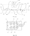
- Fig. 1A is an electrical schematic diagram illustrating a power system 100 according to an embodiment of the present invention.
- Fig. 1B is an electrical schematic diagram illustrating the circuitry of the power converter 200 and the inductor of filter 174 shown in Fig. 1A .
- a power system 100 may include a power converter 200, an input 110, switches 120 and 130, sensors 140 and 150 and a controller 300.
- Input 110 is coupled to a power source (e.g., a power generator or energy storage unit) that supplies power to the power system 100.
- the input 110 is electrically coupled to the power source side switch 120.
- the power converter 200 converts power between the power source coupled to input 110 and a grid that is coupled to the power system 100 at grid connection 160.
- power converter 200 is coupled to grid side switch 130, and the grid side switch 130 is coupled to a grid at the grid connection.
- Power conversion by power converter 200 may include AC/DC, DC/DC, AC/AC and DC/AC.
- the power converter 200 may be a bi-directional power inverter that converts power between DC and AC.
- the inverter 200 may convert power between DC and AC and may be controlled in different schemes. For example, in a grid-tied scheme, the power inverter is connecting to an established grid (e.g., a utility grid) and is operating in current source mode. In a grid forming scheme, the inverter is setting or creating the grid and is operating in voltage source mode.
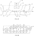
- the power converter may be a power converter 202 that is coupled between the power source 110 and another power converter 200, such as a power inverter 200.
- a power inverter 200 is coupled between the input 110 and the grid connection 160
- power converter 202 is coupled between the power inverter 200 and the input 110.
- the power converter 202 may be a DC/DC power converter that provides a voltage source to the power inverter 200. The flow of energy through the DC/DC power converter 202 is modulated to maintain an appropriate voltage source to the inverter 200.
- the power converter 202 may be an AC-DC converter 204 coupled to an AC source (e.g., a wind turbine) at input 110.
- the AC-DC converter 202 may then be coupled to a DC-AC inverter 200.
- the flow of energy through the AC-DC converter 202 is modulated to maintain an appropriate voltage source to the inverter 200, and the inverter 200 converts the power to AC suitable for grid connection 160.
- the power system 100 may also include additional elements such as fuse 170, manual disconnect switch 172, pre-charge circuit 122, LC filter 174, and grid circuit breaker 176.
- Fuse 170 is for disconnecting input 110 from the power converter 200 in the event of a fault.
- the manual disconnect switch 172 can be opened manually so that equipment in the power system 100 can be serviced.
- Pre-charnge circuit 122 may be used to pre-charge the DC bus.
- LC or resonant filter 174 may be configured to filter the AC output of power converter 200.
- the AC output of power converter 200 may usually contain harmonics and/or noises of other frequencies.
- Output LC filter 200 may be configured to filter out these harmonics and/or noises.
- Circuit breaker 176 can be manually opened so that equipment in power system 100 can be serviced, or circuit breaker 176 may open in an over current event to disconnect from the grid connected to grid connection 160.
- the grid connection 160 may be a connection to a micro-grid and/or a main (utility) grid.
- the micro-grid may include one or more distributed energy resources (distributed generators and energy storage units) and local loads within a local area.
- the power source connected to input 110 is one of the distributed energy resources (i.e. a generator or an energy storage unit) of the micro-grid.
- the loads can be one user (e.g., a utility customer), a grouping of several sites, or dispersed sites that operate in a coordinated fashion.
- the distributed generators may include reciprocating engine generators, micro-turbines, fuel cells, photovoltaic/solar panels, wind turbines, etc.
- the distributed energy resources of the micro-grid may be coordinated by a master (or user) controller 400.
- the master controller 400 may be physically separate from the controller 300 of the power system 100, may be included within the same box, or could be integrated with or included as part of the controller 300.
- the local loads of the micro-grid may be powered by the distributed energy resources of the micro-grid and/or the utility grid to which the micro-grid is connected.
- the power source connected to the input 110 may be an energy storage unit such as a battery (which could be a battery bank that includes plural batteries) that both stores and supplies energy from / to the grid.
- the input 110 is a DC input and the power converter 200 may be a 3-phase bi-directional power inverter that converts DC electric power on the DC side to AC electric power on the grid side and vice versa.
- the battery connected to input 110 may store excess energy not needed to power the local loads from one or more other distributed energy sources of the micro-grid.
- the battery may also store energy from the main utility grid. Energy stored in the battery connected to the input 110 may be supplied to local loads in the event of an outage at the main utility grid.
- the energy stored in the battery may also be used to provide more reliable and stable power when the micro-grid includes more unpredictable energy resources such as photovoltaic/solar panels and wind turbines.
- the power source side switch 120 may be an electromechanical switch such as a DC contactor
- the grid side switch 130 may be an electromechanical switch such as an AC contactor.
- the DC side switch 120 may, for example, be included within the battery container of the battery connected to input 110 or within the power converter 200. Alternatively, the switch 120 may be installed as part of the site external to both the battery and the power converter 200. In addition, the grid side switch 130 may be included within the power converter 200 or may be part of the site external to the power converter 200.
- the power converter 200 and the controller 300 together operate as a power conversion system for converting power between the power source and the grid.
- the controller 300 is responsible for the control, monitoring, and measurement of the power system 100 and may communicate with a master (or user) controller 400 in the event that the power system 100 is connected to a micro-grid that is coordinated by a master (or user) controller.
- the switches 120 and 130 may be controlled by the controller 300.
- the switches 120 and 130 may be electrically operated by the controller 300 through relay logic.
- the controller 300 uses the sensors 150 between switch 120 and grid connection 160 to monitor the voltage amplitude, frequency and phase of the grid, and the controller 300 uses the sensor 150 between filter 174 and power converter 200 to monitor the AC output current amplitude, frequency and phase of the power converter 200.
- the controller may also monitor DC input voltage through sensors 140.
- sensors 140 and 150 For sensors 140 and 150, 'V' and 'I' represent a voltage measurement and a current measurement, respectively, 'P' and 'PF' represent power by calculation and power factor by calculation, respectively, and 'Hz' represents a frequency measurement.
- the sensors 150 may include potential transformers, and the sensors 140 may include an isolated voltage monitor.
- the controller 300 may be located within the cabinet of the power converter 200 or may be a controller that is external to the power converter 200.
- the controller 200 may also include a plurality of controllers that communicate together.
- the controller 300 When the controller 300 is housed within the power converter 200, the controller 300 may be placed in an environment that is protected from the power electronics of the power converter 200 to mitigate electromagnetic noise interfering with the controller's 300 operation.
- the power electronics of the power converter 200 may be actively cooled by forced air and/or liquid, and may be controlled by controller 300 using fiber optic gating signals or electrical gating signals.
- Figs. 1B and 5B show embodiments of the power electronics of the power converter 200. Figs. 1B and 5B also show the inductor of the LC filter 174.
- the power converter 200 is a bi-directional power inverter; and in the embodiment of Fig. 5B , the power converter 202 is a DC/DC converter, and the power converter 200 is a power inverter.
- the power converters 200, 202 and 204 may include a plurality of semiconductor switches 210. Gates 212 of the semiconductor switches 210 receive gating signals when the power converters 200, 202 and 204 are gating (i.e., in a gating state).
- the gate signals are made up of a plurality of switching pulses for switching the semiconductor switches 210.
- the controller 300 controls the switching pattern of the semiconductor switches 210 to synchronize the output of the power converter 200 with the sine wave of the grid. In synchronizing the power converter 200 with the grid, the controller may control the semiconductor switches to match the phase, amplitude and/or frequency of the inverter to that of the grid.
- the semiconductor switches 210 may, for example, be insulated-gate bipolar transistors (IGBTs). Additional examples of semiconductor switches 210 include wide band-gap semiconductor devices such as silicon carbide and metal-oxide-semiconductor field-effect transistors (MOSFETs).
- One solution to the limitations imposed by the closure time of switches 120 and 130 is to leave the power system 100 connected to the power source and the grid, so that the switches 120 and 130 remain closed.
- the power converter 200 is then controlled by controller 300 to a set point of 0kW, meaning that the power converter 200 is controlled to output no power (i.e., 0 kW and 0 kVAR).
- the power system 100 can quickly respond to requests even when in an idle state.
- the power system 100 is able to quickly respond to a command to charge the battery (e.g., a sudden gust of wind) or discharge the battery (e.g., decrease in wind resource).
- a command to charge the battery e.g., a sudden gust of wind
- discharge the battery e.g., decrease in wind resource
- the power converter 200 is still gating even when the power converter 200 is controlled to output no power.
- the gates 212 are still receiving a gating signal, and thus the semiconductor switches 212 are still switching. Accordingly, the power system 100 is still incurring losses even though power is not being processed, and these losses are supplied by energy from the battery.
- the power converter's 200 cooling system may need to be run to remove the losses from the semiconductor switches 212.
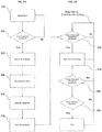
- Figs. 2A and 2B illustrate a method of controlling the power system 100 according to an embodiment of the present invention in which the power system 100 implements a plurality of operating modes while the power converter 200 is synchronized to the grid.
- Fig. 2A is a method for initializing the power converter 200, during which the power converter 200 is synchronized to the grid.
- Fig. 2B is a method of implementing the plurality of operating modes.
- Figs. 2A and 2B illustrate a method of implementing the plurality of operating modes in a bi-direction power inverter that is coupled between a DC power source and an AC grid.
- the input and grid connection are not limited to being a DC input and an AC grid connection.
- input 110 may be a DC or AC input and output may be a DC or AC grid connection.
- the power converter may be a power converter 202 that is connected to another power converter 200, such as in the example shown in Fig. 4A .
- the controller 300 may perform an analysis to determine whether the power converter 200 is ready to run (step 500). The analysis may include checking to ensure that there are no faults within the power system 100 and any safety parameters check out.
- the controller synchronizes the power converter 200 to the grid (step 520).
- the start command may be a command received from master controller 400, input by a user or autonomously generated by the controller 300.
- the controller 300 controls the switching pattern of the semiconductor switches 210 of the power converter 200 to synchronize the output of the power converter 200 with the sine wave of the grid.
- the controller may then control the power system to pre-charge the DC bus (step 530).
- the power system 100 gently brings the DC voltage up from the DC power source prior to closing the switch 120 connecting the power converter 200 to the input 110.
- the controller may then close the DC switch 120 so as to energize the battery with the DC port.
- the power converter 200 is ready to enter into active mode during which the power converter 200 is gating and can output an AC voltage.
- controller 300 may first determine whether the power converter 200 should be in active mode (power converter 200 is gating) or active standby mode (power converter 200 is not gating) (step 560).
- Step 560 may be an initial determination made by the controller 300 as to whether the power system 100 should be in the active mode or the active-standby mode.
- the controller 200 may initialize the power system 100 in the active mode, in which case step 560 would be a determination as to whether to remain in active mode or enter into active-standby mode.
- the controller 300 compares a power command to a predetermined deadband (or threshold) to determine whether the power command is within or outside of the deadband.
- the deadband may be set according to any number of ways, including, for example, being set by the user based on a requirement imposed by a regulating authority or being set as a result of a system impact study, which is a technical analysis of the local grid/power system.
- the power command may be a command for the power inverter 200 to supply/ absorb power, and the power command is the value that is compared to the deadband to determine whether to enter into the active mode or the active-standby mode.
- the power command may be a command received by the controller 300 from a master controller 400 or may be a command that is generated autonomously by controller 300 based, for example, on measurements taken from sensors. Furthermore, the power command may be a value calculated by the controller 300 based on measurements or values received from the master controller 400.
- the power command is preferably the amount of real power 'P' that the power converter 200 is commanded to supply or absorb, to/from the grid. However, it should be understood that the power command is not limited to real power, and the power command may be a real power command P or a reactive power command Q or even an apparent power command.
- the commands to controller 300 are real power (P) and reactive power (Q) commands within the rating of the inverter both independently and when added in quadrature to not exceed the apparent power rating of the inverter.
- the real power command P and reactive power command Q may be commands that are received by the controller 300 from a master controller 400 that is coordinating various energy resources of a micro-grid.
- the real power command P and reactive power command Q may be calculated based on various factors, such as the needs of the local loads and the output power of the energy resources of the micro-grid.
- the real P and reactive Q power commands may be autonomously generated by the controller 200 by, for example, calculating both the real and reactive power needs based on the measurements taken by sensors 150.
- the controller 300 controls the power converter 200 so that it is not gating, whereby the power system 100 enters into the active-standby mode (step 560 - NO). While the power system 100 is in the active-standby mode, the controller 300 continues to compare the power command to the deadband to determine if the power command falls outside the deadband. If the power command is outside the deadband, the controller 300 may control the power converter 200 so that it is gating, whereby the power system 100 enters into active mode (step 570). Once the power system 100 enters into the active mode, the controller 300 continues to monitor the power command to determine whether it falls within the deadband (step 580).
- the power system 100 enters into active-standby mode, during which the controller 300 controls the power system 200 so that it is not gating.
- the power system 100 may also employ hysteresis to prevent rapid switching between the active and active-standby modes.
- FIG. 6 illustrates a control scheme for comparing the power command to a deadband and entering/leaving a gating state.
- the semiconductor switches 212 may be controlled by pulse width modulated signals output from a pulse width modulator (PWM).
- PWM pulse width modulator
- the result of the comparison 620 between the power command and the deadband is input into one of the inputs of the AND gate.
- the other input of the AND gate receives one of the outputs of the pulse width modulator 600.
- the output of the comparison 620 is a logic high value (or 1), and the output of the AND gate 610 matches the output of the PWM 600.
- the output of the comparison 620 is a logic low (or 0) value, so that the IGBTs 210 do not receive the gating signal output by the PWM 600.
- the control scheme of FIG. 6 may be a comparison that happens within the firmware of controller 300, or may be part of the control logic implemented by controller 300.
- the method may also include a step of receiving a stop command (step 590), which may be a command from the master controller 400 or a command entered by a user. If a stop command is received (step 190), the power converter 200 stops operation.
- a stop command may be a command from the master controller 400 or a command entered by a user. If a stop command is received (step 190), the power converter 200 stops operation.
- the controller 300 controls power system 100 to synchronize the power converter 200 to the grid and to transition the power system 100 between the active mode and the active-standby mode.
- the controller 200 may be a field-programmable gate array (FPGA) or a digital signal processing (DSP) based controller. However, it should be understood that the controller 200 is not limited to these two types of controllers.
- control logic illustrates an exemplary embodiment in which controller is performing initialization of the power system 100 when the power system 100 is coupled to a DC power source at input 110.
- 'close dc_precharge' closes a relay to gently charge the dc bus from the power source.
- 'close dc_main' closes the dc switch 120.
- 'start grid_sync' synchronizes the power converter's controls system to the grid.
- 'start gating' starts switching of the semiconductor devices to emulate the grid voltage.
- 'close ac_contactor' closes the grid side switch 130.
- runPQ' indicates that the control system 100 is running in grid-tied mode.
- 'active_stdby OFF' initializes active standby to OFF.
- control logic illustrates an exemplary embodiment in which controller is comparing a power command to a threshold and operating the power converter 200 in the active and active standby modes.
- both real and reactive power commands are compared to an active standby turn off threshold.
- only one of the real and reactive power commands may be compared to the threshold, or an apparent power command calculated using real and reactive power commands may be compared to a deadband.
- the active-standby turnoff threshold to which the power command is compared includes an upper value and a lower value.
- the power command is compared to the lower threshold value when determining whether to enter into active standby mode, and the power command is compared to the upper threshold value when determining whether to enter into active mode. Having different upper and lower threshold values prevents rapid switching between the active and active-standby modes.
- 'sqrt(Pcmd_usr ⁇ 2+Qcmd_usr ⁇ 2)' is calculation of the apparent power command using a real power command and a reactive power command (in this exemplary embodiment, the real and reactive power commands are user power commands that may be received by controller 300 from master controller 400).
- the power command is compared to the deadband or threshold by the controller 300.
- Controller 300 receives the standby command from master controller 400 and controls the power converter 200 to be in active-standby mode.
- This embodiment may be advantageously used in a micro-grid in which master controller 400 is coordinating a variety of distributed energy resources. In such a case, it may be desirable for the master controller to directly instruct the power system 100 to enter into active-standby mode.
- Exemplary control logic for the controller 200 receiving a standby command directly from master controller 400 includes:
- 'start gating' is a start gating sequence to allow restarting of gating when coming back to active mode from a commanded active standby mode.
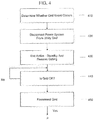
- FIG. 3 illustrates a method of controlling the power system 100 according to another embodiment of the present invention in which the power system 100 is connected to an energy storage unit, such as a battery, and implements a plurality of operating modes while the power converter is synchronized to the grid.
- the initialization method for the control system in this embodiment may be the same as that shown in Fig. 2A and will be omitted for brevity.
- Fig. 3 refers to an embodiment in which the power system 100 is coupled to an energy storage unit such as a battery at input 110.
- the power system 100 has both charge and discharge capabilities.
- separate thresholds are provided for charge mode and discharge mode. The separate thresholds are the upper and lower bounds of the deadband.
- the controller may first determine whether the power converter 200 should be in active mode (power converter 200 is gating) or active-standby mode (step 300, 310 and 312). Steps 300 310 and 312 may be an initial determination made by the controller 300 as to whether the power system 100 should be in the active mode or the active-standby mode. In an alternative embodiment, the controller 200 may initialize the power system 100 in the active mode, in which case steps 300, 310 and 312 would be a determination as to whether to remain in active mode or enter into active-standby mode.
- the controller determines whether the power command is positive or negative (step 300).
- a power command that is positive indicates discharge mode, and a power command that is negative indicates charge mode.
- the power command is compared to a first threshold (step 310).
- the controller 300 determines that the power system 100 should enter into the active-standby mode in which the power converter 200 is not gating (step 310 - NO), and the controller 300 continues to monitor the power command to determine whether it becomes lower than the first threshold. If the power command is lower than the first threshold, the controller 300 determines that the power system 100 should be in active mode and that gating should continue / begin (step 320).
- the controller 300 continues to monitor the power command to determine whether it is greater than the threshold and the power system 100 should enter into the active-standby mode (step 330 - NO).
- the method may also include a step of receiving a stop command (step 340), which may be a command from the master controller 400 or a command entered by a user. If a stop command is received, the power converter 200 stops operation.
- the power command is compared to a second threshold (step 312).
- the controller 300 determines that the power system 100 should enter into the active-standby mode in which the power converter 200 is not gating (step 312 - NO), and the controller 300 continues to monitor the power command to determine whether it becomes greater than the second threshold. If the power command is greater than the second threshold, the controller 300 determines that the power system 100 should be in active mode and that gating should continue / begin (step 322).
- the method may also include a step of receiving a stop command (step 342), which may be a command from the master controller 400 or a command entered by a user. If a stop command is received, the power converter stops operation.
- a stop command may be a command from the master controller 400 or a command entered by a user. If a stop command is received, the power converter stops operation.
- the following control logic illustrates an exemplary embodiment in which the controller is determining whether a power command is a charge command or a discharge command and comparing a power command to one of a first (charge) threshold and a second (discharge) threshold based on the determination.
- the power system 100 may be initialized in the active mode.
- each of the first and second thresholds include upper and lower values to prevent rapid switching between active and active-standby modes.
- the power command is a real power (P) command.
- 'if (Pcmd_usr ⁇ Pchg_up)' checks, when in charge mode, if the power/charge command is less than an upper value of a first (charge) threshold (this means that more charge is commanded since the charge convention is negative power).
- the controller compares active and/or reactive power commands to a threshold. These commands may be received by a master controller 400, or autonomously generated by the controller 300 itself.
- the following control logic illustrates an exemplary embodiment in which the active power command is set by controller 300 as a function of grid frequency (e.g., using a Hz-Watt function).
- the reactive power command may be set by controller 300 based on a Volt-Var type function.
- the grid frequency is compared to a frequency threshold to determine whether to enter into active mode or active stand by mode.
- the frequency threshold includes an upper value and a lower value, which form the upper and lower bounds of the deadband.
- controlP(FComp(GridFrequency)) is a control function that sets the power command as a function of grid frequency.
- Fcomp is a function that returns a power command based upon grid frequency (e.g., a Hz-Watt function).
- Fcomp can be any known function that returns such a power command, and can be a closed loop or open loop function.
- Fcomp may be a function in which the inverter responds with a predetermined power (e.g., 100% or -100% power) when the grid level is above or below a certain frequency.
- Fcomp may be an option that can be enabled by the power system or a user of the power system.
- the power converter 200 may operate in a normal grid tied mode unless Fcomp is enabled. elseif (GridFrequency > minGridF AND GridFrequency ⁇ maxGridF) refers to the situation where the grid frequency falls within the deadband, in which case the inverter is set to output 0 kW and active standby is turned on.
- the deadband/threshold is a frequency deadband/threshold.
- the grid frequency is compared to upper and lower limits of a deadband/threshold to determine whether to enter into active standby mode.
- this operation could be active simultaneously with any of the above control logic in which the power command is compared to a power deadband.
- the autonomously generated power command set using controlP(FComp(GridFrequency)) could be compared to a power threshold/deadband at the same time the grid frequency is compared to the frequency threshold/deadband.
- the controller 300 controls the power converter 200 to be in active or active-standby mode while the power converter 200 is synchronized to the grid.
- the power system 100 may be connected to the micro-grid and the utility grid at the grid connection 160.
- the utility grid may undergo a grid event, such as a power outage, where the power system 100 needs to disconnect from the grid and transition to a stand-alone (or islanded) mode during which the power source of the power system 100 is needed to power the local loads of the micro-grid.
- the controller may first determine that grid event occurs (step 400).
- the controller may determine that a grid even occurs by detecting a grid event using measurements taken by sensors 150.
- the grid event may, for example, be a power outage.
- the grid event may also be based on whether the grid voltage or frequency - which may be measured by sensors 150 - falls outside of predetermined bounds.
- the grid event may be detected by a master controller 400 that is coordinating the operations of the micro-grid.
- the master controller 400 may then send a control signal to controller 300 indicating that a grid event has occurred. Upon receipt of the control signal, controller 300 determines that a grid event has occurred.
- controller 300 sends a control signal to an islanding switch so that the islanding switch opens and disconnects the power system 100 from the grid (step 410).
- the islanding switch is a separate switch from the grid side switch 130.
- the grid side switch 130 disconnects the power converter 200 from the grid connection 160, which includes both the connection to the micro-grid and the utility grid. Differently, the islanding switch disconnects the power system 100 from the utility grid but not the micro-grid.
- master controller 400 may send the control signal to the islanding switch rather than controller 300.
- the controller 300 controls the power converter to begin gating (step 430) so that power can be supplied to the local loads.
- controller 300 determines that the grid is available (step 430)
- the power system 100 can reconnect to the grid (step 440).
- the controller 300 may again begin determining whether the power system 100 should be in the active mode or the active-standby mode, by, for example, reverting back to FIGS. 2B or 3 (step a).
- Exemplary control logic for the controller 300 operating the power converter 200 in the active and active standby modes in a power system 100 capable of operating in an islanding mode includes:
- the exemplary control logic adds 'grid_connect' to the power controller's control system.
- 'grid_connect' the controller 300 closes the islanding switch that connects the power system 100 to the utility grid.
- the control logic may include:
- 'grid_disconnect' opens the islanding switch to disconnect the power system 100 from the main utility grid.
- 'start gating' resumes gating if not already on (in other words, if the system is in active-standby, it exits active-standby and enters active mode).
- 'controlU(Ucmd_usr)' is a routine to control power converter output voltage to a voltage command.
- the voltage command and frequency command are commands for the output voltage and frequency of the power converter 200.
- these commands are user commands received by controller 300 from master controller 400.
- the voltage command and frequency command may also be autonomously generated by the controller 300.
- the voltage command and frequency command are for providing power to the microgrid.
- the user may wish to modify the output voltage and/or the frequency of the power converter 200 during voltage source mode. The user may wish to make such a change if there is a voltage drop in the local transmission such that the voltage at the load is less than the desired voltage.
- the disclosed embodiments provide an power system and method in which an power converter 200 can be operated in a plurality of modes when synchronized to a grid.
- the plurality of modes include an active-standby mode during which the power system's switches 120 and 130 are closed and the power converter 200 is synchronized to the grid, but the semiconductor switches of the power converter 200 are not gating.
- the power system's 100 controller 200 controls transition between the active-standby mode and active mode in an efficient manner by utilizing a deadband/threshold and comparing a power command to the deadband/threshold. Consistent with the disclosed embodiments of the present disclosure, the disclosed power system advantageously has a fast response time when transitioning from and idle state to a fully charging or discharging state.
- the disclosed power system 100 provides a fast response time without incurring the losses typical of having a power converter 200 synchronized to the grid while outputting no power.
- the disclosed embodiments provide a power system with a fast response time that conserves energy.
- a battery is given as an exemplary power source connected to input in the aforesaid embodiments discussed in connection with Figs. 2-4 and the aforesaid control logic, it should be understood the present invention is not limited to the use of a battery as a power source.
- embodiments of the present invention are suitable for any power source from which power is not constantly demanded or produced, such as a wind turbine or photovoltaic/solar panels.
Landscapes
- Engineering & Computer Science (AREA)
- Power Engineering (AREA)
- Business, Economics & Management (AREA)
- Emergency Management (AREA)
- Supply And Distribution Of Alternating Current (AREA)
- Inverter Devices (AREA)
- Direct Current Feeding And Distribution (AREA)
Claims (10)
- Stromversorgungssystem (100), umfassend einen Stromrichter (200) und eine Steuerung (300), wobei das Stromversorgungssystem (100) eine Vielzahl von Betriebsarten mit mindestens einem aktiven Modus und einem aktiven Bereitschaftsmodus aufweist, wobei
der Stromrichter (200) so konfiguriert ist, dass er eine Stromversorgung an eine gewünschte Ausgabe von mindestens einer Stromquelle (110) anpasst, wobei der Stromrichter (200) eine Vielzahl von Halbleiterschaltern (212) umfasst, und die mehreren Halbleiterschalter (212) so konfiguriert sind, dass sie ein Gate-Signal empfangen, wenn sich das Stromversorgungssystem (100) im aktiven Modus befindet, so dass sich der Stromrichter (200) in einem Gate-Zustand befindet, und die Steuerung (300) so konfiguriert ist, dass sie den Stromrichter (200) im aktiven Modus und im aktiven Bereitschaftsmodus steuert, wobei
die Steuerung (300) konfiguriert ist zum:Bestimmen, ob das Stromversorgungssystem (100) in den aktiven Bereitschaftsmodus eintreten soll, in dem der Stromrichter (200) mit einem Netz synchronisiert ist und sich in einem Nicht-Gate-Zustand befindet, undwenn bestimmt wird, dass das Stromversorgungssystem (100) in den aktiven Bereitschaftsmodus eintreten soll, den Stromrichter (200) so zu steuern, dass er sich in einem Nicht-Gate-Zustand befindet, so dass sich das Stromversorgungssystem (100) im aktiven Bereitschaftsmodus befindet,dadurch gekennzeichnet, dassdie Steuerung (300), die konfiguriert ist, um zu bestimmen, ob das Stromversorgungssystem (100)in den aktiven Bereitschaftsmodus eintreten soll, beinhaltet, dass die Steuerung (300) konfiguriert ist zum:Bestimmen, ob sich das Stromversorgungssystem (100) in einem Lade- oder Entladezustand befindet, indem bestimmt wird, ob ein Leistungsbefehl positiv oder negativ ist;wenn bestimmt wird, dass sich das Stromversorgungssystem (100) im Ladezustand befindet, Vergleichen des Leistungsbefehls mit einem ersten vorbestimmten Schwellenwert, und wenn bestimmt wird, dass der Leistungsbefehl höher als der vorbestimmte Schwellenwert ist, Bestimmen, dass sich das Stromversorgungssystem (100) in einem Ruhezustand befindet und in den aktiven Bereitschaftsmodus eintreten sollte;wenn bestimmt wird, dass sich das Stromversorgungssystem (100) im Entladezustand befindet, Vergleichen des Leistungsbefehls mit einem zweiten vorbestimmten Schwellenwert, und wenn bestimmt wird, dass der Leistungsbefehl niedriger als der zweite vorbestimmte Schwellenwert ist, Bestimmen, dass sich das Stromversorgungssystem (100) in dem Ruhezustand befindet und in den aktiven Bereitschaftsmodus eintreten sollte. - Stromversorgungssystem (100) nach Anspruch 1, ferner dadurch gekennzeichnet, dass das Stromversorgungssystem (100) ferner umfasst:einen stromquellenseitigen Schalter (120), der zwischen die mindestens eine Stromquelle (110) und den Stromrichter (200) geschaltet ist, und einen netzseitigen Schalter (130), der zwischen den Stromrichter (200) und das Netz geschaltet ist, wobeider stromquellenseitige Schalter und der netzseitige Schalter sowohl im aktiven Modus als auch im aktiven Bereitschaftsmodus geschlossen sind.
- Stromversorgungssystem (100) nach Anspruch 2, ferner dadurch gekennzeichnet, dass der Stromrichter (200) ein zwischen der Stromquelle (110) und dem Netz gekoppelter Wechselrichter (200) ist, und die Steuerung (300) ferner so konfiguriert ist, dass sie den Wechselrichter (200) initialisiert, wobei die Steuerung, die so konfiguriert ist, dass sie den Stromrichter (200) initialisiert, die Steuerung (300) beinhaltet, die konfiguriert ist zum:Aufladen eins DC-Busses von der mindestens einen Stromquelle(110);Schließen des stromquellenseitigen Schalters;Synchronisieren des Stromrichters (200) mit dem Netz;Eintreten des Stromrichters (200) in den Gate-Zustand;Schließen des netzseitigen Schalters, der zwischen den Stromrichter (200) und das Netz geschaltet ist, wodurch sich das Energiesystem (100) in einem netzgebundenen Modus befindet; undInitialisieren des aktiven Bereitschaftsmodus auf aus.
- Stromversorgungssystem (100) nach Anspruch 1, ferner dadurch gekennzeichnet, dass
die mindestens eine Stromquelle (110) eine Energiespeichereinheit beinhaltet und das Stromversorgungssystem (100) in einem Entladezustand, in dem die Steuerung (300) den Stromrichter (200) zum Entladen der Energiespeichereinheit steuert, einem Ladezustand, in dem die Steuerung (300) den Stromrichter (200) zum Laden der Energiespeichereinheit steuert, und einem Ruhezustand arbeitet, und
die Steuerung (300) bestimmt, dass das Stromversorgungssystem (100) in den aktiven Bereitschaftsmodus eintreten soll, wenn sich das Stromversorgungssystem (100) in einem Ruhezustand befindet. - Stromversorgungssystem (100) nach Anspruch 1, ferner dadurch gekennzeichnet, dass die Steuerung (300) so konfiguriert ist, dass sie bestimmt, dass das Stromversorgungssystem (100) in den aktiven Bereitschaftsmodus eintreten soll, wenn der Leistungsbefehl kleiner als ein vorbestimmter Schwellenwert ist, und dass das Steuersystem ferner konfiguriert ist zum:
nach dem Eintreten in den aktiven Bereitschaftsmodus, Bestimmen, ob das Stromversorgungssystem (100) den aktiven Bereitschaftsmodus verlassen und in den aktiven Modus eintreten soll, indem es den Leistungsbefehl weiterhin mit dem vorbestimmten Schwellenwert vergleicht, und wenn der Leistungsbefehl größer als der vorbestimmte Schwellenwert ist, den Stromrichter (200) so steuern, dass er sich im Gate-Zustand befindet. - Stromversorgungssystem (100) nach Anspruch 1, ferner dadurch gekennzeichnet, dass der erste vorbestimmte Schwellenwert einen oberen ersten Schwellenwert und einen unteren ersten Schwellenwert beinhaltet und der zweite vorbestimmte Schwellenwert einen oberen zweiten Schwellenwert und einen unteren zweiten Schwellenwert beinhaltet, und
wenn bestimmt wird, dass sich das Stromversorgungssystem (100) im Ladezustand befindet, der Leistungsbefehl mit dem unteren ersten Schwellenwert verglichen wird, um zu bestimmen, ob in den aktiven Bereitschaftsmodus eingetreten werden soll, und der Leistungsbefehl mit dem oberen ersten Schwellenwert verglichen wird, um zu bestimmen, ob in den aktiven Modus eingetreten werden soll, und
wenn bestimmt wird, dass sich das Stromversorgungssystem (100) im Entladezustand befindet, der Leistungsbefehl mit dem unteren zweiten Schwellenwert verglichen wird, um zu bestimmen, ob in den aktiven Bereitschaftsmodus eingetreten werden soll, und der Leistungsbefehl mit dem oberen zweiten Schwellenwert verglichen wird, um zu bestimmen, ob in den aktiven Modus eingetreten werden soll. - Stromversorgungssystem (100) nach Anspruch 1, ferner dadurch gekennzeichnet, dass die Steuerung (300) ferner so konfiguriert ist, dass sie einen Benutzerbefehl von einer Master-Steuerung (400) empfängt, um in den Bereitschaftsmodus einzutreten, und bestimmt, dass das Stromversorgungssystem in den aktiven Bereitschaftsmodus eintreten soll, wenn der Benutzerbefehl empfangen wird.
- Stromversorgungssystem (100) nach Anspruch 1, ferner dadurch gekennzeichnet, dass die Steuerung (300) so konfiguriert ist, dass sie einen AND-Betrieb des Gate-Signals und eines Ergebnisses durchführt, das auf dem Bestimmen beruht, ob das Stromversorgungssystem (100) in den aktiven Bereitschaftsmodus eintreten soll.
- Verfahren zum Steuern eines Stromversorgungssystem (100) mit einer Vielzahl von Betriebsarten, mit mindestens einem aktiven Modus, in dem ein Stromrichter (200) mit einem Netz synchronisiert ist und sich in einem Gate-Zustand befindet, in dem der Stromrichter (200) ein Gate-Signal empfängt, und einem aktiven Bereitschaftsmodus, in dem der Stromrichter (200) mit dem Netz synchronisiert ist und sich nicht in einem Gate-Zustand befindet, wobei das Verfahren umfasst:Vergleichen eines Leistungsbefehls mit einem vorgegebenen Schwellenwert und anhand des Vergleichs Bestimmen, ob das Stromversorgungssystem (100) in den aktiven Bereitschaftsmodus eintreten soll;wenn bestimmt wird, dass das Stromversorgungssystem (100) in den aktiven Bereitschaftsmodus eintreten und den Stromrichter (200) so steuern soll, dass er sich in einem Nicht-Gate-Zustand befindet,wobei das Vergleichen des Leistungsbefehls mit dem vorgegebenen Schwellenwert und anhand des Vergleichs Bestimmen, ob das Stromversorgungssystem (100) in den aktiven Bereitschaftsmodus eintreten soll umfasst:Bestimmen, ob sich das Stromversorgungssystem (100) in einem Lade- oder Entladezustand befindet, indem bestimmt wird, ob der Leistungsbefehl positiv oder negativ ist;wenn bestimmt wird, dass sich das Stromversorgungssystem (100) im Ladezustand befindet, Vergleichen des Leistungsbefehls mit einem ersten vorbestimmten Schwellenwert, und wenn bestimmt wird, dass der Leistungsbefehl höher als der vorbestimmte Schwellenwert ist, Bestimmen, dass das Stromversorgungssystem (100) in den aktiven Bereitschaftsmodus eintreten sollte;wenn bestimmt wird, dass sich das Stromversorgungssystem (100) im Entladezustand befindet, Vergleichen des Leistungsbefehls mit einem zweiten vorbestimmten Schwellenwert, und wenn bestimmt wird, dass der Leistungsbefehl niedriger als der zweite vorbestimmte Schwellenwert ist, Bestimmen, dass das Stromversorgungssystem (100) in den aktiven Bereitschaftsmodus eintreten sollte.
- Stromversorgungssystem (100) nach Anspruch 1, ferner dadurch gekennzeichnet, dass der Stromrichter (200) ein Wechselrichter (200) zur Stromumwandlung zwischen der Stromquelle (110) und dem Netz ist und die Steuerung (300) ferner konfiguriert zum:Synchronisieren des Wechselrichters (200) mit dem Netz.
Applications Claiming Priority (2)
| Application Number | Priority Date | Filing Date | Title |
|---|---|---|---|
| US201562188282P | 2015-07-02 | 2015-07-02 | |
| PCT/US2016/040004 WO2017004146A1 (en) | 2015-07-02 | 2016-06-29 | Power converter system having active standby mode and method of controlling the same |
Publications (2)
| Publication Number | Publication Date |
|---|---|
| EP3257129A1 EP3257129A1 (de) | 2017-12-20 |
| EP3257129B1 true EP3257129B1 (de) | 2020-11-04 |
Family
ID=56551555
Family Applications (1)
| Application Number | Title | Priority Date | Filing Date |
|---|---|---|---|
| EP16744971.9A Active EP3257129B1 (de) | 2015-07-02 | 2016-06-29 | Stromwandlersystem mit aktivem bereitschaftsmodus und verfahren zur steuerung eines solchen |
Country Status (9)
| Country | Link |
|---|---|
| US (2) | US9685852B2 (de) |
| EP (1) | EP3257129B1 (de) |
| JP (1) | JP6419989B2 (de) |
| KR (1) | KR101933579B1 (de) |
| CN (1) | CN107636927B (de) |
| AU (1) | AU2016285855B2 (de) |
| NZ (1) | NZ734663A (de) |
| WO (1) | WO2017004146A1 (de) |
| ZA (1) | ZA201705748B (de) |
Cited By (1)
| Publication number | Priority date | Publication date | Assignee | Title |
|---|---|---|---|---|
| WO2025172165A1 (de) * | 2024-02-16 | 2025-08-21 | Sma Solar Technology Ag | Verfahren zum betrieb eines wechselrichters für eine batterie und wechselrichter zur durchführung des verfahrens |
Families Citing this family (20)
| Publication number | Priority date | Publication date | Assignee | Title |
|---|---|---|---|---|
| CN107231013B (zh) * | 2016-05-24 | 2019-01-15 | 华为技术有限公司 | 一种充电的方法、终端、充电器和系统 |
| CN110622379A (zh) * | 2017-03-16 | 2019-12-27 | 伊格纳西奥·华雷斯 | 微型逆变器和控制器 |
| WO2018211658A1 (ja) * | 2017-05-18 | 2018-11-22 | 三菱電機株式会社 | 無効電力補償装置およびその制御方法 |
| US10389134B2 (en) | 2017-06-21 | 2019-08-20 | Katerra, Inc. | Electrical power distribution system and method |
| KR102261258B1 (ko) * | 2017-08-14 | 2021-06-07 | 다이너파워 컴퍼니 엘엘씨 | 양방향 저장 및 재생 가능한 전력 변환기를 위한 방법 및 장치 |
| DE102017127081B4 (de) | 2017-11-17 | 2019-05-29 | Sma Solar Technology Ag | Verfahren zum Schwarzstart einer Energieversorgungseinrichtung, bidirektionaler Wechselrichter und Energieversorgungseinrichtung mit einem bidirektionalen Wechselrichter |
| US10790662B2 (en) | 2018-04-03 | 2020-09-29 | Katerra, Inc. | DC bus-based electrical power router utilizing multiple configurable bidirectional AC/DC converters |
| US10897138B2 (en) | 2018-04-12 | 2021-01-19 | Katerra, Inc. | Method and apparatus for dynamic electrical load sensing and line to load switching |
| CN108615724B (zh) * | 2018-05-08 | 2020-05-22 | 西安交通大学 | 一种微感型igbt并联均流结构 |
| AU2019321446B2 (en) * | 2018-08-14 | 2024-06-20 | Generac Power Systems, Inc. | Two-terminal protective device using parasitic energy harvesting |
| CN112956124A (zh) | 2018-09-12 | 2021-06-11 | 伊格纳西奥·华雷斯 | 微型逆变器及控制器 |
| CN109616904A (zh) * | 2018-10-25 | 2019-04-12 | 深圳市科陆电子科技股份有限公司 | 用于储能集装箱设备的升压装置和储能集装箱设备 |
| AU2019435207B2 (en) * | 2019-03-15 | 2024-12-19 | Ge Grid Solutions Llc | Customizable power converter and customizable power conversion system |
| AU2020347098A1 (en) * | 2019-09-09 | 2022-04-28 | Elexsys Ip Pty Ltd | Electrical power distribution system |
| JP2023530952A (ja) * | 2020-06-15 | 2023-07-20 | エンフェーズ エナジー インコーポレイテッド | 開回路検出を使用する単独運転可能なインバータの高速シャットダウンのための方法および機器 |
| US12077056B2 (en) | 2020-07-14 | 2024-09-03 | Cummins Inc. | Bidirectional electric vehicle charging with multi-phase machines |
| JP6928731B1 (ja) * | 2020-12-24 | 2021-09-01 | 三菱電機株式会社 | 蓄電システムおよび系統制御システム |
| EP4057481A1 (de) * | 2021-03-08 | 2022-09-14 | Bloom Energy Corporation | Mikronetz mit dualem mikronetzwechselrichter und verfahren zur lastverwaltung |
| US11990750B2 (en) * | 2021-07-08 | 2024-05-21 | University Of Vermont And State Agricultural College | Decentralized frequency control with packet-based energy management |
| CN116569436A (zh) * | 2021-12-02 | 2023-08-08 | 东芝三菱电机产业系统株式会社 | 无功功率控制装置、无功功率控制方法以及无功功率控制程序 |
Citations (1)
| Publication number | Priority date | Publication date | Assignee | Title |
|---|---|---|---|---|
| US20120026769A1 (en) * | 2010-07-29 | 2012-02-02 | General Electric Company | Photovoltaic inverter system and method of starting same at high open-circuit voltage |
Family Cites Families (24)
| Publication number | Priority date | Publication date | Assignee | Title |
|---|---|---|---|---|
| US7183667B2 (en) * | 2003-12-19 | 2007-02-27 | Square D Company | Method and apparatus for power inverter synchronization |
| US9093862B2 (en) * | 2009-01-16 | 2015-07-28 | Zbb Energy Corporation | Method and apparatus for controlling a hybrid power system |
| US8687385B2 (en) * | 2009-11-25 | 2014-04-01 | Triune Ip Llc | Low power converter |
| US9502904B2 (en) * | 2010-03-23 | 2016-11-22 | Eaton Corporation | Power conversion system and method providing maximum efficiency of power conversion for a photovoltaic system, and photovoltaic system employing a photovoltaic array and an energy storage device |
| US8279649B2 (en) * | 2010-10-11 | 2012-10-02 | Solarbridge Technologies, Inc. | Apparatus and method for controlling a power inverter |
| WO2012062375A1 (en) * | 2010-11-12 | 2012-05-18 | Sma Solar Technology Ag | Power inverter for feeding electric energy from a dc power generator into an ac grid with two power lines |
| CN103348131B (zh) * | 2010-12-10 | 2016-06-01 | 维斯塔斯风力系统集团公司 | 操作风力涡轮机的方法及与其适应的系统 |
| US8854004B2 (en) * | 2011-01-12 | 2014-10-07 | Samsung Sdi Co., Ltd. | Energy storage system and controlling method thereof |
| US9136709B2 (en) * | 2011-10-26 | 2015-09-15 | General Electric Company | Methods and systems for selectively coupling a power conversion system to an electrical grid |
| IN2014CN03545A (de) * | 2011-10-28 | 2015-07-03 | Gen Electric | |
| US9478989B2 (en) * | 2012-01-17 | 2016-10-25 | Infineon Technologies Austria Ag | Power converter circuit with AC output |
| KR101835662B1 (ko) * | 2012-01-17 | 2018-03-08 | 인피니언 테크놀로지스 오스트리아 아게 | 전력 컨버터 회로, 전력 공급 시스템 및 방법 |
| EP2621070A1 (de) * | 2012-01-26 | 2013-07-31 | Siemens Aktiengesellschaft | Verfahren und Anordnung für den Betrieb eines Windturbinenwandlers |
| US20130300196A1 (en) * | 2012-05-09 | 2013-11-14 | Dynapower Company, Llc | Multi-port inverter/converter system for dynamic micro-grid applications |
| CA2883369A1 (en) * | 2012-08-30 | 2014-03-06 | General Electric Company | System and method for protecting electrical machines |
| US9837824B2 (en) * | 2012-09-03 | 2017-12-05 | Vestas Wind Systems A/S | Connection system for power generation system with DC output |
| JP5764750B2 (ja) * | 2012-11-16 | 2015-08-19 | パナソニックIpマネジメント株式会社 | リレー動作設定装置、パワーコンディショナ及び分散型電源システム |
| TWI509403B (zh) * | 2013-02-18 | 2015-11-21 | Compal Electronics Inc | 電子裝置 |
| JP6082886B2 (ja) * | 2013-02-22 | 2017-02-22 | 株式会社高砂製作所 | 電力調整装置及び電力調整方法 |
| CN103248067B (zh) * | 2013-04-27 | 2016-03-02 | 京东方科技集团股份有限公司 | 光伏并网逆变器的低压穿越控制方法及装置 |
| US11289940B2 (en) | 2013-06-14 | 2022-03-29 | Abb Schweiz Ag | Systems and methods for multi-use multi-mode ups |
| JP6082667B2 (ja) * | 2013-07-03 | 2017-02-15 | 株式会社三社電機製作所 | パワーコンディショナー |
| US9912150B2 (en) * | 2013-07-10 | 2018-03-06 | Mitsubishi Electric Corporation | Power control system |
| CN104362665B (zh) * | 2014-09-28 | 2017-01-25 | 北京索英电气技术有限公司 | 一种微电网离网切换到并网的控制系统及控制方法 |
-
2016
- 2016-06-29 EP EP16744971.9A patent/EP3257129B1/de active Active
- 2016-06-29 CN CN201680013041.1A patent/CN107636927B/zh active Active
- 2016-06-29 KR KR1020177024575A patent/KR101933579B1/ko active Active
- 2016-06-29 AU AU2016285855A patent/AU2016285855B2/en active Active
- 2016-06-29 WO PCT/US2016/040004 patent/WO2017004146A1/en not_active Ceased
- 2016-06-29 JP JP2017546896A patent/JP6419989B2/ja active Active
- 2016-06-29 NZ NZ734663A patent/NZ734663A/en unknown
- 2016-06-29 US US15/197,007 patent/US9685852B2/en active Active
-
2017
- 2017-05-18 US US15/598,435 patent/US10243444B2/en active Active
- 2017-08-23 ZA ZA2017/05748A patent/ZA201705748B/en unknown
Patent Citations (1)
| Publication number | Priority date | Publication date | Assignee | Title |
|---|---|---|---|---|
| US20120026769A1 (en) * | 2010-07-29 | 2012-02-02 | General Electric Company | Photovoltaic inverter system and method of starting same at high open-circuit voltage |
Cited By (1)
| Publication number | Priority date | Publication date | Assignee | Title |
|---|---|---|---|---|
| WO2025172165A1 (de) * | 2024-02-16 | 2025-08-21 | Sma Solar Technology Ag | Verfahren zum betrieb eines wechselrichters für eine batterie und wechselrichter zur durchführung des verfahrens |
Also Published As
| Publication number | Publication date |
|---|---|
| AU2016285855A1 (en) | 2017-08-24 |
| EP3257129A1 (de) | 2017-12-20 |
| AU2016285855B2 (en) | 2018-04-19 |
| CN107636927A (zh) | 2018-01-26 |
| KR20170129717A (ko) | 2017-11-27 |
| JP2018519774A (ja) | 2018-07-19 |
| CN107636927B (zh) | 2020-12-25 |
| WO2017004146A1 (en) | 2017-01-05 |
| ZA201705748B (en) | 2018-11-28 |
| US9685852B2 (en) | 2017-06-20 |
| NZ734663A (en) | 2021-12-24 |
| JP6419989B2 (ja) | 2018-11-07 |
| US20170005564A1 (en) | 2017-01-05 |
| US10243444B2 (en) | 2019-03-26 |
| US20170358980A1 (en) | 2017-12-14 |
| KR101933579B1 (ko) | 2019-04-05 |
Similar Documents
| Publication | Publication Date | Title |
|---|---|---|
| EP3257129B1 (de) | Stromwandlersystem mit aktivem bereitschaftsmodus und verfahren zur steuerung eines solchen | |
| KR101884621B1 (ko) | 다수의 그리드 연계형 전력 변환기의 단독 운전 | |
| EP3090318B1 (de) | Steuerung eines mikronetzes | |
| KR102281862B1 (ko) | 그리드 형성 모드에서 복수의 전력 컨버터를 시동하는 방법 및 전력 시스템 | |
| AU2010284447A1 (en) | AC connected modules with line frequency or voltage variation pattern for energy control | |
| CN105470997B (zh) | 一种微电网控制系统 | |
| AU2013394122A1 (en) | Controlling power in a micro-grid | |
| US20230108060A1 (en) | System and method for providing uninterruptible power supply using one or more energy sources | |
| Frack et al. | Control-strategy design for frequency control in autonomous smart microgrids | |
| Liu et al. | Switching performance optimization for a hybrid AC/DC microgrid using an improved VSG control strategy | |
| NZ734661B2 (en) | Islanding a plurality of grid tied power converters |
Legal Events
| Date | Code | Title | Description |
|---|---|---|---|
| STAA | Information on the status of an ep patent application or granted ep patent |
Free format text: STATUS: THE INTERNATIONAL PUBLICATION HAS BEEN MADE |
|
| PUAI | Public reference made under article 153(3) epc to a published international application that has entered the european phase |
Free format text: ORIGINAL CODE: 0009012 |
|
| STAA | Information on the status of an ep patent application or granted ep patent |
Free format text: STATUS: REQUEST FOR EXAMINATION WAS MADE |
|
| 17P | Request for examination filed |
Effective date: 20170915 |
|
| AK | Designated contracting states |
Kind code of ref document: A1 Designated state(s): AL AT BE BG CH CY CZ DE DK EE ES FI FR GB GR HR HU IE IS IT LI LT LU LV MC MK MT NL NO PL PT RO RS SE SI SK SM TR |
|
| AX | Request for extension of the european patent |
Extension state: BA ME |
|
| STAA | Information on the status of an ep patent application or granted ep patent |
Free format text: STATUS: EXAMINATION IS IN PROGRESS |
|
| 17Q | First examination report despatched |
Effective date: 20180320 |
|
| DAV | Request for validation of the european patent (deleted) | ||
| DAX | Request for extension of the european patent (deleted) | ||
| GRAP | Despatch of communication of intention to grant a patent |
Free format text: ORIGINAL CODE: EPIDOSNIGR1 |
|
| STAA | Information on the status of an ep patent application or granted ep patent |
Free format text: STATUS: GRANT OF PATENT IS INTENDED |
|
| INTG | Intention to grant announced |
Effective date: 20200529 |
|
| GRAS | Grant fee paid |
Free format text: ORIGINAL CODE: EPIDOSNIGR3 |
|
| GRAA | (expected) grant |
Free format text: ORIGINAL CODE: 0009210 |
|
| STAA | Information on the status of an ep patent application or granted ep patent |
Free format text: STATUS: THE PATENT HAS BEEN GRANTED |
|
| AK | Designated contracting states |
Kind code of ref document: B1 Designated state(s): AL AT BE BG CH CY CZ DE DK EE ES FI FR GB GR HR HU IE IS IT LI LT LU LV MC MK MT NL NO PL PT RO RS SE SI SK SM TR |
|
| REG | Reference to a national code |
Ref country code: GB Ref legal event code: FG4D |
|
| REG | Reference to a national code |
Ref country code: CH Ref legal event code: EP |
|
| REG | Reference to a national code |
Ref country code: AT Ref legal event code: REF Ref document number: 1332069 Country of ref document: AT Kind code of ref document: T Effective date: 20201115 |
|
| REG | Reference to a national code |
Ref country code: DE Ref legal event code: R096 Ref document number: 602016047166 Country of ref document: DE |
|
| REG | Reference to a national code |
Ref country code: IE Ref legal event code: FG4D |
|
| REG | Reference to a national code |
Ref country code: NL Ref legal event code: FP |
|
| REG | Reference to a national code |
Ref country code: AT Ref legal event code: MK05 Ref document number: 1332069 Country of ref document: AT Kind code of ref document: T Effective date: 20201104 |
|
| PG25 | Lapsed in a contracting state [announced via postgrant information from national office to epo] |
Ref country code: RS Free format text: LAPSE BECAUSE OF FAILURE TO SUBMIT A TRANSLATION OF THE DESCRIPTION OR TO PAY THE FEE WITHIN THE PRESCRIBED TIME-LIMIT Effective date: 20201104 Ref country code: PT Free format text: LAPSE BECAUSE OF FAILURE TO SUBMIT A TRANSLATION OF THE DESCRIPTION OR TO PAY THE FEE WITHIN THE PRESCRIBED TIME-LIMIT Effective date: 20210304 Ref country code: NO Free format text: LAPSE BECAUSE OF FAILURE TO SUBMIT A TRANSLATION OF THE DESCRIPTION OR TO PAY THE FEE WITHIN THE PRESCRIBED TIME-LIMIT Effective date: 20210204 Ref country code: FI Free format text: LAPSE BECAUSE OF FAILURE TO SUBMIT A TRANSLATION OF THE DESCRIPTION OR TO PAY THE FEE WITHIN THE PRESCRIBED TIME-LIMIT Effective date: 20201104 Ref country code: GR Free format text: LAPSE BECAUSE OF FAILURE TO SUBMIT A TRANSLATION OF THE DESCRIPTION OR TO PAY THE FEE WITHIN THE PRESCRIBED TIME-LIMIT Effective date: 20210205 |
|
| PG25 | Lapsed in a contracting state [announced via postgrant information from national office to epo] |
Ref country code: SE Free format text: LAPSE BECAUSE OF FAILURE TO SUBMIT A TRANSLATION OF THE DESCRIPTION OR TO PAY THE FEE WITHIN THE PRESCRIBED TIME-LIMIT Effective date: 20201104 Ref country code: BG Free format text: LAPSE BECAUSE OF FAILURE TO SUBMIT A TRANSLATION OF THE DESCRIPTION OR TO PAY THE FEE WITHIN THE PRESCRIBED TIME-LIMIT Effective date: 20210204 Ref country code: PL Free format text: LAPSE BECAUSE OF FAILURE TO SUBMIT A TRANSLATION OF THE DESCRIPTION OR TO PAY THE FEE WITHIN THE PRESCRIBED TIME-LIMIT Effective date: 20201104 Ref country code: IS Free format text: LAPSE BECAUSE OF FAILURE TO SUBMIT A TRANSLATION OF THE DESCRIPTION OR TO PAY THE FEE WITHIN THE PRESCRIBED TIME-LIMIT Effective date: 20210304 Ref country code: LV Free format text: LAPSE BECAUSE OF FAILURE TO SUBMIT A TRANSLATION OF THE DESCRIPTION OR TO PAY THE FEE WITHIN THE PRESCRIBED TIME-LIMIT Effective date: 20201104 Ref country code: ES Free format text: LAPSE BECAUSE OF FAILURE TO SUBMIT A TRANSLATION OF THE DESCRIPTION OR TO PAY THE FEE WITHIN THE PRESCRIBED TIME-LIMIT Effective date: 20201104 Ref country code: AT Free format text: LAPSE BECAUSE OF FAILURE TO SUBMIT A TRANSLATION OF THE DESCRIPTION OR TO PAY THE FEE WITHIN THE PRESCRIBED TIME-LIMIT Effective date: 20201104 |
|
| REG | Reference to a national code |
Ref country code: LT Ref legal event code: MG9D |
|
| PG25 | Lapsed in a contracting state [announced via postgrant information from national office to epo] |
Ref country code: HR Free format text: LAPSE BECAUSE OF FAILURE TO SUBMIT A TRANSLATION OF THE DESCRIPTION OR TO PAY THE FEE WITHIN THE PRESCRIBED TIME-LIMIT Effective date: 20201104 |
|
| PG25 | Lapsed in a contracting state [announced via postgrant information from national office to epo] |
Ref country code: SK Free format text: LAPSE BECAUSE OF FAILURE TO SUBMIT A TRANSLATION OF THE DESCRIPTION OR TO PAY THE FEE WITHIN THE PRESCRIBED TIME-LIMIT Effective date: 20201104 Ref country code: RO Free format text: LAPSE BECAUSE OF FAILURE TO SUBMIT A TRANSLATION OF THE DESCRIPTION OR TO PAY THE FEE WITHIN THE PRESCRIBED TIME-LIMIT Effective date: 20201104 Ref country code: LT Free format text: LAPSE BECAUSE OF FAILURE TO SUBMIT A TRANSLATION OF THE DESCRIPTION OR TO PAY THE FEE WITHIN THE PRESCRIBED TIME-LIMIT Effective date: 20201104 Ref country code: SM Free format text: LAPSE BECAUSE OF FAILURE TO SUBMIT A TRANSLATION OF THE DESCRIPTION OR TO PAY THE FEE WITHIN THE PRESCRIBED TIME-LIMIT Effective date: 20201104 Ref country code: CZ Free format text: LAPSE BECAUSE OF FAILURE TO SUBMIT A TRANSLATION OF THE DESCRIPTION OR TO PAY THE FEE WITHIN THE PRESCRIBED TIME-LIMIT Effective date: 20201104 Ref country code: EE Free format text: LAPSE BECAUSE OF FAILURE TO SUBMIT A TRANSLATION OF THE DESCRIPTION OR TO PAY THE FEE WITHIN THE PRESCRIBED TIME-LIMIT Effective date: 20201104 |
|
| REG | Reference to a national code |
Ref country code: DE Ref legal event code: R097 Ref document number: 602016047166 Country of ref document: DE |
|
| PG25 | Lapsed in a contracting state [announced via postgrant information from national office to epo] |
Ref country code: DK Free format text: LAPSE BECAUSE OF FAILURE TO SUBMIT A TRANSLATION OF THE DESCRIPTION OR TO PAY THE FEE WITHIN THE PRESCRIBED TIME-LIMIT Effective date: 20201104 |
|
| PLBE | No opposition filed within time limit |
Free format text: ORIGINAL CODE: 0009261 |
|
| STAA | Information on the status of an ep patent application or granted ep patent |
Free format text: STATUS: NO OPPOSITION FILED WITHIN TIME LIMIT |
|
| 26N | No opposition filed |
Effective date: 20210805 |
|
| PG25 | Lapsed in a contracting state [announced via postgrant information from national office to epo] |
Ref country code: AL Free format text: LAPSE BECAUSE OF FAILURE TO SUBMIT A TRANSLATION OF THE DESCRIPTION OR TO PAY THE FEE WITHIN THE PRESCRIBED TIME-LIMIT Effective date: 20201104 |
|
| PG25 | Lapsed in a contracting state [announced via postgrant information from national office to epo] |
Ref country code: SI Free format text: LAPSE BECAUSE OF FAILURE TO SUBMIT A TRANSLATION OF THE DESCRIPTION OR TO PAY THE FEE WITHIN THE PRESCRIBED TIME-LIMIT Effective date: 20201104 |
|
| PG25 | Lapsed in a contracting state [announced via postgrant information from national office to epo] |
Ref country code: MC Free format text: LAPSE BECAUSE OF FAILURE TO SUBMIT A TRANSLATION OF THE DESCRIPTION OR TO PAY THE FEE WITHIN THE PRESCRIBED TIME-LIMIT Effective date: 20201104 |
|
| REG | Reference to a national code |
Ref country code: CH Ref legal event code: PL |
|
| REG | Reference to a national code |
Ref country code: BE Ref legal event code: MM Effective date: 20210630 |
|
| PG25 | Lapsed in a contracting state [announced via postgrant information from national office to epo] |
Ref country code: LU Free format text: LAPSE BECAUSE OF NON-PAYMENT OF DUE FEES Effective date: 20210629 |
|
| PG25 | Lapsed in a contracting state [announced via postgrant information from national office to epo] |
Ref country code: LI Free format text: LAPSE BECAUSE OF NON-PAYMENT OF DUE FEES Effective date: 20210630 Ref country code: CH Free format text: LAPSE BECAUSE OF NON-PAYMENT OF DUE FEES Effective date: 20210630 |
|
| PG25 | Lapsed in a contracting state [announced via postgrant information from national office to epo] |
Ref country code: IS Free format text: LAPSE BECAUSE OF FAILURE TO SUBMIT A TRANSLATION OF THE DESCRIPTION OR TO PAY THE FEE WITHIN THE PRESCRIBED TIME-LIMIT Effective date: 20210304 |
|
| PG25 | Lapsed in a contracting state [announced via postgrant information from national office to epo] |
Ref country code: BE Free format text: LAPSE BECAUSE OF NON-PAYMENT OF DUE FEES Effective date: 20210630 |
|
| PG25 | Lapsed in a contracting state [announced via postgrant information from national office to epo] |
Ref country code: HU Free format text: LAPSE BECAUSE OF FAILURE TO SUBMIT A TRANSLATION OF THE DESCRIPTION OR TO PAY THE FEE WITHIN THE PRESCRIBED TIME-LIMIT; INVALID AB INITIO Effective date: 20160629 |
|
| PG25 | Lapsed in a contracting state [announced via postgrant information from national office to epo] |
Ref country code: CY Free format text: LAPSE BECAUSE OF FAILURE TO SUBMIT A TRANSLATION OF THE DESCRIPTION OR TO PAY THE FEE WITHIN THE PRESCRIBED TIME-LIMIT Effective date: 20201104 |
|
| P01 | Opt-out of the competence of the unified patent court (upc) registered |
Effective date: 20230708 |
|
| PG25 | Lapsed in a contracting state [announced via postgrant information from national office to epo] |
Ref country code: MK Free format text: LAPSE BECAUSE OF FAILURE TO SUBMIT A TRANSLATION OF THE DESCRIPTION OR TO PAY THE FEE WITHIN THE PRESCRIBED TIME-LIMIT Effective date: 20201104 |
|
| PG25 | Lapsed in a contracting state [announced via postgrant information from national office to epo] |
Ref country code: MT Free format text: LAPSE BECAUSE OF FAILURE TO SUBMIT A TRANSLATION OF THE DESCRIPTION OR TO PAY THE FEE WITHIN THE PRESCRIBED TIME-LIMIT Effective date: 20201104 |
|
| PGFP | Annual fee paid to national office [announced via postgrant information from national office to epo] |
Ref country code: DE Payment date: 20250627 Year of fee payment: 10 |
|
| PGFP | Annual fee paid to national office [announced via postgrant information from national office to epo] |
Ref country code: GB Payment date: 20250627 Year of fee payment: 10 |
|
| PGFP | Annual fee paid to national office [announced via postgrant information from national office to epo] |
Ref country code: NL Payment date: 20250626 Year of fee payment: 10 |
|
| PGFP | Annual fee paid to national office [announced via postgrant information from national office to epo] |
Ref country code: FR Payment date: 20250625 Year of fee payment: 10 |
|
| PGFP | Annual fee paid to national office [announced via postgrant information from national office to epo] |
Ref country code: IE Payment date: 20250627 Year of fee payment: 10 |
|
| PGFP | Annual fee paid to national office [announced via postgrant information from national office to epo] |
Ref country code: IT Payment date: 20250619 Year of fee payment: 10 |
|
| PG25 | Lapsed in a contracting state [announced via postgrant information from national office to epo] |
Ref country code: TR Free format text: LAPSE BECAUSE OF FAILURE TO SUBMIT A TRANSLATION OF THE DESCRIPTION OR TO PAY THE FEE WITHIN THE PRESCRIBED TIME-LIMIT Effective date: 20201104 |