EP3257448B1 - Fixation chirurgicale avec attaches chirurgicales en forme de w - Google Patents
Fixation chirurgicale avec attaches chirurgicales en forme de w Download PDFInfo
- Publication number
- EP3257448B1 EP3257448B1 EP17175562.2A EP17175562A EP3257448B1 EP 3257448 B1 EP3257448 B1 EP 3257448B1 EP 17175562 A EP17175562 A EP 17175562A EP 3257448 B1 EP3257448 B1 EP 3257448B1
- Authority
- EP
- European Patent Office
- Prior art keywords
- fastener
- end effector
- arms
- anvil
- backspan
- Prior art date
- Legal status (The legal status is an assumption and is not a legal conclusion. Google has not performed a legal analysis and makes no representation as to the accuracy of the status listed.)
- Not-in-force
Links
Images




Classifications
-
- A—HUMAN NECESSITIES
- A61—MEDICAL OR VETERINARY SCIENCE; HYGIENE
- A61N—ELECTROTHERAPY; MAGNETOTHERAPY; RADIATION THERAPY; ULTRASOUND THERAPY
- A61N5/00—Radiation therapy
- A61N5/10—X-ray therapy; Gamma-ray therapy; Particle-irradiation therapy
- A61N5/1001—X-ray therapy; Gamma-ray therapy; Particle-irradiation therapy using radiation sources introduced into or applied onto the body; brachytherapy
- A61N5/1007—Arrangements or means for the introduction of sources into the body
-
- A—HUMAN NECESSITIES
- A61—MEDICAL OR VETERINARY SCIENCE; HYGIENE
- A61B—DIAGNOSIS; SURGERY; IDENTIFICATION
- A61B17/00—Surgical instruments, devices or methods
- A61B17/068—Surgical staplers, e.g. containing multiple staples or clamps
-
- A—HUMAN NECESSITIES
- A61—MEDICAL OR VETERINARY SCIENCE; HYGIENE
- A61N—ELECTROTHERAPY; MAGNETOTHERAPY; RADIATION THERAPY; ULTRASOUND THERAPY
- A61N5/00—Radiation therapy
- A61N5/10—X-ray therapy; Gamma-ray therapy; Particle-irradiation therapy
- A61N5/1001—X-ray therapy; Gamma-ray therapy; Particle-irradiation therapy using radiation sources introduced into or applied onto the body; brachytherapy
-
- A—HUMAN NECESSITIES
- A61—MEDICAL OR VETERINARY SCIENCE; HYGIENE
- A61B—DIAGNOSIS; SURGERY; IDENTIFICATION
- A61B17/00—Surgical instruments, devices or methods
- A61B17/064—Surgical staples, i.e. penetrating the tissue
- A61B17/0644—Surgical staples, i.e. penetrating the tissue penetrating the tissue, deformable to closed position
-
- A—HUMAN NECESSITIES
- A61—MEDICAL OR VETERINARY SCIENCE; HYGIENE
- A61B—DIAGNOSIS; SURGERY; IDENTIFICATION
- A61B17/00—Surgical instruments, devices or methods
- A61B17/068—Surgical staplers, e.g. containing multiple staples or clamps
- A61B17/0682—Surgical staplers, e.g. containing multiple staples or clamps for applying U-shaped staples or clamps, e.g. without a forming anvil
- A61B17/0684—Surgical staplers, e.g. containing multiple staples or clamps for applying U-shaped staples or clamps, e.g. without a forming anvil having a forming anvil staying above the tissue during stapling
-
- A—HUMAN NECESSITIES
- A61—MEDICAL OR VETERINARY SCIENCE; HYGIENE
- A61B—DIAGNOSIS; SURGERY; IDENTIFICATION
- A61B17/00—Surgical instruments, devices or methods
- A61B17/10—Surgical instruments, devices or methods for applying or removing wound clamps, e.g. containing only one clamp or staple; Wound clamp magazines
- A61B17/105—Wound clamp magazines
-
- A—HUMAN NECESSITIES
- A61—MEDICAL OR VETERINARY SCIENCE; HYGIENE
- A61B—DIAGNOSIS; SURGERY; IDENTIFICATION
- A61B34/00—Computer-aided surgery; Manipulators or robots specially adapted for use in surgery
- A61B34/30—Surgical robots
-
- A—HUMAN NECESSITIES
- A61—MEDICAL OR VETERINARY SCIENCE; HYGIENE
- A61B—DIAGNOSIS; SURGERY; IDENTIFICATION
- A61B34/00—Computer-aided surgery; Manipulators or robots specially adapted for use in surgery
- A61B34/30—Surgical robots
- A61B34/37—Leader-follower robots
-
- A—HUMAN NECESSITIES
- A61—MEDICAL OR VETERINARY SCIENCE; HYGIENE
- A61N—ELECTROTHERAPY; MAGNETOTHERAPY; RADIATION THERAPY; ULTRASOUND THERAPY
- A61N5/00—Radiation therapy
- A61N5/10—X-ray therapy; Gamma-ray therapy; Particle-irradiation therapy
- A61N5/1001—X-ray therapy; Gamma-ray therapy; Particle-irradiation therapy using radiation sources introduced into or applied onto the body; brachytherapy
- A61N5/1027—Interstitial radiation therapy
-
- A—HUMAN NECESSITIES
- A61—MEDICAL OR VETERINARY SCIENCE; HYGIENE
- A61B—DIAGNOSIS; SURGERY; IDENTIFICATION
- A61B34/00—Computer-aided surgery; Manipulators or robots specially adapted for use in surgery
- A61B34/30—Surgical robots
- A61B2034/302—Surgical robots specifically adapted for manipulations within body cavities, e.g. within abdominal or thoracic cavities
-
- A—HUMAN NECESSITIES
- A61—MEDICAL OR VETERINARY SCIENCE; HYGIENE
- A61B—DIAGNOSIS; SURGERY; IDENTIFICATION
- A61B34/00—Computer-aided surgery; Manipulators or robots specially adapted for use in surgery
- A61B34/70—Manipulators specially adapted for use in surgery
- A61B34/74—Manipulators with manual electric input means
- A61B2034/742—Joysticks
-
- A—HUMAN NECESSITIES
- A61—MEDICAL OR VETERINARY SCIENCE; HYGIENE
- A61B—DIAGNOSIS; SURGERY; IDENTIFICATION
- A61B90/00—Instruments, implements or accessories specially adapted for surgery or diagnosis and not covered by any of the groups A61B1/00 - A61B50/00, e.g. for luxation treatment or for protecting wound edges
- A61B90/39—Markers, e.g. radio-opaque or breast lesions markers
- A61B2090/392—Radioactive markers
-
- A—HUMAN NECESSITIES
- A61—MEDICAL OR VETERINARY SCIENCE; HYGIENE
- A61N—ELECTROTHERAPY; MAGNETOTHERAPY; RADIATION THERAPY; ULTRASOUND THERAPY
- A61N5/00—Radiation therapy
- A61N5/10—X-ray therapy; Gamma-ray therapy; Particle-irradiation therapy
- A61N5/1001—X-ray therapy; Gamma-ray therapy; Particle-irradiation therapy using radiation sources introduced into or applied onto the body; brachytherapy
- A61N5/1007—Arrangements or means for the introduction of sources into the body
- A61N2005/1011—Apparatus for permanent insertion of sources
-
- A—HUMAN NECESSITIES
- A61—MEDICAL OR VETERINARY SCIENCE; HYGIENE
- A61N—ELECTROTHERAPY; MAGNETOTHERAPY; RADIATION THERAPY; ULTRASOUND THERAPY
- A61N5/00—Radiation therapy
- A61N5/10—X-ray therapy; Gamma-ray therapy; Particle-irradiation therapy
- A61N5/1001—X-ray therapy; Gamma-ray therapy; Particle-irradiation therapy using radiation sources introduced into or applied onto the body; brachytherapy
- A61N2005/1019—Sources therefor
Definitions
- the present disclosure relates to surgical devices, systems, and/or methods for performing surgical procedures. More specifically, the present disclosure relates to surgical fastener applying devices and/or systems that are loadable with end effectors containing absorbable or permanent surgical fasteners for performing brachytherapy, and methods of use thereof.
- Brachytherapy is a general term for medical treatment that involves temporary or permanent placement of radioactive sources near targeted locations of diseased tissue in the body of a patient. This targeted delivery of radioactive sources helps eliminate the diseased tissue while minimizing radiation exposure to healthy tissue.
- exemplary radioactive sources include radioactive seeds, radioactive rods and radioactive coils.
- the implantation of radioactive sources for brachytherapy may be carried out using minimally invasive techniques such endoscopy or laparoscopy.
- Laparoscopic and endoscopic procedures generally utilize long and narrow devices capable of reaching remote regions within the body accessed through surgical portal apparatus disposed in incised tissue. These devices may also be advanced through natural body openings.
- WO 02/19920 A1 discloses a surgical staple that is housed in a bullet portion of a surgical stapler. During actuation, the staple is pushed distally by an elongated staple former so that it is bent when in contact with a pair of upstanding fingers of an anvil.
- US 2010/191258 teaches a stapler in which a staple is bent by an anvil and a staple retaining hook when it is pushed by a spreader.
- US 4669647 A teaches a surgical stapler having a forming blade and an anvil with a lower tab for engaging with a staple.
- US 5413584 A discloses a stapler having a movable clamping jaw and an anvil, wherein the clamping jaw is connected to a sliding sleeve. Once a clip is set, the sliding sleeve returns to its rest position and the anvil is likewise drawn back in order to release the set clip
- a surgical device includes an end effector for a surgical fastening device.
- the end effector comprises a body defining a longitudinal axis, one or more fasteners, an anvil, and a pusher.
- the pusher is configured to advance the one or more fasteners distally through the body and into engagement with the anvil to form the one or more fasteners against the anvil.
- the anvil may be pivotally coupled to the body and movable between a first position and a second position.
- the anvil may be configured to engage the one or more fasteners while in the first position and to disengage from the one or more fasteners while in the second position.
- the one or more fasteners have an unformed configuration and a formed configuration.
- Each fastener may include first and second arms.
- the first and second arms may extend in opposite directions.
- the first arm may include first and second elbow segments.
- the first elbow segment may be configured to bend as the fastener is formed.
- the second elbow segment may be configured to remain unbent as the fastener is formed.
- the one or more fasteners may include a backspan that extends between the first and second arms.
- the anvil may be engagable with the backspan to form the first and second arms about the backspan.
- the anvil may include a lip.
- the lip may define a fastener forming surface configured to contact the backspan so that the first and second arms can pivot about the anvil to form the one or more fasteners.
- the backspan may support a radioactive source.
- the end effector may further include an anvil release cam that is selectively engagable with the anvil to separate the anvil from engagement with the one or more fasteners after the one or more fasteners are formed.
- the pusher may include a notch formed in a distal end thereof.
- the notch may be configured to receive the one or more fasteners therein.
- the end effector may further comprise a firing bar that is axially translatable to axially translate the pusher.
- the firing bar and the pusher may be spring biased by one or more springs.
- the one or more springs may include a first spring and a second spring.
- the first spring may have a different spring rate than the second spring.
- a fastener for a surgical fastening device comprises a backspan having a first end and a second end opposite to the first end, a first arm extending from the first end of the backspan, and a second arm extending from the second end of the backspan.
- the backspan may support a radioactive source.
- the first and second arms may be movable relative to the backspan from an unformed configuration to a formed configuration.
- the fastener may have more than three sides while the first and second arms are in the unformed configuration and three sides while the first and second arms are in the formed configuration.
- each of the first and second arms may include a crossing segment and a tissue engaging segment. As the first and second arms are moved from the unformed configuration to the formed configuration, the crossing segments of the first and second arms may converge toward the backspan and the tissue engaging segments of the first and second arms may converge toward one another.
- the crossing segments are connected to the tissue engaging segments of the respective first and second arms by elbow segments.
- the radioactive source may be supported between the three sides of the fastener when the first and second arms are in the formed state.
- the radioactive source may be in the form of an isotope capsule surrounding the backspan.
- the backspan, the first arm, the second arm, or combinations thereof, may include titanium wire.
- a surgical fastening device comprises a handle assembly, an elongated body portion that extends distally from the handle assembly and defines a longitudinal axis, and an end effector supported on a distal end of the elongated body portion.
- the end effector may include a body, one or more fasteners having a backspan and a pair of legs extending from the backspan, and an anvil that is pivotable between a first position and a second position.
- the anvil may be configured to selectively engage the backspan of the one or more fasteners to form the one or more fasteners while in the first position.
- the anvil may be pivotable to the second position to enable the one or more fasteners to dispense from the body after being formed.
- the one or more fasteners may include stacked fasteners that are positioned for sequential firing.
- the surgical fastening device may further include a pusher defining a notch that is selectively engagable with a pair of elbow segments of each fastener of the stacked fasteners.
- distal refers to that portion of the device that is farther from the user
- proximal refers to that portion of the device that is closer to the user
- clinical refers to a doctor, nurse, or other care provider and may include support personnel.
- Non-limiting examples of endoscopic surgical devices include mechanical and/or electromechanical devices such as surgical staplers, surgical tack appliers (i.e., tackers), and the like.
- One particular example includes Medtronic's Endo GIATM Stapler.
- U.S. patent application publication no. 2015/0297199, filed April 21, 2014 U.S. patent application publication no. 2015/0005789, filed August 23, 2013
- U.S. patent application publication no. 2013/0214025 filed March 7, 2013
- U.S. patent application publication no. 2014/0131418 filed November 9, 2012 .
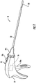
- an endoscopic surgical system which may be in the form of an endoscopic surgical stapler, is designated surgical stapler 10.
- the surgical stapler 10 may be utilized in any suitable surgical procedure, such as the resection of tissue in the lung, intestines or other organs, involving the use of brachytherapy.
- the surgical stapler 10, and/or components thereof, may also be utilized to attach suture, mesh, or other flexible material to tissue.
- the surgical stapler 10 includes a handle assembly 20 and an elongated body portion 30 that extends distally from the handle assembly 20 along a longitudinal axis "L.”
- the elongated body portion 30 supports an end effector 100 at a distal end of the elongated body portion 30.
- the end effector 100 is selectively detachable/attachable from/to the elongated body portion 30 and may be rotatable and/or articulatable relative to the elongated body portion 30.
- the elongated body portion 30 may be rotatable relative to the handle assembly 20.
- the distal end of the elongated body portion 30 may include a quick connector that is controllable via the handle assembly 20 to enable quick connection and/or release of the end effector 100 to/from the elongated body portion 30, for example, to provide a safe operating distance from any radiation source emanating from the fasteners (e.g., radioactive source 146 seen in FIG. 7 ) described herein.
- a quick connector that is controllable via the handle assembly 20 to enable quick connection and/or release of the end effector 100 to/from the elongated body portion 30, for example, to provide a safe operating distance from any radiation source emanating from the fasteners (e.g., radioactive source 146 seen in FIG. 7 ) described herein.
- the handle assembly 20 of the surgical stapler 10 includes a handle housing 22 and one or more actuators 24a, 24b, 24c coupled to the handle housing 22 to enable the end effector 100 to perform one or more functions (e.g., rotation, articulation, firing, etc.).
- the actuator 24a of the handle assembly 20 is operatively coupled to a drive assembly 26 supported within the handle assembly 20 to fire the end effector 100 of the surgical stapler 10 upon an actuation of the actuator 24a of the handle assembly 20 as described in greater detail below.
- the handle assembly 20 may include a directional clutch that prevents the actuator 24a of the handle assembly 20 from retracting until fully squeezed or actuated.
- a manually actuated handle assembly is shown, the handle could be motorized or the end effector can be configured as part of a component that connects to a robotic surgical system.
- the end effector 100 of the surgical stapler 10 includes a body 110 having a proximal end 110a and a distal end 110b.
- the body 110 of the end effector 100 further includes an inner surface 110c defining inner channels 110d that receive a firing assembly 130 of the end effector 100.
- the proximal end 110a of the body 110 is configured to selectively couple to a distal end of the elongated body portion 30 of the surgical stapler 10.
- the proximal end 110a of the body 110 may be contoured with orientation features, protrusions and/or hooks to provide quick and easy attachment to the distal end of the elongated body portion 30 of the surgical stapler 10.
- the proximal end 110a of the end effector 100 may include any suitable mechanical connection such as a snap-on type connection for coupling to the elongated body portion 30 of the surgical stapler 10.
- the body 110 of the end effector 100 is supported within an outer sleeve 120 of the end effector 100.
- the outer sleeve 120 of the end effector 100 includes a tab 122 that extends inwardly to couple the outer sleeve 120 within a notch 110e defined in an outer surface of the body 110 of the end effector 100.
- the outer sleeve 120 of the end effector 100 may have any suitable diameter such as, for example, 8 mm or smaller to enable passage through a standard 8mm trocar (not shown) or the like.
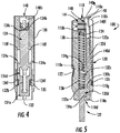
- the firing assembly 130 of the end effector 100 includes a firing bar 132 that is axially movable within the inner channel 110d of the body 110 of the end effector 100.
- the firing bar 132 of the firing assembly 130 extends proximally from the end effector 100 and is configured to operatively couple to the drive assembly 26 of the surgical stapler 10.
- the firing bar 132 extends distally to an abutment wall 132a of the firing bar 132 that connects to a cam fin 132b of the firing bar 132.
- the cam fin 132b of the firing bar 132 extends distally to drive wall 132c.
- a cam member 132d of the firing bar 132 is disposed adjacent to the drive wall 132c of the cam fin 132b and extends distally to a camming surface 132e at a distal end of the firing bar 132.
- the camming surface 132e of the firing bar 132 may be rounded.
- the firing assembly 130 of the end effector 100 further includes a pusher 134 coupled to the firing bar 132 of the firing assembly 130.
- the pusher 134 of the firing assembly 130 includes a proximal end 134a that is received in a recess 132d defined in the firing bar 132 of the firing assembly 130 adjacent to the cam fin 132b of the firing bar 132.
- the pusher 134 of the firing assembly 130 extends distally to a notch 134c in a distal end 134b of the pusher 134.
- the notch 134c of the pusher 134 may be W-shaped.
- the notch 134c may be formed by two U-shaped notches disposed in the same plane adjacent to one another that act as cam forming surfaces for fasteners 144 of the end effector 100 as described in greater detail below.
- the pusher 134 of the firing assembly 130 further defines an opening 134d that is configured to receive the cam fin 132b of the firing bar 132 therein.
- the pusher 134 is axially movable within the body 110 of the end effector 100 and selectively engagable with a pusher stop 110f formed in the body 110 distal to front shoulders 134e of the pusher 134.
- the pusher 134 further includes rear shoulders 134f that are selectively engagable with a retainer clip 135 having opposed arms 135a, 135b coupled by a bridge member 135c.
- the retainer clip 135 may have a U-shaped configuration.
- the retainer clip 135 of the end effector 100 is mounted within a clip notch 110g defined in an outer surface of the body 110 of the end effector 100 and is positioned to limit proximal movement of the pusher 134 of the firing assembly 130 upon contact between the rear shoulders 134f of the pusher 134 and the opposed arms 135a, 135b of the retainer clip 135.
- the pusher 134 also includes a spring tab 134g depending from a bottom surface of the pusher 134.
- the firing assembly 130 of the end effector 100 further includes first and second springs 136, 138 that bias the firing bar 132 of the firing assembly 130 and the pusher 134 of the firing assembly 130 proximally.
- the first spring 136 of the firing assembly 130 may, for example, provide predetermined cam release timing of an anvil 140 of the end effector 100, described in greater detail below.
- the second spring 138 of the firing assembly 130 may, for example, function to return the pusher 134 of the firing assembly 130 to a proximal or initial position.
- the proximal end of the first spring 136 is disposed in contact with the abutment surface 132a of the firing bar 132.
- the distal end of the first spring 136 contacts with a rear surface of the spring partition 134g of the pusher 134.
- the proximal end of the second spring 138 contacts a front surface of the spring partition 134g and the distal end of the second spring 138 extends distally into contact with a spring stop 110h defined in the body 110 of the end effector 100.
- a spring rate of the first spring 136 of the firing assembly 130 may be greater than a spring rate of the second spring 138 of the firing assembly 130, whereby the first spring 136 is stronger than the second spring 138.
- One or both of the first and second springs 136, 138 may be preloaded (e.g., maintained at least partially compressed within the body 110 of the end effector 100).
- the anvil 140 of the end effector 100 includes a base member 140a having support legs 140b, 140c.
- the anvil 140 which may be in the form of a leaf spring, further includes an elongated arm 140d that extends distally from the base member 140a of the anvil 140.
- the elongated arm 140d of the anvil 140 is connected to a head 140e of the anvil 140 via a transition portion 140f of the anvil 140 disposed at an angle relative to the elongated arm 140d and the head 140e.
- the head 140e of the anvil 140 includes a lip 140g depending from the head 140c.
- the lip 140g has a fastener forming surface 140h extending into a firing track 148 of the end effector 100 that is defined in registration with the pusher 134 of the firing assembly 130 and the lip 140g of the anvil 140 of the firing assembly 130.
- the firing assembly 130 of the end effector 100 further includes a U-shaped stock spring 142 that extends distally from the retainer clip 135 and is configured to urge the fasteners 144 of the end effector 100 toward the firing track 148 of the end effector 100.
- the stock spring 142 of the firing assembly 130 supports a stock of fasteners 144 (e.g., six staples) that are individually engagable by the W-shaped notch 134c defined in the distal end 134b of the pusher 134 of the firing assembly 130.
- the stock spring 142 engages a bottom or last fastener 144z of the stock of unfired fasteners 144 and urges the unfired stock of fasteners 144 into the firing track 148 of the end effector 100 adjacent to the notch 134c of the pusher 134, whereby the stock spring 142 of the end effector 100 functions to load successive unfired fasteners 144 into a firing position within the firing track 148 (e.g., one at a time so that the unfired fasteners 146 can be sequentially fired).
- each fastener 144 of the stock of fasteners 144 includes a backspan 144a that extends to opposite first and second ends 144b, 144c, which may be in the form of elbow segments.
- Each fastener 144 may have four or more sides "S1-S4" ( FIG. 10 ) while the fastener 144 is in an unformed state.
- each fastener 144 may have a W-shaped configuration.
- the backspan 144a of each fastener 144 may support a radioactive source or isotope 146 (e.g., an isotope capsule) thereon, for example, to effectuate a brachytherapy treatment.
- the radioactive source 146 of the fastener 144 may be positioned to surround the backspan 144a of the fastener 144 along a central portion of the backspan 144a.
- the radioactive source 146 of the backspan 144a can include any suitable radioactive isotope, or combinations thereof, such as yttrium-90, cobalt-60, molybdenum-99, lutetium-177, homium-166, iodine-125, iodine-131, palladium-103, samarium-153, phosphorus-32, boron-10, actinium-225, lead 212, etc..
- the first arm 144d of the fastener 144 may include the first end 144b of the backspan 144a and the second arm 144e of the fastener 144 may include the second end 144c of the backspan 144a.
- each of the first and second arms 144d, 144e of the fastener 144 may have an L-shaped configuration.
- Each of the first and second arms 144d, 144e includes a crossing segment 144f, an elbow segment 144g, and a tissue engaging segment 144h that extends to a sharpened tip 144i.
- Each tissue engaging segment 144h may be inwardly arced with a radius corresponding to a length of its respective crossing segment 144f.
- the crossing segments 144f of the respective first and second arms 144d, 144e extend from a respective one of the first and second ends 144b, 144c of the backspan 144a.
- the elbow segment 144g of the respective first and second arms 144d, 144e couples the crossing segments 144f of the respective first and second arms 144d, 144e to the tissue engaging segments 144h of the respective first and second arms 144d, 144e.
- the tissue engaging segment 144h of the first arm 144d extends in the first direction and the tissue engaging segment 144h of the second arm 144e extends in the second direction such that the tissue engaging segments 144h of the respective first and second arms 144d, 144e extend in opposite directions.
- the firing bar 132 of the firing assembly 130 is advanced distally along the longitudinal axis "L" of the elongated body portion 30 of the surgical stapler 10, for example, upon an actuation of actuator 24a (e.g., a trigger) of the handle assembly 20 of the surgical stapler 10 relative to the handle housing 22 of the surgical stapler 10.
- actuator 24a e.g., a trigger
- the abutment wall 132a of the firing bar 132 compresses the first spring 136 of the firing assembly 130 against the spring partition 134g of the pusher 134 of the firing assembly 130.
- the spring partition 134g of the pusher 134 transmits a driving force to the second spring 138 to compress the second spring 138.
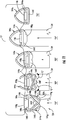
- the pusher 134 of the firing assembly 130 advances distally forward so that the pusher 134 drives an innermost fastener 144x of the stack of fasteners 144 distally to a first forming position ( FIG. 8B and designation "F1" seen in FIGS. 10 and 11 ) in the firing track 148.
- the backspan 144a of the fastener 144x, or portions thereof engage the fastener formation surface 140h of the lip 140g of the anvil 140 so that the fastener 144x can begin to form.
- a width of the lip 140g of the anvil 140 is narrower than a width of the backspan 144a of the fastener 144x such that the lip 140g stops the backspan 144a of the fastener 144x from advancing distally while the first and second arms 144d, 144e of the fastener 144x are advanced alongside the lip 140g of the anvil 140.
- the elbow segments 144g of the respective first and second arms 144d, 144e are received in the notch 134c of the pusher 134 adjacent a center of the notch 134c. Further distal movement of the pusher 134 of the firing assembly 130 toward the lip 1406 of the anvil 140 of the firing assembly 130 drives the elbow segments 144g of the respective first and second arms 144d, 144e against the notch 134c of the pusher 134 and radially away from one another, as illustrated by arrows "C" (see designation "F2" in FIG. 11 ) without bending the elbow segments 144g of the respective first and second arms 144d, 144e.
- first and second arms 144d, 144e of the fastener 144x pivot about the respective ends 144b, 144c of the backspan 144a of the fastener 144x in simultaneous circular or radial movement, whereby the ends 144b, 144c of the backspan 144a bend inwardly in a convergent manner.
- Such simultaneous circular movement of the first and second arms 144d, 144e causes the tissue engaging segments 144h of the respective first and second arms 144d, 144e to approximate one another/converge so that the sharpened tips 144i thereof penetrate and grip tissue "T" disposed adjacent to the fastener 144x.
- the connector segments 144x of the respective first and second arms 144d, 144e of the fastener 144x also converge toward the backspan 144a of the fastener 144x until the backspan 144a and the connector segments 144x of the respective first and second arms 144d, 144e are parallel, or substantially parallel, to one another (see designation "F3" in FIG. 11 ) so that the fastener 144x is fully formed, or substantially fully formed.
- the first spring 136 of the firing assembly 130 may have a higher spring constant than the second spring 138 of the firing assembly 130 to provide sufficient cam timing by enabling the fastener 144x of the firing assembly 130 to fully form before the anvil 140 of the firing assembly 130 can separate from the fastener 144x upon engagement with the camming surface 132e of the firing bar 132 of the firing assembly 130.
- the number of sides of the fastener 144x may reduce to three sides.
- the tissue engaging segment 144h of the first arm 144d may define a first formed side "FS1”
- the tissue engaging segment 144h of the second arm 144e may define a second formed side "FS2”
- the connecting segments 144f of the first and second arms 144d, 144e may collectively define a third formed side "FS3.”
- the fastener 144x, in the fully formed configuration may have a D-shaped configuration.
- the three formed sides "FS1-FS3" of the fastener 144x may surround the backspan 144a and/or the radioactive source 146 supported on the backspan 144a such that the backspan 144a and/or the radioactive source 146 is supported between the three formed sides "FS1-FS3" of the fastener 144x.
- the radioactive source 146 and/or the backspan 144a may be spaced from the connecting segments 144f of the fastener 144x in both the unformed and formed configurations to limit the risk of damage to the radioactive source 146 during a firing.
- the camming surface 132e of the cam member 132d of the firing bar 132 wedges between the pusher 134 and the anvil 140 of the firing assembly 130 to engage the transition portion 140f of the anvil 140 and pivot the anvil 140 about a proximal pivot point "P," as illustrated by arrow "B" (see FIG. 8D ).
- the lip 140g of the head 140c of the anvil 140 separates from the fastener 144x so that the fastener forming surface 140h of the anvil 140 separates from the backspan 144a of the formed fastener 144x.
- the pusher 134 of the firing assembly 130 continues to distally drive the formed fastener 144x past the lip 140g of the anvil 140 (see designation "F4" in FIG. 11 ) so that the formed fastener 144x is dispensed from the end effector 100 (see designation "F5" in FIG. 11 ).
- the formed fastener 144x is advanced through a distal opening or fastener exit 150 (see FIG. 2 ) defined in the body 110 of the end effector 100 and secured to the tissue "T" with the backspan 144a of the formed fastener 144x and/or the radioactive source 146 of the backspan 144a disposed in contacting relation with the tissue "T” (e.g., diseased tissue) to treat the tissue "T.”
- tissue "T" e.g., diseased tissue
- the first and second springs 136, 138 of the firing assembly 130 bias the pusher 134 and the firing bar 132 of the firing assembly 130 proximal toward their pre-fired or initial positions.
- the anvil 140 of the firing assembly 130 biases back to its initial position and the stock spring 142 pushes the remaining unfired fasteners 140 toward the firing track 148 and into registration with the pusher 134 of the firing assembly 130.
- the end effector 100 of the surgical stapler 10 can then be re-fired and the process repeated as desired until all fasteners 144 are fired.
- the end effector 100 can be disposable. In certain embodiments, the end effector 100 is reusable and/or autoclavable. In some embodiments, the sleeve 120 may be removed or adjusted by manipulating the tab 122 thereof to enable additional fasteners 144 to be loaded into the end effector 100 for reuse of the end effector 100.
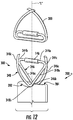
- FIG. 12 one embodiment of a pusher, shown generally as pusher 200, may be utilized with end effector 100 to secure to thicker tissue "T."
- the pusher 200 of the end effector 100 includes first and second notches 202, 204 formed in a distal end thereof.
- the first and second notches 202, 204 may have U-shaped configurations.
- the first and second notches 202, 204 of the pusher 200 are supported in different planes that are parallel to one another to enable increased fastener height.
- the first and second notches 202, 204 of the pusher 200 are also laterally offset from the longitudinal axis "L" in opposite directions of one another.
- the pusher 200 of the end effector 100 is configured to receive another embodiment of a fastener 300 of the end effector 100.
- the fastener 300 of the end effector 100 includes a backspan 344a that extends to opposite first and second ends 344b, 344c.
- the backspan 344a supports a radioactive source 146 such as an isotope capsule thereon.
- the first end 344b of the backspan 344a supports a first arm 346 and the second end 344c of the backspan 344a supports a second arm 348.
- the first and second arms 346, 348 may have an L-shaped configuration.
- the first arm 346 of the backspan 344a includes a crossing segment 346a, an elbow segment 346b extending from the crossing segment 346a, and a tissue engaging segment 346c extending from the elbow segment 346b.
- the second arm 348 includes a crossing segment 348a, an elbow segment 348b extending from the crossing segment 348a, and a tissue engaging segment 348c extending from the elbow segment 348b.
- One or both of the first and second arms 346, 348 of the fastener 300 may be longer than the first and second arms of the fastener 144 in order to accommodate larger tissue thickness and/or an increased volume of radioactive source 146.
- one or more of the crossing, elbow, and tissue engaging segments 346a, 346b, 346c of the first arm 346 may be longer than the corresponding crossing, elbow, and tissue engaging segments 348a, 348b, 348c of the second arm 348, or vice-versa.
- the end effector 100 can be a disposable cartridge or may be reusable/autoclavable and may be selectively removable or reattachable to the surgical stapler 10.
- any of the presently disclosed fasteners, end effectors, and/or surgical staplers may be shipped and/or stored in one or more isolated/protected container (not shown) configured to protect against radiation emanating from the radioactive source.
- securement of any of the components of the presently disclosed devices can be effectuated using known fastening techniques such welding, crimping, gluing, fastening, etc.
- the various embodiments disclosed herein may also be configured to work with robotic surgical systems and what is commonly referred to as "Telesurgery.”
- Such systems employ various robotic elements to assist the clinician and allow remote operation (or partial remote operation) of surgical instrumentation.
- Various robotic arms, gears, cams, pulleys, electric and mechanical motors, etc. may be employed for this purpose and may be designed with a robotic surgical system to assist the clinician during the course of an operation or treatment.
- Such robotic systems may include remotely steerable systems, automatically flexible surgical systems, remotely flexible surgical systems, remotely articulating surgical systems, wireless surgical systems, modular or selectively configurable remotely operated surgical systems, etc.
- the robotic surgical systems may be employed with one or more consoles that are next to the operating theater or located in a remote location.
- one team of clinicians may prep the patient for surgery and configure the robotic surgical system with one or more of the instruments disclosed herein while another clinician (or group of clinicians) remotely control the instruments via the robotic surgical system.
- another clinician or group of clinicians
- a highly skilled clinician may perform multiple operations in multiple locations without leaving his/her remote console which can be both economically advantageous and a benefit to the patient or a series of patients.
- the robotic arms of the surgical system are typically coupled to a pair of master handles by a controller.
- the handles can be moved by the clinician to produce a corresponding movement of the working ends of any type of surgical instrument (e.g., end effectors, graspers, knifes, scissors, etc.) which may complement the use of one or more of the embodiments described herein.
- the movement of the master handles may be scaled so that the working ends have a corresponding movement that is different, smaller or larger, than the movement performed by the operating hands of the clinician.
- the scale factor or gearing ratio may be adjustable so that the operator can control the resolution of the working ends of the surgical instrument(s).
- the master handles may include various sensors to provide feedback to the clinician relating to various tissue parameters or conditions, e.g., tissue resistance due to manipulation, cutting or otherwise treating, pressure by the instrument onto the tissue, tissue temperature, tissue impedance, etc. As can be appreciated, such sensors provide the clinician with enhanced tactile feedback simulating actual operating conditions.
- the master handles may also include a variety of different actuators for delicate tissue manipulation or treatment further enhancing the clinician's ability to mimic actual operating conditions.
- a medical work station is shown generally as work station 1000 and generally may include a plurality of robot arms 1002, 1003; a control device 1004; and an operating console 1005 coupled with the control device 1004.
- the operating console 1005 may include a display device 1006, which may be set up in particular to display three-dimensional images; and manual input devices 1007, 1008, by means of which a person (not shown), for example a clinician, may be able to telemanipulate the robot arms 1002, 1003 in a first operating mode.
- Each of the robot arms 1002, 1003 may include a plurality of members, which are connected through joints, and an attaching device 1009, 1011, to which may be attached, for example, a surgical tool "ST" supporting an end effector 1100 (e.g., a pair of jaw members) in accordance with any one of several embodiments disclosed herein, as will be described in greater detail below.
- an attaching device 1009, 1011 to which may be attached, for example, a surgical tool "ST" supporting an end effector 1100 (e.g., a pair of jaw members) in accordance with any one of several embodiments disclosed herein, as will be described in greater detail below.
- the robot arms 1002, 1003 may be driven by electric drives (not shown) that are connected to the control device 1004.
- the control device 1004 e.g., a computer
- the control device 1004 may be set up to activate the drives, in particular by means of a computer program, in such a way that the robot arms 1002, 1003, their attaching devices 1009, 1011 and thus the surgical tool (including the end effector 1100) execute a desired movement according to a movement defined by means of the manual input devices 1007, 1008.
- the control device 1004 may also be set up in such a way that it regulates the movement of the robot arms 1002, 1003 and/or of the drives.
- the medical work station 1000 may be configured for use on a patient "P" lying on a patient table 1012 to be treated in a minimally invasive manner by means of the end effector 1100.
- the medical work station 1000 may also include more than two robot arms 1002, 1003, the additional robot arms likewise connected to the control device 1004 and telemanipulatable by means of the operating console 1005.
- a surgical system such as the presently disclosed surgical system, may also be attached to the additional robot arm.
- the medical work station 1000 may include a database 1014 coupled with the control device 1004. In some embodiments, preoperative data from patient/living being "P" and/or anatomical atlases may be stored in the database 1014.
Landscapes
- Health & Medical Sciences (AREA)
- Engineering & Computer Science (AREA)
- Life Sciences & Earth Sciences (AREA)
- Biomedical Technology (AREA)
- Surgery (AREA)
- Nuclear Medicine, Radiotherapy & Molecular Imaging (AREA)
- Animal Behavior & Ethology (AREA)
- General Health & Medical Sciences (AREA)
- Public Health (AREA)
- Veterinary Medicine (AREA)
- Heart & Thoracic Surgery (AREA)
- Medical Informatics (AREA)
- Molecular Biology (AREA)
- Radiology & Medical Imaging (AREA)
- Pathology (AREA)
- Robotics (AREA)
- Surgical Instruments (AREA)
Claims (15)
- Effecteur terminal (100) pour un dispositif d'attache chirurgical (10), l'effecteur terminal comprenant :un corps (110) définissant un axe longitudinal (« L ») ;au moins une attache (144) ayant une configuration non formée et une configuration formée, l'au moins une attache comportant des premier et second bras (144d, 144e), les premier et second bras s'étendant dans des directions opposées, le premier bras ayant des premier et second segments coudés (144b, 144g), le premier segment coudé étant conçu pour se plier lorsque l'au moins une attache est formée, le second segment coudé étant conçu pour rester déplié lorsque l'au moins une attache est formée, l'au moins une attache comportant en outre une portée arrière (144a) qui s'étend entre les premier et second bras ;une enclume (140) accouplée de manière pivotante au corps et mobile entre une première position et une seconde position, l'enclume étant conçue pour venir en prise avec l'au moins une attache lorsqu'elle est dans la première position et pour se désaccoupler de l'au moins une attache lorsqu'elle est dans la seconde position ;un poussoir (134) conçu pour faire avancer l'au moins une attache distalement à travers le corps et pour qu'elle entre en prise avec l'enclume de façon à former l'au moins une attache contre l'enclume ;l'attache ayant plus de trois côtés lorsque les premier et second bras sont dans la configuration non formée, et seulement trois côtés lorsque les premier et second bras sont dans la configuration formée, chacun des premier et second bras comportant un segment d'intersection (144f) et un segment d'entrée en prise avec le tissu (144h), les segments d'intersection des premier et second bras convergeant vers la portée arrière et les segments d'entrée en prise avec le tissu des premier et second bras convergeant l'un vers l'autre, lorsque les premier et second bras sont déplacés de la configuration non formée à la configuration formée.
- Effecteur terminal (100) selon la revendication 1, dans lequel l'enclume (140) peut venir en prise avec la portée arrière (144a) de façon à former les premier et second bras (144d, 144e) autour de la portée arrière.
- Effecteur terminal (100) selon la revendication 2, dans lequel l'enclume (140) comporte une lèvre (140g), la lèvre définissant une surface de formation d'attache (140h) conçue pour entrer en contact avec la portée arrière (144a) de sorte que les premier et second bras (144d, 144e) peuvent pivoter autour de l'enclume pour former l'au moins une attache (144).
- Effecteur terminal (100) selon une quelconque revendication précédente, dans lequel la portée arrière (144a) supporte une source radioactive (146).
- Effecteur terminal (100) selon la revendication 4, dans lequel la source radioactive (146) est supportée entre les trois côtés de l'attache (144) lorsque les premier et second bras (144d, 144e) sont dans la configuration formée.
- Effecteur terminal (100) selon la revendication 4 ou la revendication 5, dans lequel la source radioactive se présente sous la forme d'une capsule isotopique entourant la portée arrière (144a).
- Effecteur terminal (100) selon une quelconque revendication précédente, dans lequel les segments d'intersection (144f) sont reliés aux segments d'entrée en prise avec le tissu (144h) des premier et second bras (144d, 144e) respectifs par les seconds segments coudés (144g).
- Effecteur terminal (100) selon une quelconque revendication précédente, dans lequel la portée arrière (144a), le premier bras (144d), le second bras (144e), ou des combinaisons de ceux-ci, comportent un fil de titane.
- Effecteur terminal (100) selon une quelconque revendication précédente, comportant en outre une came de libération d'enclume (132d) qui peut venir en prise sélectivement avec l'enclume (140) pour désaccoupler l'enclume de l'au moins une attache (144) après la formation de l'au moins une attache.
- Effecteur terminal (100) selon une quelconque revendication précédente, dans lequel le poussoir (134) comporte une encoche (134c) formée dans une extrémité distale de celui-ci, l'encoche étant conçue pour recevoir l'au moins une attache (144).
- Effecteur terminal (100) selon une quelconque revendication précédente, comprenant en outre une barre de déclenchement (132), la barre de déclenchement pouvant être translatée axialement pour translater axialement le poussoir (134).
- Effecteur terminal (100) selon la revendication 11, dans lequel la barre de déclenchement (132) et le poussoir (134) sont sollicités par ressort par au moins un ressort.
- Effecteur terminal (100) selon la revendication 12, dans lequel l'au moins un ressort comporte un premier ressort (136) et un second ressort (138), le premier ressort présentant une raideur différente de celle du second ressort.
- Dispositif d'attache chirurgical (10), comprenant :un ensemble poignée (20) ;une partie de corps allongée (30) s'étendant distalement à partir de l'ensemble poignée et définissant un axe longitudinal ; etl'effecteur terminal (100) selon l'une quelconque des revendications 2 à 13, l'effecteur terminal étant supporté sur une extrémité distale de la partie de corps allongée.
- Dispositif d'attache chirurgical (10) selon la revendication 14, dans lequel l'au moins une attache (144) comporte une pluralité d'attaches empilées qui sont positionnées pour un déclenchement séquentiel.
Applications Claiming Priority (1)
| Application Number | Priority Date | Filing Date | Title |
|---|---|---|---|
| US15/181,767 US10251645B2 (en) | 2016-06-14 | 2016-06-14 | Surgical fastening with W-shaped surgical fasteners |
Publications (3)
| Publication Number | Publication Date |
|---|---|
| EP3257448A2 EP3257448A2 (fr) | 2017-12-20 |
| EP3257448A3 EP3257448A3 (fr) | 2018-03-14 |
| EP3257448B1 true EP3257448B1 (fr) | 2021-03-10 |
Family
ID=59054032
Family Applications (1)
| Application Number | Title | Priority Date | Filing Date |
|---|---|---|---|
| EP17175562.2A Not-in-force EP3257448B1 (fr) | 2016-06-14 | 2017-06-12 | Fixation chirurgicale avec attaches chirurgicales en forme de w |
Country Status (6)
| Country | Link |
|---|---|
| US (1) | US10251645B2 (fr) |
| EP (1) | EP3257448B1 (fr) |
| JP (1) | JP6979801B2 (fr) |
| CN (1) | CN107497058A (fr) |
| AU (1) | AU2017203335A1 (fr) |
| CA (1) | CA2970115A1 (fr) |
Families Citing this family (175)
| Publication number | Priority date | Publication date | Assignee | Title |
|---|---|---|---|---|
| US20070084897A1 (en) | 2003-05-20 | 2007-04-19 | Shelton Frederick E Iv | Articulating surgical stapling instrument incorporating a two-piece e-beam firing mechanism |
| US9060770B2 (en) | 2003-05-20 | 2015-06-23 | Ethicon Endo-Surgery, Inc. | Robotically-driven surgical instrument with E-beam driver |
| US9072535B2 (en) | 2011-05-27 | 2015-07-07 | Ethicon Endo-Surgery, Inc. | Surgical stapling instruments with rotatable staple deployment arrangements |
| US11890012B2 (en) | 2004-07-28 | 2024-02-06 | Cilag Gmbh International | Staple cartridge comprising cartridge body and attached support |
| US11998198B2 (en) | 2004-07-28 | 2024-06-04 | Cilag Gmbh International | Surgical stapling instrument incorporating a two-piece E-beam firing mechanism |
| US11246590B2 (en) | 2005-08-31 | 2022-02-15 | Cilag Gmbh International | Staple cartridge including staple drivers having different unfired heights |
| US10159482B2 (en) | 2005-08-31 | 2018-12-25 | Ethicon Llc | Fastener cartridge assembly comprising a fixed anvil and different staple heights |
| US7669746B2 (en) | 2005-08-31 | 2010-03-02 | Ethicon Endo-Surgery, Inc. | Staple cartridges for forming staples having differing formed staple heights |
| US7845537B2 (en) | 2006-01-31 | 2010-12-07 | Ethicon Endo-Surgery, Inc. | Surgical instrument having recording capabilities |
| US8708213B2 (en) | 2006-01-31 | 2014-04-29 | Ethicon Endo-Surgery, Inc. | Surgical instrument having a feedback system |
| US8186555B2 (en) | 2006-01-31 | 2012-05-29 | Ethicon Endo-Surgery, Inc. | Motor-driven surgical cutting and fastening instrument with mechanical closure system |
| US11793518B2 (en) | 2006-01-31 | 2023-10-24 | Cilag Gmbh International | Powered surgical instruments with firing system lockout arrangements |
| US20120292367A1 (en) | 2006-01-31 | 2012-11-22 | Ethicon Endo-Surgery, Inc. | Robotically-controlled end effector |
| US8992422B2 (en) | 2006-03-23 | 2015-03-31 | Ethicon Endo-Surgery, Inc. | Robotically-controlled endoscopic accessory channel |
| US11980366B2 (en) | 2006-10-03 | 2024-05-14 | Cilag Gmbh International | Surgical instrument |
| US8632535B2 (en) | 2007-01-10 | 2014-01-21 | Ethicon Endo-Surgery, Inc. | Interlock and surgical instrument including same |
| US8684253B2 (en) | 2007-01-10 | 2014-04-01 | Ethicon Endo-Surgery, Inc. | Surgical instrument with wireless communication between a control unit of a robotic system and remote sensor |
| US20080169332A1 (en) | 2007-01-11 | 2008-07-17 | Shelton Frederick E | Surgical stapling device with a curved cutting member |
| US11857181B2 (en) | 2007-06-04 | 2024-01-02 | Cilag Gmbh International | Robotically-controlled shaft based rotary drive systems for surgical instruments |
| US8931682B2 (en) | 2007-06-04 | 2015-01-13 | Ethicon Endo-Surgery, Inc. | Robotically-controlled shaft based rotary drive systems for surgical instruments |
| US11849941B2 (en) | 2007-06-29 | 2023-12-26 | Cilag Gmbh International | Staple cartridge having staple cavities extending at a transverse angle relative to a longitudinal cartridge axis |
| RU2493788C2 (ru) | 2008-02-14 | 2013-09-27 | Этикон Эндо-Серджери, Инк. | Хирургический режущий и крепежный инструмент, имеющий радиочастотные электроды |
| US8573465B2 (en) | 2008-02-14 | 2013-11-05 | Ethicon Endo-Surgery, Inc. | Robotically-controlled surgical end effector system with rotary actuated closure systems |
| US8636736B2 (en) | 2008-02-14 | 2014-01-28 | Ethicon Endo-Surgery, Inc. | Motorized surgical cutting and fastening instrument |
| US11986183B2 (en) | 2008-02-14 | 2024-05-21 | Cilag Gmbh International | Surgical cutting and fastening instrument comprising a plurality of sensors to measure an electrical parameter |
| US20130153641A1 (en) | 2008-02-15 | 2013-06-20 | Ethicon Endo-Surgery, Inc. | Releasable layer of material and surgical end effector having the same |
| US9386983B2 (en) | 2008-09-23 | 2016-07-12 | Ethicon Endo-Surgery, Llc | Robotically-controlled motorized surgical instrument |
| US8210411B2 (en) | 2008-09-23 | 2012-07-03 | Ethicon Endo-Surgery, Inc. | Motor-driven surgical cutting instrument |
| US9005230B2 (en) | 2008-09-23 | 2015-04-14 | Ethicon Endo-Surgery, Inc. | Motorized surgical instrument |
| US8608045B2 (en) | 2008-10-10 | 2013-12-17 | Ethicon Endo-Sugery, Inc. | Powered surgical cutting and stapling apparatus with manually retractable firing system |
| US11812965B2 (en) | 2010-09-30 | 2023-11-14 | Cilag Gmbh International | Layer of material for a surgical end effector |
| US11925354B2 (en) | 2010-09-30 | 2024-03-12 | Cilag Gmbh International | Staple cartridge comprising staples positioned within a compressible portion thereof |
| US9629814B2 (en) | 2010-09-30 | 2017-04-25 | Ethicon Endo-Surgery, Llc | Tissue thickness compensator configured to redistribute compressive forces |
| US10945731B2 (en) | 2010-09-30 | 2021-03-16 | Ethicon Llc | Tissue thickness compensator comprising controlled release and expansion |
| US12213666B2 (en) | 2010-09-30 | 2025-02-04 | Cilag Gmbh International | Tissue thickness compensator comprising layers |
| US9320523B2 (en) | 2012-03-28 | 2016-04-26 | Ethicon Endo-Surgery, Llc | Tissue thickness compensator comprising tissue ingrowth features |
| US10405854B2 (en) | 2010-09-30 | 2019-09-10 | Ethicon Llc | Surgical stapling cartridge with layer retention features |
| US8695866B2 (en) | 2010-10-01 | 2014-04-15 | Ethicon Endo-Surgery, Inc. | Surgical instrument having a power control circuit |
| BR112013027794B1 (pt) | 2011-04-29 | 2020-12-15 | Ethicon Endo-Surgery, Inc | Conjunto de cartucho de grampos |
| US11207064B2 (en) | 2011-05-27 | 2021-12-28 | Cilag Gmbh International | Automated end effector component reloading system for use with a robotic system |
| MX358135B (es) | 2012-03-28 | 2018-08-06 | Ethicon Endo Surgery Inc | Compensador de grosor de tejido que comprende una pluralidad de capas. |
| MX350846B (es) | 2012-03-28 | 2017-09-22 | Ethicon Endo Surgery Inc | Compensador de grosor de tejido que comprende cápsulas que definen un ambiente de baja presión. |
| US9101358B2 (en) | 2012-06-15 | 2015-08-11 | Ethicon Endo-Surgery, Inc. | Articulatable surgical instrument comprising a firing drive |
| US20140001231A1 (en) | 2012-06-28 | 2014-01-02 | Ethicon Endo-Surgery, Inc. | Firing system lockout arrangements for surgical instruments |
| US12383267B2 (en) | 2012-06-28 | 2025-08-12 | Cilag Gmbh International | Robotically powered surgical device with manually-actuatable reversing system |
| US9289256B2 (en) | 2012-06-28 | 2016-03-22 | Ethicon Endo-Surgery, Llc | Surgical end effectors having angled tissue-contacting surfaces |
| MX368026B (es) | 2013-03-01 | 2019-09-12 | Ethicon Endo Surgery Inc | Instrumento quirúrgico articulable con vías conductoras para la comunicación de la señal. |
| RU2669463C2 (ru) | 2013-03-01 | 2018-10-11 | Этикон Эндо-Серджери, Инк. | Хирургический инструмент с мягким упором |
| US9629629B2 (en) | 2013-03-14 | 2017-04-25 | Ethicon Endo-Surgey, LLC | Control systems for surgical instruments |
| BR112015026109B1 (pt) | 2013-04-16 | 2022-02-22 | Ethicon Endo-Surgery, Inc | Instrumento cirúrgico |
| US20150053737A1 (en) | 2013-08-23 | 2015-02-26 | Ethicon Endo-Surgery, Inc. | End effector detection systems for surgical instruments |
| US12232723B2 (en) | 2014-03-26 | 2025-02-25 | Cilag Gmbh International | Systems and methods for controlling a segmented circuit |
| US10013049B2 (en) | 2014-03-26 | 2018-07-03 | Ethicon Llc | Power management through sleep options of segmented circuit and wake up control |
| US9750499B2 (en) | 2014-03-26 | 2017-09-05 | Ethicon Llc | Surgical stapling instrument system |
| CN106456158B (zh) | 2014-04-16 | 2019-02-05 | 伊西康内外科有限责任公司 | 包括非一致紧固件的紧固件仓 |
| US10327764B2 (en) | 2014-09-26 | 2019-06-25 | Ethicon Llc | Method for creating a flexible staple line |
| CN106456176B (zh) | 2014-04-16 | 2019-06-28 | 伊西康内外科有限责任公司 | 包括具有不同构型的延伸部的紧固件仓 |
| US20150297223A1 (en) | 2014-04-16 | 2015-10-22 | Ethicon Endo-Surgery, Inc. | Fastener cartridges including extensions having different configurations |
| JP6532889B2 (ja) | 2014-04-16 | 2019-06-19 | エシコン エルエルシーEthicon LLC | 締結具カートリッジ組立体及びステープル保持具カバー配置構成 |
| BR112017004361B1 (pt) | 2014-09-05 | 2023-04-11 | Ethicon Llc | Sistema eletrônico para um instrumento cirúrgico |
| US11311294B2 (en) | 2014-09-05 | 2022-04-26 | Cilag Gmbh International | Powered medical device including measurement of closure state of jaws |
| US10105142B2 (en) | 2014-09-18 | 2018-10-23 | Ethicon Llc | Surgical stapler with plurality of cutting elements |
| US11523821B2 (en) | 2014-09-26 | 2022-12-13 | Cilag Gmbh International | Method for creating a flexible staple line |
| US9924944B2 (en) | 2014-10-16 | 2018-03-27 | Ethicon Llc | Staple cartridge comprising an adjunct material |
| US10517594B2 (en) | 2014-10-29 | 2019-12-31 | Ethicon Llc | Cartridge assemblies for surgical staplers |
| US10736636B2 (en) | 2014-12-10 | 2020-08-11 | Ethicon Llc | Articulatable surgical instrument system |
| US10085748B2 (en) | 2014-12-18 | 2018-10-02 | Ethicon Llc | Locking arrangements for detachable shaft assemblies with articulatable surgical end effectors |
| US9987000B2 (en) | 2014-12-18 | 2018-06-05 | Ethicon Llc | Surgical instrument assembly comprising a flexible articulation system |
| US11154301B2 (en) | 2015-02-27 | 2021-10-26 | Cilag Gmbh International | Modular stapling assembly |
| US10441279B2 (en) | 2015-03-06 | 2019-10-15 | Ethicon Llc | Multiple level thresholds to modify operation of powered surgical instruments |
| US9808246B2 (en) | 2015-03-06 | 2017-11-07 | Ethicon Endo-Surgery, Llc | Method of operating a powered surgical instrument |
| US10390825B2 (en) | 2015-03-31 | 2019-08-27 | Ethicon Llc | Surgical instrument with progressive rotary drive systems |
| US10105139B2 (en) | 2015-09-23 | 2018-10-23 | Ethicon Llc | Surgical stapler having downstream current-based motor control |
| US10299878B2 (en) | 2015-09-25 | 2019-05-28 | Ethicon Llc | Implantable adjunct systems for determining adjunct skew |
| US11890015B2 (en) | 2015-09-30 | 2024-02-06 | Cilag Gmbh International | Compressible adjunct with crossing spacer fibers |
| US10172620B2 (en) | 2015-09-30 | 2019-01-08 | Ethicon Llc | Compressible adjuncts with bonding nodes |
| US10736633B2 (en) | 2015-09-30 | 2020-08-11 | Ethicon Llc | Compressible adjunct with looping members |
| US10292704B2 (en) | 2015-12-30 | 2019-05-21 | Ethicon Llc | Mechanisms for compensating for battery pack failure in powered surgical instruments |
| US10265068B2 (en) | 2015-12-30 | 2019-04-23 | Ethicon Llc | Surgical instruments with separable motors and motor control circuits |
| US11213293B2 (en) | 2016-02-09 | 2022-01-04 | Cilag Gmbh International | Articulatable surgical instruments with single articulation link arrangements |
| US10448948B2 (en) | 2016-02-12 | 2019-10-22 | Ethicon Llc | Mechanisms for compensating for drivetrain failure in powered surgical instruments |
| US10828028B2 (en) | 2016-04-15 | 2020-11-10 | Ethicon Llc | Surgical instrument with multiple program responses during a firing motion |
| US10357247B2 (en) | 2016-04-15 | 2019-07-23 | Ethicon Llc | Surgical instrument with multiple program responses during a firing motion |
| US20170296173A1 (en) | 2016-04-18 | 2017-10-19 | Ethicon Endo-Surgery, Llc | Method for operating a surgical instrument |
| US10500000B2 (en) | 2016-08-16 | 2019-12-10 | Ethicon Llc | Surgical tool with manual control of end effector jaws |
| US11090048B2 (en) | 2016-12-21 | 2021-08-17 | Cilag Gmbh International | Method for resetting a fuse of a surgical instrument shaft |
| JP7010956B2 (ja) | 2016-12-21 | 2022-01-26 | エシコン エルエルシー | 組織をステープル留めする方法 |
| US10758230B2 (en) | 2016-12-21 | 2020-09-01 | Ethicon Llc | Surgical instrument with primary and safety processors |
| US10639035B2 (en) | 2016-12-21 | 2020-05-05 | Ethicon Llc | Surgical stapling instruments and replaceable tool assemblies thereof |
| US10568626B2 (en) | 2016-12-21 | 2020-02-25 | Ethicon Llc | Surgical instruments with jaw opening features for increasing a jaw opening distance |
| JP7010957B2 (ja) | 2016-12-21 | 2022-01-26 | エシコン エルエルシー | ロックアウトを備えるシャフトアセンブリ |
| US10709901B2 (en) * | 2017-01-05 | 2020-07-14 | Covidien Lp | Implantable fasteners, applicators, and methods for brachytherapy |
| US10524784B2 (en) | 2017-05-05 | 2020-01-07 | Covidien Lp | Surgical staples with expandable backspan |
| US10779820B2 (en) | 2017-06-20 | 2020-09-22 | Ethicon Llc | Systems and methods for controlling motor speed according to user input for a surgical instrument |
| US10307170B2 (en) | 2017-06-20 | 2019-06-04 | Ethicon Llc | Method for closed loop control of motor velocity of a surgical stapling and cutting instrument |
| US11000279B2 (en) | 2017-06-28 | 2021-05-11 | Ethicon Llc | Surgical instrument comprising an articulation system ratio |
| EP4070740B1 (fr) | 2017-06-28 | 2025-03-26 | Cilag GmbH International | Instrument chirurgical comprenant des coupleurs rotatifs actionnables de façon sélective |
| USD906355S1 (en) | 2017-06-28 | 2020-12-29 | Ethicon Llc | Display screen or portion thereof with a graphical user interface for a surgical instrument |
| US10765427B2 (en) | 2017-06-28 | 2020-09-08 | Ethicon Llc | Method for articulating a surgical instrument |
| US10932772B2 (en) | 2017-06-29 | 2021-03-02 | Ethicon Llc | Methods for closed loop velocity control for robotic surgical instrument |
| US11944300B2 (en) | 2017-08-03 | 2024-04-02 | Cilag Gmbh International | Method for operating a surgical system bailout |
| US11974742B2 (en) | 2017-08-03 | 2024-05-07 | Cilag Gmbh International | Surgical system comprising an articulation bailout |
| US11134944B2 (en) | 2017-10-30 | 2021-10-05 | Cilag Gmbh International | Surgical stapler knife motion controls |
| US10842490B2 (en) | 2017-10-31 | 2020-11-24 | Ethicon Llc | Cartridge body design with force reduction based on firing completion |
| EP3482695B1 (fr) * | 2017-11-09 | 2023-03-22 | Covidien LP | Agrafes chirurgicales à barre transversale extensible |
| US10779826B2 (en) | 2017-12-15 | 2020-09-22 | Ethicon Llc | Methods of operating surgical end effectors |
| US10835330B2 (en) | 2017-12-19 | 2020-11-17 | Ethicon Llc | Method for determining the position of a rotatable jaw of a surgical instrument attachment assembly |
| US11751867B2 (en) | 2017-12-21 | 2023-09-12 | Cilag Gmbh International | Surgical instrument comprising sequenced systems |
| US12336705B2 (en) | 2017-12-21 | 2025-06-24 | Cilag Gmbh International | Continuous use self-propelled stapling instrument |
| US11207065B2 (en) | 2018-08-20 | 2021-12-28 | Cilag Gmbh International | Method for fabricating surgical stapler anvils |
| US11291440B2 (en) | 2018-08-20 | 2022-04-05 | Cilag Gmbh International | Method for operating a powered articulatable surgical instrument |
| US20200054321A1 (en) | 2018-08-20 | 2020-02-20 | Ethicon Llc | Surgical instruments with progressive jaw closure arrangements |
| US11696761B2 (en) | 2019-03-25 | 2023-07-11 | Cilag Gmbh International | Firing drive arrangements for surgical systems |
| US11903581B2 (en) | 2019-04-30 | 2024-02-20 | Cilag Gmbh International | Methods for stapling tissue using a surgical instrument |
| US20200345359A1 (en) | 2019-04-30 | 2020-11-05 | Ethicon Llc | Tissue stop for a surgical instrument |
| CN120788640A (zh) * | 2019-06-14 | 2025-10-17 | 波士顿科学国际有限公司 | 用于内窥镜手术的牵引系统及其使用方法 |
| US11771419B2 (en) | 2019-06-28 | 2023-10-03 | Cilag Gmbh International | Packaging for a replaceable component of a surgical stapling system |
| US11241235B2 (en) | 2019-06-28 | 2022-02-08 | Cilag Gmbh International | Method of using multiple RFID chips with a surgical assembly |
| US11684434B2 (en) | 2019-06-28 | 2023-06-27 | Cilag Gmbh International | Surgical RFID assemblies for instrument operational setting control |
| USD1028240S1 (en) * | 2019-11-19 | 2024-05-21 | Pointsource Technologies, Llc | Radioactive therapeutic device |
| US12290258B2 (en) | 2019-12-13 | 2025-05-06 | Dinesh Vyas | Stapler apparatus and methods for use |
| US11589864B2 (en) * | 2019-12-13 | 2023-02-28 | Dinesh Vyas | Stapler apparatus and methods for use |
| US20230056943A1 (en) * | 2019-12-13 | 2023-02-23 | Dinesh Vyas | Stapler apparatus and methods for use |
| US11701111B2 (en) | 2019-12-19 | 2023-07-18 | Cilag Gmbh International | Method for operating a surgical stapling instrument |
| US12035913B2 (en) | 2019-12-19 | 2024-07-16 | Cilag Gmbh International | Staple cartridge comprising a deployable knife |
| US11517305B2 (en) * | 2020-07-09 | 2022-12-06 | Covidien Lp | Contoured staple pusher |
| US11638582B2 (en) | 2020-07-28 | 2023-05-02 | Cilag Gmbh International | Surgical instruments with torsion spine drive arrangements |
| US12053175B2 (en) * | 2020-10-29 | 2024-08-06 | Cilag Gmbh International | Surgical instrument comprising a stowed closure actuator stop |
| US11896217B2 (en) | 2020-10-29 | 2024-02-13 | Cilag Gmbh International | Surgical instrument comprising an articulation lock |
| US11779330B2 (en) | 2020-10-29 | 2023-10-10 | Cilag Gmbh International | Surgical instrument comprising a jaw alignment system |
| US11931025B2 (en) | 2020-10-29 | 2024-03-19 | Cilag Gmbh International | Surgical instrument comprising a releasable closure drive lock |
| USD1013170S1 (en) | 2020-10-29 | 2024-01-30 | Cilag Gmbh International | Surgical instrument assembly |
| US11944296B2 (en) | 2020-12-02 | 2024-04-02 | Cilag Gmbh International | Powered surgical instruments with external connectors |
| US11849943B2 (en) | 2020-12-02 | 2023-12-26 | Cilag Gmbh International | Surgical instrument with cartridge release mechanisms |
| US12471982B2 (en) | 2020-12-02 | 2025-11-18 | Cilag Gmbh International | Method for tissue treatment by surgical instrument |
| US11744581B2 (en) | 2020-12-02 | 2023-09-05 | Cilag Gmbh International | Powered surgical instruments with multi-phase tissue treatment |
| US11890010B2 (en) | 2020-12-02 | 2024-02-06 | Cllag GmbH International | Dual-sided reinforced reload for surgical instruments |
| US11737751B2 (en) | 2020-12-02 | 2023-08-29 | Cilag Gmbh International | Devices and methods of managing energy dissipated within sterile barriers of surgical instrument housings |
| US11701113B2 (en) | 2021-02-26 | 2023-07-18 | Cilag Gmbh International | Stapling instrument comprising a separate power antenna and a data transfer antenna |
| US11980362B2 (en) | 2021-02-26 | 2024-05-14 | Cilag Gmbh International | Surgical instrument system comprising a power transfer coil |
| US11950777B2 (en) | 2021-02-26 | 2024-04-09 | Cilag Gmbh International | Staple cartridge comprising an information access control system |
| US11730473B2 (en) | 2021-02-26 | 2023-08-22 | Cilag Gmbh International | Monitoring of manufacturing life-cycle |
| US12108951B2 (en) | 2021-02-26 | 2024-10-08 | Cilag Gmbh International | Staple cartridge comprising a sensing array and a temperature control system |
| US11696757B2 (en) | 2021-02-26 | 2023-07-11 | Cilag Gmbh International | Monitoring of internal systems to detect and track cartridge motion status |
| US11744583B2 (en) | 2021-02-26 | 2023-09-05 | Cilag Gmbh International | Distal communication array to tune frequency of RF systems |
| US11793514B2 (en) | 2021-02-26 | 2023-10-24 | Cilag Gmbh International | Staple cartridge comprising sensor array which may be embedded in cartridge body |
| US11749877B2 (en) | 2021-02-26 | 2023-09-05 | Cilag Gmbh International | Stapling instrument comprising a signal antenna |
| US11723657B2 (en) | 2021-02-26 | 2023-08-15 | Cilag Gmbh International | Adjustable communication based on available bandwidth and power capacity |
| US11751869B2 (en) | 2021-02-26 | 2023-09-12 | Cilag Gmbh International | Monitoring of multiple sensors over time to detect moving characteristics of tissue |
| US12324580B2 (en) | 2021-02-26 | 2025-06-10 | Cilag Gmbh International | Method of powering and communicating with a staple cartridge |
| US11812964B2 (en) | 2021-02-26 | 2023-11-14 | Cilag Gmbh International | Staple cartridge comprising a power management circuit |
| US11737749B2 (en) | 2021-03-22 | 2023-08-29 | Cilag Gmbh International | Surgical stapling instrument comprising a retraction system |
| US11723658B2 (en) | 2021-03-22 | 2023-08-15 | Cilag Gmbh International | Staple cartridge comprising a firing lockout |
| US11717291B2 (en) | 2021-03-22 | 2023-08-08 | Cilag Gmbh International | Staple cartridge comprising staples configured to apply different tissue compression |
| US11759202B2 (en) | 2021-03-22 | 2023-09-19 | Cilag Gmbh International | Staple cartridge comprising an implantable layer |
| US11826042B2 (en) | 2021-03-22 | 2023-11-28 | Cilag Gmbh International | Surgical instrument comprising a firing drive including a selectable leverage mechanism |
| US11826012B2 (en) | 2021-03-22 | 2023-11-28 | Cilag Gmbh International | Stapling instrument comprising a pulsed motor-driven firing rack |
| US11806011B2 (en) | 2021-03-22 | 2023-11-07 | Cilag Gmbh International | Stapling instrument comprising tissue compression systems |
| US11857183B2 (en) | 2021-03-24 | 2024-01-02 | Cilag Gmbh International | Stapling assembly components having metal substrates and plastic bodies |
| US11786243B2 (en) | 2021-03-24 | 2023-10-17 | Cilag Gmbh International | Firing members having flexible portions for adapting to a load during a surgical firing stroke |
| US11849945B2 (en) | 2021-03-24 | 2023-12-26 | Cilag Gmbh International | Rotary-driven surgical stapling assembly comprising eccentrically driven firing member |
| US12102323B2 (en) | 2021-03-24 | 2024-10-01 | Cilag Gmbh International | Rotary-driven surgical stapling assembly comprising a floatable component |
| US11786239B2 (en) | 2021-03-24 | 2023-10-17 | Cilag Gmbh International | Surgical instrument articulation joint arrangements comprising multiple moving linkage features |
| US11849944B2 (en) | 2021-03-24 | 2023-12-26 | Cilag Gmbh International | Drivers for fastener cartridge assemblies having rotary drive screws |
| US11896218B2 (en) | 2021-03-24 | 2024-02-13 | Cilag Gmbh International | Method of using a powered stapling device |
| US11793516B2 (en) | 2021-03-24 | 2023-10-24 | Cilag Gmbh International | Surgical staple cartridge comprising longitudinal support beam |
| US11744603B2 (en) | 2021-03-24 | 2023-09-05 | Cilag Gmbh International | Multi-axis pivot joints for surgical instruments and methods for manufacturing same |
| US11832816B2 (en) | 2021-03-24 | 2023-12-05 | Cilag Gmbh International | Surgical stapling assembly comprising nonplanar staples and planar staples |
| US11903582B2 (en) | 2021-03-24 | 2024-02-20 | Cilag Gmbh International | Leveraging surfaces for cartridge installation |
| US11896219B2 (en) | 2021-03-24 | 2024-02-13 | Cilag Gmbh International | Mating features between drivers and underside of a cartridge deck |
| US20220378425A1 (en) | 2021-05-28 | 2022-12-01 | Cilag Gmbh International | Stapling instrument comprising a control system that controls a firing stroke length |
| US11980363B2 (en) | 2021-10-18 | 2024-05-14 | Cilag Gmbh International | Row-to-row staple array variations |
| US12089841B2 (en) | 2021-10-28 | 2024-09-17 | Cilag CmbH International | Staple cartridge identification systems |
| US11937816B2 (en) | 2021-10-28 | 2024-03-26 | Cilag Gmbh International | Electrical lead arrangements for surgical instruments |
| US12432790B2 (en) | 2021-10-28 | 2025-09-30 | Cilag Gmbh International | Method and device for transmitting UART communications over a security short range wireless communication |
Family Cites Families (46)
| Publication number | Priority date | Publication date | Assignee | Title |
|---|---|---|---|---|
| US4526174A (en) * | 1981-03-27 | 1985-07-02 | Minnesota Mining And Manufacturing Company | Staple and cartridge for use in a tissue stapling device and a tissue closing method |
| US4669647A (en) | 1983-08-26 | 1987-06-02 | Technalytics, Inc. | Surgical stapler |
| US4655222A (en) * | 1984-07-30 | 1987-04-07 | Ethicon, Inc. | Coated surgical staple |
| US4787387A (en) * | 1984-11-08 | 1988-11-29 | American Cyanamid Company | Surgical closure element |
| US4706864A (en) * | 1986-02-28 | 1987-11-17 | William M. Jacobsen | Fastener implanting machine for ground erosion covers |
| US4887601A (en) * | 1987-11-06 | 1989-12-19 | Ophthalmic Ventures Limited Partnership | Adjustable surgical staple and method of using the same |
| US4930674A (en) * | 1989-02-24 | 1990-06-05 | Abiomed, Inc. | Surgical stapler |
| US5282829A (en) * | 1991-08-15 | 1994-02-01 | United States Surgical Corporation | Hollow body implants |
| US5484451A (en) * | 1992-05-08 | 1996-01-16 | Ethicon, Inc. | Endoscopic surgical instrument and staples for applying purse string sutures |
| DE4215449C1 (fr) | 1992-05-11 | 1993-09-02 | Ethicon Gmbh & Co Kg, 2000 Norderstedt, De | |
| US5389098A (en) * | 1992-05-19 | 1995-02-14 | Olympus Optical Co., Ltd. | Surgical device for stapling and/or fastening body tissues |
| US5489058A (en) * | 1994-05-02 | 1996-02-06 | Minnesota Mining And Manufacturing Company | Surgical stapler with mechanisms for reducing the firing force |
| US5582616A (en) * | 1994-08-05 | 1996-12-10 | Origin Medsystems, Inc. | Surgical helical fastener with applicator |
| US6981983B1 (en) * | 1999-03-31 | 2006-01-03 | Rosenblatt Peter L | System and methods for soft tissue reconstruction |
| US6059787A (en) * | 1999-04-26 | 2000-05-09 | Allen; Drew | Compression bone staple apparatus and method |
| US6669714B2 (en) | 2000-09-08 | 2003-12-30 | James Coleman | Device for locating a puncture hole in a liquid-carrying vessel |
| US20040267310A1 (en) * | 2000-10-20 | 2004-12-30 | Racenet David C | Directionally biased staple and anvil assembly for forming the staple |
| IES20010547A2 (en) * | 2001-06-07 | 2002-12-11 | Christy Cummins | Surgical Staple |
| ES2748926T3 (es) * | 2004-10-18 | 2020-03-18 | Covidien Lp | Fijaciones quirúrgicas recubiertas con materiales de tratamiento de heridas |
| US8267849B2 (en) * | 2006-04-18 | 2012-09-18 | Wazer David E | Radioactive therapeutic fastening instrument |
| US7604586B2 (en) * | 2006-04-18 | 2009-10-20 | Wazer David E | Radioactive therapeutic apparatus |
| US8485412B2 (en) * | 2006-09-29 | 2013-07-16 | Ethicon Endo-Surgery, Inc. | Surgical staples having attached drivers and stapling instruments for deploying the same |
| US8727197B2 (en) * | 2007-03-15 | 2014-05-20 | Ethicon Endo-Surgery, Inc. | Staple cartridge cavity configuration with cooperative surgical staple |
| US8382761B2 (en) * | 2007-08-29 | 2013-02-26 | Covidien Lp | Surgical staple with adjustable width backspan |
| US20130214025A1 (en) | 2007-10-05 | 2013-08-22 | Covidien Lp | Powered surgical stapling device |
| US8231041B2 (en) * | 2008-04-14 | 2012-07-31 | Tyco Healthcare Group Lp | Variable compression surgical fastener cartridge |
| US7926691B2 (en) * | 2008-04-14 | 2011-04-19 | Tyco Healthcare Group, L.P. | Variable compression surgical fastener cartridge |
| US8523040B2 (en) * | 2008-05-01 | 2013-09-03 | Ethicon Endo-Surgery, Inc. | Fastener and fastener applier having selective suture attachment |
| US8967446B2 (en) * | 2008-05-09 | 2015-03-03 | Covidien Lp | Variable compression surgical fastener cartridge |
| US8464922B2 (en) * | 2008-05-09 | 2013-06-18 | Covidien Lp | Variable compression surgical fastener cartridge |
| US8186556B2 (en) * | 2008-05-09 | 2012-05-29 | Tyco Healthcare Group Lp | Variable compression surgical fastener apparatus |
| US8801732B2 (en) * | 2009-01-26 | 2014-08-12 | Ethicon Endo-Surgery, Inc. | Surgical stapler to secure a tissue fold |
| CN102413773A (zh) * | 2009-03-19 | 2012-04-11 | 核心基本整形外科股份有限公司 | 用于将形状记忆物品传送至外科手术部位的方法和装置 |
| US8240538B1 (en) * | 2009-05-29 | 2012-08-14 | Cardica, Inc. | True multi-fire surgical stapler with two-sided staple deployment |
| US9750502B2 (en) * | 2010-10-01 | 2017-09-05 | Covidien Lp | Surgical stapling device for performing circular anastomosis and surgical staples for use therewith |
| US8998061B2 (en) * | 2010-10-01 | 2015-04-07 | Covidien Lp | Surgical fastener applying apparatus |
| US9775623B2 (en) * | 2011-04-29 | 2017-10-03 | Covidien Lp | Surgical clip applier including clip relief feature |
| US8579785B2 (en) * | 2011-05-10 | 2013-11-12 | Nazly Makoui Shariati | Source/seed delivery surgical staple device for delivering local source/seed direclty to a staple margin |
| US20140131418A1 (en) | 2012-11-09 | 2014-05-15 | Covidien Lp | Surgical Stapling Apparatus Including Buttress Attachment |
| US9289207B2 (en) * | 2012-11-29 | 2016-03-22 | Ethicon Endo-Surgery, Llc | Surgical staple with integral pledget for tip deflection |
| AU2014236486B2 (en) * | 2013-03-14 | 2019-02-07 | Applied Medical Resources Corporation | Surgical stapler with partial pockets |
| US9358004B2 (en) | 2013-06-28 | 2016-06-07 | Covidien Lp | Articulating apparatus for endoscopic procedures |
| US9848874B2 (en) * | 2014-02-14 | 2017-12-26 | Covidien Lp | Small diameter endoscopic stapler |
| US10561422B2 (en) * | 2014-04-16 | 2020-02-18 | Ethicon Llc | Fastener cartridge comprising deployable tissue engaging members |
| US10080552B2 (en) | 2014-04-21 | 2018-09-25 | Covidien Lp | Adapter assembly with gimbal for interconnecting electromechanical surgical devices and surgical loading units, and surgical systems thereof |
| US10172615B2 (en) * | 2015-05-27 | 2019-01-08 | Covidien Lp | Multi-fire push rod stapling device |
-
2016
- 2016-06-14 US US15/181,767 patent/US10251645B2/en active Active
-
2017
- 2017-05-18 AU AU2017203335A patent/AU2017203335A1/en not_active Abandoned
- 2017-06-07 CN CN201710422670.6A patent/CN107497058A/zh active Pending
- 2017-06-09 CA CA2970115A patent/CA2970115A1/fr not_active Abandoned
- 2017-06-12 EP EP17175562.2A patent/EP3257448B1/fr not_active Not-in-force
- 2017-06-13 JP JP2017115868A patent/JP6979801B2/ja not_active Expired - Fee Related
Non-Patent Citations (1)
| Title |
|---|
| None * |
Also Published As
| Publication number | Publication date |
|---|---|
| US20170354408A1 (en) | 2017-12-14 |
| JP6979801B2 (ja) | 2021-12-15 |
| JP2017221668A (ja) | 2017-12-21 |
| EP3257448A3 (fr) | 2018-03-14 |
| AU2017203335A1 (en) | 2018-01-04 |
| US10251645B2 (en) | 2019-04-09 |
| CN107497058A (zh) | 2017-12-22 |
| EP3257448A2 (fr) | 2017-12-20 |
| CA2970115A1 (fr) | 2017-12-14 |
Similar Documents
| Publication | Publication Date | Title |
|---|---|---|
| EP3257448B1 (fr) | Fixation chirurgicale avec attaches chirurgicales en forme de w | |
| JP7366591B2 (ja) | 発射ロックを有する関節式ステープル留め | |
| EP3975875B1 (fr) | Cartouche d'agrafes pour instrument chirurgical | |
| JP7237841B2 (ja) | アンビル及びステープルカートリッジ上の協働する遠位先端機構を有する外科用ステープラ | |
| RU2728699C2 (ru) | Хирургический сшивающий инструмент с расположенной поперек центральной линии концевой скобкой | |
| CN110505846B (zh) | 具有弯曲砧座末端、成角度的钉仓末端和组织抓持特征部的外科缝合器 | |
| JP6862436B2 (ja) | 遠位ステープルに対する最小距離を有する作動ストロークを伴う外科用ステープル作動スレッド | |
| CN110520065B (zh) | 具有可弹性变形末端的外科缝合器 | |
| RU2731200C2 (ru) | Концевой эффектор для хирургического сшивающего инструмента с переменным изгибом и конусностью | |
| US11141159B2 (en) | Surgical stapler end effector with multi-staple driver crossing center line | |
| EP2522282B1 (fr) | Instrument chirurgical d'agrafage et de découpe doté d'un effecteur d'extrémité articulable | |
| CN107920821B (zh) | 具有钉驱动器边缘处的压缩特征结构的外科缝合器仓 | |
| US20170105727A1 (en) | Surgical stapler with progressively driven asymmetric alternating staple drivers | |
| JP2014533122A (ja) | 外科用器具及びバットレス材料 | |
| JP2022516715A (ja) | 湾曲先端部の位置合わせのための開口機構を有する、湾曲先端の外科用ステープラバットレス組立体アプリケータ | |
| US10363035B2 (en) | Stapler tool with rotary drive lockout | |
| KR20260020130A (ko) | 다수의 클립을 조직에 적용하기 위한 내시경 수술 기구 | |
| JP2024531392A (ja) | 枢動可能なナイフバーガイドアセンブリを備える関節運動式外科用ステープル留め装置 | |
| CN112702959B (zh) | 具有朝向另一个钳口偏转的末端的外科缝合端部执行器钳口 |
Legal Events
| Date | Code | Title | Description |
|---|---|---|---|
| PUAI | Public reference made under article 153(3) epc to a published international application that has entered the european phase |
Free format text: ORIGINAL CODE: 0009012 |
|
| STAA | Information on the status of an ep patent application or granted ep patent |
Free format text: STATUS: THE APPLICATION HAS BEEN PUBLISHED |
|
| AK | Designated contracting states |
Kind code of ref document: A2 Designated state(s): AL AT BE BG CH CY CZ DE DK EE ES FI FR GB GR HR HU IE IS IT LI LT LU LV MC MK MT NL NO PL PT RO RS SE SI SK SM TR |
|
| AX | Request for extension of the european patent |
Extension state: BA ME |
|
| PUAL | Search report despatched |
Free format text: ORIGINAL CODE: 0009013 |
|
| AK | Designated contracting states |
Kind code of ref document: A3 Designated state(s): AL AT BE BG CH CY CZ DE DK EE ES FI FR GB GR HR HU IE IS IT LI LT LU LV MC MK MT NL NO PL PT RO RS SE SI SK SM TR |
|
| AX | Request for extension of the european patent |
Extension state: BA ME |
|
| RIC1 | Information provided on ipc code assigned before grant |
Ipc: A61B 17/068 20060101ALI20180208BHEP Ipc: A61N 5/10 20060101ALI20180208BHEP Ipc: A61B 90/00 20160101ALN20180208BHEP Ipc: A61B 17/064 20060101AFI20180208BHEP Ipc: A61B 34/30 20160101ALI20180208BHEP Ipc: A61B 17/10 20060101ALI20180208BHEP |
|
| STAA | Information on the status of an ep patent application or granted ep patent |
Free format text: STATUS: REQUEST FOR EXAMINATION WAS MADE |
|
| 17P | Request for examination filed |
Effective date: 20180913 |
|
| RBV | Designated contracting states (corrected) |
Designated state(s): AL AT BE BG CH CY CZ DE DK EE ES FI FR GB GR HR HU IE IS IT LI LT LU LV MC MK MT NL NO PL PT RO RS SE SI SK SM TR |
|
| STAA | Information on the status of an ep patent application or granted ep patent |
Free format text: STATUS: EXAMINATION IS IN PROGRESS |
|
| 17Q | First examination report despatched |
Effective date: 20200228 |
|
| GRAP | Despatch of communication of intention to grant a patent |
Free format text: ORIGINAL CODE: EPIDOSNIGR1 |
|
| STAA | Information on the status of an ep patent application or granted ep patent |
Free format text: STATUS: GRANT OF PATENT IS INTENDED |
|
| RIC1 | Information provided on ipc code assigned before grant |
Ipc: A61B 17/064 20060101AFI20200910BHEP Ipc: A61B 17/068 20060101ALI20200910BHEP Ipc: A61B 34/30 20160101ALI20200910BHEP Ipc: A61B 34/37 20160101ALI20200910BHEP Ipc: A61N 5/10 20060101ALI20200910BHEP Ipc: A61B 34/00 20160101ALN20200910BHEP Ipc: A61B 17/10 20060101ALI20200910BHEP Ipc: A61B 90/00 20160101ALN20200910BHEP |
|
| INTG | Intention to grant announced |
Effective date: 20201002 |
|
| RIN1 | Information on inventor provided before grant (corrected) |
Inventor name: KOSTRZEWSKI, STANISLAW |
|
| GRAS | Grant fee paid |
Free format text: ORIGINAL CODE: EPIDOSNIGR3 |
|
| GRAA | (expected) grant |
Free format text: ORIGINAL CODE: 0009210 |
|
| STAA | Information on the status of an ep patent application or granted ep patent |
Free format text: STATUS: THE PATENT HAS BEEN GRANTED |
|
| AK | Designated contracting states |
Kind code of ref document: B1 Designated state(s): AL AT BE BG CH CY CZ DE DK EE ES FI FR GB GR HR HU IE IS IT LI LT LU LV MC MK MT NL NO PL PT RO RS SE SI SK SM TR |
|
| REG | Reference to a national code |
Ref country code: GB Ref legal event code: FG4D |
|
| REG | Reference to a national code |
Ref country code: AT Ref legal event code: REF Ref document number: 1368905 Country of ref document: AT Kind code of ref document: T Effective date: 20210315 Ref country code: CH Ref legal event code: EP |
|
| REG | Reference to a national code |
Ref country code: IE Ref legal event code: FG4D |
|
| REG | Reference to a national code |
Ref country code: DE Ref legal event code: R096 Ref document number: 602017034176 Country of ref document: DE |
|
| REG | Reference to a national code |
Ref country code: LT Ref legal event code: MG9D |
|
| PG25 | Lapsed in a contracting state [announced via postgrant information from national office to epo] |
Ref country code: NO Free format text: LAPSE BECAUSE OF FAILURE TO SUBMIT A TRANSLATION OF THE DESCRIPTION OR TO PAY THE FEE WITHIN THE PRESCRIBED TIME-LIMIT Effective date: 20210610 Ref country code: FI Free format text: LAPSE BECAUSE OF FAILURE TO SUBMIT A TRANSLATION OF THE DESCRIPTION OR TO PAY THE FEE WITHIN THE PRESCRIBED TIME-LIMIT Effective date: 20210310 Ref country code: HR Free format text: LAPSE BECAUSE OF FAILURE TO SUBMIT A TRANSLATION OF THE DESCRIPTION OR TO PAY THE FEE WITHIN THE PRESCRIBED TIME-LIMIT Effective date: 20210310 Ref country code: GR Free format text: LAPSE BECAUSE OF FAILURE TO SUBMIT A TRANSLATION OF THE DESCRIPTION OR TO PAY THE FEE WITHIN THE PRESCRIBED TIME-LIMIT Effective date: 20210611 Ref country code: LT Free format text: LAPSE BECAUSE OF FAILURE TO SUBMIT A TRANSLATION OF THE DESCRIPTION OR TO PAY THE FEE WITHIN THE PRESCRIBED TIME-LIMIT Effective date: 20210310 Ref country code: BG Free format text: LAPSE BECAUSE OF FAILURE TO SUBMIT A TRANSLATION OF THE DESCRIPTION OR TO PAY THE FEE WITHIN THE PRESCRIBED TIME-LIMIT Effective date: 20210610 |
|
| REG | Reference to a national code |
Ref country code: AT Ref legal event code: MK05 Ref document number: 1368905 Country of ref document: AT Kind code of ref document: T Effective date: 20210310 |
|
| REG | Reference to a national code |
Ref country code: NL Ref legal event code: MP Effective date: 20210310 |
|
| PG25 | Lapsed in a contracting state [announced via postgrant information from national office to epo] |
Ref country code: SE Free format text: LAPSE BECAUSE OF FAILURE TO SUBMIT A TRANSLATION OF THE DESCRIPTION OR TO PAY THE FEE WITHIN THE PRESCRIBED TIME-LIMIT Effective date: 20210310 Ref country code: RS Free format text: LAPSE BECAUSE OF FAILURE TO SUBMIT A TRANSLATION OF THE DESCRIPTION OR TO PAY THE FEE WITHIN THE PRESCRIBED TIME-LIMIT Effective date: 20210310 Ref country code: LV Free format text: LAPSE BECAUSE OF FAILURE TO SUBMIT A TRANSLATION OF THE DESCRIPTION OR TO PAY THE FEE WITHIN THE PRESCRIBED TIME-LIMIT Effective date: 20210310 |
|
| PG25 | Lapsed in a contracting state [announced via postgrant information from national office to epo] |
Ref country code: NL Free format text: LAPSE BECAUSE OF FAILURE TO SUBMIT A TRANSLATION OF THE DESCRIPTION OR TO PAY THE FEE WITHIN THE PRESCRIBED TIME-LIMIT Effective date: 20210310 |
|
| PG25 | Lapsed in a contracting state [announced via postgrant information from national office to epo] |
Ref country code: CZ Free format text: LAPSE BECAUSE OF FAILURE TO SUBMIT A TRANSLATION OF THE DESCRIPTION OR TO PAY THE FEE WITHIN THE PRESCRIBED TIME-LIMIT Effective date: 20210310 Ref country code: EE Free format text: LAPSE BECAUSE OF FAILURE TO SUBMIT A TRANSLATION OF THE DESCRIPTION OR TO PAY THE FEE WITHIN THE PRESCRIBED TIME-LIMIT Effective date: 20210310 Ref country code: AT Free format text: LAPSE BECAUSE OF FAILURE TO SUBMIT A TRANSLATION OF THE DESCRIPTION OR TO PAY THE FEE WITHIN THE PRESCRIBED TIME-LIMIT Effective date: 20210310 Ref country code: SM Free format text: LAPSE BECAUSE OF FAILURE TO SUBMIT A TRANSLATION OF THE DESCRIPTION OR TO PAY THE FEE WITHIN THE PRESCRIBED TIME-LIMIT Effective date: 20210310 |
|
| PG25 | Lapsed in a contracting state [announced via postgrant information from national office to epo] |
Ref country code: PT Free format text: LAPSE BECAUSE OF FAILURE TO SUBMIT A TRANSLATION OF THE DESCRIPTION OR TO PAY THE FEE WITHIN THE PRESCRIBED TIME-LIMIT Effective date: 20210712 Ref country code: PL Free format text: LAPSE BECAUSE OF FAILURE TO SUBMIT A TRANSLATION OF THE DESCRIPTION OR TO PAY THE FEE WITHIN THE PRESCRIBED TIME-LIMIT Effective date: 20210310 Ref country code: RO Free format text: LAPSE BECAUSE OF FAILURE TO SUBMIT A TRANSLATION OF THE DESCRIPTION OR TO PAY THE FEE WITHIN THE PRESCRIBED TIME-LIMIT Effective date: 20210310 Ref country code: SK Free format text: LAPSE BECAUSE OF FAILURE TO SUBMIT A TRANSLATION OF THE DESCRIPTION OR TO PAY THE FEE WITHIN THE PRESCRIBED TIME-LIMIT Effective date: 20210310 Ref country code: IS Free format text: LAPSE BECAUSE OF FAILURE TO SUBMIT A TRANSLATION OF THE DESCRIPTION OR TO PAY THE FEE WITHIN THE PRESCRIBED TIME-LIMIT Effective date: 20210710 |
|
| REG | Reference to a national code |
Ref country code: DE Ref legal event code: R097 Ref document number: 602017034176 Country of ref document: DE |
|
| PLBE | No opposition filed within time limit |
Free format text: ORIGINAL CODE: 0009261 |
|
| STAA | Information on the status of an ep patent application or granted ep patent |
Free format text: STATUS: NO OPPOSITION FILED WITHIN TIME LIMIT |
|
| PG25 | Lapsed in a contracting state [announced via postgrant information from national office to epo] |
Ref country code: MC Free format text: LAPSE BECAUSE OF FAILURE TO SUBMIT A TRANSLATION OF THE DESCRIPTION OR TO PAY THE FEE WITHIN THE PRESCRIBED TIME-LIMIT Effective date: 20210310 Ref country code: DK Free format text: LAPSE BECAUSE OF FAILURE TO SUBMIT A TRANSLATION OF THE DESCRIPTION OR TO PAY THE FEE WITHIN THE PRESCRIBED TIME-LIMIT Effective date: 20210310 Ref country code: AL Free format text: LAPSE BECAUSE OF FAILURE TO SUBMIT A TRANSLATION OF THE DESCRIPTION OR TO PAY THE FEE WITHIN THE PRESCRIBED TIME-LIMIT Effective date: 20210310 Ref country code: ES Free format text: LAPSE BECAUSE OF FAILURE TO SUBMIT A TRANSLATION OF THE DESCRIPTION OR TO PAY THE FEE WITHIN THE PRESCRIBED TIME-LIMIT Effective date: 20210310 |
|
| REG | Reference to a national code |
Ref country code: CH Ref legal event code: PL |
|
| 26N | No opposition filed |
Effective date: 20211213 |
|
| PG25 | Lapsed in a contracting state [announced via postgrant information from national office to epo] |
Ref country code: SI Free format text: LAPSE BECAUSE OF FAILURE TO SUBMIT A TRANSLATION OF THE DESCRIPTION OR TO PAY THE FEE WITHIN THE PRESCRIBED TIME-LIMIT Effective date: 20210310 |
|
| REG | Reference to a national code |
Ref country code: BE Ref legal event code: MM Effective date: 20210630 |
|
| PG25 | Lapsed in a contracting state [announced via postgrant information from national office to epo] |
Ref country code: LU Free format text: LAPSE BECAUSE OF NON-PAYMENT OF DUE FEES Effective date: 20210612 |
|
| PG25 | Lapsed in a contracting state [announced via postgrant information from national office to epo] |
Ref country code: LI Free format text: LAPSE BECAUSE OF NON-PAYMENT OF DUE FEES Effective date: 20210630 Ref country code: IT Free format text: LAPSE BECAUSE OF FAILURE TO SUBMIT A TRANSLATION OF THE DESCRIPTION OR TO PAY THE FEE WITHIN THE PRESCRIBED TIME-LIMIT Effective date: 20210310 Ref country code: IE Free format text: LAPSE BECAUSE OF NON-PAYMENT OF DUE FEES Effective date: 20210612 Ref country code: CH Free format text: LAPSE BECAUSE OF NON-PAYMENT OF DUE FEES Effective date: 20210630 |
|
| PG25 | Lapsed in a contracting state [announced via postgrant information from national office to epo] |
Ref country code: IS Free format text: LAPSE BECAUSE OF FAILURE TO SUBMIT A TRANSLATION OF THE DESCRIPTION OR TO PAY THE FEE WITHIN THE PRESCRIBED TIME-LIMIT Effective date: 20210710 |
|
| PG25 | Lapsed in a contracting state [announced via postgrant information from national office to epo] |
Ref country code: BE Free format text: LAPSE BECAUSE OF NON-PAYMENT OF DUE FEES Effective date: 20210630 |
|
| PG25 | Lapsed in a contracting state [announced via postgrant information from national office to epo] |
Ref country code: HU Free format text: LAPSE BECAUSE OF FAILURE TO SUBMIT A TRANSLATION OF THE DESCRIPTION OR TO PAY THE FEE WITHIN THE PRESCRIBED TIME-LIMIT; INVALID AB INITIO Effective date: 20170612 |
|
| PG25 | Lapsed in a contracting state [announced via postgrant information from national office to epo] |
Ref country code: CY Free format text: LAPSE BECAUSE OF FAILURE TO SUBMIT A TRANSLATION OF THE DESCRIPTION OR TO PAY THE FEE WITHIN THE PRESCRIBED TIME-LIMIT Effective date: 20210310 |
|
| PGFP | Annual fee paid to national office [announced via postgrant information from national office to epo] |
Ref country code: FR Payment date: 20230524 Year of fee payment: 7 Ref country code: DE Payment date: 20230523 Year of fee payment: 7 |
|
| PGFP | Annual fee paid to national office [announced via postgrant information from national office to epo] |
Ref country code: GB Payment date: 20230523 Year of fee payment: 7 |
|
| PG25 | Lapsed in a contracting state [announced via postgrant information from national office to epo] |
Ref country code: MK Free format text: LAPSE BECAUSE OF FAILURE TO SUBMIT A TRANSLATION OF THE DESCRIPTION OR TO PAY THE FEE WITHIN THE PRESCRIBED TIME-LIMIT Effective date: 20210310 |
|
| PG25 | Lapsed in a contracting state [announced via postgrant information from national office to epo] |
Ref country code: TR Free format text: LAPSE BECAUSE OF FAILURE TO SUBMIT A TRANSLATION OF THE DESCRIPTION OR TO PAY THE FEE WITHIN THE PRESCRIBED TIME-LIMIT Effective date: 20210310 |
|
| PG25 | Lapsed in a contracting state [announced via postgrant information from national office to epo] |
Ref country code: MT Free format text: LAPSE BECAUSE OF FAILURE TO SUBMIT A TRANSLATION OF THE DESCRIPTION OR TO PAY THE FEE WITHIN THE PRESCRIBED TIME-LIMIT Effective date: 20210310 |
|
| REG | Reference to a national code |
Ref country code: DE Ref legal event code: R119 Ref document number: 602017034176 Country of ref document: DE |
|
| GBPC | Gb: european patent ceased through non-payment of renewal fee |
Effective date: 20240612 |
|
| PG25 | Lapsed in a contracting state [announced via postgrant information from national office to epo] |
Ref country code: DE Free format text: LAPSE BECAUSE OF NON-PAYMENT OF DUE FEES Effective date: 20250101 |
|
| PG25 | Lapsed in a contracting state [announced via postgrant information from national office to epo] |
Ref country code: FR Free format text: LAPSE BECAUSE OF NON-PAYMENT OF DUE FEES Effective date: 20240630 |
|
| PG25 | Lapsed in a contracting state [announced via postgrant information from national office to epo] |
Ref country code: GB Free format text: LAPSE BECAUSE OF NON-PAYMENT OF DUE FEES Effective date: 20240612 |