EP3257552A2 - Systèmes et procédés pour identifier et traiter des patients avec des signaux électriques à haute fréquence - Google Patents
Systèmes et procédés pour identifier et traiter des patients avec des signaux électriques à haute fréquence Download PDFInfo
- Publication number
- EP3257552A2 EP3257552A2 EP17163934.7A EP17163934A EP3257552A2 EP 3257552 A2 EP3257552 A2 EP 3257552A2 EP 17163934 A EP17163934 A EP 17163934A EP 3257552 A2 EP3257552 A2 EP 3257552A2
- Authority
- EP
- European Patent Office
- Prior art keywords
- signal
- patient
- sensory
- khz
- identifying
- Prior art date
- Legal status (The legal status is an assumption and is not a legal conclusion. Google has not performed a legal analysis and makes no representation as to the accuracy of the status listed.)
- Granted
Links
Images




Classifications
-
- A—HUMAN NECESSITIES
- A61—MEDICAL OR VETERINARY SCIENCE; HYGIENE
- A61N—ELECTROTHERAPY; MAGNETOTHERAPY; RADIATION THERAPY; ULTRASOUND THERAPY
- A61N1/00—Electrotherapy; Circuits therefor
- A61N1/18—Applying electric currents by contact electrodes
- A61N1/32—Applying electric currents by contact electrodes alternating or intermittent currents
- A61N1/36—Applying electric currents by contact electrodes alternating or intermittent currents for stimulation
- A61N1/3605—Implantable neurostimulators for stimulating central or peripheral nerve system
- A61N1/36128—Control systems
- A61N1/36142—Control systems for improving safety
-
- A—HUMAN NECESSITIES
- A61—MEDICAL OR VETERINARY SCIENCE; HYGIENE
- A61N—ELECTROTHERAPY; MAGNETOTHERAPY; RADIATION THERAPY; ULTRASOUND THERAPY
- A61N1/00—Electrotherapy; Circuits therefor
- A61N1/18—Applying electric currents by contact electrodes
- A61N1/32—Applying electric currents by contact electrodes alternating or intermittent currents
- A61N1/36—Applying electric currents by contact electrodes alternating or intermittent currents for stimulation
- A61N1/3605—Implantable neurostimulators for stimulating central or peripheral nerve system
- A61N1/36128—Control systems
- A61N1/36135—Control systems using physiological parameters
- A61N1/36139—Control systems using physiological parameters with automatic adjustment
-
- A—HUMAN NECESSITIES
- A61—MEDICAL OR VETERINARY SCIENCE; HYGIENE
- A61N—ELECTROTHERAPY; MAGNETOTHERAPY; RADIATION THERAPY; ULTRASOUND THERAPY
- A61N1/00—Electrotherapy; Circuits therefor
- A61N1/02—Details
- A61N1/04—Electrodes
- A61N1/05—Electrodes for implantation or insertion into the body, e.g. heart electrode
- A61N1/0551—Spinal or peripheral nerve electrodes
-
- A—HUMAN NECESSITIES
- A61—MEDICAL OR VETERINARY SCIENCE; HYGIENE
- A61N—ELECTROTHERAPY; MAGNETOTHERAPY; RADIATION THERAPY; ULTRASOUND THERAPY
- A61N1/00—Electrotherapy; Circuits therefor
- A61N1/18—Applying electric currents by contact electrodes
- A61N1/32—Applying electric currents by contact electrodes alternating or intermittent currents
- A61N1/36—Applying electric currents by contact electrodes alternating or intermittent currents for stimulation
- A61N1/3605—Implantable neurostimulators for stimulating central or peripheral nerve system
- A61N1/3606—Implantable neurostimulators for stimulating central or peripheral nerve system adapted for a particular treatment
- A61N1/36062—Spinal stimulation
-
- A—HUMAN NECESSITIES
- A61—MEDICAL OR VETERINARY SCIENCE; HYGIENE
- A61N—ELECTROTHERAPY; MAGNETOTHERAPY; RADIATION THERAPY; ULTRASOUND THERAPY
- A61N1/00—Electrotherapy; Circuits therefor
- A61N1/18—Applying electric currents by contact electrodes
- A61N1/32—Applying electric currents by contact electrodes alternating or intermittent currents
- A61N1/36—Applying electric currents by contact electrodes alternating or intermittent currents for stimulation
- A61N1/3605—Implantable neurostimulators for stimulating central or peripheral nerve system
- A61N1/3606—Implantable neurostimulators for stimulating central or peripheral nerve system adapted for a particular treatment
- A61N1/36071—Pain
-
- A—HUMAN NECESSITIES
- A61—MEDICAL OR VETERINARY SCIENCE; HYGIENE
- A61N—ELECTROTHERAPY; MAGNETOTHERAPY; RADIATION THERAPY; ULTRASOUND THERAPY
- A61N1/00—Electrotherapy; Circuits therefor
- A61N1/18—Applying electric currents by contact electrodes
- A61N1/32—Applying electric currents by contact electrodes alternating or intermittent currents
- A61N1/36—Applying electric currents by contact electrodes alternating or intermittent currents for stimulation
- A61N1/3605—Implantable neurostimulators for stimulating central or peripheral nerve system
- A61N1/36128—Control systems
- A61N1/36146—Control systems specified by the stimulation parameters
- A61N1/36167—Timing, e.g. stimulation onset
- A61N1/36171—Frequency
-
- A—HUMAN NECESSITIES
- A61—MEDICAL OR VETERINARY SCIENCE; HYGIENE
- A61N—ELECTROTHERAPY; MAGNETOTHERAPY; RADIATION THERAPY; ULTRASOUND THERAPY
- A61N1/00—Electrotherapy; Circuits therefor
- A61N1/02—Details
- A61N1/08—Arrangements or circuits for monitoring, protecting, controlling or indicating
-
- A—HUMAN NECESSITIES
- A61—MEDICAL OR VETERINARY SCIENCE; HYGIENE
- A61N—ELECTROTHERAPY; MAGNETOTHERAPY; RADIATION THERAPY; ULTRASOUND THERAPY
- A61N1/00—Electrotherapy; Circuits therefor
- A61N1/18—Applying electric currents by contact electrodes
- A61N1/32—Applying electric currents by contact electrodes alternating or intermittent currents
- A61N1/36—Applying electric currents by contact electrodes alternating or intermittent currents for stimulation
- A61N1/36014—External stimulators, e.g. with patch electrodes
- A61N1/3603—Control systems
- A61N1/36034—Control systems specified by the stimulation parameters
-
- A—HUMAN NECESSITIES
- A61—MEDICAL OR VETERINARY SCIENCE; HYGIENE
- A61N—ELECTROTHERAPY; MAGNETOTHERAPY; RADIATION THERAPY; ULTRASOUND THERAPY
- A61N1/00—Electrotherapy; Circuits therefor
- A61N1/18—Applying electric currents by contact electrodes
- A61N1/32—Applying electric currents by contact electrodes alternating or intermittent currents
- A61N1/36—Applying electric currents by contact electrodes alternating or intermittent currents for stimulation
- A61N1/3605—Implantable neurostimulators for stimulating central or peripheral nerve system
-
- A—HUMAN NECESSITIES
- A61—MEDICAL OR VETERINARY SCIENCE; HYGIENE
- A61N—ELECTROTHERAPY; MAGNETOTHERAPY; RADIATION THERAPY; ULTRASOUND THERAPY
- A61N1/00—Electrotherapy; Circuits therefor
- A61N1/18—Applying electric currents by contact electrodes
- A61N1/32—Applying electric currents by contact electrodes alternating or intermittent currents
- A61N1/36—Applying electric currents by contact electrodes alternating or intermittent currents for stimulation
- A61N1/3605—Implantable neurostimulators for stimulating central or peripheral nerve system
- A61N1/36128—Control systems
- A61N1/36146—Control systems specified by the stimulation parameters
- A61N1/3615—Intensity
- A61N1/36164—Sub-threshold or non-excitatory signals
-
- A—HUMAN NECESSITIES
- A61—MEDICAL OR VETERINARY SCIENCE; HYGIENE
- A61N—ELECTROTHERAPY; MAGNETOTHERAPY; RADIATION THERAPY; ULTRASOUND THERAPY
- A61N1/00—Electrotherapy; Circuits therefor
- A61N1/18—Applying electric currents by contact electrodes
- A61N1/32—Applying electric currents by contact electrodes alternating or intermittent currents
- A61N1/36—Applying electric currents by contact electrodes alternating or intermittent currents for stimulation
- A61N1/372—Arrangements in connection with the implantation of stimulators
- A61N1/37211—Means for communicating with stimulators
- A61N1/37235—Aspects of the external programmer
- A61N1/37241—Aspects of the external programmer providing test stimulations
Definitions
- the present technology is directed generally to systems and methods for identifying and treating patients with high-frequency electrical signals. Particular embodiments include detecting a change in a patient's sensory threshold level resulting from administering a high-frequency signal to the patient, and/or targeting the patient's axons during treatment.
- Implantable neurological stimulation systems generally have an implantable signal generator and one or more leads that deliver electrical pulses to neurological tissue or muscle tissue.
- a neurological stimulation system for spinal cord stimulation have cylindrical leads that include a lead body with a circular cross-sectional shape and one or more conductive rings (i.e., contacts) spaced apart from each other at the distal end of the lead body.
- the conductive rings operate as individual electrodes and, in many cases, the SCS leads are implanted percutaneously through a needle inserted into the epidural space, with or without the assistance of a stylet.
- the signal generator applies electrical pulses to the electrodes, which in turn modify the function of the patient's nervous system, such as by altering the patient's responsiveness to sensory stimuli and/or altering the patient's motor-circuit output.
- the signal generator applies electrical pulses to the spinal cord via the electrodes.
- electrical pulses are used to generate sensations (known as paresthesia) that mask or otherwise alter the patient's sensation of pain. For example, in many cases, patients report paresthesia as a tingling sensation that is perceived as less uncomfortable than the underlying pain sensation.
- paresthesia-free SCS In contrast to traditional or conventional (i.e., paresthesia-based) SCS, a form of paresthesia-free SCS has been developed that uses therapy signal parameters for treating the patient's sensation of pain without generating paresthesia or otherwise using paresthesia to mask the patient's sensation of pain. In addition to avoiding paresthesia, such techniques have been demonstrated to improve patient outcomes and increase the fraction of patients who successfully respond to spinal cord stimulation. Nevertheless, there remains a need to further advance paresthesia-free SCS systems and methods so as to improve upon the results obtained to date.
- aspects of the present technology include simulating a degenerated neuron's response to a high-frequency therapy signal, and, based on the results of the simulations, techniques for screening patients suitable for receiving such signals, and/or adjusting the parameters of such signals, and/or preferentially directing such signals to the axons of the patient's neurons.
- the screening technique and/or adjusting technique can exploit an expected change in the patient's response to sensory stimuli as a result of receiving stimulation at high frequencies (e.g., from about 1.5 kHz to about 100 kHz).
- Heading 1.0 (“Overview”) with reference to Figures 1A and 1B .
- Heading 2.0 (“Representative Embodiments”) with reference to Figures 2A-10 .
- Additional embodiments are described under Heading 3.0 (“Additional Embodiments”).
- High frequency SCS systems can inhibit, reduce, and/or eliminate pain via waveforms with high frequency elements or components (e.g., portions having high fundamental frequencies), generally with reduced or eliminated side effects.
- side effects can include unwanted paresthesia, unwanted motor stimulation or blocking, unwanted pain or discomfort, and/or interference with sensory functions other than the targeted pain.
- a patient may receive high frequency therapeutic signals with at least a portion of the therapy signal at a frequency of from about 1.5 kHz to about 100 kHz, or from about 1.5 kHz to about 50 kHz, or from about 3 kHz to about 20 kHz, or from about 5 kHz to about 15 kHz, or at frequencies of about 8 kHz, 9 kHz, or 10 kHz.
- These frequencies are significantly higher than the frequencies associated with conventional "low frequency" SCS, which are generally below 1,200 Hz, and more commonly below 100 Hz.
- modulation at these and other representative frequencies is occasionally referred to herein as “high frequency stimulation,” “high frequency SCS,” and/or “high frequency modulation.”
- high frequency stimulation e.g., from about 1.5 kHz to about 100 kHz
- SCS high frequency modulation
- Further examples of paresthesia-free SCS systems are described in U.S. Patent Publication Nos. 2009/0204173 and 2010/0274314 , the respective disclosures of which are herein incorporated by reference in their entireties.
- FIG. 1A schematically illustrates a representative patient therapy system 100 for providing relief from chronic pain and/or other conditions, arranged relative to the general anatomy of a patient's spinal column 191.
- the system 100 can include a signal generator 101 (e.g., an implanted or implantable pulse generator or IPG), which may be implanted subcutaneously within a patient 190 and coupled to one or more signal delivery elements or devices 110.
- the signal delivery elements or devices 110 may be implanted within the patient 190, typically at or near the patient's spinal cord midline 189.
- the signal delivery elements 110 carry features for delivering therapy to the patient 190 after implantation.
- the signal generator 101 can be connected directly to the signal delivery devices 110, or it can be coupled to the signal delivery devices 110 via a signal link or lead extension 102.
- the signal delivery devices 110 can include one or more elongated lead(s) or lead body or bodies 111 (identified individually as a first lead 111a and a second lead 111b).
- the terms signal delivery device, lead, and/or lead body include any of a number of suitable substrates and/or support members that carry electrodes/devices for providing therapy signals to the patient 190.
- the lead or leads 111 can include one or more electrodes or electrical contacts that direct electrical signals into the patient's tissue, e.g., to provide for therapeutic relief.
- the signal delivery elements 110 can include structures other than a lead body (e.g., a paddle) that also direct electrical signals and/or other types of signals to the patient 190.
- one signal delivery device may be implanted on one side of the spinal cord midline 189, and a second signal delivery device may be implanted on the other side of the spinal cord midline 189.
- the first and second leads 111a, 111b shown in Figure 1A may be positioned just off the spinal cord midline 189 (e.g., about 1 mm offset) in opposing lateral directions so that the two leads 111a, 111b are spaced apart from each other by about 2 mm.
- the first and second leads 111a, 111b may be offset from each other axially (e.g., in a rostral-caudal direction) to provide the practitioner with a greater range of target neural populations.
- the leads 111 may be implanted at a vertebral level ranging from, for example, about T8 to about T12 (e.g., to treat lower back pain and/or leg pain).
- one or more signal delivery devices can be implanted at other vertebral levels, e.g., as disclosed in U.S. Patent Application Publication No. 2013/0066411 , which is incorporated herein by reference in its entirety.
- the signal generator 101 can transmit signals (e.g., electrical signals) to the signal delivery elements 110 that up-regulate (e.g., excite) and/or down-regulate (e.g., block or suppress) target nerves.
- signals e.g., electrical signals
- up-regulate e.g., excite
- down-regulate e.g., block or suppress
- the terms "modulate,” “modulation,” “stimulate,” and “stimulation” refer generally to signals that have either type of the foregoing effects on the target nerves.
- the signal generator 101 can include a machine-readable (e.g., computer-readable) or controller-readable medium containing instructions for generating and transmitting suitable therapy signals.
- the signal generator 101 and/or other elements of the system 100 can include one or more processor(s) 107, memory unit(s) 108, signal generation circuitry 114, and/or input/output device(s) 112. Accordingly, the process of providing modulation signals, providing guidance information for positioning the signal delivery devices 110, establishing battery charging and/or discharging parameters, and/or executing other associated functions can be performed by computer-executable instructions contained by, on or in computer-readable media located at the pulse generator 101 and/or other system components, which may be implanted or external to the patient.
- the pulse generator 101 and/or other system components may include dedicated hardware, firmware, and/or software for executing computer-executable instructions that, when executed, perform any one or more methods, processes, and/or sub-processes described herein; e.g., the methods, processes, and/or sub-processes described with reference to Figures 2A-14 below.
- the dedicated hardware, firmware, and/or software also serve as "means for" performing the methods, processes, and/or sub-processes described herein.
- the signal generator 101 can also include multiple portions, elements, and/or subsystems (e.g., for directing signals in accordance with multiple signal delivery parameters), carried in a single housing, as shown in Figure 1A , or in multiple housings.
- the signal generator 101 can also receive and respond to an input signal received from one or more sources.
- the input signals can direct or influence the manner in which the therapy, charging, and/or process instructions are selected, executed, updated, and/or otherwise performed.
- the input signals can be received from one or more sensors (e.g., an input device 112 shown schematically in Figure 1A for purposes of illustration) that are carried by the signal generator 101 and/or distributed outside the signal generator 101 (e.g., at other patient locations) while still communicating with the signal generator 101.
- the sensors and/or other input devices 112 can provide inputs that depend on or reflect patient state (e.g., patient position, patient posture, and/or patient activity level), and/or inputs that are patient-independent (e.g., time). Still further details are included in U.S. Patent No. 8,355,797 , incorporated herein by reference in its entirety.
- the signal generator 101 and/or signal delivery devices 110 can obtain power to generate the therapy signals from an external power source 103.
- the external power source 103 can by-pass an implanted signal generator and generate a therapy signal directly at the signal delivery devices 110 (or via signal relay components).
- the external power source 103 can transmit power to the implanted signal generator 101 and/or directly to the signal delivery devices 110 using electromagnetic induction (e.g., RF signals).
- the external power source 103 can include an external coil 104 that communicates with a corresponding internal coil (not shown) within the implantable signal generator 101, signal delivery devices 110, and/or a power relay component (not shown).
- the external power source 103 can be portable for ease of use.
- the signal generator 101 can obtain the power to generate therapy signals from an internal power source, in addition to or in lieu of the external power source 103.
- the implanted signal generator 101 can include a non-rechargeable battery or a rechargeable battery to provide such power.
- the internal power source includes a rechargeable battery
- the external power source 103 can be used to recharge the battery.
- the external power source 103 can in turn be recharged from a suitable power source (e.g., conventional wall power).
- an external stimulator or trial modulator 105 can be coupled to the signal delivery elements 110 during an initial procedure, prior to implanting the signal generator 101.
- a practitioner e.g., a physician and/or a company representative
- input is collected via the external stimulator or trial modulator and can be used by the clinician to help determine what parameters to vary.
- the practitioner uses a cable assembly 120 to temporarily connect the trial modulator 105 to the signal delivery device 110.
- the practitioner can test the efficacy of the signal delivery devices 110 in an initial position.
- the practitioner can then disconnect the cable assembly 120 (e.g., at a connector 122), reposition the signal delivery devices 110, and reapply the electrical signals.
- This process can be performed iteratively until the practitioner obtains the desired position for the signal delivery devices 110.
- the practitioner may move the partially implanted signal delivery devices 110 without disconnecting the cable assembly 120.
- the iterative process of repositioning the signal delivery devices 110 and/or varying the therapy parameters may not be performed.
- the signal generator 101, the lead extension 102, the trial modulator 105 and/or the connector 122 can each include a receiving element 109.
- the receiving elements 109 can be patient implantable elements, or the receiving elements 109 can be integral with an external patient treatment element, device or component (e.g., the trial modulator 105 and/or the connector 122).
- the receiving elements 109 can be configured to facilitate a simple coupling and decoupling procedure between the signal delivery devices 110, the lead extension 102, the signal generator 101, the trial modulator 105 and/or the connector 122.
- the receiving elements 109 can be at least generally similar in structure and function to those described in U.S. Patent Application Publication No. 2011/0071593 , incorporated by reference herein in its entirety.
- the patient 190 can receive therapy via signals generated by the trial modulator 105, generally for a limited period of time. During this time, the patient wears the cable assembly 120 and the trial modulator 105 outside the body. Assuming the trial therapy is effective or shows the promise of being effective, the practitioner then replaces the trial modulator 105 with the implanted signal generator 101, and programs the signal generator 101 with therapy programs selected based on the experience gained during the trial period. Optionally, the practitioner can also replace the signal delivery elements 110.
- the therapy programs provided by the signal generator 101 can still be updated remotely via a wireless physician's programmer (e.g., a physician's laptop, a physician's remote or remote device, etc.) 117 and/or a wireless patient programmer 106 (e.g., a patient's laptop, patient's remote or remote device, etc.).
- a wireless physician's programmer e.g., a physician's laptop, a physician's remote or remote device, etc.
- a wireless patient programmer 106 e.g., a patient's laptop, patient's remote or remote device, etc.
- These external devices may also be used to conduct several of the processes described later, e.g., processes for adjusting signal delivery parameters, including via responses to sensory stimuli.
- the patient 190 has control over fewer parameters than does the practitioner.
- the capability of the patient programmer 106 may be limited to starting and/or stopping the signal generator 101, and/or adjusting the signal amplitude.
- the parameters in accordance with which the signal generator 101 provides signals can be adjusted during portions of the therapy regimen.
- the frequency, amplitude, pulse width, and/or signal delivery location can be adjusted in accordance with a pre-set therapy program, patient and/or physician inputs, and/or in a random or pseudorandom manner.
- Such parameter variations can be used to address a number of potential clinical situations.
- Certain aspects of the foregoing systems and methods may be simplified or eliminated in particular embodiments of the present disclosure. Further aspects of these and other expected beneficial results are detailed in U.S. Patent Application Publication Nos. 2010/0274314 ; 2009/0204173 ; and 2013/0066411 (all previously incorporated by reference) and U.S. Patent Application Publication No. 2010/0274317 , which is incorporated herein by reference in its entirety.
- Figure 1B is a cross-sectional illustration of the spinal cord 191 and an adjacent vertebra 195 (based generally on information from Crossman and Neary, "Neuroanatomy,” 1995 (published by Churchill Livingstone )), along with multiple leads 111 (shown as leads 111a-111e) implanted at representative locations. For purposes of illustration, multiple leads 111 are shown in Figure 1B implanted in a single patient. In actual use, any given patient will likely receive fewer than all the leads 111 shown in Figure 1B .
- the spinal cord 191 is situated within a vertebral foramen 188, between a ventrally located ventral body 196 and a dorsally located transverse process 198 and spinous process 197. Arrows V and D identify the ventral and dorsal directions, respectively.
- the spinal cord 191 itself is located within the dura mater 199, which also surrounds portions of the nerves exiting the spinal cord 191, including the ventral roots 192, dorsal roots 193 and dorsal root ganglia 194.
- the dorsal roots 193 enter the spinal cord 191 at the dorsal root entry zone 187, and communicate with dorsal horn neurons located at the dorsal horn 186.
- the first and second leads 111a, 111b are positioned just off the spinal cord midline 189 (e.g., about 1 mm. offset) in opposing lateral directions so that the two leads 111a, 111b are spaced apart from each other by about 2 mm, as discussed above.
- a lead or pairs of leads can be positioned at other locations, e.g., toward the outer edge of the dorsal root entry zone 187 as shown by a third lead 111c, or at the dorsal root ganglia 194, as shown by a fourth lead 111 d, or approximately at the spinal cord midline 189, as shown by a fifth lead 111e.
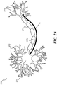
- FIG 2A illustrates a representative human neuron 270.
- the neuron 270 includes a soma 271, from which dendrites 272 and an axon 273 extend.
- the dendrites 272 receive incoming neural impulses (messages) from other cells, and the axon transmits the impulses to still further cells via terminal branches 275.
- a representative neural impulse is illustrated schematically by arrow N in Figure 2A .
- the axon 273 can include a myelin sheath 274 that improves the efficiency with which signals are transmitted along the axon 273, e.g., by restricting or preventing noise or other signals from interfering with the neural impulse N.
- Neuropathic diseases can cause the neuron 270 to degenerate and therefore reduce the ability of the neuron 270 to successfully transmit impulses along the axon 273.
- One source (though not the only source) for neural degeneration includes degeneration of the myelin sheath 274. Aspects of the present technology, described further below, include computationally simulating a degenerated neuron, and then simulating the effect of high frequency signals on the ability of the neuron to transmit impulses.
- Figure 2B schematically illustrates a portion of a computational model of the neuron 270 shown in Figure 2A .
- the model is generally similar to a "McIntyre" model; however, the sodium conductivity constant of the modeled neuron has been reduced from that of a normal neuron, to reflect degeneration of the neuron.
- a typical value for the sodium conductivity constant in a healthy neuron is approximately 3.0 based on recent publications.
- the constant was reduced to 1.8.
- the simulated axon fiber had a diameter of 15 microns.
- the diameter of the axon can have other values typically considered as "large,” e.g. diameters associated with A fibers (alpha: 12-20 ⁇ m, beta: 6-12 ⁇ m, and/or gamma: 1-6 ⁇ m in diameter), but typically not C fibers.
- test pulses or test signals
- test signals neural impulses
- a test signal or test pulse was introduced (e.g., "injected") at an injection node 250.
- inject refers not to a liquid injection but to an electrical signal injection.
- the ability of the axon 273 to transmit the injected test signal can be measured at multiple recording nodes positioned at selected locations along the axon 273 away from the injection node 250. Representative recording nodes are illustrated as a first recording node 251, a second recording node 252, and a third recording node 253. If the test signal is successfully transmitted, the test signal will appear first at the first recording node 251, then at the second recording node 252, and then at the third recording node 253.
- Figure 2C is a graph illustrating the strengths of the signals received at each of the first-third recording nodes 251-253 as a function of time.
- the vertical scale illustrates the millivolt level of the signal, with the resting potential of the neuron 270 at approximately -70 millivolts.
- the horizontal axis identifies the elapsed time (in milliseconds) from an initial signal injection at the injection node 250 ( Figure 2B ).
- Figure 2C illustrates a first response curve 261, a second response curve 262, and a third response curve 263. Each response curve corresponds to a signal recorded at the corresponding recording node 251, 252, 253 respectively ( Figure 2B ).
- the effect of a test pulse initially injected at the injection node 250 is first recorded at the first recording node 251, then at the second recording node 252, and then at the third recording node 253, as indicated by successive spikes in the first, second and third response curves 261, 262, 263, respectively.
- Each successive pulse injected at the injection node 250 produces a corresponding trio of pulses, one at each of the recording nodes 251, 252, 253.
- Figures 3A-3E illustrate the responses produced at the recording nodes shown in Figure 2B , when signals of different frequencies were applied at the injection node 250.
- Figure 3A illustrates the response curves for a test signal injected at the injection node 250 at a frequency of 200 Hz.
- the corresponding first, second, and third response curves 361, 362, and 363 are grouped closely together, and for purposes of illustration and discussion, are referred to as a composite response curve 364.
- the composite response curve 364 can include an initial response period 365a (immediately following the test pulse injection) and a subsequent response period 366a (at a later time).
- the responses of the neuron during the initial and subsequent response periods 365a, 366a were generally similar, and indicate that the neuron accurately tracked and transmitted signals injected at 200 Hz over the course of time.
- Figure 3B illustrates the neural response when the frequency of the test signal applied at the injection node was increased to 400 Hz. As shown in Figure 3B , during an initial response period 365b, the composite neural response curve 364 indicates that the neuron tracked the test signal at the increased frequency, and during a subsequent response period 366b, the neuron did not.
- the frequency of the test signal injected at the injection node 250 ( Figure 2B ) was increased to 600 Hz.
- the neural responses were similar (as indicated by the generally uniform composite response curve 364), but during neither period did the neuron accurately track the rate at which the test pulses were injected at the injection node.
- the composite response curve 364 indicates a response rate of only about 15 pulses during a 50 millisecond interval.
- the frequency of the signal at the injection node was increased to 800 Hz.
- the corresponding neural responses (as indicated by the composite response curve 364) during an initial response period 365d and a subsequent response period 366d illustrate that, again, the neuron failed to track the injected test pulses.
- the frequency of the test signal was increased to 1 kHz and during a corresponding initial response period 365e and subsequent response period 366e, the neuron again failed to keep up with the injected test pulses.
- Figures 3A-3E illustrate that a degenerated neuron may be able to track pulses introduced at a relatively low frequency (e.g., 200 Hz or below), but is unable to accurately track pulses injected at higher frequencies. Such frequencies can occur naturally, particularly in neurons at the spinal cord, which receive inputs from multiple sources.
- Figures 3A-3E also illustrate that the response of the degenerated neuron appears not to be linear. In particular, the qualitative characteristics of the neuron's response change in a non-linear manner, as evidenced by the variations in the composite response curve 364 over Figures 3A-3E .
- Figure 4 schematically illustrates a computationally simulated neuron 270, with a test pulse injection node 450 and a therapy pulse injection node 457.
- Figure 4 also illustrates first and second recording nodes 451, 452, which are located at approximately the same distances from the test pulse injection node 450 as in the model shown in Figure 2B and a third recording node 453 at the other end of the axon 273.
- a therapy signal is injected at the therapy pulse injection node 457.
- the following Figures illustrate the effect of the therapy signal on the ability of the neuron 270 to accurately transmit the test pulses injected at the test pulse injection node 450.
- Figure 5A illustrates a series of test pulses 560a applied at a frequency of 100 Hz, a pulse width of 100 microseconds, and an amplitude set at approximately 80% of the activation threshold of the neuron. Because the pulses were delivered at a subthreshold level, no response was recorded at any of the recording nodes shown in Figure 4 .
- test pulses 560b were again delivered at 100 Hz.
- therapy pulses 567 were delivered at a frequency of 10 kHz.
- the neuron produced responses (illustrated by first, second and third response curves 561, 562, 563 and a composite response curve 564b), over an initial response period 565b, and a subsequent response period 566b.
- the neuron initially transmitted the 100 Hz test pulses, then failed to do so, and then began to transmit the pulses again.
- Figure 5C illustrates the simulated neural response when the frequency of the test pulses 560c was increased to 200 Hz.
- the neuron again tracked the injected test pulses (as indicated by the composite response curve 564c), and then during the subsequent response period 566c, failed to do so.
- the frequency of the test pulses 560d was increased to 400 Hz (as shown in Figure 5D ) the neuron's performance (indicated by the composite response curve 564d) was nearly the same over corresponding initial and subsequent response periods 565d, 566d.
- FIGS. 6A-6C illustrate the result when the amplitude of the therapy signal was increased.
- the amplitude of the therapy signal 667a was set at the baseline level of 50% of threshold, and accordingly, during an initial response period 665a and a subsequent response period 666a, the composite response curve 664a matches the corresponding composite response curve 564b described above with reference to Figure 5B .
- the amplitude of the therapy signal 667b was increased to 60% of threshold.
- the response of the neuron was to produce a continuous composite response curve 668b, illustrating that the neuron accurately tracked the injected test pulses, both during an initial response period 665b and during a subsequent response period 666b.
- the amplitude of the therapy signal 667c was further increased to 70% of threshold (as shown in Figure 6C ) the corresponding continuous composite response curve 668c generally followed the injected test pulses 660, but did so less accurately during an initial period 665c than during a subsequent period 666c. Based on this simulation, it is believed that delivering the therapy signal at an amplitude that is too close to the neuron's threshold amplitude may not produce accurate responses in the neuron.
- Figures 7A and 7B illustrate the effect of increasing the amplitude of the therapy signal when the test pulses 760 were injected at a frequency of 200 Hz rather than 100 Hz.
- a therapy signal 767a was delivered at 50% of threshold
- the neuron produced a composite response curve 764a, that did not sustain an accurate tracking of the test pulses 760 beyond an initial response period 765a.
- Figure 7B when the amplitude of a therapy signal 767b was increased to 60% of threshold, the neuron produced a corresponding continuous composite response curve 768b, accurately tracking the injected test impulses 760 over both an initial response period 765b and a subsequent response period 766b.
- FIG. 8A the neuron produced a composite response curve 864a that does not track each injected test pulse 860 during an initial period 865a, and fails to track nearly all injected test pulses 860 during a subsequent response period 866a.
- Figure 8B when the amplitude of therapy signal 867 was increased to 60% of threshold, the neuron produced a continuous composite response curve 868b, accurately tracking each injected test pulse over both an initial response period 865b and a subsequent response period 866b.
- Figures 6A-8B discussed above, illustrate the effect of therapy signal amplitude, at a frequency of 10 kHz, on the ability of the neuron to accurately transmit injected test pulses.
- Figures 9A-9C illustrate the effect of therapy signal amplitude at different frequencies.
- Figure 9A graphically illustrates test pulses 960 injected at a frequency of 800 Hz, and the corresponding composite response curve 964a (over initial and subsequent response periods 965a, 966a) when the therapy signal 967 was provided at 50% of threshold.
- Figure 9B illustrates the result when the amplitude of the therapy signal 967 was increased to 60% of threshold, producing a continuous composite response curve 968b, generally similar to the continuous composite response curves described above with reference to Figures 6A-8B .
- Figure 9C illustrates the neural response when the frequency of the therapy signal 967 was reduced from 10 kHz to 5 kHz, with the amplitude maintained at 60% of threshold.
- the neuron accurately tracked the injected test pulses during an initial period 965c, but failed to do so during a subsequent period 966c.
- This simulated result illustrates that reducing the frequency of the therapy signal has an effect on the ability of the neuron to accurately track the injected test pulses 960, with all other parameters held constant. It is expected that adjusting other parameters (for example, signal amplitude) may produce a greater beneficial effect than is shown in Figure 9C , and, in at least some embodiments, a beneficial effect equivalent to that shown in Figure 9B .
- the high frequency therapy signal can allow naturally-occurring signals (that are otherwise subthreshold) to trigger an action potential and be transmitted along the axon of the neuron. It is further believed that one aspect of neural degeneration in the patient is that neural signals that are normally suprathreshold are instead subthreshold.
- One potential application of this approach is based on an understanding that, in a degenerative large fiber neuron, normal sensory signal traffic is inhibited (e.g., because the signals are subthreshold rather than suprathreshold). As a result, pain signals (which are transmitted along smaller fibers), may dominate the sensory input received by the patient.
- directing a high frequency therapy signal to the axon of a degenerative neuron can perform one or more of the following functions.
- the signal can rehabilitate the neuron's ability to accurately transmit the naturally occurring signals it receives.
- a patient's ability to respond to a high frequency therapy signal may be evaluated by determining the effect of the high frequency signal on the patient's sensory threshold.
- one effect of the high frequency therapy signal appears to be that it allows transmission of signal traffic that is otherwise inhibited. When such signal traffic is inhibited, the patient fails to receive the sensory inputs. Accordingly, the effect of the high frequency therapy may be to allow the patient to feel sensations that the patient previously could not.
- this effect can be used to screen patients who are likely to respond to high frequency stimulation from those who are not.
- this technique can be used to adjust the parameters of a therapy signal applied to a patient who is already receiving high frequency stimulation. Further details of representative screening and adjustment techniques are described below.
- a representative screening technique can be applied as part of the typical trial (discussed above under Heading 1.0) to reduce the amount of time required to determine whether or not the patient is likely to respond to a high frequency therapy.
- the patient's response to the foregoing sensitivity test is expected to be quicker than (but still indicative of) the patient's response to electrical therapy directed to treat chronic pain.
- the time required to identify patients likely to achieve a successful outcome with a permanent implant can be reduced, e.g., from days to minutes.
- this process can also significantly reduce the time required to identify stimulation parameters (e.g., active electrode combinations, stimulation location, frequency, pulse width, duty cycle, amplitude and/or waveform) for the patient.
- stimulation parameters e.g., active electrode combinations, stimulation location, frequency, pulse width, duty cycle, amplitude and/or waveform
- a successful outcome in this context means identifying the patient as a suitable candidate for an implanted high frequency therapy system.
- the successful outcome can also include identifying stimulation parameters (e.g., optimum stimulation parameters in at least some cases) for use with the implanted high frequency therapy system.
- Figure 10 illustrates a method for both identifying a potentially responsive patient, and administering a therapy to a responsive patient.
- Figure 10 illustrates a representative process 1000 that includes an identification phase 1010 and a therapy phase 1020 which can be performed independently of one another, or successively.
- the process 1000 can include identifying a first (e.g., baseline) sensory threshold of the patient (block 1011). This process can include testing the patient's sensitivity to any suitable sensory input, e.g., a pin prick, pressure, heat, and/or cold.
- the sensory input can be an electrical signal delivered from a skin-mounted electrode (e.g., a TENS electrode) so as to limit the invasiveness of the screening process.
- a skin-mounted electrode e.g., a TENS electrode
- the parameters of the signal can be different than those of the therapy signal.
- the sensory stimulation signal can have a frequency below 1.5 kHz rather than at or above 1.5 kHz.
- the sensory stimulation signal can have a frequency of 1 Hz.
- the amplitude of the sensory stimulation signal can be deliberately ramped up to be suprathreshold, so as produce a sensory response, in order to establish the patient's sensory threshold.
- the sensory input can be delivered by an implanted signal delivery device (e.g., a percutaneous lead or other temporarily or permanently implanted device).
- the sensory input corresponds to the test pulses of the simulations described above.
- the process further includes directing an electrical signal to a neural population of the patient at a frequency in a frequency range of 1.5 kHz to 100 kHz (block 1012). If the patient already has an implanted electrode (e.g., an SCS electrode), the signal can be delivered to the already-implanted electrode, as described above. If the patient does not have an implanted lead or other signal delivery device, the method can include implanting such a signal delivery device as part of the screening process.
- an implanted electrode e.g., an SCS electrode
- the process 1000 can include identifying a second sensory threshold of the patient (block 1013). If the second sensory threshold is less than the first sensory threshold, the process 1000 can include identifying the patient as a candidate for receiving an electrical signal (e.g., an electrical therapy signal) at a frequency in a frequency range of 1.5 kHz to 100 kHz for treatment of pain and/or another disorder (block 1014). Once a suitable candidate has been identified using the foregoing technique, the patient's pain (or other disorder) can be addressed by applying the therapy signal, as indicated in phase 1020. Phase 1020 can include providing the patient with a therapeutic benefit via an electrical signal (e.g., an electrical therapy signal).
- an electrical signal e.g., an electrical therapy signal
- phase 1020 can include increasing a throughput of naturally occurring signals along the patient's large neural fibers by applying an electrical signal to the fibers at a frequency in a frequency range of 1.5 kHz to 100 kHz, at a subthreshold amplitude (block 1021).
- a particular practitioner may perform only phase 1010, only phase 1020, or both phases 1010 and 1020 on any given patient, depending, for example, on the characteristics of the patient and/or prior treatments the patient may have received.
- a representative process 1100 can include directing a first electrical signal to a neural population of the patient in accordance with a first set of signal delivery parameters, including a frequency in a frequency range of 1.5 kHz to 100 kHz (block 1110). Accordingly, block 1110 can refer to a patient receiving a high frequency therapy to address pain or another indication.
- the process 1100 can further include identifying a first sensory threshold of the patient (block 1112) e.g., using any of the techniques described above with reference to block 1011. Because the patient is already receiving a high frequency electrical therapy signal, the device used to deliver the therapy signal can also be used to deliver a sensory stimulation signal. For example, an existing implanted signal delivery device can be used to deliver the sensory stimulation signal. In other embodiments, another device (e.g., a TENS device) can be used to deliver the sensory stimulation signal.
- a TENS device can be used to deliver the sensory stimulation signal.
- the process 1100 can further include changing the electrical therapy signal applied to the patient, for example, if the patient is no longer receiving a therapeutic benefit from the first electrical signal, or if it is expected that the patient can receive additional benefit from an electrical signal having different parameters.
- the process can include directing a second electrical signal to the patient in accordance with a second set of signal delivery parameters different than the first (block 1114).
- the "different" means that any one parameter in accordance with which the second electrical signal is delivered is different than a corresponding parameter in accordance with which the first electrical signal was delivered.
- the second electrical signal can have a different amplitude, a different pulse width, a different frequency, a different duty cycle, and/or a different delivery location than that of the first electrical signal.
- the process 1100 includes identifying a second sensory threshold of the patient, while (and/or after) delivering the second electrical signal to the patient.
- block 1116 can correspond generally to block 1013 described above. If the second sensory threshold is less than the first sensory threshold, the process can include directing an electrical therapy signal to the patient in accordance with the second set of signal delivery parameters (block 1118). Accordingly, as was discussed above in the context of the screening process shown in Figure 10 , the process shown in Figure 11 can shorten the time required to identify new stimulation parameters by using a real-time or near real-time change in the patient's sensory threshold, rather than waiting (what is typically a longer period of time) for the patient to exhibit a reduction in pain or other therapeutic response.
- Figure 12 is a partially schematic illustration of a representative signal delivery device 1210 suitable for delivering therapy signals and/or other electrical signals (e.g., test signals or sensory stimulation signals) to the patient.
- the signal delivery device 1210 can have a paddle-type configuration, and can accordingly include a paddle body 1211 having multiple signal delivery contacts 1215.
- the signal delivery contacts 1215 can include one or more contacts that are selected to deliver sensory stimulation signals (e.g., to determine the patient's sensory threshold) and one or more contacts selected to deliver an electrical therapy signal (e.g., to provide a therapeutic benefit to the patient).
- a pair of first contacts 1215a can be used to deliver sensory stimulation signals, and any of the remaining second contacts 1215b can be used to apply a therapy signal to the patient.
- the first contacts 1215a are different than the second contacts so as to avoid overlapping the effects of the sensory stimulation signal and a (potentially) therapeutic signal.
- the same contact(s) can be used to deliver the sensory stimulation signals and the therapy signals.
- the signal delivery device can have other configurations, for example, configurations similar to those described above with reference to Figures 1A and 1B .
- Figure 13 illustrates a representative pair of signal delivery devices 1310, including a first lead or lead body 1311a, and a second lead or lead body 1311b.
- the lead or leads 1311 can include multiple signal delivery contacts 1315, and, in a manner generally similar to that discussed above, the signal delivery contacts 1315 can include first signal delivery contacts 1315a used to deliver sensory stimulation signals, and second signal delivery contacts 1315b used to deliver therapy signals.
- the signal delivery devices discussed above with reference to Figures 12 and 13 can be coupled to a signal generator for patient treatment and/or screening.
- a representative system (to which the signal delivery devices can be connected) includes a signal generator that in turn includes signal generation circuitry, for example, as described above with reference to Figure 1A .
- the system can further include a computer readable medium operatively coupled to the signal generation circuitry and programmed with instructions.
- the instructions can perform a process 1400.
- the process 1400 can include directing a first, sensory stimulation signal to the patient to elicit a first sensory response.
- the process can include receiving an indication of a first sensory threshold of the patient corresponding to the first sensory stimulation signal.
- the amplitude of the first sensory stimulation signal can be increased until it triggers a sensory response in the patient, which corresponds to the first sensory threshold, and which may be entered into the system by the patient or a practitioner, or determined automatically (e.g., when the patient or practitioner ceases increasing the signal amplitude).
- the process can further include directing an electrical signal to a neural population of the patient at a frequency in a frequency range of 1.5 kHz to 100 kHz (block 1406).
- the process includes directing a second sensory stimulation signal to the patient to elicit a second sensory response, while (and/or after) directing the electrical signal to the patient.
- Block 1410 includes receiving an indication of a second sensory threshold of the patient corresponding to the second sensory stimulation signal. The indication can be received in any of the manners described above with reference to block 1404.
- the process includes determining whether the second sensory threshold is less than the first sensory threshold. If it is, the process can continue to block 1414 or block 1416.
- Block 1414 includes identifying the patient as a candidate for receiving an electrical therapy signal at a frequency in a frequency range of 1.5 kHz to 100 kHz, in response to the indication that the second sensory threshold is less than the first.
- the process can include changing a signal delivery parameter in accordance with which the patient receives therapy via the electrical signal. Accordingly, block 1414 corresponds to using the results of the sensory stimulation process to screen the patient, and block 1416 includes using the results to adjust the patient's therapy parameters.
- the patient may receive high frequency therapeutic signals with at least a portion of the therapy signal at a frequency from about 1.5 kHz to about 100 kHz, or from about 1.5 kHz to about 50 kHz, or from about 3 kHz to about 20 kHz, or from about 5 kHz to about 15 kHz, or from about 1.5 kHz to about 10 kHz, or at frequencies of about 8 kHz, 9 kHz, or 10 kHz.
- representative current amplitudes for the therapy signal are from 0.1 mA to 20 mA, or 0.5 mA to 10 mA, or 0.5 mA to 7 mA, or 0.5 mA to 5 mA.
- Representative pulse widths range from about 10 microseconds to about 333 microseconds, about 10 microseconds to about 166 microseconds, 20 microseconds to about 100 microseconds, 30 microseconds to about 100 microseconds, and 30 microseconds to about 40 microseconds.
- Duty cycles can range from about 10% to about 100%, and in a particular duty cycle, signals are delivered for 20 seconds and interrupted for 2 minutes (an approximately 14% duty cycle). In other embodiments, these parameters can have other suitable values.
- a method for treating a patient in accordance with a particular embodiment of the present technology includes increasing a throughput of naturally occurring signals along the patient's large neural fibers by applying an electrical signal to the fibers at a frequency in a frequency range of 1.5 kHz to 100 kHz, and a subthreshold amplitude.
- the large fibers can include A fibers, but not C fibers.
- the threshold amplitude is below the patient's sensory threshold.
- the fibers can be peripheral nerve fibers, and/or can be located at the patient's spinal cord.
- the signal is applied to the axons.
- Another representative embodiment includes a method for identifying a patient as a candidate for pain treatment.
- the method can include identifying a first sensory threshold of the patient, directing an electrical signal to a neural population of the patient at a frequency in a frequency range of 1.5 kHz to 100 kHz, and identifying a second sensory threshold of the patient, while or after directing the electrical signal to the patient. If the second sensory threshold is less than the first sensory threshold, the method can include identifying the patient as a candidate for receiving an electrical therapy signal at a frequency in a frequency range of 1.5 kHz to 100 kHz, for example, to treat pain.
- the first sensory threshold can be identified by applying a test signal via an implanted device, e.g. to a peripheral nerve of the patient, or to the patient's spinal cord.
- the test signal can be applied to the patient's skin.
- the method can be directed to adjusting an existing patient therapy regimen.
- a representative method can include directing a first electrical signal to a neural population of the patient in accordance with a first set of signal delivery parameters, including a frequency in a frequency range of 1.5 kHz to 100 kHz.
- the method can further include identifying a first sensory threshold of the patient, and directing a second electrical signal to the patient in accordance with a second set of signal delivery parameters different than the first.
- the method can still further include identifying a second sensory threshold of the patient, while or after delivering the second electrical signal to the patient. If the second sensory threshold is less than the first, the method can include directing an electrical therapy signal to the patient in accordance with the second set of signal delivery parameters.
- the technology includes systems for treating a patient.
- a representative system includes a signal generator that in turn includes signal generation circuitry and a computer readable medium.
- the computer readable medium is operatively coupled to the signal generation circuitry and is programmed with instructions that when executed direct a first, sensory stimulation signal to the patient to elicit a first sensory response, and receive an indication of a first sensory threshold of the patient corresponding to the first sensory stimulation signal.
- the instructions can further include directing an electrical signal to a neural population of the patient at a frequency in a frequency range of 1.5 kHz to 100 kHz, and directing a second sensory stimulation signal to the patient to elicit a second sensory response, while or after directing the electrical signal to the patient.
- the instructions can further include receiving an indication of a second sensory threshold of the patient corresponding to the second sensory stimulation signal and, if the second sensory threshold is less than the first, performing at least one of the following actions.
- a first action includes identifying a patient as a candidate for receiving an electrical therapy signal at a frequency in a frequency range of 1.5 kHz to 100 kHz, and a second action includes changing a signal delivery parameter in accordance with which the patient receives therapy via the electrical signal.
- the signal generator includes an implantable signal generator, and at least a portion of the computer readable medium is carried by the implantable signal generator. In other embodiments, at least a portion of the computer readable medium is external to the implantable signal generator.
- the first sensory stimulation signal can have a frequency of less than 1500 Hz, for example, 1 Hz.
- the process of screening a patient can be conducted separately from the process of treating the patient using a high frequency therapy signal.
- the process of screening the patient may be conducted without applying a therapy to the patient, for example, if the patient fails the screening test.
- advantages associated with certain embodiments of the disclosed technology have been described in the context of those embodiments, other embodiments may also exhibit such advantages, and not all embodiments need necessarily exhibit such advantages to fall within the scope of the present technology. Accordingly, the disclosure and associated technology can encompass other embodiments not expressly shown or described herein.
Landscapes
- Health & Medical Sciences (AREA)
- Life Sciences & Earth Sciences (AREA)
- Neurology (AREA)
- General Health & Medical Sciences (AREA)
- Veterinary Medicine (AREA)
- Public Health (AREA)
- Engineering & Computer Science (AREA)
- Biomedical Technology (AREA)
- Nuclear Medicine, Radiotherapy & Molecular Imaging (AREA)
- Radiology & Medical Imaging (AREA)
- Animal Behavior & Ethology (AREA)
- Neurosurgery (AREA)
- Orthopedic Medicine & Surgery (AREA)
- Physiology (AREA)
- Biophysics (AREA)
- Pain & Pain Management (AREA)
- Heart & Thoracic Surgery (AREA)
- Cardiology (AREA)
- Electrotherapy Devices (AREA)
- Measurement And Recording Of Electrical Phenomena And Electrical Characteristics Of The Living Body (AREA)
Priority Applications (1)
| Application Number | Priority Date | Filing Date | Title |
|---|---|---|---|
| EP22185588.5A EP4147745A1 (fr) | 2016-03-30 | 2017-03-30 | Systèmes pour identifier et traiter des patients avec des signaux électriques à haute fréquence |
Applications Claiming Priority (2)
| Application Number | Priority Date | Filing Date | Title |
|---|---|---|---|
| US201662315569P | 2016-03-30 | 2016-03-30 | |
| US15/470,027 US10799701B2 (en) | 2016-03-30 | 2017-03-27 | Systems and methods for identifying and treating patients with high-frequency electrical signals |
Related Child Applications (1)
| Application Number | Title | Priority Date | Filing Date |
|---|---|---|---|
| EP22185588.5A Division EP4147745A1 (fr) | 2016-03-30 | 2017-03-30 | Systèmes pour identifier et traiter des patients avec des signaux électriques à haute fréquence |
Publications (3)
| Publication Number | Publication Date |
|---|---|
| EP3257552A2 true EP3257552A2 (fr) | 2017-12-20 |
| EP3257552A3 EP3257552A3 (fr) | 2018-03-21 |
| EP3257552B1 EP3257552B1 (fr) | 2022-07-20 |
Family
ID=59999855
Family Applications (2)
| Application Number | Title | Priority Date | Filing Date |
|---|---|---|---|
| EP22185588.5A Withdrawn EP4147745A1 (fr) | 2016-03-30 | 2017-03-30 | Systèmes pour identifier et traiter des patients avec des signaux électriques à haute fréquence |
| EP17163934.7A Active EP3257552B1 (fr) | 2016-03-30 | 2017-03-30 | Systèmes pour identifier et traiter des patients avec des signaux électriques à haute fréquence |
Family Applications Before (1)
| Application Number | Title | Priority Date | Filing Date |
|---|---|---|---|
| EP22185588.5A Withdrawn EP4147745A1 (fr) | 2016-03-30 | 2017-03-30 | Systèmes pour identifier et traiter des patients avec des signaux électriques à haute fréquence |
Country Status (3)
| Country | Link |
|---|---|
| US (3) | US10799701B2 (fr) |
| EP (2) | EP4147745A1 (fr) |
| AU (3) | AU2017202068B2 (fr) |
Families Citing this family (24)
| Publication number | Priority date | Publication date | Assignee | Title |
|---|---|---|---|---|
| US11413458B2 (en) | 2011-05-19 | 2022-08-16 | Neuros Medical, Inc. | Nerve cuff electrode for neuromodulation in large human nerve trunks |
| US9833614B1 (en) | 2012-06-22 | 2017-12-05 | Nevro Corp. | Autonomic nervous system control via high frequency spinal cord modulation, and associated systems and methods |
| US11045649B2 (en) | 2016-02-19 | 2021-06-29 | Medtronic, Inc. | Incontinence therapy |
| US11446504B1 (en) | 2016-05-27 | 2022-09-20 | Nevro Corp. | High frequency electromagnetic stimulation for modulating cells, including spontaneously active and quiescent cells, and associated systems and methods |
| US20180272132A1 (en) | 2017-01-19 | 2018-09-27 | Nevro Corp. | High frequency stimulation for treating sensory and/or motor deficits in patients with spinal cord injuries and/or peripheral polyneuropathy, and associated systems and methods |
| US12357828B2 (en) | 2017-12-05 | 2025-07-15 | Ecole Polytechnique Federale De Lausanne (Epfl) | System for planning and/or providing neuromodulation |
| KR102648346B1 (ko) | 2017-12-13 | 2024-03-15 | 뉴로스 메디컬 인코포레이티드 | 신경 커프 배치 장치 |
| WO2019191601A1 (fr) | 2018-03-29 | 2019-10-03 | Nevro Corp. | Modulation thérapeutique pour traiter les anomalies de glycémie, y compris le diabète de type 2, et/ou pour réduire les niveaux d'hba1c, et systèmes et méthodes associés |
| CN112188915A (zh) | 2018-04-09 | 2021-01-05 | 纽若斯医疗公司 | 用于设置电剂量的装置和方法 |
| EP3574952B1 (fr) * | 2018-05-30 | 2020-11-25 | G-Therapeutics BV | Réseau d'électrodes, palette de branchement et système de neuromodulation |
| EP3653260A1 (fr) | 2018-11-13 | 2020-05-20 | GTX medical B.V. | Capteur dans des vêtements de membre ou une chaussure |
| US11602634B2 (en) | 2019-01-17 | 2023-03-14 | Nevro Corp. | Sensory threshold adaptation for neurological therapy screening and/or electrode selection, and associated systems and methods |
| US11590352B2 (en) | 2019-01-29 | 2023-02-28 | Nevro Corp. | Ramped therapeutic signals for modulating inhibitory interneurons, and associated systems and methods |
| GB201901982D0 (en) * | 2019-02-13 | 2019-04-03 | Univ Oxford Innovation Ltd | Emulation of electrophysiological signals derived by stimulation of a body |
| US11065461B2 (en) | 2019-07-08 | 2021-07-20 | Bioness Inc. | Implantable power adapter |
| US11638821B2 (en) | 2019-07-30 | 2023-05-02 | Medtronic, Inc. | Incontinence therapy |
| US11311729B2 (en) | 2019-07-30 | 2022-04-26 | Medtronic, Inc. | Titration for sub-threshold electrical stimulation therapy |
| US11383086B2 (en) | 2019-07-30 | 2022-07-12 | Medtronic, Inc. | Posture-based paresthesia threshold or perception threshold determination |
| EP3824948A1 (fr) | 2019-11-19 | 2021-05-26 | ONWARD Medical B.V. | Système de planification et/ou de commande pour un système de neuromodulation |
| EP3827875B1 (fr) | 2019-11-27 | 2023-07-05 | ONWARD Medical N.V. | Systeme de neuromodulation |
| EP4103267B1 (fr) | 2020-02-11 | 2025-06-04 | Neuros Medical, Inc. | Système de quantification d'ensembles de données qualitatives rapportées par un patient |
| US12329971B2 (en) | 2021-07-16 | 2025-06-17 | Saluda Medical Pty Ltd | Adaptation of neurostimulation therapy to age-related physiological changes |
| EP4547322A1 (fr) | 2022-07-01 | 2025-05-07 | Nevro Corporation | Neurostimulation pour le traitement de déficits sensoriels, et systèmes et méthodes associés |
| CN116350945B (zh) * | 2023-06-01 | 2023-08-04 | 泉州艾奇科技有限公司 | 脉冲输出方法、控制器、按摩仪及存储介质 |
Citations (5)
| Publication number | Priority date | Publication date | Assignee | Title |
|---|---|---|---|---|
| US20090204173A1 (en) | 2007-11-05 | 2009-08-13 | Zi-Ping Fang | Multi-Frequency Neural Treatments and Associated Systems and Methods |
| US20100274317A1 (en) | 2009-04-22 | 2010-10-28 | Jon Parker | Devices for controlling high frequency spinal cord modulation for inhibiting pain, and associated systems and methods, including simplified contact selection |
| US20110071593A1 (en) | 2009-09-18 | 2011-03-24 | Nevro Corporation | Couplings for implanted leads and external stimulators, and associated systems and methods |
| US8355797B2 (en) | 2009-02-10 | 2013-01-15 | Nevro Corporation | Systems and methods for delivering neural therapy correlated with patient status |
| US20130066411A1 (en) | 2011-09-08 | 2013-03-14 | James R. Thacker | Selective high frequency spinal cord modulation for inhibiting pain, including cephalic and/or total body pain with reduced side effects, and associated systems and methods |
Family Cites Families (197)
| Publication number | Priority date | Publication date | Assignee | Title |
|---|---|---|---|---|
| US1597061A (en) | 1924-10-20 | 1926-08-24 | James A Cultra | Electrotherapeutic appliance |
| BE487066A (fr) | 1947-12-08 | |||
| US3195540A (en) | 1963-03-29 | 1965-07-20 | Louis C Waller | Power supply for body implanted instruments |
| US3817254A (en) | 1972-05-08 | 1974-06-18 | Medtronic Inc | Transcutaneous stimulator and stimulation method |
| US3822708A (en) | 1972-12-07 | 1974-07-09 | Clinical Technology Corp | Electrical spinal cord stimulating device and method for management of pain |
| US3893463A (en) | 1973-12-07 | 1975-07-08 | Medtronic Inc | Dual channel stimulator |
| AT332528B (de) | 1974-10-18 | 1976-10-11 | Nemec Hans | Elektromedizinischer apparat |
| US4055190A (en) | 1974-12-19 | 1977-10-25 | Michio Tany | Electrical therapeutic apparatus |
| US4014347A (en) | 1975-05-27 | 1977-03-29 | Staodynamics, Inc. | Transcutaneous nerve stimulator device and method |
| US4535777A (en) | 1981-08-20 | 1985-08-20 | Physio Technology, Inc. | Method of providing electrical stimulation of tissue |
| US4414986A (en) | 1982-01-29 | 1983-11-15 | Medtronic, Inc. | Biomedical stimulation lead |
| CA1215128A (fr) | 1982-12-08 | 1986-12-09 | Pedro Molina-Negro | Appareil de stimulation electrique des nerfs |
| US4649935A (en) | 1984-05-21 | 1987-03-17 | Symtonic Sa | Method of treating neurovegetative disorders and apparatus therefor |
| USRE33420E (en) | 1984-09-17 | 1990-11-06 | Cordis Corporation | System for controlling an implanted neural stimulator |
| US4608985A (en) | 1984-10-11 | 1986-09-02 | Case Western Reserve University | Antidromic pulse generating wave form for collision blocking |
| US4841973A (en) | 1987-09-21 | 1989-06-27 | Stecker Harold D | Electrical stimulators |
| US5002053A (en) | 1989-04-21 | 1991-03-26 | University Of Arkansas | Method of and device for inducing locomotion by electrical stimulation of the spinal cord |
| US5335657A (en) | 1991-05-03 | 1994-08-09 | Cyberonics, Inc. | Therapeutic treatment of sleep disorder by nerve stimulation |
| EP0532143A1 (fr) | 1991-09-12 | 1993-03-17 | BIOTRONIK Mess- und Therapiegeräte GmbH & Co Ingenieurbüro Berlin | Neurostimulateur |
| GB9211085D0 (en) | 1992-05-23 | 1992-07-08 | Tippey Keith E | Electrical stimulation |
| GB9302335D0 (en) | 1993-02-05 | 1993-03-24 | Macdonald Alexander J R | Electrotherapeutic apparatus |
| US5501703A (en) | 1994-01-24 | 1996-03-26 | Medtronic, Inc. | Multichannel apparatus for epidural spinal cord stimulator |
| US5514175A (en) | 1994-11-09 | 1996-05-07 | Cerebral Stimulation, Inc. | Auricular electrical stimulator |
| CA2229391C (fr) | 1995-04-10 | 2005-09-27 | Admir Hadzic | Dispositif de stimulation de nerfs peripheriques pour le blocage de nerfs sans assistance |
| US7393351B2 (en) | 1995-06-07 | 2008-07-01 | Arthrocare Corporation | Apparatus and methods for treating cervical inter-vertebral discs |
| US5806522A (en) | 1995-08-15 | 1998-09-15 | Katims; Jefferson Jacob | Digital automated current perception threshold (CPT) determination device and method |
| CA2171067A1 (fr) | 1996-03-05 | 1997-09-06 | The Governors Of The University Of Alberta | Prothese neuronale |
| US6505078B1 (en) | 1996-04-04 | 2003-01-07 | Medtronic, Inc. | Technique for adjusting the locus of excitation of electrically excitable tissue |
| US6246912B1 (en) | 1996-06-27 | 2001-06-12 | Sherwood Services Ag | Modulated high frequency tissue modification |
| US5983141A (en) | 1996-06-27 | 1999-11-09 | Radionics, Inc. | Method and apparatus for altering neural tissue function |
| US5853373A (en) | 1996-08-05 | 1998-12-29 | Becton, Dickinson And Company | Bi-level charge pulse apparatus to facilitate nerve location during peripheral nerve block procedures |
| US6026326A (en) | 1997-01-13 | 2000-02-15 | Medtronic, Inc. | Apparatus and method for treating chronic constipation |
| US5836994A (en) | 1997-04-30 | 1998-11-17 | Medtronic, Inc. | Method and apparatus for electrical stimulation of the gastrointestinal tract |
| US5893883A (en) | 1997-04-30 | 1999-04-13 | Medtronic, Inc. | Portable stimulation screening device for screening therapeutic effect of electrical stimulation on a patient user during normal activities of the patient user |
| IL133902A0 (en) | 1997-07-16 | 2001-04-30 | Impulse Dynamics Ltd | Smooth muscle controller |
| US6014588A (en) | 1998-04-07 | 2000-01-11 | Fitz; William R. | Facet joint pain relief method and apparatus |
| US6421566B1 (en) | 1998-04-30 | 2002-07-16 | Medtronic, Inc. | Selective dorsal column stimulation in SCS, using conditioning pulses |
| US6120467A (en) | 1998-04-30 | 2000-09-19 | Medtronic Inc. | Spinal cord simulation systems with patient activity monitoring and therapy adjustments |
| US6319241B1 (en) | 1998-04-30 | 2001-11-20 | Medtronic, Inc. | Techniques for positioning therapy delivery elements within a spinal cord or a brain |
| US8626302B2 (en) | 1998-06-03 | 2014-01-07 | Spr Therapeutics, Llc | Systems and methods to place one or more leads in muscle for providing electrical stimulation to treat pain |
| US7890176B2 (en) | 1998-07-06 | 2011-02-15 | Boston Scientific Neuromodulation Corporation | Methods and systems for treating chronic pelvic pain |
| US6027456A (en) | 1998-07-10 | 2000-02-22 | Advanced Neuromodulation Systems, Inc. | Apparatus and method for positioning spinal cord stimulation leads |
| US6002964A (en) | 1998-07-15 | 1999-12-14 | Feler; Claudio A. | Epidural nerve root stimulation |
| US6161044A (en) | 1998-11-23 | 2000-12-12 | Synaptic Corporation | Method and apparatus for treating chronic pain syndromes, tremor, dementia and related disorders and for inducing electroanesthesia using high frequency, high intensity transcutaneous electrical nerve stimulation |
| US6909917B2 (en) | 1999-01-07 | 2005-06-21 | Advanced Bionics Corporation | Implantable generator having current steering means |
| US6341236B1 (en) | 1999-04-30 | 2002-01-22 | Ivan Osorio | Vagal nerve stimulation techniques for treatment of epileptic seizures |
| US6176242B1 (en) | 1999-04-30 | 2001-01-23 | Medtronic Inc | Method of treating manic depression by brain infusion |
| US6923784B2 (en) | 1999-04-30 | 2005-08-02 | Medtronic, Inc. | Therapeutic treatment of disorders based on timing information |
| US6167311A (en) | 1999-06-14 | 2000-12-26 | Electro Core Techniques, Llc | Method of treating psychological disorders by brain stimulation within the thalamus |
| US6233488B1 (en) | 1999-06-25 | 2001-05-15 | Carl A. Hess | Spinal cord stimulation as a treatment for addiction to nicotine and other chemical substances |
| US6516227B1 (en) | 1999-07-27 | 2003-02-04 | Advanced Bionics Corporation | Rechargeable spinal cord stimulator system |
| AU1618401A (en) | 1999-12-06 | 2001-06-12 | Advanced Bionics Corporation | Implantable device programmer |
| JP2003516206A (ja) | 1999-12-07 | 2003-05-13 | クラスノウ インスティテュート | 神経系の適応性電場調整 |
| EP1246665B1 (fr) | 2000-01-07 | 2005-08-24 | Biowave Corporation | Dispositifs d'electrotherapie |
| US6356786B1 (en) | 2000-01-20 | 2002-03-12 | Electrocore Techniques, Llc | Method of treating palmar hyperhydrosis by electrical stimulation of the sympathetic nervous chain |
| US6885888B2 (en) | 2000-01-20 | 2005-04-26 | The Cleveland Clinic Foundation | Electrical stimulation of the sympathetic nerve chain |
| US6609030B1 (en) | 2000-02-24 | 2003-08-19 | Electrocore Techniques, Llc | Method of treating psychiatric diseases by neuromodulation within the dorsomedial thalamus |
| US7082333B1 (en) | 2000-04-27 | 2006-07-25 | Medtronic, Inc. | Patient directed therapy management |
| US20020055688A1 (en) | 2000-05-18 | 2002-05-09 | Jefferson Jacob Katims | Nervous tissue stimulation device and method |
| US6510347B2 (en) | 2000-08-17 | 2003-01-21 | William N. Borkan | Spinal cord stimulation leads |
| US6871099B1 (en) | 2000-08-18 | 2005-03-22 | Advanced Bionics Corporation | Fully implantable microstimulator for spinal cord stimulation as a therapy for chronic pain |
| US6405079B1 (en) | 2000-09-22 | 2002-06-11 | Mehdi M. Ansarinia | Stimulation method for the dural venous sinuses and adjacent dura for treatment of medical conditions |
| US6871090B1 (en) | 2000-10-13 | 2005-03-22 | Advanced Bionics Corporation | Switching regulator for implantable spinal cord stimulation |
| US6950707B2 (en) | 2000-11-21 | 2005-09-27 | Advanced Bionics Corporation | Systems and methods for treatment of obesity and eating disorders by electrical brain stimulation and/or drug infusion |
| US20050143789A1 (en) | 2001-01-30 | 2005-06-30 | Whitehurst Todd K. | Methods and systems for stimulating a peripheral nerve to treat chronic pain |
| US7493172B2 (en) | 2001-01-30 | 2009-02-17 | Boston Scientific Neuromodulation Corp. | Methods and systems for stimulating a nerve originating in an upper cervical spine area to treat a medical condition |
| US8060208B2 (en) | 2001-02-20 | 2011-11-15 | Case Western Reserve University | Action potential conduction prevention |
| US7389145B2 (en) | 2001-02-20 | 2008-06-17 | Case Western Reserve University | Systems and methods for reversibly blocking nerve activity |
| US20020128700A1 (en) | 2001-03-08 | 2002-09-12 | Cross Thomas E. | Lead with adjustable angular and spatial relationships between electrodes |
| US6907295B2 (en) | 2001-08-31 | 2005-06-14 | Biocontrol Medical Ltd. | Electrode assembly for nerve control |
| US6928320B2 (en) | 2001-05-17 | 2005-08-09 | Medtronic, Inc. | Apparatus for blocking activation of tissue or conduction of action potentials while other tissue is being therapeutically activated |
| WO2003015863A2 (fr) | 2001-08-17 | 2003-02-27 | Advanced Bionics Corporation | Recrutement progressif de tissu musculaire/nerveux excitable par utilisation de parametres de stimulation electrique haut debit |
| WO2003033070A1 (fr) | 2001-10-16 | 2003-04-24 | Case Western Reserve University | Prothese neurale |
| US7288062B2 (en) | 2001-11-09 | 2007-10-30 | Michael Spiegel | Apparatus for creating therapeutic charge transfer in tissue |
| US6721603B2 (en) | 2002-01-25 | 2004-04-13 | Cyberonics, Inc. | Nerve stimulation as a treatment for pain |
| US8233991B2 (en) | 2002-02-04 | 2012-07-31 | Boston Scientific Neuromodulation Corporation | Method for programming implantable device |
| US9364281B2 (en) | 2002-03-05 | 2016-06-14 | Avent, Inc. | Methods for treating the thoracic region of a patient's body |
| US7239912B2 (en) | 2002-03-22 | 2007-07-03 | Leptos Biomedical, Inc. | Electric modulation of sympathetic nervous system |
| US7236822B2 (en) | 2002-03-22 | 2007-06-26 | Leptos Biomedical, Inc. | Wireless electric modulation of sympathetic nervous system |
| US7937145B2 (en) | 2002-03-22 | 2011-05-03 | Advanced Neuromodulation Systems, Inc. | Dynamic nerve stimulation employing frequency modulation |
| US7024246B2 (en) | 2002-04-26 | 2006-04-04 | Medtronic, Inc | Automatic waveform output adjustment for an implantable medical device |
| US6968237B2 (en) | 2002-05-22 | 2005-11-22 | Pacesetter, Inc. | Implantable coronary sinus lead and lead system |
| US7251529B2 (en) | 2002-05-29 | 2007-07-31 | Oklahoma Foundation For Digestive Research | Spinal cord stimulation as treatment for functional bowel disorders |
| US20040015202A1 (en) | 2002-06-14 | 2004-01-22 | Chandler Gilbert S. | Combination epidural infusion/stimulation method and system |
| US7860570B2 (en) | 2002-06-20 | 2010-12-28 | Boston Scientific Neuromodulation Corporation | Implantable microstimulators and methods for unidirectional propagation of action potentials |
| US7047079B2 (en) | 2002-07-26 | 2006-05-16 | Advanced Neuromodulation Systems, Inc. | Method and system for energy conservation in implantable stimulation devices |
| US20040210270A1 (en) | 2002-07-26 | 2004-10-21 | John Erickson | High frequency pulse generator for an implantable neurostimulator |
| EP1551499A1 (fr) | 2002-10-04 | 2005-07-13 | Microchips, Inc. | Dispositif medical de stimulation nerveuse et d'administration controlee de medicaments |
| EP1575664B1 (fr) | 2002-12-06 | 2010-02-17 | Boston Scientific Neuromodulation Corporation | Procede de determination de parametres de stimulation |
| US6990376B2 (en) | 2002-12-06 | 2006-01-24 | The Regents Of The University Of California | Methods and systems for selective control of bladder function |
| US7933654B2 (en) | 2002-12-17 | 2011-04-26 | Massachusetts Eye & Ear Infirmary | Vestibular stimulator |
| US20040162590A1 (en) | 2002-12-19 | 2004-08-19 | Whitehurst Todd K. | Fully implantable miniature neurostimulator for intercostal nerve stimulation as a therapy for angina pectoris |
| EP1587576A2 (fr) | 2003-01-03 | 2005-10-26 | Advanced Neuromodulation Systems Inc. | Systeme et procede pour stimuler le tronc cerebral d'une personne |
| WO2004064915A2 (fr) | 2003-01-22 | 2004-08-05 | International Rehabilitative Sciences, Inc. | Stimulation de la moelle epiniere par un courant interferentiel |
| US7444183B2 (en) | 2003-02-03 | 2008-10-28 | Enteromedics, Inc. | Intraluminal electrode apparatus and method |
| US7266412B2 (en) | 2003-04-22 | 2007-09-04 | Medtronic, Inc. | Generation of multiple neurostimulation therapy programs |
| US7463928B2 (en) | 2003-04-25 | 2008-12-09 | Medtronic, Inc. | Identifying combinations of electrodes for neurostimulation therapy |
| US7149574B2 (en) | 2003-06-09 | 2006-12-12 | Palo Alto Investors | Treatment of conditions through electrical modulation of the autonomic nervous system |
| CA2530396C (fr) | 2003-06-24 | 2015-03-24 | Healthonics, Inc. | Appareil et procede de stimulation bioelectrique, d'acceleration de la cicatrisation, de soulagement de la douleur ou de devitalisation d'agents pathogenes |
| WO2005007238A1 (fr) | 2003-07-18 | 2005-01-27 | Campbell James N | Traitement de la douleur |
| US20050038489A1 (en) | 2003-08-14 | 2005-02-17 | Grill Warren M. | Electrode array for use in medical stimulation and methods thereof |
| US8396565B2 (en) | 2003-09-15 | 2013-03-12 | Medtronic, Inc. | Automatic therapy adjustments |
| US7252090B2 (en) | 2003-09-15 | 2007-08-07 | Medtronic, Inc. | Selection of neurostimulator parameter configurations using neural network |
| US7206632B2 (en) * | 2003-10-02 | 2007-04-17 | Medtronic, Inc. | Patient sensory response evaluation for neuromodulation efficacy rating |
| US20050153885A1 (en) | 2003-10-08 | 2005-07-14 | Yun Anthony J. | Treatment of conditions through modulation of the autonomic nervous system |
| WO2005051480A2 (fr) | 2003-11-20 | 2005-06-09 | Advanced Neuromodulation Systems, Inc. | Systeme de stimulation electrique, cable et methode permettant d'obtenir des effets de neuroplasticite reduits |
| US20060161219A1 (en) | 2003-11-20 | 2006-07-20 | Advanced Neuromodulation Systems, Inc. | Electrical stimulation system and method for stimulating multiple locations of target nerve tissue in the brain to treat multiple conditions in the body |
| US7744553B2 (en) | 2003-12-16 | 2010-06-29 | Baxter International Inc. | Medical fluid therapy flow control systems and methods |
| US7676269B2 (en) | 2003-12-29 | 2010-03-09 | Palo Alto Investors | Treatment of female fertility conditions through modulation of the autonomic nervous system |
| CA2553901C (fr) | 2004-01-22 | 2015-01-20 | Rehabtronics Inc. | Procede d'acheminement de courant electrique a des tissus corporels via des conducteurs passifs implantes |
| US20100016929A1 (en) | 2004-01-22 | 2010-01-21 | Arthur Prochazka | Method and system for controlled nerve ablation |
| WO2005082453A1 (fr) | 2004-02-25 | 2005-09-09 | Advanced Neuromodulation Systems, Inc. | Systeme et procede permettant d'effectuer une stimulation neurologique de nerfs peripheriques pour traiter une lombalgie |
| WO2005087314A1 (fr) | 2004-03-11 | 2005-09-22 | Advanced Neuromodulation Systems, Inc. | Systeme et procede de stimulation du cerveau |
| US7177702B2 (en) | 2004-03-12 | 2007-02-13 | Scimed Life Systems, Inc. | Collapsible/expandable electrode leads |
| WO2005101627A1 (fr) | 2004-04-12 | 2005-10-27 | Advanced Neuromodulation Systems, Inc. | Convertisseur de tension fractionnelle |
| EP1755734B1 (fr) | 2004-04-14 | 2013-02-27 | Medtronic Inc. | Collecte de donnees de posture et d'activite pour evaluer une therapie |
| GB0409769D0 (en) | 2004-04-30 | 2004-06-09 | Algotec Ltd | Electrical nerve stimulation device |
| GB0411610D0 (en) | 2004-05-24 | 2004-06-30 | Bioinduction Ltd | Electrotherapy apparatus |
| US7212865B2 (en) | 2004-05-25 | 2007-05-01 | Philip Cory | Nerve stimulator and method |
| US8082038B2 (en) | 2004-07-09 | 2011-12-20 | Ebi, Llc | Method for treating degenerative disc disease using noninvasive capacitively coupled electrical stimulation device |
| US20060041285A1 (en) | 2004-08-20 | 2006-02-23 | Johnson Robert G | Portable unit for treating chronic pain |
| JP5132310B2 (ja) | 2004-09-08 | 2013-01-30 | スパイナル・モデュレーション・インコーポレイテッド | 神経刺激の方法及びシステム |
| US8214047B2 (en) | 2004-09-27 | 2012-07-03 | Advanced Neuromodulation Systems, Inc. | Method of using spinal cord stimulation to treat gastrointestinal and/or eating disorders or conditions |
| US9026228B2 (en) | 2004-10-21 | 2015-05-05 | Medtronic, Inc. | Transverse tripole neurostimulation lead, system and method |
| US7761170B2 (en) | 2004-10-21 | 2010-07-20 | Medtronic, Inc. | Implantable medical lead with axially oriented coiled wire conductors |
| WO2006057734A1 (fr) | 2004-10-21 | 2006-06-01 | Advanced Neuromodulation Systems, Inc. | Nouvelle conception de stimulation pour la neuromodulation |
| US7146224B2 (en) | 2005-01-19 | 2006-12-05 | Medtronic, Inc. | Apparatus for multiple site stimulation |
| US20060161235A1 (en) | 2005-01-19 | 2006-07-20 | Medtronic, Inc. | Multiple lead stimulation system and method |
| US8774912B2 (en) | 2005-02-23 | 2014-07-08 | Medtronic, Inc. | Implantable neurostimulator supporting trial and chronic modes |
| US20070060954A1 (en) | 2005-02-25 | 2007-03-15 | Tracy Cameron | Method of using spinal cord stimulation to treat neurological disorders or conditions |
| WO2006110206A1 (fr) | 2005-04-11 | 2006-10-19 | Medtronic, Inc. | Transfert entre combinaisons d'electrodes dans un dispositif de stimulation electrique |
| US8204607B2 (en) | 2005-06-09 | 2012-06-19 | Medtronic, Inc. | Implantable medical lead |
| US7813803B2 (en) | 2005-06-09 | 2010-10-12 | Medtronic, Inc. | Regional therapies for treatment of pain |
| EP1904173B8 (fr) | 2005-06-09 | 2016-06-08 | Medtronic, Inc. | Dispositif medical implantable comportant des electrodes sur de multiples surfaces de boitier |
| US20070021803A1 (en) | 2005-07-22 | 2007-01-25 | The Foundry Inc. | Systems and methods for neuromodulation for treatment of pain and other disorders associated with nerve conduction |
| CN101227948A (zh) | 2005-08-08 | 2008-07-23 | 杰斐逊·J·凯蒂姆斯 | 用于产生治疗和诊断刺激的方法和设备 |
| US7672727B2 (en) | 2005-08-17 | 2010-03-02 | Enteromedics Inc. | Neural electrode treatment |
| US7725194B2 (en) | 2005-08-30 | 2010-05-25 | Boston Scientific Neuromodulation Corporation | Telemetry-based wake up of an implantable medical device |
| US7684858B2 (en) | 2005-09-21 | 2010-03-23 | Boston Scientific Neuromodulation Corporation | Methods and systems for placing an implanted stimulator for stimulating tissue |
| US20070073354A1 (en) | 2005-09-26 | 2007-03-29 | Knudson Mark B | Neural blocking therapy |
| US20070106337A1 (en) | 2005-11-10 | 2007-05-10 | Electrocore, Inc. | Methods And Apparatus For Treating Disorders Through Neurological And/Or Muscular Intervention |
| US8676324B2 (en) | 2005-11-10 | 2014-03-18 | ElectroCore, LLC | Electrical and magnetic stimulators used to treat migraine/sinus headache, rhinitis, sinusitis, rhinosinusitis, and comorbid disorders |
| US20070156183A1 (en) | 2006-01-05 | 2007-07-05 | Rhodes Donald A | Treatment of various ailments |
| JP5108787B2 (ja) | 2006-01-23 | 2012-12-26 | リハブトロニクス インコーポレイテッド | 埋め込まれた受動導体を介して電流を体組織へルーティングする方法 |
| WO2007087626A2 (fr) | 2006-01-26 | 2007-08-02 | Advanced Neuromodulation Systems, Inc. | Procédé de neurostimulation de structures neuronales distinctes mettant en oeuvre un réseau d'électrode unique pour le traitement d'une pluralité de zones douloureuses et réseau d'électrodes à colonnes multiples, à rangées multiples pour une telle neurostimulation |
| US7809443B2 (en) | 2006-01-31 | 2010-10-05 | Medtronic, Inc. | Electrical stimulation to alleviate chronic pelvic pain |
| US8027718B2 (en) | 2006-03-07 | 2011-09-27 | Mayo Foundation For Medical Education And Research | Regional anesthetic |
| US7689289B2 (en) | 2006-03-22 | 2010-03-30 | Medtronic, Inc. | Technique for adjusting the locus of excitation of electrically excitable tissue with paired pulses |
| AU2006341583B2 (en) | 2006-04-07 | 2010-05-13 | Boston Scientific Neuromodulation Corporation | System and method using multiple timing channels for electrode adjustment during set up of an implanted stimulator device |
| GB0614777D0 (en) | 2006-07-25 | 2006-09-06 | Gilbe Ivor S | Method of charging implanted devices by direct transfer of electrical energy |
| US8620422B2 (en) | 2006-09-28 | 2013-12-31 | Cvrx, Inc. | Electrode array structures and methods of use for cardiovascular reflex control |
| US20080091255A1 (en) | 2006-10-11 | 2008-04-17 | Cardiac Pacemakers | Implantable neurostimulator for modulating cardiovascular function |
| US9713706B2 (en) | 2006-10-31 | 2017-07-25 | Medtronic, Inc. | Implantable medical elongated member including intermediate fixation |
| US20080234791A1 (en) | 2007-01-17 | 2008-09-25 | Jeffrey Edward Arle | Spinal cord implant systems and methods |
| US8244378B2 (en) | 2007-01-30 | 2012-08-14 | Cardiac Pacemakers, Inc. | Spiral configurations for intravascular lead stability |
| US8224453B2 (en) | 2007-03-15 | 2012-07-17 | Advanced Neuromodulation Systems, Inc. | Spinal cord stimulation to treat pain |
| US8180445B1 (en) | 2007-03-30 | 2012-05-15 | Boston Scientific Neuromodulation Corporation | Use of interphase to incrementally adjust the volume of activated tissue |
| US8364273B2 (en) | 2007-04-24 | 2013-01-29 | Dirk De Ridder | Combination of tonic and burst stimulations to treat neurological disorders |
| GB0709834D0 (en) | 2007-05-22 | 2007-07-04 | Gillbe Ivor S | Array stimulator |
| US7742810B2 (en) | 2007-05-23 | 2010-06-22 | Boston Scientific Neuromodulation Corporation | Short duration pre-pulsing to reduce stimulation-evoked side-effects |
| US8805510B2 (en) | 2007-08-02 | 2014-08-12 | University of Pittsburgh—of the Commonwealth System of Higher Education | Methods and systems for achieving a physiological response by pudendal nerve stimulation and blockade |
| EP2185237A1 (fr) | 2007-09-13 | 2010-05-19 | Cardiac Pacemakers, Inc. | Systèmes pour éviter une accoutumance à une stimulation neurale |
| US7877136B1 (en) | 2007-09-28 | 2011-01-25 | Boston Scientific Neuromodulation Corporation | Enhancement of neural signal transmission through damaged neural tissue via hyperpolarizing electrical stimulation current |
| WO2009051965A1 (fr) | 2007-10-14 | 2009-04-23 | Board Of Regents, The University Of Texas System | Système d'enregistrement et de stimulation neurale sans fil pour gérer la douleur |
| CA2703867C (fr) | 2007-10-29 | 2017-06-20 | Case Western Reserve University | Anesthesie tronculaire haute frequence d'attenuation d'attaque |
| US20090132010A1 (en) | 2007-11-19 | 2009-05-21 | Kronberg James W | System and method for generating complex bioelectric stimulation signals while conserving power |
| US8170683B2 (en) | 2007-12-14 | 2012-05-01 | Ethicon, Inc. | Dermatome stimulation devices and methods |
| ATE531421T1 (de) | 2008-01-31 | 2011-11-15 | Medtronic Inc | Elektroden-leitungs-verbindung mit bildgebung nach der implantation |
| US9220889B2 (en) | 2008-02-11 | 2015-12-29 | Intelect Medical, Inc. | Directional electrode devices with locating features |
| WO2009137120A1 (fr) | 2008-05-09 | 2009-11-12 | Medtronic, Inc. | Techniques de programmation pour une stimulation par champ du nerf périphérique |
| US20090326602A1 (en) | 2008-06-27 | 2009-12-31 | Arkady Glukhovsky | Treatment of indications using electrical stimulation |
| US9662045B2 (en) | 2008-07-11 | 2017-05-30 | Medtronic, Inc. | Generation of sleep quality information based on posture state data |
| US8843202B2 (en) | 2008-09-16 | 2014-09-23 | Joshua Greenspan | Occipital neuromodulation method |
| US8280515B2 (en) | 2008-09-16 | 2012-10-02 | Joshua Greenspan | Occipital neuromodulation |
| DE102008052078B4 (de) | 2008-10-17 | 2011-06-01 | Forschungszentrum Jülich GmbH | Vorrichtung zur konditionierten desynchronisierenden Stimulation |
| JP5643764B2 (ja) | 2008-10-27 | 2014-12-17 | スパイナル・モデュレーション・インコーポレイテッドSpinal Modulation Inc. | 選択的刺激システムおよび医学的状態の信号パラメータ |
| US8255057B2 (en) | 2009-01-29 | 2012-08-28 | Nevro Corporation | Systems and methods for producing asynchronous neural responses to treat pain and/or other patient conditions |
| US8504160B2 (en) | 2008-11-14 | 2013-08-06 | Boston Scientific Neuromodulation Corporation | System and method for modulating action potential propagation during spinal cord stimulation |
| JP2012521801A (ja) | 2009-03-24 | 2012-09-20 | スパイナル・モデュレーション・インコーポレイテッド | 錯感覚に対する閾値以下の刺激を伴う疼痛の管理 |
| ES2942684T3 (es) | 2009-04-22 | 2023-06-05 | Nevro Corp | Sistemas de modulación de la médula espinal para inducir efectos parestésicos y anestésicos |
| US9764147B2 (en) | 2009-04-24 | 2017-09-19 | Medtronic, Inc. | Charge-based stimulation intensity programming with pulse amplitude and width adjusted according to a function |
| US9463323B2 (en) | 2009-06-18 | 2016-10-11 | Boston Scientific Neuromodulation Corporation | Spatially selective nerve stimulation in high-frequency nerve conduction block and recruitment |
| US9399132B2 (en) | 2009-06-30 | 2016-07-26 | Boston Scientific Neuromodulation Corporation | Method and device for acquiring physiological data during tissue stimulation procedure |
| US9737703B2 (en) | 2009-07-10 | 2017-08-22 | Boston Scientific Neuromodulation Corporation | Method to enhance afferent and efferent transmission using noise resonance |
| US8812115B2 (en) | 2009-07-10 | 2014-08-19 | Boston Scientific Neuromodulation Corporation | System and method for reducing excitability of dorsal root fiber by introducing stochastic background noise |
| US8452417B2 (en) | 2009-07-23 | 2013-05-28 | Rosa M. Navarro | System and method for treating pain with peripheral and spinal neuromodulation |
| US8498710B2 (en) | 2009-07-28 | 2013-07-30 | Nevro Corporation | Linked area parameter adjustment for spinal cord stimulation and associated systems and methods |
| JP2013523274A (ja) * | 2010-03-30 | 2013-06-17 | ザ チルドレンズ リサーチ インスティテュート | ヒトの痛覚の測定の装置及び方法 |
| US8731675B2 (en) | 2010-10-06 | 2014-05-20 | Boston Scientific Neuromodulation Corporation | Neurostimulation system and method for providing therapy to patient with minimal side effects |
| US8649874B2 (en) | 2010-11-30 | 2014-02-11 | Nevro Corporation | Extended pain relief via high frequency spinal cord modulation, and associated systems and methods |
| WO2012135365A2 (fr) * | 2011-03-29 | 2012-10-04 | Biolyst, Llc | Systèmes et procédés destinés à être utilisés dans le traitement d'une déficience sensorielle |
| US9649494B2 (en) | 2011-04-29 | 2017-05-16 | Medtronic, Inc. | Electrical stimulation therapy based on head position |
| CN104203338B (zh) * | 2012-01-30 | 2017-09-08 | 艾奥华大学研究基金会 | 用于刺激脊髓以抑制疼痛传输的装置和系统 |
| US9579457B2 (en) * | 2013-03-15 | 2017-02-28 | Flint Hills Scientific, L.L.C. | Method, apparatus and system for automatic treatment of pain |
| AU2015264561B2 (en) | 2014-05-20 | 2020-02-20 | Nevro Corporation | Implanted pulse generators with reduced power consumption via signal strength/duration characteristics, and associated systems and methods |
| JP6564851B2 (ja) | 2014-09-23 | 2019-08-21 | ボストン サイエンティフィック ニューロモデュレイション コーポレイション | 短パルス幅刺激 |
| US9387325B1 (en) | 2014-12-19 | 2016-07-12 | Pacesetter, Inc. | System and method to control dorsal root stimulation parameters based on frequency decomposition |
-
2017
- 2017-03-27 US US15/470,027 patent/US10799701B2/en active Active
- 2017-03-29 AU AU2017202068A patent/AU2017202068B2/en active Active
- 2017-03-30 EP EP22185588.5A patent/EP4147745A1/fr not_active Withdrawn
- 2017-03-30 EP EP17163934.7A patent/EP3257552B1/fr active Active
-
2020
- 2020-09-03 US US17/011,908 patent/US20210085981A1/en not_active Abandoned
-
2022
- 2022-06-17 AU AU2022204272A patent/AU2022204272B2/en active Active
-
2023
- 2023-06-20 US US18/338,285 patent/US20230338737A1/en not_active Abandoned
-
2024
- 2024-11-15 AU AU2024264707A patent/AU2024264707A1/en active Pending
Patent Citations (6)
| Publication number | Priority date | Publication date | Assignee | Title |
|---|---|---|---|---|
| US20090204173A1 (en) | 2007-11-05 | 2009-08-13 | Zi-Ping Fang | Multi-Frequency Neural Treatments and Associated Systems and Methods |
| US8355797B2 (en) | 2009-02-10 | 2013-01-15 | Nevro Corporation | Systems and methods for delivering neural therapy correlated with patient status |
| US20100274317A1 (en) | 2009-04-22 | 2010-10-28 | Jon Parker | Devices for controlling high frequency spinal cord modulation for inhibiting pain, and associated systems and methods, including simplified contact selection |
| US20100274314A1 (en) | 2009-04-22 | 2010-10-28 | Konstantinos Alataris | Selective high frequency spinal cord modulation for inhibiting pain with reduced side effects, and associated systems and methods |
| US20110071593A1 (en) | 2009-09-18 | 2011-03-24 | Nevro Corporation | Couplings for implanted leads and external stimulators, and associated systems and methods |
| US20130066411A1 (en) | 2011-09-08 | 2013-03-14 | James R. Thacker | Selective high frequency spinal cord modulation for inhibiting pain, including cephalic and/or total body pain with reduced side effects, and associated systems and methods |
Non-Patent Citations (4)
| Title |
|---|
| LACHANCE ET AL., STIMULATION-INDUCED ECTOPICITY AND PROPAGATION WINDOWS IN MODEL DAMAGED AXONS, 2014 |
| ZHU ET AL., CHANGES IN FUNCTIONAL PROPERTIES OF A-TYPE BUT NOT C-TYPE SENSORY NEURONS IN VIVO IN A RAT MODEL OF PERIPHERAL NEUROPATHY, 2012 |
| ZHU ET AL., EARLY DEMYELINATION OF PRIMARY A-FIBERS INDUCED A RAPID-ONSET OF NEUROPATHIC PAIN IN RAT, 2012 |
| ZHU ET AL., EXCITABILITY OF AB SENSORY NEURONS IS ALTERED IN AN ANIMAL MODEL OF PERIPHERAL NEUROPATHY, 2012 |
Also Published As
| Publication number | Publication date |
|---|---|
| US20210085981A1 (en) | 2021-03-25 |
| AU2017202068B2 (en) | 2022-03-31 |
| AU2022204272A1 (en) | 2022-07-07 |
| US20230338737A1 (en) | 2023-10-26 |
| AU2017202068A1 (en) | 2017-10-19 |
| EP3257552B1 (fr) | 2022-07-20 |
| EP4147745A1 (fr) | 2023-03-15 |
| AU2022204272B2 (en) | 2024-08-22 |
| US10799701B2 (en) | 2020-10-13 |
| EP3257552A3 (fr) | 2018-03-21 |
| AU2024264707A1 (en) | 2024-12-05 |
| US20170291031A1 (en) | 2017-10-12 |
Similar Documents
| Publication | Publication Date | Title |
|---|---|---|
| AU2022204272B2 (en) | Systems And Methods For Identifying And Treating Patients With High-Frequency Electrical Signals | |
| US12440676B2 (en) | Implanted pulse generators with reduced power consumption via signal strength/duration characteristics, and associated systems and methods | |
| US10780276B1 (en) | Systems and methods for selecting low-power, effective signal delivery parameters for an implanted pulse generator | |
| US11801382B1 (en) | Motor function in spinal cord injury patients via electrical stimulation, and associated systems and methods | |
| US12415074B2 (en) | Sensory threshold and/or adaptation for neurological therapy screening and/or parameter selection, and associated systems and methods | |
| US12220580B2 (en) | Variable amplitude signals for neurological therapy, and associated systems and methods | |
| US20250099767A1 (en) | Neurostimulation waveforms having a base component and a high frequency component, and associated systems and methods | |
| US20240390681A1 (en) | Systems and methods for treating motor dysfunction, including by selectively activating and/or suppressing motor neurons and/or motor responses | |
| US20250032783A1 (en) | Systems and methods for concurrently delivering high frequency and long pulse width electrical stimulation |
Legal Events
| Date | Code | Title | Description |
|---|---|---|---|
| PUAI | Public reference made under article 153(3) epc to a published international application that has entered the european phase |
Free format text: ORIGINAL CODE: 0009012 |
|
| STAA | Information on the status of an ep patent application or granted ep patent |
Free format text: STATUS: THE APPLICATION HAS BEEN PUBLISHED |
|
| AK | Designated contracting states |
Kind code of ref document: A2 Designated state(s): AL AT BE BG CH CY CZ DE DK EE ES FI FR GB GR HR HU IE IS IT LI LT LU LV MC MK MT NL NO PL PT RO RS SE SI SK SM TR |
|
| AX | Request for extension of the european patent |
Extension state: BA ME |
|
| PUAL | Search report despatched |
Free format text: ORIGINAL CODE: 0009013 |
|
| AK | Designated contracting states |
Kind code of ref document: A3 Designated state(s): AL AT BE BG CH CY CZ DE DK EE ES FI FR GB GR HR HU IE IS IT LI LT LU LV MC MK MT NL NO PL PT RO RS SE SI SK SM TR |
|
| AX | Request for extension of the european patent |
Extension state: BA ME |
|
| RIC1 | Information provided on ipc code assigned before grant |
Ipc: A61N 1/36 20060101ALN20180212BHEP Ipc: A61N 1/05 20060101ALI20180212BHEP Ipc: A61N 1/06 20060101AFI20180212BHEP Ipc: A61N 1/378 20060101ALN20180212BHEP Ipc: A61N 1/04 20060101ALN20180212BHEP Ipc: A61N 1/372 20060101ALN20180212BHEP Ipc: A61N 1/08 20060101ALN20180212BHEP |
|
| 19A | Proceedings stayed before grant |
Effective date: 20180823 |
|
| 19F | Resumption of proceedings before grant (after stay of proceedings) |
Effective date: 20200320 |
|
| STAA | Information on the status of an ep patent application or granted ep patent |
Free format text: STATUS: REQUEST FOR EXAMINATION WAS MADE |
|
| 17P | Request for examination filed |
Effective date: 20200519 |
|
| RBV | Designated contracting states (corrected) |
Designated state(s): AL AT BE BG CH CY CZ DE DK EE ES FI FR GB GR HR HU IE IS IT LI LT LU LV MC MK MT NL NO PL PT RO RS SE SI SK SM TR |
|
| RIC1 | Information provided on ipc code assigned before grant |
Ipc: A61N 1/06 20060101AFI20210623BHEP Ipc: A61N 1/05 20060101ALI20210623BHEP Ipc: A61N 1/372 20060101ALN20210623BHEP Ipc: A61N 1/04 20060101ALN20210623BHEP Ipc: A61N 1/36 20060101ALN20210623BHEP Ipc: A61N 1/08 20060101ALN20210623BHEP Ipc: A61N 1/378 20060101ALN20210623BHEP |
|
| GRAP | Despatch of communication of intention to grant a patent |
Free format text: ORIGINAL CODE: EPIDOSNIGR1 |
|
| STAA | Information on the status of an ep patent application or granted ep patent |
Free format text: STATUS: GRANT OF PATENT IS INTENDED |
|
| INTG | Intention to grant announced |
Effective date: 20210802 |
|
| GRAJ | Information related to disapproval of communication of intention to grant by the applicant or resumption of examination proceedings by the epo deleted |
Free format text: ORIGINAL CODE: EPIDOSDIGR1 |
|
| STAA | Information on the status of an ep patent application or granted ep patent |
Free format text: STATUS: REQUEST FOR EXAMINATION WAS MADE |
|
| REG | Reference to a national code |
Ref country code: DE Ref legal event code: R079 Ref document number: 602017059583 Country of ref document: DE Free format text: PREVIOUS MAIN CLASS: A61N0001360000 Ipc: A61N0001060000 |
|
| INTC | Intention to grant announced (deleted) | ||
| RIC1 | Information provided on ipc code assigned before grant |
Ipc: A61N 1/378 20060101ALN20211220BHEP Ipc: A61N 1/08 20060101ALN20211220BHEP Ipc: A61N 1/36 20060101ALN20211220BHEP Ipc: A61N 1/04 20060101ALN20211220BHEP Ipc: A61N 1/372 20060101ALN20211220BHEP Ipc: A61N 1/05 20060101ALI20211220BHEP Ipc: A61N 1/06 20060101AFI20211220BHEP |
|
| GRAP | Despatch of communication of intention to grant a patent |
Free format text: ORIGINAL CODE: EPIDOSNIGR1 |
|
| STAA | Information on the status of an ep patent application or granted ep patent |
Free format text: STATUS: GRANT OF PATENT IS INTENDED |
|
| INTG | Intention to grant announced |
Effective date: 20220214 |
|
| GRAS | Grant fee paid |
Free format text: ORIGINAL CODE: EPIDOSNIGR3 |
|
| GRAA | (expected) grant |
Free format text: ORIGINAL CODE: 0009210 |
|
| STAA | Information on the status of an ep patent application or granted ep patent |
Free format text: STATUS: THE PATENT HAS BEEN GRANTED |
|
| AK | Designated contracting states |
Kind code of ref document: B1 Designated state(s): AL AT BE BG CH CY CZ DE DK EE ES FI FR GB GR HR HU IE IS IT LI LT LU LV MC MK MT NL NO PL PT RO RS SE SI SK SM TR |
|
| REG | Reference to a national code |
Ref country code: CH Ref legal event code: EP |
|
| REG | Reference to a national code |
Ref country code: DE Ref legal event code: R096 Ref document number: 602017059583 Country of ref document: DE |
|
| REG | Reference to a national code |
Ref country code: AT Ref legal event code: REF Ref document number: 1505146 Country of ref document: AT Kind code of ref document: T Effective date: 20220815 |
|
| REG | Reference to a national code |
Ref country code: IE Ref legal event code: FG4D |
|
| REG | Reference to a national code |
Ref country code: LT Ref legal event code: MG9D |
|
| REG | Reference to a national code |
Ref country code: NL Ref legal event code: MP Effective date: 20220720 |
|
| PG25 | Lapsed in a contracting state [announced via postgrant information from national office to epo] |
Ref country code: SE Free format text: LAPSE BECAUSE OF FAILURE TO SUBMIT A TRANSLATION OF THE DESCRIPTION OR TO PAY THE FEE WITHIN THE PRESCRIBED TIME-LIMIT Effective date: 20220720 Ref country code: RS Free format text: LAPSE BECAUSE OF FAILURE TO SUBMIT A TRANSLATION OF THE DESCRIPTION OR TO PAY THE FEE WITHIN THE PRESCRIBED TIME-LIMIT Effective date: 20220720 Ref country code: PT Free format text: LAPSE BECAUSE OF FAILURE TO SUBMIT A TRANSLATION OF THE DESCRIPTION OR TO PAY THE FEE WITHIN THE PRESCRIBED TIME-LIMIT Effective date: 20221121 Ref country code: NO Free format text: LAPSE BECAUSE OF FAILURE TO SUBMIT A TRANSLATION OF THE DESCRIPTION OR TO PAY THE FEE WITHIN THE PRESCRIBED TIME-LIMIT Effective date: 20221020 Ref country code: NL Free format text: LAPSE BECAUSE OF FAILURE TO SUBMIT A TRANSLATION OF THE DESCRIPTION OR TO PAY THE FEE WITHIN THE PRESCRIBED TIME-LIMIT Effective date: 20220720 Ref country code: LV Free format text: LAPSE BECAUSE OF FAILURE TO SUBMIT A TRANSLATION OF THE DESCRIPTION OR TO PAY THE FEE WITHIN THE PRESCRIBED TIME-LIMIT Effective date: 20220720 Ref country code: LT Free format text: LAPSE BECAUSE OF FAILURE TO SUBMIT A TRANSLATION OF THE DESCRIPTION OR TO PAY THE FEE WITHIN THE PRESCRIBED TIME-LIMIT Effective date: 20220720 Ref country code: FI Free format text: LAPSE BECAUSE OF FAILURE TO SUBMIT A TRANSLATION OF THE DESCRIPTION OR TO PAY THE FEE WITHIN THE PRESCRIBED TIME-LIMIT Effective date: 20220720 Ref country code: ES Free format text: LAPSE BECAUSE OF FAILURE TO SUBMIT A TRANSLATION OF THE DESCRIPTION OR TO PAY THE FEE WITHIN THE PRESCRIBED TIME-LIMIT Effective date: 20220720 |
|
| REG | Reference to a national code |
Ref country code: AT Ref legal event code: MK05 Ref document number: 1505146 Country of ref document: AT Kind code of ref document: T Effective date: 20220720 |
|
| PG25 | Lapsed in a contracting state [announced via postgrant information from national office to epo] |
Ref country code: PL Free format text: LAPSE BECAUSE OF FAILURE TO SUBMIT A TRANSLATION OF THE DESCRIPTION OR TO PAY THE FEE WITHIN THE PRESCRIBED TIME-LIMIT Effective date: 20220720 Ref country code: IS Free format text: LAPSE BECAUSE OF FAILURE TO SUBMIT A TRANSLATION OF THE DESCRIPTION OR TO PAY THE FEE WITHIN THE PRESCRIBED TIME-LIMIT Effective date: 20221120 Ref country code: HR Free format text: LAPSE BECAUSE OF FAILURE TO SUBMIT A TRANSLATION OF THE DESCRIPTION OR TO PAY THE FEE WITHIN THE PRESCRIBED TIME-LIMIT Effective date: 20220720 Ref country code: GR Free format text: LAPSE BECAUSE OF FAILURE TO SUBMIT A TRANSLATION OF THE DESCRIPTION OR TO PAY THE FEE WITHIN THE PRESCRIBED TIME-LIMIT Effective date: 20221021 |
|
| REG | Reference to a national code |
Ref country code: DE Ref legal event code: R097 Ref document number: 602017059583 Country of ref document: DE |
|
| PG25 | Lapsed in a contracting state [announced via postgrant information from national office to epo] |
Ref country code: SM Free format text: LAPSE BECAUSE OF FAILURE TO SUBMIT A TRANSLATION OF THE DESCRIPTION OR TO PAY THE FEE WITHIN THE PRESCRIBED TIME-LIMIT Effective date: 20220720 Ref country code: RO Free format text: LAPSE BECAUSE OF FAILURE TO SUBMIT A TRANSLATION OF THE DESCRIPTION OR TO PAY THE FEE WITHIN THE PRESCRIBED TIME-LIMIT Effective date: 20220720 Ref country code: DK Free format text: LAPSE BECAUSE OF FAILURE TO SUBMIT A TRANSLATION OF THE DESCRIPTION OR TO PAY THE FEE WITHIN THE PRESCRIBED TIME-LIMIT Effective date: 20220720 Ref country code: CZ Free format text: LAPSE BECAUSE OF FAILURE TO SUBMIT A TRANSLATION OF THE DESCRIPTION OR TO PAY THE FEE WITHIN THE PRESCRIBED TIME-LIMIT Effective date: 20220720 Ref country code: AT Free format text: LAPSE BECAUSE OF FAILURE TO SUBMIT A TRANSLATION OF THE DESCRIPTION OR TO PAY THE FEE WITHIN THE PRESCRIBED TIME-LIMIT Effective date: 20220720 |
|
| PLBE | No opposition filed within time limit |
Free format text: ORIGINAL CODE: 0009261 |
|
| STAA | Information on the status of an ep patent application or granted ep patent |
Free format text: STATUS: NO OPPOSITION FILED WITHIN TIME LIMIT |
|
| PG25 | Lapsed in a contracting state [announced via postgrant information from national office to epo] |
Ref country code: SK Free format text: LAPSE BECAUSE OF FAILURE TO SUBMIT A TRANSLATION OF THE DESCRIPTION OR TO PAY THE FEE WITHIN THE PRESCRIBED TIME-LIMIT Effective date: 20220720 Ref country code: EE Free format text: LAPSE BECAUSE OF FAILURE TO SUBMIT A TRANSLATION OF THE DESCRIPTION OR TO PAY THE FEE WITHIN THE PRESCRIBED TIME-LIMIT Effective date: 20220720 |
|
| P01 | Opt-out of the competence of the unified patent court (upc) registered |
Effective date: 20230516 |
|
| 26N | No opposition filed |
Effective date: 20230421 |
|
| PG25 | Lapsed in a contracting state [announced via postgrant information from national office to epo] |
Ref country code: AL Free format text: LAPSE BECAUSE OF FAILURE TO SUBMIT A TRANSLATION OF THE DESCRIPTION OR TO PAY THE FEE WITHIN THE PRESCRIBED TIME-LIMIT Effective date: 20220720 |
|
| PG25 | Lapsed in a contracting state [announced via postgrant information from national office to epo] |
Ref country code: SI Free format text: LAPSE BECAUSE OF FAILURE TO SUBMIT A TRANSLATION OF THE DESCRIPTION OR TO PAY THE FEE WITHIN THE PRESCRIBED TIME-LIMIT Effective date: 20220720 |
|
| PG25 | Lapsed in a contracting state [announced via postgrant information from national office to epo] |
Ref country code: MC Free format text: LAPSE BECAUSE OF FAILURE TO SUBMIT A TRANSLATION OF THE DESCRIPTION OR TO PAY THE FEE WITHIN THE PRESCRIBED TIME-LIMIT Effective date: 20220720 |
|
| REG | Reference to a national code |
Ref country code: CH Ref legal event code: PL |
|
| REG | Reference to a national code |
Ref country code: BE Ref legal event code: MM Effective date: 20230331 |
|
| PG25 | Lapsed in a contracting state [announced via postgrant information from national office to epo] |
Ref country code: LU Free format text: LAPSE BECAUSE OF NON-PAYMENT OF DUE FEES Effective date: 20230330 |
|
| REG | Reference to a national code |
Ref country code: IE Ref legal event code: MM4A |
|
| PG25 | Lapsed in a contracting state [announced via postgrant information from national office to epo] |
Ref country code: LI Free format text: LAPSE BECAUSE OF NON-PAYMENT OF DUE FEES Effective date: 20230331 Ref country code: IE Free format text: LAPSE BECAUSE OF NON-PAYMENT OF DUE FEES Effective date: 20230330 Ref country code: FR Free format text: LAPSE BECAUSE OF NON-PAYMENT OF DUE FEES Effective date: 20230331 Ref country code: CH Free format text: LAPSE BECAUSE OF NON-PAYMENT OF DUE FEES Effective date: 20230331 |
|
| PG25 | Lapsed in a contracting state [announced via postgrant information from national office to epo] |
Ref country code: BE Free format text: LAPSE BECAUSE OF NON-PAYMENT OF DUE FEES Effective date: 20230331 |
|
| PG25 | Lapsed in a contracting state [announced via postgrant information from national office to epo] |
Ref country code: IT Free format text: LAPSE BECAUSE OF FAILURE TO SUBMIT A TRANSLATION OF THE DESCRIPTION OR TO PAY THE FEE WITHIN THE PRESCRIBED TIME-LIMIT Effective date: 20220720 |
|
| PG25 | Lapsed in a contracting state [announced via postgrant information from national office to epo] |
Ref country code: BG Free format text: LAPSE BECAUSE OF FAILURE TO SUBMIT A TRANSLATION OF THE DESCRIPTION OR TO PAY THE FEE WITHIN THE PRESCRIBED TIME-LIMIT Effective date: 20220720 |
|
| PG25 | Lapsed in a contracting state [announced via postgrant information from national office to epo] |
Ref country code: BG Free format text: LAPSE BECAUSE OF FAILURE TO SUBMIT A TRANSLATION OF THE DESCRIPTION OR TO PAY THE FEE WITHIN THE PRESCRIBED TIME-LIMIT Effective date: 20220720 |
|
| PG25 | Lapsed in a contracting state [announced via postgrant information from national office to epo] |
Ref country code: CY Free format text: LAPSE BECAUSE OF FAILURE TO SUBMIT A TRANSLATION OF THE DESCRIPTION OR TO PAY THE FEE WITHIN THE PRESCRIBED TIME-LIMIT; INVALID AB INITIO Effective date: 20170330 |
|
| PG25 | Lapsed in a contracting state [announced via postgrant information from national office to epo] |
Ref country code: HU Free format text: LAPSE BECAUSE OF FAILURE TO SUBMIT A TRANSLATION OF THE DESCRIPTION OR TO PAY THE FEE WITHIN THE PRESCRIBED TIME-LIMIT; INVALID AB INITIO Effective date: 20170330 |
|
| PG25 | Lapsed in a contracting state [announced via postgrant information from national office to epo] |
Ref country code: TR Free format text: LAPSE BECAUSE OF FAILURE TO SUBMIT A TRANSLATION OF THE DESCRIPTION OR TO PAY THE FEE WITHIN THE PRESCRIBED TIME-LIMIT Effective date: 20220720 |
|
| PGFP | Annual fee paid to national office [announced via postgrant information from national office to epo] |
Ref country code: GB Payment date: 20260106 Year of fee payment: 10 |
|
| PGFP | Annual fee paid to national office [announced via postgrant information from national office to epo] |
Ref country code: DE Payment date: 20260102 Year of fee payment: 10 |