EP3257628A1 - Method and machine for machining the underside of a ski - Google Patents
Method and machine for machining the underside of a ski Download PDFInfo
- Publication number
- EP3257628A1 EP3257628A1 EP17175107.6A EP17175107A EP3257628A1 EP 3257628 A1 EP3257628 A1 EP 3257628A1 EP 17175107 A EP17175107 A EP 17175107A EP 3257628 A1 EP3257628 A1 EP 3257628A1
- Authority
- EP
- European Patent Office
- Prior art keywords
- ski
- grinding wheel
- electric motor
- underside
- speed
- Prior art date
- Legal status (The legal status is an assumption and is not a legal conclusion. Google has not performed a legal analysis and makes no representation as to the accuracy of the status listed.)
- Withdrawn
Links
- 238000003754 machining Methods 0.000 title claims abstract description 36
- 238000000034 method Methods 0.000 title claims abstract description 33
- 230000001133 acceleration Effects 0.000 claims abstract description 29
- 238000012545 processing Methods 0.000 claims description 8
- 239000012530 fluid Substances 0.000 claims description 5
- 238000013461 design Methods 0.000 description 5
- 229910003460 diamond Inorganic materials 0.000 description 4
- 239000010432 diamond Substances 0.000 description 4
- 238000013519 translation Methods 0.000 description 3
- 230000005540 biological transmission Effects 0.000 description 2
- 230000001360 synchronised effect Effects 0.000 description 2
- 230000006978 adaptation Effects 0.000 description 1
- 239000012141 concentrate Substances 0.000 description 1
- 230000001419 dependent effect Effects 0.000 description 1
- 238000004519 manufacturing process Methods 0.000 description 1
- 239000000463 material Substances 0.000 description 1
- 238000012986 modification Methods 0.000 description 1
- 230000004048 modification Effects 0.000 description 1
- 230000035515 penetration Effects 0.000 description 1
- 239000011295 pitch Substances 0.000 description 1
- XLYOFNOQVPJJNP-UHFFFAOYSA-N water Substances O XLYOFNOQVPJJNP-UHFFFAOYSA-N 0.000 description 1
Images





Classifications
-
- B—PERFORMING OPERATIONS; TRANSPORTING
- B24—GRINDING; POLISHING
- B24B—MACHINES, DEVICES, OR PROCESSES FOR GRINDING OR POLISHING; DRESSING OR CONDITIONING OF ABRADING SURFACES; FEEDING OF GRINDING, POLISHING, OR LAPPING AGENTS
- B24B53/00—Devices or means for dressing or conditioning abrasive surfaces
- B24B53/06—Devices or means for dressing or conditioning abrasive surfaces of profiled abrasive wheels
- B24B53/075—Devices or means for dressing or conditioning abrasive surfaces of profiled abrasive wheels for workpieces having a grooved profile, e.g. gears, splined shafts, threads, worms
-
- A—HUMAN NECESSITIES
- A63—SPORTS; GAMES; AMUSEMENTS
- A63C—SKATES; SKIS; ROLLER SKATES; DESIGN OR LAYOUT OF COURTS, RINKS OR THE LIKE
- A63C11/00—Accessories for skiing or snowboarding
- A63C11/04—Accessories for skiing or snowboarding for treating skis or snowboards
-
- A—HUMAN NECESSITIES
- A63—SPORTS; GAMES; AMUSEMENTS
- A63C—SKATES; SKIS; ROLLER SKATES; DESIGN OR LAYOUT OF COURTS, RINKS OR THE LIKE
- A63C5/00—Skis or snowboards
- A63C5/04—Structure of the surface thereof
- A63C5/044—Structure of the surface thereof of the running sole
-
- B—PERFORMING OPERATIONS; TRANSPORTING
- B24—GRINDING; POLISHING
- B24B—MACHINES, DEVICES, OR PROCESSES FOR GRINDING OR POLISHING; DRESSING OR CONDITIONING OF ABRADING SURFACES; FEEDING OF GRINDING, POLISHING, OR LAPPING AGENTS
- B24B19/00—Single-purpose machines or devices for particular grinding operations not covered by any other main group
- B24B19/02—Single-purpose machines or devices for particular grinding operations not covered by any other main group for grinding grooves, e.g. on shafts, in casings, in tubes, homokinetic joint elements
-
- G—PHYSICS
- G05—CONTROLLING; REGULATING
- G05B—CONTROL OR REGULATING SYSTEMS IN GENERAL; FUNCTIONAL ELEMENTS OF SUCH SYSTEMS; MONITORING OR TESTING ARRANGEMENTS FOR SUCH SYSTEMS OR ELEMENTS
- G05B2219/00—Program-control systems
- G05B2219/30—Nc systems
- G05B2219/34—Director, elements to supervisory
- G05B2219/34343—Generation of electronic cam data from nc program
Definitions
- these machines use a grinding wheel the outer surface of which is carved by means of chip removal with a diamond tool.
- the ski is made to advance and press against the machined surface of the grinding wheel, so that the latter forms a succession of patterns on the underside of the ski according to a predetermined design.
- these machines are generally equipped with four electric motors: a first electric motor controls the rotation of the grinding wheel around its rotation axis; a second electric motor controls the translation of the tool along a direction parallel to that of the rotation axis of the grinding wheel; a third electric motor controls the translation of the tool along a direction orthogonal to that of the rotation axis of the grinding wheel; a fourth electric motor controls the advancement of the ski.
- These electric motors are controlled by a programmed control unit for controlling the electric motors in order to realize the carving of the grinding wheel and thus the machining of the underside of the ski according to a predetermined design.
- control unit currently applied to machines for machining the underside of a ski are not able to offer the ski technician the possibility of realizing particularly sophisticated micro-groove designs, which could further improve the glide of the ski.
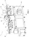
- At 1 is indicated collectively a machine for machining the underside of a ski according to the invention.
- the machine 1 comprises a grinding wheel 10 having a cylindrical side surface 12 that defines a grinding wheel rotation axis A.
- the grinding wheel 12 is placed in rotation about the rotation axis A by a first electric motor 14.
- the machine further comprises a grinding wheel machining tool 16, for example a diamond tool, suitable to be placed in contact with the rotating grinding wheel 10 so as to create grooves on the cylindrical side surface 12.
- a grinding wheel machining tool 16 for example a diamond tool
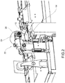
- Figure 3 illustrates the tool 16 and its related movement group.
- the tool 16 is moved by a second electric motor 18.
- the second electric motor 18 is suitable to translate the tool 16 along a longitudinal tool translation axis Y parallel to the grinding wheel rotation axis A.
- a third electric motor 20 is suitable to move the tool 16 along a transversal axis of penetration X, orthogonal to the grinding wheel rotation axis A;
- the machine 1 further comprises a ski pulling group 22 suitable to move the ski along a ski advancement axis Z, parallel to the direction of longitudinal extension of the ski.
- the ski pulling group 22 comprises a pulling wheel 24 facing the grinding wheel 10 and positionable above the ski on the side opposite the underside.
- the pulling wheel 24 is set in rotation by a fourth electric motor 26 so as to move the ski along the direction of advancement Z at a speed corresponding to the tangential speed of the pulling wheel 24.
- the pulling wheel 24 is made of a deformable material, for example rubber, and contains a pressurized fluid that determines the profile of the outer surface of the wheel 24 that comes in contact with the ski.
- the machine 1 is provided with means for adjusting the pressure of the pressurized fluid of the wheel 24, so as to modify, as will be described hereinafter, the profile of the outer surface of the wheel 24.
- the pulling group 22 further comprises an input roller group 28 and an output roller group 30.
- the processing unit 40 is programmed to generate multiprofile patterns, for example by the technique described in EP1179391A2 .
- the production of multiprofile patterns involves the creation of first threads, called “mother threads”, which develop along helical paths around the rotation axis A of the grinding wheel, and second threads, called “splitting threads”, which intersect with the mother threads.
- the mother threads and the splitting threads create a pattern of threads having predetermined pitches and steps, and which define between them tooth hobs on the lateral surface of the grinding wheel 10.
- these tooth hobs engage the underside of the ski and reproduce the micro-grooving of the corresponding design.
- the machining method of the underside of the ski provides for generating a profile from said pattern, i.e. a position, speed, and acceleration curve for controlling the first electric motor 14.
- This first electric motor 14 will be the "master" motor for controlling the other motors.
- an electronic cam is defined that links the position, speed and acceleration profile of each of the remaining electric motors to the position, speed and acceleration profile of the first electric motor 14.
- electro cam is used here according to the known definition of the prior art that deals with automation systems employing multiple electric motors that must be synchronized with each other, and which substantially designates a transmission function that describes the position, speed and acceleration profile of an electric motor (slave) as a function of the position, speed and acceleration profile of another electric motor (master).
- an electric motor (slave) follows the movement of another electric motor (master) according to a law established by the electronic cam.
- An electronic cam is usually described by a family of graphs, for example representative of the position, velocity and acceleration transmission function.
- the machine is able to convert positioning, speed and acceleration graphs of the electronic cams into a sequence of machine instructions that allow slave electric motors to follow the master electric motor 14 (the motor of the grinding wheel) with the desired precision.
- the dependence of the slave electric motors on the master motor of the grinding wheel is as follows:
- a pattern by combining multiple profile structures, i.e., a pattern wherein at least one second profile structure is embedded in a first profile structure without the second structure altering the function of the first structure.
- a first structure is selected corresponding to a first grooving adapted to form on the underside of the ski a plurality of first ridges 60 interposed by a plurality of first valleys 62.
- the operator further selects a second structure corresponding to a second groove 70 adapted to form on the underside of the ski a plurality of second ridges 72 interposed by a plurality of second valleys 74.
- the four electric motors are controlled in such a way as to produce the second grooving 70 on one or more of the first ridges 60 and/or in one or more of the first valleys 62 of the first grooving.
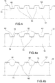
- Figure 4 schematically shows the lateral surface 12 of the grinding wheel 10, wherein the first grooving is carved to form ridges 60 and valleys 62 of a certain width and height, for example, 40 ⁇ m.
- a second grooving 70 with a much finer step than the first and having a height, for example of 20 ⁇ m, is made on both the ridges and the valleys of the first grooving.
- the second grooving 70 is made only in the valleys 62 of the first grooving.
- the second grooving 70 is made only on the ridges 60 of the first grooving.
- the valleys of the first grooving, lacking the second grooving may have a concave shape rather than flat.
- Figure 5 schematically shows a portion of the underside of a ski 80, wherein a pattern has been carved reflecting the carving of the grinding wheel shown in figure 4a .
- Grooves 82 are in fact highlighted which correspond to the first ridges 60, spaced by ridges 84, for example with a flat profile, corresponding to the first valleys 62.
- the second grooving 70 is engraved (complementarily) on each of such ridges 82.
- Such a shape of the pattern is particularly effective during alpine skiing competitions, where the snow temperature is so variable along the track that a single grooving on the underside of the ski suitable to make the ski glide on one stretch of the track would not be as effective on other sections with different snow temperatures.
- the different grooves created on different levels allow the maximum glide of the underside of the ski to always be obtained.
- the second grooving 70 made on the ridges of the first pattern is effective; on an end section of the track where the snow is wet, the valleys, or grooves, 82 of the first grooving are effective.
- the first three electric motors are controlled in such a way as to affect the lateral surface of the grinding wheel with a continuous action of the tool. Also, this method of carving of the grinding wheel, which requires very high precision in the control of the motors so that the second pattern does not damage the first pattern, is made possible by programming with electronic cams defined by polynomials.
- the pattern of multiple structures made on the lateral surface of the grinding wheel is transferred to the underside of the ski in a single pass of the ski on the machine. This results in a drastic reduction in machining time of the underside of the ski and prevents subsequent passes from altering the structure made with a first pass.
- the user interface permits, after selecting a type of pattern 50 to be carved on the underside of the ski, to select also at least one geometric characteristic of such pattern in a predetermined range of values.
- the value of the following characteristics of the pattern may be selected: angle of inclination of the splitting, length of the pattern, length of the distance between two consecutive patterns, depth of the pattern profile, step of the pattern profile, the number of mother-line profile threads, the number of threads of the splitting line profile.
- the processing unit recalculates the polynomials of the position, speed and acceleration curves of the first electric motor, and the polynomials of the electronic cams of the other electric motors.
- the user interface provides the operator with the possibility to create a new pattern with a simple drawing tool, for example, by modifying a base pattern as desired.
- the processing unit is programmed so as to break up the new pattern into portions of the pattern stored in the pattern database for which the control polynomials of the electric motors are already known.
- the database accessible from the processing unit contains an archive of "macros", each corresponding to a portion of the pattern, which may be combined to create endless patterns.
- the processing unit is moreover programmed to generate any connection portions between the portions of the pattern to be connected, for example by interpolation.
- the machine is equipped with sensors and transducers suitable to detect the current diameter of the grinding wheel, the geometrical characteristics of the tool, the pressure of the ski pulling wheel, and other quantities that may affect the machining on the underside of the ski.
- the angle of inclination of the splitting thread is calculated in real time during the carving of the side wall of the grinding wheel as a function of the diameter of the grinding wheel.
- the difference between the rotation speed of the grinding wheel during the creation of the mother thread and the rotation speed of the grinding wheel during the creation of the splitting thread is calculated in real time as a function of the diameter of the grinding wheel.
- the procedure for machining the underside of the ski also takes into account the size and shape of the ski, and, in particular, some parameters of the machining procedure vary according to the portion of the ski that is in contact with the grinding wheel.
- the values of the length and/or width of the front, center and rear portions of a ski to be subjected to machining on its underside are provided to the machine.
- the first electric motor 14 and/or the fourth electric motor 26 is controlled so as to vary its speed at the passage over the grinding wheel from one such portion of the ski to another. In this way, the number of patterns per unit length between one ski portion and another is differentiated.
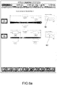
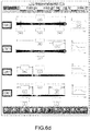
- Figures 6a and 6b show, for example, speed profiles 90, 90'; 92, 92' of the fourth and of the first motor for a ski for alpine skiing and a ski for cross-country skiing, respectively, as a function of the length of the skis and their portions.
- the pressure exerted by the pulling wheel 24 on the ski varies, both as a function of the current diameter of the grinding wheel, and as a function of the portion of the ski subjected to machining.
- This pressure is controlled either to dynamically correct the pressure value per unit of surface depending on the width of the ski in order to have constant pressure, or to reduce the pressure in the tail of the ski in order to avoid, especially with cross-country skis, excessive wear on the underside, as is apparent, for example, from the pressure curve 100 of figure 6c , relating to cross-country skiing.
- the profile of the pulling wheel in contact with the ski may also be modified according to the portion of the ski subjected to machining by controlling the pressure of the fluid present in the wheel. For example, one may go from a "saddle-shaped" profile that better distributes the pressure to the edges of the ski, to a concave profile, which concentrates the pressure on the central portion of the ski.
Landscapes
- Engineering & Computer Science (AREA)
- Mechanical Engineering (AREA)
- Grinding And Polishing Of Tertiary Curved Surfaces And Surfaces With Complex Shapes (AREA)
- Constituent Portions Of Griding Lathes, Driving, Sensing And Control (AREA)
Applications Claiming Priority (1)
| Application Number | Priority Date | Filing Date | Title |
|---|---|---|---|
| ITUA2016A004355A ITUA20164355A1 (it) | 2016-06-14 | 2016-06-14 | Metodo e macchina di lavorazione della soletta di uno sci |
Publications (1)
| Publication Number | Publication Date |
|---|---|
| EP3257628A1 true EP3257628A1 (en) | 2017-12-20 |
Family
ID=57184665
Family Applications (1)
| Application Number | Title | Priority Date | Filing Date |
|---|---|---|---|
| EP17175107.6A Withdrawn EP3257628A1 (en) | 2016-06-14 | 2017-06-08 | Method and machine for machining the underside of a ski |
Country Status (2)
| Country | Link |
|---|---|
| EP (1) | EP3257628A1 (it) |
| IT (1) | ITUA20164355A1 (it) |
Cited By (3)
| Publication number | Priority date | Publication date | Assignee | Title |
|---|---|---|---|---|
| IT201700051621A1 (it) * | 2017-05-12 | 2018-11-12 | Svecom P E S R L | Un impianto di lavorazione della superficie di scivolamento di uno sci |
| CN113144573A (zh) * | 2021-05-17 | 2021-07-23 | 上海诺倬力机电科技有限公司 | 滑雪板磨床系统 |
| DE102023109813B3 (de) | 2023-04-19 | 2024-08-29 | Marco Luck | Vorrichtung zur Bearbeitung von Ski |
Citations (6)
| Publication number | Priority date | Publication date | Assignee | Title |
|---|---|---|---|---|
| DE4033235A1 (de) * | 1989-11-02 | 1991-05-08 | Fischer Gmbh | Ski |
| EP1179391A2 (en) | 2000-08-04 | 2002-02-13 | Giuseppe Moroni | Procedure for creating multi-thread forms on a grindstone, particularly for the micro-scoring of the underside of skis |
| DE10130392A1 (de) * | 2001-06-23 | 2003-01-09 | Bernd Spaeth | Vorrichtung und Geräte, insbesondere Gleitelemente, beispielweise Schneegleitelemente, mit verbesserten Eigenschaften |
| US20110275291A1 (en) * | 2009-02-13 | 2011-11-10 | Svein Iversbakken | Device for grinding of ski soles |
| DE102012018894A1 (de) * | 2011-10-06 | 2013-04-11 | Ernst Knoll Feinmechanik Gmbh | Vorrichtung zum Konditionieren der Lauffläche zumindest eines brettförmigen Wintersportgerätes sowie Verfahren unter Verwendung einer solchen Vorrichtung |
| US20140088767A1 (en) * | 2011-03-15 | 2014-03-27 | Omron Corporation | Computation unit, output control method, and program |
-
2016
- 2016-06-14 IT ITUA2016A004355A patent/ITUA20164355A1/it unknown
-
2017
- 2017-06-08 EP EP17175107.6A patent/EP3257628A1/en not_active Withdrawn
Patent Citations (6)
| Publication number | Priority date | Publication date | Assignee | Title |
|---|---|---|---|---|
| DE4033235A1 (de) * | 1989-11-02 | 1991-05-08 | Fischer Gmbh | Ski |
| EP1179391A2 (en) | 2000-08-04 | 2002-02-13 | Giuseppe Moroni | Procedure for creating multi-thread forms on a grindstone, particularly for the micro-scoring of the underside of skis |
| DE10130392A1 (de) * | 2001-06-23 | 2003-01-09 | Bernd Spaeth | Vorrichtung und Geräte, insbesondere Gleitelemente, beispielweise Schneegleitelemente, mit verbesserten Eigenschaften |
| US20110275291A1 (en) * | 2009-02-13 | 2011-11-10 | Svein Iversbakken | Device for grinding of ski soles |
| US20140088767A1 (en) * | 2011-03-15 | 2014-03-27 | Omron Corporation | Computation unit, output control method, and program |
| DE102012018894A1 (de) * | 2011-10-06 | 2013-04-11 | Ernst Knoll Feinmechanik Gmbh | Vorrichtung zum Konditionieren der Lauffläche zumindest eines brettförmigen Wintersportgerätes sowie Verfahren unter Verwendung einer solchen Vorrichtung |
Cited By (4)
| Publication number | Priority date | Publication date | Assignee | Title |
|---|---|---|---|---|
| IT201700051621A1 (it) * | 2017-05-12 | 2018-11-12 | Svecom P E S R L | Un impianto di lavorazione della superficie di scivolamento di uno sci |
| EP3412346A1 (en) * | 2017-05-12 | 2018-12-12 | Svecom - P.E. S.R.L. | A working plant of a sliding surface of a ski |
| CN113144573A (zh) * | 2021-05-17 | 2021-07-23 | 上海诺倬力机电科技有限公司 | 滑雪板磨床系统 |
| DE102023109813B3 (de) | 2023-04-19 | 2024-08-29 | Marco Luck | Vorrichtung zur Bearbeitung von Ski |
Also Published As
| Publication number | Publication date |
|---|---|
| ITUA20164355A1 (it) | 2017-12-14 |
Similar Documents
| Publication | Publication Date | Title |
|---|---|---|
| EP3257628A1 (en) | Method and machine for machining the underside of a ski | |
| US6491482B1 (en) | Milling method | |
| EP2576136B1 (en) | Adaptive control of a machining process | |
| KR101859651B1 (ko) | 기어 톱니의 창성 방법 및 상기 방법을 이용하여 작동될 수 있는 기어 절삭기 | |
| WO2018146018A3 (de) | Verfahren und steuervorrichtung zur bearbeitung einer werkstückoberfläche mittels eines lasers | |
| CN102416507B (zh) | 有人字形齿的齿轮制备方法及生成控制数据的方法和装置 | |
| CN110121393B (zh) | 对内部齿形部分硬表面加工的方法和适合该方法的机床 | |
| JP5746270B2 (ja) | 穴あけ加工を行う工作機械の数値制御装置 | |
| CN108381308A (zh) | 切齿刀具的加工装置及方法、工具形状模拟装置及方法 | |
| CN103042469A (zh) | 用于修整多线磨削螺杆和用于磨削的方法及磨削螺杆 | |
| CN105689807A (zh) | 具有多个切削策略的强力刮削加工方法 | |
| EP1683597B1 (en) | Method of processing a semi-finished product for the production of a rotor with integral blades | |
| JP2010076032A (ja) | テーパホーニング加工方法およびテーパホーニング盤 | |
| CA2316898C (en) | Hobble turning method and preferred application for said method | |
| EP3275512A1 (en) | Method and system for machining a ski | |
| JP3689367B2 (ja) | ホブカッター及びフェースギア形成方法 | |
| KR102930274B1 (ko) | 공작물 상의 톱니부를 기계가공 및 생성하는 방법 | |
| DE69308937T2 (de) | Verfahren und Vorrichtung zum Abschneiden einer Halbleiterscheibe | |
| FI67485C (fi) | Skida | |
| WO2013156837A1 (en) | Ski, grinding wheel for machining said ski and machine comprising said grinding wheel | |
| US3130481A (en) | Method of manufacturing a blade wheel | |
| US3220032A (en) | Thread cutting tap | |
| US6416383B1 (en) | Device for dressing a grindstone to polish the running surface structure of a ski | |
| US2421490A (en) | Metal removing tool | |
| EP1179391B1 (en) | Procedure for creating multi-thread forms on a grindstone, particularly for the micro-scoring of the underside of skis |
Legal Events
| Date | Code | Title | Description |
|---|---|---|---|
| PUAI | Public reference made under article 153(3) epc to a published international application that has entered the european phase |
Free format text: ORIGINAL CODE: 0009012 |
|
| AK | Designated contracting states |
Kind code of ref document: A1 Designated state(s): AL AT BE BG CH CY CZ DE DK EE ES FI FR GB GR HR HU IE IS IT LI LT LU LV MC MK MT NL NO PL PT RO RS SE SI SK SM TR |
|
| AX | Request for extension of the european patent |
Extension state: BA ME |
|
| STAA | Information on the status of an ep patent application or granted ep patent |
Free format text: STATUS: THE APPLICATION IS DEEMED TO BE WITHDRAWN |
|
| 18D | Application deemed to be withdrawn |
Effective date: 20180621 |