EP3257631A1 - Spannvorrichtung und verfahren zum spannen eines werkstücks - Google Patents
Spannvorrichtung und verfahren zum spannen eines werkstücks Download PDFInfo
- Publication number
- EP3257631A1 EP3257631A1 EP17171939.6A EP17171939A EP3257631A1 EP 3257631 A1 EP3257631 A1 EP 3257631A1 EP 17171939 A EP17171939 A EP 17171939A EP 3257631 A1 EP3257631 A1 EP 3257631A1
- Authority
- EP
- European Patent Office
- Prior art keywords
- piston
- workpiece
- puller member
- sensor
- tensioning device
- Prior art date
- Legal status (The legal status is an assumption and is not a legal conclusion. Google has not performed a legal analysis and makes no representation as to the accuracy of the status listed.)
- Withdrawn
Links
Images



Classifications
-
- B—PERFORMING OPERATIONS; TRANSPORTING
- B25—HAND TOOLS; PORTABLE POWER-DRIVEN TOOLS; MANIPULATORS
- B25B—TOOLS OR BENCH DEVICES NOT OTHERWISE PROVIDED FOR, FOR FASTENING, CONNECTING, DISENGAGING, OR HOLDING
- B25B29/00—Accessories
- B25B29/02—Bolt tensioners
-
- B—PERFORMING OPERATIONS; TRANSPORTING
- B25—HAND TOOLS; PORTABLE POWER-DRIVEN TOOLS; MANIPULATORS
- B25B—TOOLS OR BENCH DEVICES NOT OTHERWISE PROVIDED FOR, FOR FASTENING, CONNECTING, DISENGAGING, OR HOLDING
- B25B29/00—Accessories
Definitions
- Tensioning systems apply tension to one or more bolts to ensure a predetermined clamping force across a joint. Tensioning systems apply an axially load to each bolt (or bolts) to preload the bolt. Mechanical force is applied in an axial direction rather than by applying torque, thereby eliminating inaccuracies caused by friction between a nut and a seating surface.
- a tensioning device for tensioning a workpiece includes a main body having a chamber, a fluid inlet providing fluid communication between a fluid source and the chamber, a puller member supported in the main body and configured to engage the workpiece, and a piston positioned in the chamber and coupled to the puller member. Movement of the piston moves the puller member along a piston axis in at least a first direction.
- the tensioning device further includes a sensor coupled to the piston and operative to measure a displacement of at least one of the piston and the puller member in a direction parallel to the piston axis. The sensor generates a signal indicative of the displacement.
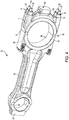
- a connecting rod 23 includes a main arm 50 and a cap portion 59 removably coupled to the main arm 50.
- the main arm 50 includes a first end 53 and a second end 56.
- the connecting rod 23 defines a first bearing aperture 62 proximate the first end 53 and a second bearing aperture 65 formed when the cap portion 59 is connected to the main arm 50 proximate the second end 56.
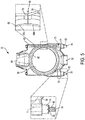
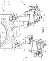
- Bolts 26 extend through respective apertures 68 in a flange or shoulder of the second end 56 of the main arm 50, and each bolt 26 also extends through a respective aperture 71 of the cap portion 59 when the cap portion 59 is coupled to the main arm 50. Although one aperture 68 and one aperture 71 is shown in FIG. 4 , it is understood that each of the illustrated bolts 26 extends through similar apertures 68 and 71.
- the connecting rod 23 further includes a plurality of nuts 74 that engage the bolts 26 to removably secure the cap portion 59 to the main arm 50.
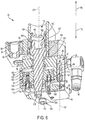
- each nut 74 includes an internal threaded region 77 ( FIG. 8 ) that threadably engages a corresponding external threaded region 80 of each bolt 26, as shown in FIG. 5 .
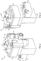
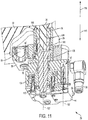
- the cylinder assembly 32 includes a chamber 98 that receives pressurized fluid from the pump system 10 ( FIG. 1 ) via the fluid inlet 38.
- the cylinder assembly 32 further includes seals 101 to inhibit pressurized fluid from leaking out of the chamber 98, and a piston 104 that moves along a piston axis 107 relative to the main body 29.
- the piston 104 moves in response to a force differential between sides 102, 103 of the piston 104.
- a first side 102 of the piston 104 is subjected to a force caused by pressurized fluid entering the chamber 98, biasing the piston 104 in a first direction 110.
- the visual indicator 143 is a line that becomes visible when the piston 104 nears the predetermined stroke length (e.g., 8.5 mm) and provides a visual warning to the operator that the relief valve 119 will release pressure from the chamber 98.
- a collar 146 is positioned around the pulling member 125 and is disposed between the ends 134, 140. The piston 104 abuts the collar 146 of the pulling member 125 when the piston 104 moves in direction 110, thereby forcing the pulling member 125 to move along the piston axis 107.
- each hydraulic tensioner 20 moves in direction 110 (e.g., due to gravity) so that the drive socket ends 134 extend beyond the main body 29 of each hydraulic tensioner 20.
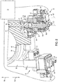
- a tool (not shown) is individually inserted into the socket drive 131 of each pulling member 125 to rotate each pulling member 125 about its respective piston axis 107, thereby threading the threaded aperture 137 ( FIG. 6 ) of each pulling member 125 onto the external threaded region 80 of each bolt 26.
- Each pulling member 125 is threadably secured to an associated bolt 26, as illustrated in FIG. 8 .
- the piston 104 abuts the collar 146 of the pulling member 125, thereby driving the pulling member 125 in direction 110 along the piston axis 107 as well.
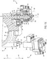
- the pulling member 125 applies tension to the bolt 26.
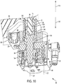
- a gap or space 166 (only one of which is shown in FIG. 10 ) is formed between the nut 74 and the cap portion 59 of the connecting rod 23.
- the sensor 47 detects the displacement of the piston 104.
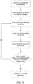
- the sensor 47 generates and transmits a signal to the controller 169 ( FIG.
- the initial pressurization shown in FIG. 10 corresponds to an initial pull that is applied to achieve the bearing crush or compaction. Once this is done, additional pressure is applied to the piston 104 to achieve a desired tensile load in the bolts 26.
- the amount of torque required to thread the nut 74 in direction 116 is relatively small because the nut 74 rotates freely along the bolts 26 when the space 166 is present. Furthermore, due to the space 166 between the nut 74 and the cap portion 59, there is little friction generated at the interface between the nut 74 and the cap portion 59.
Landscapes
- Engineering & Computer Science (AREA)
- Mechanical Engineering (AREA)
- Hand Tools For Fitting Together And Separating, Or Other Hand Tools (AREA)
Applications Claiming Priority (1)
| Application Number | Priority Date | Filing Date | Title |
|---|---|---|---|
| US201662338873P | 2016-05-19 | 2016-05-19 |
Publications (1)
| Publication Number | Publication Date |
|---|---|
| EP3257631A1 true EP3257631A1 (de) | 2017-12-20 |
Family
ID=58772710
Family Applications (1)
| Application Number | Title | Priority Date | Filing Date |
|---|---|---|---|
| EP17171939.6A Withdrawn EP3257631A1 (de) | 2016-05-19 | 2017-05-19 | Spannvorrichtung und verfahren zum spannen eines werkstücks |
Country Status (2)
| Country | Link |
|---|---|
| US (1) | US10800020B2 (de) |
| EP (1) | EP3257631A1 (de) |
Families Citing this family (6)
| Publication number | Priority date | Publication date | Assignee | Title |
|---|---|---|---|---|
| GB2579661A (en) * | 2018-12-11 | 2020-07-01 | Tentec Ltd | Hydraulic tensioning apparatus |
| USD995253S1 (en) | 2019-09-26 | 2023-08-15 | Enerpac Tool Group Corp. | Tensioning device |
| WO2021062224A1 (en) | 2019-09-26 | 2021-04-01 | Enerpac Tool Group Corp. | Tensioning device |
| GB202017991D0 (en) * | 2020-11-16 | 2020-12-30 | Acutension Ltd | Improved bolt tensioner |
| USD1125286S1 (en) * | 2021-07-12 | 2026-05-05 | Atlas Copco Industrial Technique Ab | Bolt tensioner |
| US12305527B1 (en) * | 2023-11-16 | 2025-05-20 | Rtx Corporation | Method and system for applying pre-stretch to shaft and component connection |
Citations (11)
| Publication number | Priority date | Publication date | Assignee | Title |
|---|---|---|---|---|
| WO1986005135A1 (en) * | 1985-03-06 | 1986-09-12 | Pilgrim Engineering Developments Limited | Improvements in multi-stud tensioners |
| US4829650A (en) * | 1985-11-21 | 1989-05-16 | Eg&G Sealol | Method and apparatus for tightening and/or slackening bolts |
| US5257207A (en) * | 1989-07-14 | 1993-10-26 | Warren Richard P | Method for monitoring gasket compression during fastener tensioning |
| US20080173140A1 (en) * | 2005-04-06 | 2008-07-24 | Jorg Hohmann | Hydraulic Threaded Bolt Clamping Device and Method For Tightening Large Screws by Means of Said Hydraulic Threaded Bolt Clamping Device |
| US8261421B2 (en) * | 2006-09-01 | 2012-09-11 | Aktiebolaget Skf | Method for setting up and controlling a hydraulic tensioner for applying a preload on one or a plurality of bolts |
| EP2522465A1 (de) * | 2011-05-13 | 2012-11-14 | AMTEC Advanced Measurement Messtechnischer Service GmbH | Vorrichtung zum kontrollierten Verspannen von Flanschverbindungen |
| EP2671673A1 (de) * | 2011-02-01 | 2013-12-11 | Mitsubishi Heavy Industries, Ltd. | Befestigungs- und ablösungsvorrichtung |
| US20140165789A1 (en) * | 2012-09-18 | 2014-06-19 | Jörg Hohmann | Tensioning device for extending a threaded bolt, and tool suitable for this purpose, preferably drive adapter |
| WO2015118283A1 (en) * | 2014-02-06 | 2015-08-13 | Tentec Limited | Tensioner |
| WO2015152728A1 (en) * | 2014-04-04 | 2015-10-08 | Hytorc Norge As | Interface device for tensioning a nut and a bolt assembly |
| US9248532B2 (en) * | 2008-11-14 | 2016-02-02 | Wagner Vermoegensverwaltungs-Gmbh & Co. Kg | Screw tensioning device |
Family Cites Families (6)
| Publication number | Priority date | Publication date | Assignee | Title |
|---|---|---|---|---|
| US3844533A (en) * | 1973-03-12 | 1974-10-29 | Transfer Systems | Automatic stud tensioner |
| GB8823474D0 (en) * | 1988-10-06 | 1988-11-16 | Hedley Purvis Ltd | Improved hydraulic tensioner |
| DE4313778A1 (de) * | 1993-04-27 | 1994-11-03 | Westfalia Becorit Ind Tech | Schraubenspannvorrichtung |
| US7331255B2 (en) * | 2001-09-21 | 2008-02-19 | Petrak Gregory H | Method and apparatus for tensioning an emergency brake system on a vehicle |
| DE102012106503B4 (de) * | 2012-07-18 | 2023-03-16 | Jörg Hohmann | Spannvorrichtung zum Dehnen eines Gewindebolzens |
| DE102014106215A1 (de) * | 2014-05-05 | 2015-11-05 | Frank Hohmann | Spannvorrichtung zum Dehnen eines Gewindebolzens |
-
2017
- 2017-05-19 EP EP17171939.6A patent/EP3257631A1/de not_active Withdrawn
- 2017-05-19 US US15/599,591 patent/US10800020B2/en active Active
Patent Citations (11)
| Publication number | Priority date | Publication date | Assignee | Title |
|---|---|---|---|---|
| WO1986005135A1 (en) * | 1985-03-06 | 1986-09-12 | Pilgrim Engineering Developments Limited | Improvements in multi-stud tensioners |
| US4829650A (en) * | 1985-11-21 | 1989-05-16 | Eg&G Sealol | Method and apparatus for tightening and/or slackening bolts |
| US5257207A (en) * | 1989-07-14 | 1993-10-26 | Warren Richard P | Method for monitoring gasket compression during fastener tensioning |
| US20080173140A1 (en) * | 2005-04-06 | 2008-07-24 | Jorg Hohmann | Hydraulic Threaded Bolt Clamping Device and Method For Tightening Large Screws by Means of Said Hydraulic Threaded Bolt Clamping Device |
| US8261421B2 (en) * | 2006-09-01 | 2012-09-11 | Aktiebolaget Skf | Method for setting up and controlling a hydraulic tensioner for applying a preload on one or a plurality of bolts |
| US9248532B2 (en) * | 2008-11-14 | 2016-02-02 | Wagner Vermoegensverwaltungs-Gmbh & Co. Kg | Screw tensioning device |
| EP2671673A1 (de) * | 2011-02-01 | 2013-12-11 | Mitsubishi Heavy Industries, Ltd. | Befestigungs- und ablösungsvorrichtung |
| EP2522465A1 (de) * | 2011-05-13 | 2012-11-14 | AMTEC Advanced Measurement Messtechnischer Service GmbH | Vorrichtung zum kontrollierten Verspannen von Flanschverbindungen |
| US20140165789A1 (en) * | 2012-09-18 | 2014-06-19 | Jörg Hohmann | Tensioning device for extending a threaded bolt, and tool suitable for this purpose, preferably drive adapter |
| WO2015118283A1 (en) * | 2014-02-06 | 2015-08-13 | Tentec Limited | Tensioner |
| WO2015152728A1 (en) * | 2014-04-04 | 2015-10-08 | Hytorc Norge As | Interface device for tensioning a nut and a bolt assembly |
Also Published As
| Publication number | Publication date |
|---|---|
| US10800020B2 (en) | 2020-10-13 |
| US20170334049A1 (en) | 2017-11-23 |
Similar Documents
| Publication | Publication Date | Title |
|---|---|---|
| US10800020B2 (en) | Tensioning device and method for tensioning a workpiece | |
| US9415557B2 (en) | Electric cylinder system | |
| CN103323232B (zh) | 风力发电机联轴器打滑力矩标定试验台及标定方法 | |
| US20140245868A1 (en) | Screw tensioning device | |
| CN201836038U (zh) | 一种隔膜泵的十字头与活塞杆的连接装置 | |
| JP6996891B2 (ja) | ねじボルトを延伸させる締付け装置 | |
| JP4856696B2 (ja) | 油圧ねじボルト締め付け装置および該装置により大型スクリューを締め付ける方法。 | |
| US9623524B2 (en) | Tensioning device for expanding a threaded bolt | |
| US9505106B2 (en) | Method for rotating a rotatable part | |
| CN101943576A (zh) | 工程机械转向角度检测装置 | |
| CN204405438U (zh) | 一种软轴拉伸测试实验台 | |
| EP2880318B1 (de) | Pumpe mit automatischem zyklus und betriebsverfahren dafür | |
| EP2436936B1 (de) | System zur Prüfung der Schraubenvorspannung | |
| US12246418B2 (en) | Load measurement system for hydraulic torque wrench | |
| CN112584977B (zh) | 用于拧紧螺栓上的螺母以形成固定连接的工具 | |
| US20090218835A1 (en) | System for positioning an operating cylinder, use of the system, and machine | |
| KR20120055257A (ko) | 대형 볼트 유압 자동 체결 장치 | |
| CN103758816B (zh) | 可调行程集成串联缸 | |
| KR20160064636A (ko) | 체결형 볼트의 풀림특성 검출장치 | |
| CN107605863A (zh) | 一种电缆摆动测试装置 | |
| CN107063531A (zh) | 用于确定转矩的方法和设备以及驱动单元 | |
| CN102985225B (zh) | 用于操作扭矩扳手或类似装置的电路布置 | |
| KR101724329B1 (ko) | 작동기의 백래시 및 강성 측정 장치 | |
| WO2012114361A1 (en) | Hydraulic spanner | |
| EP2644948A3 (de) | Vorrichtung und Verfahren zur Steuerung des Hydraulikflüssigkeitdruckspeisungs eines Arbeitsfahrzeuggetriebes |
Legal Events
| Date | Code | Title | Description |
|---|---|---|---|
| PUAI | Public reference made under article 153(3) epc to a published international application that has entered the european phase |
Free format text: ORIGINAL CODE: 0009012 |
|
| AK | Designated contracting states |
Kind code of ref document: A1 Designated state(s): AL AT BE BG CH CY CZ DE DK EE ES FI FR GB GR HR HU IE IS IT LI LT LU LV MC MK MT NL NO PL PT RO RS SE SI SK SM TR |
|
| AX | Request for extension of the european patent |
Extension state: BA ME |
|
| 17P | Request for examination filed |
Effective date: 20180613 |
|
| RBV | Designated contracting states (corrected) |
Designated state(s): AL AT BE BG CH CY CZ DE DK EE ES FI FR GB GR HR HU IE IS IT LI LT LU LV MC MK MT NL NO PL PT RO RS SE SI SK SM TR |
|
| 17Q | First examination report despatched |
Effective date: 20190604 |
|
| RAP1 | Party data changed (applicant data changed or rights of an application transferred) |
Owner name: ENERPAC TOOL GROUP CORP. |
|
| STAA | Information on the status of an ep patent application or granted ep patent |
Free format text: STATUS: THE APPLICATION IS DEEMED TO BE WITHDRAWN |
|
| 18D | Application deemed to be withdrawn |
Effective date: 20200926 |