EP3257647A1 - Härtungswerkzeug - Google Patents
Härtungswerkzeug Download PDFInfo
- Publication number
- EP3257647A1 EP3257647A1 EP17175766.9A EP17175766A EP3257647A1 EP 3257647 A1 EP3257647 A1 EP 3257647A1 EP 17175766 A EP17175766 A EP 17175766A EP 3257647 A1 EP3257647 A1 EP 3257647A1
- Authority
- EP
- European Patent Office
- Prior art keywords
- reflector
- tool
- light
- tool according
- leds
- Prior art date
- Legal status (The legal status is an assumption and is not a legal conclusion. Google has not performed a legal analysis and makes no representation as to the accuracy of the status listed.)
- Withdrawn
Links
Images
Classifications
-
- B—PERFORMING OPERATIONS; TRANSPORTING
- B29—WORKING OF PLASTICS; WORKING OF SUBSTANCES IN A PLASTIC STATE IN GENERAL
- B29C—SHAPING OR JOINING OF PLASTICS; SHAPING OF MATERIAL IN A PLASTIC STATE, NOT OTHERWISE PROVIDED FOR; AFTER-TREATMENT OF THE SHAPED PRODUCTS, e.g. REPAIRING
- B29C35/00—Heating, cooling or curing, e.g. crosslinking or vulcanising; Apparatus therefor
- B29C35/02—Heating or curing, e.g. crosslinking or vulcanizing during moulding, e.g. in a mould
- B29C35/08—Heating or curing, e.g. crosslinking or vulcanizing during moulding, e.g. in a mould by wave energy or particle radiation
-
- B—PERFORMING OPERATIONS; TRANSPORTING
- B29—WORKING OF PLASTICS; WORKING OF SUBSTANCES IN A PLASTIC STATE IN GENERAL
- B29C—SHAPING OR JOINING OF PLASTICS; SHAPING OF MATERIAL IN A PLASTIC STATE, NOT OTHERWISE PROVIDED FOR; AFTER-TREATMENT OF THE SHAPED PRODUCTS, e.g. REPAIRING
- B29C35/00—Heating, cooling or curing, e.g. crosslinking or vulcanising; Apparatus therefor
- B29C35/02—Heating or curing, e.g. crosslinking or vulcanizing during moulding, e.g. in a mould
- B29C35/08—Heating or curing, e.g. crosslinking or vulcanizing during moulding, e.g. in a mould by wave energy or particle radiation
- B29C35/0805—Heating or curing, e.g. crosslinking or vulcanizing during moulding, e.g. in a mould by wave energy or particle radiation using electromagnetic radiation
-
- B—PERFORMING OPERATIONS; TRANSPORTING
- B29—WORKING OF PLASTICS; WORKING OF SUBSTANCES IN A PLASTIC STATE IN GENERAL
- B29C—SHAPING OR JOINING OF PLASTICS; SHAPING OF MATERIAL IN A PLASTIC STATE, NOT OTHERWISE PROVIDED FOR; AFTER-TREATMENT OF THE SHAPED PRODUCTS, e.g. REPAIRING
- B29C35/00—Heating, cooling or curing, e.g. crosslinking or vulcanising; Apparatus therefor
- B29C35/02—Heating or curing, e.g. crosslinking or vulcanizing during moulding, e.g. in a mould
- B29C35/0266—Local curing
-
- B—PERFORMING OPERATIONS; TRANSPORTING
- B29—WORKING OF PLASTICS; WORKING OF SUBSTANCES IN A PLASTIC STATE IN GENERAL
- B29C—SHAPING OR JOINING OF PLASTICS; SHAPING OF MATERIAL IN A PLASTIC STATE, NOT OTHERWISE PROVIDED FOR; AFTER-TREATMENT OF THE SHAPED PRODUCTS, e.g. REPAIRING
- B29C71/00—After-treatment of articles without altering their shape; Apparatus therefor
- B29C71/04—After-treatment of articles without altering their shape; Apparatus therefor by wave energy or particle radiation, e.g. for curing or vulcanising preformed articles
-
- F—MECHANICAL ENGINEERING; LIGHTING; HEATING; WEAPONS; BLASTING
- F16—ENGINEERING ELEMENTS AND UNITS; GENERAL MEASURES FOR PRODUCING AND MAINTAINING EFFECTIVE FUNCTIONING OF MACHINES OR INSTALLATIONS; THERMAL INSULATION IN GENERAL
- F16L—PIPES; JOINTS OR FITTINGS FOR PIPES; SUPPORTS FOR PIPES, CABLES OR PROTECTIVE TUBING; MEANS FOR THERMAL INSULATION IN GENERAL
- F16L55/00—Devices or appurtenances for use in, or in connection with, pipes or pipe systems
- F16L55/18—Appliances for use in repairing pipes
-
- F—MECHANICAL ENGINEERING; LIGHTING; HEATING; WEAPONS; BLASTING
- F16—ENGINEERING ELEMENTS AND UNITS; GENERAL MEASURES FOR PRODUCING AND MAINTAINING EFFECTIVE FUNCTIONING OF MACHINES OR INSTALLATIONS; THERMAL INSULATION IN GENERAL
- F16L—PIPES; JOINTS OR FITTINGS FOR PIPES; SUPPORTS FOR PIPES, CABLES OR PROTECTIVE TUBING; MEANS FOR THERMAL INSULATION IN GENERAL
- F16L55/00—Devices or appurtenances for use in, or in connection with, pipes or pipe systems
- F16L55/26—Pigs or moles, i.e. devices movable in a pipe or conduit with or without self-contained propulsion means
-
- G—PHYSICS
- G21—NUCLEAR PHYSICS; NUCLEAR ENGINEERING
- G21K—HANDLING OF PARTICLES OR IONISING RADIATION NOT OTHERWISE PROVIDED FOR; IRRADIATION DEVICES; GAMMA RAY OR X-RAY MICROSCOPES
- G21K5/00—Irradiation devices
- G21K5/10—Irradiation devices with provision for relative movement of beam source and object to be irradiated
-
- H—ELECTRICITY
- H05—ELECTRIC TECHNIQUES NOT OTHERWISE PROVIDED FOR
- H05B—ELECTRIC HEATING; ELECTRIC LIGHT SOURCES NOT OTHERWISE PROVIDED FOR; CIRCUIT ARRANGEMENTS FOR ELECTRIC LIGHT SOURCES, IN GENERAL
- H05B3/00—Ohmic-resistance heating
- H05B3/0033—Heating devices using lamps
- H05B3/0038—Heating devices using lamps for industrial applications
- H05B3/0057—Heating devices using lamps for industrial applications for plastic handling and treatment
-
- B—PERFORMING OPERATIONS; TRANSPORTING
- B29—WORKING OF PLASTICS; WORKING OF SUBSTANCES IN A PLASTIC STATE IN GENERAL
- B29C—SHAPING OR JOINING OF PLASTICS; SHAPING OF MATERIAL IN A PLASTIC STATE, NOT OTHERWISE PROVIDED FOR; AFTER-TREATMENT OF THE SHAPED PRODUCTS, e.g. REPAIRING
- B29C35/00—Heating, cooling or curing, e.g. crosslinking or vulcanising; Apparatus therefor
- B29C35/02—Heating or curing, e.g. crosslinking or vulcanizing during moulding, e.g. in a mould
- B29C35/08—Heating or curing, e.g. crosslinking or vulcanizing during moulding, e.g. in a mould by wave energy or particle radiation
- B29C35/0805—Heating or curing, e.g. crosslinking or vulcanizing during moulding, e.g. in a mould by wave energy or particle radiation using electromagnetic radiation
- B29C2035/0822—Heating or curing, e.g. crosslinking or vulcanizing during moulding, e.g. in a mould by wave energy or particle radiation using electromagnetic radiation using IR radiation
-
- B—PERFORMING OPERATIONS; TRANSPORTING
- B29—WORKING OF PLASTICS; WORKING OF SUBSTANCES IN A PLASTIC STATE IN GENERAL
- B29C—SHAPING OR JOINING OF PLASTICS; SHAPING OF MATERIAL IN A PLASTIC STATE, NOT OTHERWISE PROVIDED FOR; AFTER-TREATMENT OF THE SHAPED PRODUCTS, e.g. REPAIRING
- B29C35/00—Heating, cooling or curing, e.g. crosslinking or vulcanising; Apparatus therefor
- B29C35/02—Heating or curing, e.g. crosslinking or vulcanizing during moulding, e.g. in a mould
- B29C35/08—Heating or curing, e.g. crosslinking or vulcanizing during moulding, e.g. in a mould by wave energy or particle radiation
- B29C35/0805—Heating or curing, e.g. crosslinking or vulcanizing during moulding, e.g. in a mould by wave energy or particle radiation using electromagnetic radiation
- B29C2035/0827—Heating or curing, e.g. crosslinking or vulcanizing during moulding, e.g. in a mould by wave energy or particle radiation using electromagnetic radiation using UV radiation
-
- B—PERFORMING OPERATIONS; TRANSPORTING
- B29—WORKING OF PLASTICS; WORKING OF SUBSTANCES IN A PLASTIC STATE IN GENERAL
- B29C—SHAPING OR JOINING OF PLASTICS; SHAPING OF MATERIAL IN A PLASTIC STATE, NOT OTHERWISE PROVIDED FOR; AFTER-TREATMENT OF THE SHAPED PRODUCTS, e.g. REPAIRING
- B29C35/00—Heating, cooling or curing, e.g. crosslinking or vulcanising; Apparatus therefor
- B29C35/02—Heating or curing, e.g. crosslinking or vulcanizing during moulding, e.g. in a mould
- B29C35/08—Heating or curing, e.g. crosslinking or vulcanizing during moulding, e.g. in a mould by wave energy or particle radiation
- B29C35/0805—Heating or curing, e.g. crosslinking or vulcanizing during moulding, e.g. in a mould by wave energy or particle radiation using electromagnetic radiation
- B29C2035/0833—Heating or curing, e.g. crosslinking or vulcanizing during moulding, e.g. in a mould by wave energy or particle radiation using electromagnetic radiation using actinic light
-
- B—PERFORMING OPERATIONS; TRANSPORTING
- B29—WORKING OF PLASTICS; WORKING OF SUBSTANCES IN A PLASTIC STATE IN GENERAL
- B29L—INDEXING SCHEME ASSOCIATED WITH SUBCLASS B29C, RELATING TO PARTICULAR ARTICLES
- B29L2023/00—Tubular articles
- B29L2023/22—Tubes or pipes, i.e. rigid
Definitions
- This invention relates to a curing tool, and in particular to a curing tool by which a material may be cured by exposure of the material to electromagnetic radiation of a predetermined wavelength or wavelength range.
- the invention relates to a tool whereby materials applied to the inner surface of an item may be cured.
- a number of curing devices are known and are in widespread use, for example for use in the curing of resins, printing inks and a number of other materials.
- the devices typically operate by being arranged to emit electromagnetic radiation of a predetermined wavelength or wavelength range towards to the material to be cured. Commonly, light in the ultra violet wavelength range is used. However, depending upon the material to be cured, other wavelengths may be employed. By way of example, visible light, infrared or near infrared light may be used.
- One application in which it is desired to be able to cure a material in a convenient manner is in the relining of underground pipes.
- a pipe requires relining, for example to reduce leakage therefrom, then it is known to push or pull a tool through the pipe that operates to spray or otherwise apply a suitable resin material to the inner surface of the wall of the pipe, or a pre-coated liner sleeve may be inserted within the pipe. Subsequently, a device is pulled or pushed through the pipe to irradiate the material to cure the material.
- the application of the resin and the curing function may, if desired, be undertaken by a single tool.
- EP2129956 describes a device that may be employed in the curing of the material. It comprises a body of generally cylindrical form, the outer peripheral surface of which is provided with an array of LEDs operable to emit ultra violet light in a radial direction to irradiate the material and thereby achieve curing.
- a curing tool comprising a tool body having an end wall generally perpendicular to an axis of the tool body, the tool being arranged to be moved, in use, in substantially the direction of the axis, an array of LEDs carried by the tool body, the LEDs being arranged to emit light in a direction generally parallel to the axis, and a reflector carried by the tool body and arranged to reflect light emitted from the LEDs and incident upon the reflector such that the reflected light is reflected in a direction generally perpendicular to the axis.
- the LEDs of the array may each emit light over a range of angles, and hence at least some of the light emitted from the LEDs may be emitted in a direction not truly parallel to the axis. Likewise, at least some of the light reflected from the reflector may not be truly perpendicular to the axis.
- the expressions 'generally parallel' and 'generally perpendicular' should be interpreted accordingly herein.
- the reflector may be fixed relative to the body.
- it may be of generally conical form. If desired, it may be geometrically shaped to focus the reflected light, for example having a reflective peripheral surface of generally parabolic conical form.
- the reflector may be movably mounted, for example being arranged to rotate about the axis, such that the reflected light is scanned around the tool as the reflector rotates.
- the tool may further comprise a window through which the reflected light is transmitted.
- a window through which the reflected light is transmitted.
- a window may take the form of a lens, serving to focus the light transmitted through the window onto a material to be cured.
- the window may serve as a Fresnel lens or the like.
- the tool may include an additional array of LEDs and an additional reflector axially spaced from the aforementioned array and reflector.
- the LEDs may be arranged to emit ultraviolet light.
- visible light, infrared light or near infrared light may be emitted.
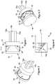
- the tool 10 comprises a body 12 defining an axis 14.
- the body 12 is of disc-like shape, and defines an end wall.
- Arrays 16 of LEDs are mounted upon the end wall of the body 12, the arrays 16 of LEDs being arranged to emit light in a direction generally parallel to the axis 14.
- the LEDs of each array 16, in this embodiment are of the type that emits ultra violet light. It will be appreciated, however, that this need not always by the case and that other types of LED may be used in some circumstances. Whilst several arrays 16, each being of generally rectangular form, are shown, it will be appreciated that the number of arrays 16 may be changed, and that the shape of the arrays 16 may differ from the form shown.
- the body 12 includes connections 12a whereby a coolant, for example in the form of water or another liquid, or in the form of a suitable gas, can be supplied to coolant passages provided in the body 12, to cool the body 12 and the LEDs mounted thereon, and whereby the warmed coolant can be conducted to a remote location.
- An electrical junction 12b is also provided whereby power and control signals can be supplied to the LEDs and associated control circuits of the arrays 16.
- the LEDs are arranged to emit light in a direction generally parallel to the axis 14, it will be appreciated that at least some of the light may be transmitted in directions angled to the axis. In practise, it is envisaged that little, if any, light will be emitted in a direction angled to the axis at an angle greater than, for example, 20 degrees.
- the expression 'generally parallel to the axis 14' should be interpreted accordingly.
- the tool 10 further comprises a reflector 18 mounted upon and carried by the body 12.
- the reflector 18 includes a reflective surface 20 at which light incident thereon emitted from the LEDs of the arrays 16 is reflected in a direction generally perpendicular to the axis 14.
- the reflected light will propagate, primarily, in a substantially radial direction angled between, for example, 70 degrees and 110 degrees relative to the axis 14.
- the reflector 18 is of generally conical form, the axis of which is aligned with the axis 14.
- the surface 20 is of substantially constant cone angle, but it could alternatively take the form of a concave parabolic or hyperbolic cone and thus be of varying cone angle. It will be appreciated that light reflected from different parts of the reflector 18 will propagate in different substantially radial directions. Where of non-constant cone angle, the reflector 18 may, in addition to serving to direct the light incident thereon in a generally radial direction, also serve to focus the reflected light. However, it will be appreciated that other forms of reflector 18 may be used without departing from the scope of the invention. By way of example, as shown, a conical reflector of constant cone angle may be used, or the reflector may be arranged to disperse rather than focus the reflected light.
- a cylindrical window or sleeve 22 is provided between the outer periphery of the reflector 18 and the outer periphery of the body 12, the window 22 protecting the reflective surface 20 of the reflector 18 and the arrays 16 of LEDs.
- the window 22 is of a material that is transparent at least to the wavelengths emitted by the LEDs.
- the window 22 may be shaped or otherwise formed in such a manner as to act as a lens, focussing the light transmitted through the window 22 onto the wall of the pipe.
- the window 22 may be provided with formations resulting in the window 22 serving as a Fresnel lens or the like.
- other lens formations may be used.
- the tool 10 may be used in the curing of resin materials applied to the inner surface of the wall of a pipe during a relining operation. After application of the resin to the wall of the pipe, the tool 10 is pushed, pulled or otherwise driven through the pipe.
- the LEDs of the arrays 16 are operated to emit ultra violet light, the light being emitted in a forward direction, generally parallel to the axis 14 of the tool 10. Operation of the LEDs is controlled via an umbilical attached at the junction 12b, and the LEDs are cooled using the coolant supplied via the connections 12a.
- the light is incident upon and reflected by the reflector 18, the reflected light propagating in a direction generally perpendicular to the axis 14, ie in a generally radial direction towards the surface of the pipe.
- the reflected light is transmitted through the window 22 interacts with the resin material in such a manner as to aid curing thereof.
- the curing tool 10 may form part of the tool used to apply the resin, if desired.
- the design of the reflector 18 and the arrangement of the arrays 16 of LEDs are conveniently such that the resin material is substantially uniformly irradiated as the tool 10 is moved along the pipe. However, depending upon the application in which the tool is to be used, it may be preferred to achieve a non-uniform pattern of irradiation.
- the tool 10 includes a single reflector 18 and associated arrays 16 of LEDs, it will be appreciated that if desired, the tool 10 may include one or more additional reflectors 18 and associated arrays of LEDs axially spaced from the reflector 18 and arrays 16.
- the tool 10 may be adapted for rotation about its axis 14.
- Figure 4 illustrates an alternative to the arrangement described hereinbefore.
- the reflector 18 serves to evenly reflect the emitted ultra violet light about the periphery of the tool 10.
- a rotatable reflector 18a is provided, a motor (not shown) being provided and arranged to drive the reflector 18a for rotation about the axis 14.
- the reflector 18a reflects the light incident thereon from the array of LEDs 16 such that the reflected light propagates in a generally radial direction, the rotation of the reflector 18 causing the reflected light to be scanned about the periphery of the tool 10 to substantially uniformly irradiate, for example, the inner surface of a wall of a pipe.
- the description hereinbefore is of a tool suitable for use in curing a material applied to the inner surface of a pipe, it will be appreciated that the tool may be used in other applications in which it is desired to irradiate a material located within an enclosed space to achieve curing thereof.
- the nature of the array of LEDs may be modified such that the light emitted therefrom is of a wavelength selected to aid curing of the particular material to be cured.
Landscapes
- Engineering & Computer Science (AREA)
- Physics & Mathematics (AREA)
- General Engineering & Computer Science (AREA)
- Health & Medical Sciences (AREA)
- Thermal Sciences (AREA)
- Oral & Maxillofacial Surgery (AREA)
- Toxicology (AREA)
- Mechanical Engineering (AREA)
- Electromagnetism (AREA)
- High Energy & Nuclear Physics (AREA)
- Heating, Cooling, Or Curing Plastics Or The Like In General (AREA)
- Combustion & Propulsion (AREA)
- Chemical & Material Sciences (AREA)
- Led Device Packages (AREA)
Applications Claiming Priority (1)
| Application Number | Priority Date | Filing Date | Title |
|---|---|---|---|
| GB1610402.8A GB2551486A (en) | 2016-06-15 | 2016-06-15 | Curing tool |
Publications (1)
| Publication Number | Publication Date |
|---|---|
| EP3257647A1 true EP3257647A1 (de) | 2017-12-20 |
Family
ID=56894806
Family Applications (1)
| Application Number | Title | Priority Date | Filing Date |
|---|---|---|---|
| EP17175766.9A Withdrawn EP3257647A1 (de) | 2016-06-15 | 2017-06-13 | Härtungswerkzeug |
Country Status (3)
| Country | Link |
|---|---|
| US (1) | US10155328B2 (de) |
| EP (1) | EP3257647A1 (de) |
| GB (1) | GB2551486A (de) |
Cited By (3)
| Publication number | Priority date | Publication date | Assignee | Title |
|---|---|---|---|---|
| WO2020011934A1 (de) * | 2018-07-13 | 2020-01-16 | I.S.T. Innovative Sewer Technologies Gmbh | Led-uv-system für die rohrsanierung |
| EP3690299A1 (de) * | 2019-02-04 | 2020-08-05 | Picote Solutions Inc. | Vorrichtung zum härten von beschichtungsmitteln |
| EP4095425A1 (de) * | 2021-05-28 | 2022-11-30 | Techra d.o.o. | Vorrichtung zum schnellen aushärten eines mit kunstharz getränkten rohrförmigen einsatzes bei der rohrleitungssanierung |
Families Citing this family (2)
| Publication number | Priority date | Publication date | Assignee | Title |
|---|---|---|---|---|
| US11674628B2 (en) | 2017-08-18 | 2023-06-13 | Moray Group, Llc | Method, apparatus and system for lining conduits |
| SE544036C2 (en) * | 2019-05-08 | 2021-11-16 | Peanta Invent Ab | Light head, with led-plate and spacer, for use in relining pipes and a light head system |
Citations (7)
| Publication number | Priority date | Publication date | Assignee | Title |
|---|---|---|---|---|
| US6102696A (en) * | 1999-04-30 | 2000-08-15 | Osterwalder; J. Martin | Apparatus for curing resin in dentistry |
| US20030170151A1 (en) * | 2002-03-08 | 2003-09-11 | Hunter Charles Eric | Biohazard treatment systems |
| DE102007038197A1 (de) * | 2007-08-14 | 2009-02-19 | Brandenburger Patentverwertung GbR (vertretungsberechtigter Gesellschafter: Wilhelm Leo Betz, 76887 Bad Bergzabern) | Verfahren und Vorrichtung zum Sanieren von Rohrleitungen |
| US20090175977A1 (en) * | 2008-01-09 | 2009-07-09 | Sony Corporation | Optical molding apparatus, optical molding method, and optically molded product |
| EP2129956A1 (de) * | 2007-02-19 | 2009-12-09 | Per Aarsleff A/S | Vorrichtung und verfahren zum aushärten einer auskleidung einer rohrleitung |
| US20100308510A1 (en) * | 2007-11-04 | 2010-12-09 | Thomas Reutemann | Device for curing plastic liners used for rehabilitating ducts |
| US20150273761A1 (en) * | 2011-08-11 | 2015-10-01 | The Boeing Company | Heating system for composite rework of aircraft |
Family Cites Families (8)
| Publication number | Priority date | Publication date | Assignee | Title |
|---|---|---|---|---|
| US5616141A (en) * | 1993-04-09 | 1997-04-01 | Ion Laser Technology | Laser system for use in dental procedures |
| US6910886B2 (en) * | 1999-09-24 | 2005-06-28 | Cao Group, Inc. | Curing light |
| US6719559B2 (en) * | 1999-09-24 | 2004-04-13 | Densen Cao | Curing light |
| US6929472B2 (en) * | 1999-09-24 | 2005-08-16 | Cao Group, Inc. | Curing light |
| US7857619B2 (en) * | 2005-02-26 | 2010-12-28 | Yongqian Liu | LED curing light having fresnel lenses |
| JP5025404B2 (ja) * | 2007-09-28 | 2012-09-12 | 吉佳エンジニアリング株式会社 | 管路補修ライニング材用の光照射装置、光照射システム及びこれら装置又はシステムを用いた光硬化方法 |
| US20090208894A1 (en) * | 2008-02-18 | 2009-08-20 | Discus Dental, Llc | Curing Light |
| DE102011109386B3 (de) * | 2011-08-04 | 2013-01-17 | Heraeus Noblelight Gmbh | Vorrichtung zum Aushärten von Beschichtungen oder Kunststofflinern auf der Innenwandung langgestreckter Hohlräume |
-
2016
- 2016-06-15 GB GB1610402.8A patent/GB2551486A/en not_active Withdrawn
-
2017
- 2017-06-13 EP EP17175766.9A patent/EP3257647A1/de not_active Withdrawn
- 2017-06-14 US US15/622,224 patent/US10155328B2/en not_active Expired - Fee Related
Patent Citations (7)
| Publication number | Priority date | Publication date | Assignee | Title |
|---|---|---|---|---|
| US6102696A (en) * | 1999-04-30 | 2000-08-15 | Osterwalder; J. Martin | Apparatus for curing resin in dentistry |
| US20030170151A1 (en) * | 2002-03-08 | 2003-09-11 | Hunter Charles Eric | Biohazard treatment systems |
| EP2129956A1 (de) * | 2007-02-19 | 2009-12-09 | Per Aarsleff A/S | Vorrichtung und verfahren zum aushärten einer auskleidung einer rohrleitung |
| DE102007038197A1 (de) * | 2007-08-14 | 2009-02-19 | Brandenburger Patentverwertung GbR (vertretungsberechtigter Gesellschafter: Wilhelm Leo Betz, 76887 Bad Bergzabern) | Verfahren und Vorrichtung zum Sanieren von Rohrleitungen |
| US20100308510A1 (en) * | 2007-11-04 | 2010-12-09 | Thomas Reutemann | Device for curing plastic liners used for rehabilitating ducts |
| US20090175977A1 (en) * | 2008-01-09 | 2009-07-09 | Sony Corporation | Optical molding apparatus, optical molding method, and optically molded product |
| US20150273761A1 (en) * | 2011-08-11 | 2015-10-01 | The Boeing Company | Heating system for composite rework of aircraft |
Cited By (6)
| Publication number | Priority date | Publication date | Assignee | Title |
|---|---|---|---|---|
| WO2020011934A1 (de) * | 2018-07-13 | 2020-01-16 | I.S.T. Innovative Sewer Technologies Gmbh | Led-uv-system für die rohrsanierung |
| US20210293367A1 (en) * | 2018-07-13 | 2021-09-23 | I.S.T. Innovative Sewer Technologies Gmbh | LED UV System for Pipe Rehabilitation |
| US12338936B2 (en) * | 2018-07-13 | 2025-06-24 | Trelleborg Sealing Profiles Germany Gmbh | LED UV system for pipe rehabilitation |
| EP3690299A1 (de) * | 2019-02-04 | 2020-08-05 | Picote Solutions Inc. | Vorrichtung zum härten von beschichtungsmitteln |
| WO2020161054A1 (en) * | 2019-02-04 | 2020-08-13 | Picote Solutions Inc. | Device for curing coating substance |
| EP4095425A1 (de) * | 2021-05-28 | 2022-11-30 | Techra d.o.o. | Vorrichtung zum schnellen aushärten eines mit kunstharz getränkten rohrförmigen einsatzes bei der rohrleitungssanierung |
Also Published As
| Publication number | Publication date |
|---|---|
| GB201610402D0 (en) | 2016-07-27 |
| US10155328B2 (en) | 2018-12-18 |
| GB2551486A (en) | 2017-12-27 |
| US20170361506A1 (en) | 2017-12-21 |
Similar Documents
| Publication | Publication Date | Title |
|---|---|---|
| US10155328B2 (en) | Curing tool | |
| JP6017573B2 (ja) | 光ファイバーを硬化するための共同設置焦点を有する多重光収集とレンズの組合せ | |
| CN102408198B (zh) | 用于提供提高的uvled强度的方法和设备 | |
| KR102078651B1 (ko) | 과도 집속 방지 기능을 갖는 초점 가변형 hifu 어셈블리 | |
| JP6605464B2 (ja) | 硬化装置、光反応システム、及び、方法 | |
| US20170050166A1 (en) | Irradiation systems using curved surfaces | |
| US5247178A (en) | Method and apparatus for treating fluids by focusing reflected light on a thin fluid layer | |
| JP6689027B2 (ja) | 高輝度光源用の変換器ユニットの冷却 | |
| JP6705016B2 (ja) | 構成層のキャリア対象への接着性を向上させるための装置及び方法 | |
| EP2388239A1 (de) | Härtungsvorrichtung mit in einem Winkel gerichteter UV-LEDs | |
| JP2013500815A5 (de) | ||
| US11267168B2 (en) | Structure forming apparatus, structure manufacturing method, and structure | |
| JP2002260595A5 (de) | ||
| CN108883498B (zh) | 用于激光透射焊接环形焊缝的装置 | |
| CA2473042A1 (en) | Solar energy control | |
| US12338936B2 (en) | LED UV system for pipe rehabilitation | |
| US9287078B2 (en) | Display sealing apparatus and method of manufacturing display apparatus by using the same | |
| WO2016011093A1 (en) | Solar rejection system with movable sunshade | |
| JP2020006329A (ja) | 紫外線照射装置 | |
| ES2990073T3 (es) | Sistema para curar y/o inspeccionar un revestimiento de tubería y método para curar y/o inspeccionar un revestimiento de tubería | |
| JPH02290914A (ja) | 金属工作物の表面を熱的に硬化する方法並びにこの方法を実施するための装置 | |
| KR970000774B1 (ko) | 회전식 스크린 인쇄 스텐슬에 엔드 링을 고정시키기 위한 장치 | |
| CN216497089U (zh) | 驱动机构、以及包括该驱动机构的超声治疗仪的手具 | |
| JP2007333869A (ja) | 紫外線照射装置 | |
| EP4095425A1 (de) | Vorrichtung zum schnellen aushärten eines mit kunstharz getränkten rohrförmigen einsatzes bei der rohrleitungssanierung |
Legal Events
| Date | Code | Title | Description |
|---|---|---|---|
| PUAI | Public reference made under article 153(3) epc to a published international application that has entered the european phase |
Free format text: ORIGINAL CODE: 0009012 |
|
| AK | Designated contracting states |
Kind code of ref document: A1 Designated state(s): AL AT BE BG CH CY CZ DE DK EE ES FI FR GB GR HR HU IE IS IT LI LT LU LV MC MK MT NL NO PL PT RO RS SE SI SK SM TR |
|
| AX | Request for extension of the european patent |
Extension state: BA ME |
|
| 17P | Request for examination filed |
Effective date: 20180221 |
|
| RBV | Designated contracting states (corrected) |
Designated state(s): AL AT BE BG CH CY CZ DE DK EE ES FI FR GB GR HR HU IE IS IT LI LT LU LV MC MK MT NL NO PL PT RO RS SE SI SK SM TR |
|
| 17Q | First examination report despatched |
Effective date: 20190805 |
|
| GRAP | Despatch of communication of intention to grant a patent |
Free format text: ORIGINAL CODE: EPIDOSNIGR1 |
|
| INTG | Intention to grant announced |
Effective date: 20200114 |
|
| RIN1 | Information on inventor provided before grant (corrected) |
Inventor name: LOCKWOOD, ADRIAN Inventor name: SMITH, JASON |
|
| STAA | Information on the status of an ep patent application or granted ep patent |
Free format text: STATUS: THE APPLICATION IS DEEMED TO BE WITHDRAWN |
|
| 18D | Application deemed to be withdrawn |
Effective date: 20200603 |