EP3257663A1 - Procédé de fabrication de semi-produits pour éléments structuraux composites fibres/plastique - Google Patents
Procédé de fabrication de semi-produits pour éléments structuraux composites fibres/plastique Download PDFInfo
- Publication number
- EP3257663A1 EP3257663A1 EP17175903.8A EP17175903A EP3257663A1 EP 3257663 A1 EP3257663 A1 EP 3257663A1 EP 17175903 A EP17175903 A EP 17175903A EP 3257663 A1 EP3257663 A1 EP 3257663A1
- Authority
- EP
- European Patent Office
- Prior art keywords
- layers
- fiber
- layer
- fibers
- continuous
- Prior art date
- Legal status (The legal status is an assumption and is not a legal conclusion. Google has not performed a legal analysis and makes no representation as to the accuracy of the status listed.)
- Granted
Links
Images

Classifications
-
- B—PERFORMING OPERATIONS; TRANSPORTING
- B29—WORKING OF PLASTICS; WORKING OF SUBSTANCES IN A PLASTIC STATE IN GENERAL
- B29C—SHAPING OR JOINING OF PLASTICS; SHAPING OF MATERIAL IN A PLASTIC STATE, NOT OTHERWISE PROVIDED FOR; AFTER-TREATMENT OF THE SHAPED PRODUCTS, e.g. REPAIRING
- B29C70/00—Shaping composites, i.e. plastics material comprising reinforcements, fillers or preformed parts, e.g. inserts
- B29C70/04—Shaping composites, i.e. plastics material comprising reinforcements, fillers or preformed parts, e.g. inserts comprising reinforcements only, e.g. self-reinforcing plastics
- B29C70/28—Shaping operations therefor
- B29C70/30—Shaping by lay-up, i.e. applying fibres, tape or broadsheet on a mould, former or core; Shaping by spray-up, i.e. spraying of fibres on a mould, former or core
- B29C70/38—Automated lay-up, e.g. using robots, laying filaments according to predetermined patterns
- B29C70/382—Automated fiber placement [AFP]
-
- B—PERFORMING OPERATIONS; TRANSPORTING
- B29—WORKING OF PLASTICS; WORKING OF SUBSTANCES IN A PLASTIC STATE IN GENERAL
- B29B—PREPARATION OR PRETREATMENT OF THE MATERIAL TO BE SHAPED; MAKING GRANULES OR PREFORMS; RECOVERY OF PLASTICS OR OTHER CONSTITUENTS OF WASTE MATERIAL CONTAINING PLASTICS
- B29B11/00—Making preforms
- B29B11/14—Making preforms characterised by structure or composition
- B29B11/16—Making preforms characterised by structure or composition comprising fillers or reinforcement
Definitions
- the present invention relates to a method for producing sheet-like, fiber-reinforced semi-finished products for fiber-plastic composite components, in which continuous fibers are deposited in at least two layers one above the other during a continuous transport of these layers carried out by means of a layer transport mechanism, wherein the fiber orientation in a first layer of at least two layers differs from the fiber orientation in at least one other layer of the at least two layers during the transport of the at least two layers.
- Fiber-reinforced plastics consist of reinforcing fibers and a plastic matrix surrounding the fibers, with the mechanical and thermal properties of fiber reinforced plastics being adjustable over a variety of parameters.
- the properties of fiber-reinforced plastics can be influenced by varying the fiber orientation, the fiber volume fraction, the layer order and formation, the fiber length, the properties of the fibers and / or the matrix material.
- Fiber-reinforced plastics can be produced for example by means of injection molding, extrusion or as a sheet molding compound. Frequently, however, fiber-reinforced plastics are formed as laminates, since in this case the advantages of an individual fiber alignment can be exploited.
- the laminates used for this purpose generally consist of fiber layers arranged one above the other, the fibers of which are arranged in different directions of fibers.
- a method for producing a fiber-reinforced plastic component in which a preform is preferably made of at least three stacked, solidified under pressure and heat and optionally formed three-dimensionally deformed semi-finished fiber blanks.
- the semifinished fiber blanks are produced by parallel laying and fixing of endless reinforcing threads in final contour on a continuously conveyed in a conveying direction endless carrier web and subsequent cutting of the endless carrier web according to a semi-final contour.
- the endless reinforcing threads of the individual semifinished fiber blanks have different reinforcing thread orientations. This is realized in that for the formation of the semifinished fiber blanks surface and contour same, but rotated at an angle to the conveying direction of the endless carrier sheet fabric cut out of the deposited fabric and then placed one above the other.
- a disadvantage of this type of production of preforms for fiber-reinforced plastic components is that for each of the layers of the preform each serving as a support material lower or intermediate layer is required, which worsen the characteristics of the component to be formed from the preform.
- the object is achieved by a method of the above type, wherein the continuous fibers of the at least two layers without lateral support of the continuous fibers in one of the width of a used conveyor belt and / or the width of the layer transport mechanism independent, but not across the width of the conveyor belt and / or the width of the layer transport mechanism extending Halbzeugendkonturform straight stored and cut according to the respective width of the Halbzeugendkonturform after depositing and at least one region of the Halbzeugendkonturform on the layers at least one gain-forming continuous reinforcing fiber is laid.
- continuous fibers in a semifinished contour shape are deposited on a carrier material or a conveyor belt and cut to length according to the respective width of the semifinished final contour.
- the continuous fibers of the first layer are just laid and have a first fiber orientation.
- the continuous fibers are first cut to length, such as cut off, for example, when the respective endless fiber has been at least partly deposited on the carrier material or the conveyor belt.
- the continuous fiber is already cut to length, even if it already, but not yet completely on the substrate or the conveyor belt rests.
- the end of the cut-to-length endless fiber, which has not yet been resting on the carrier material or the conveyor belt then falls onto the carrier material or the conveyor belt.
- the cutting is thus carried out according to the invention when laying the continuous fibers on the substrate or the conveyor belt.
- the depositing and cutting takes place during the preferably continuous transport or further transport of the already deposited endless fibers.
- the semifinished contour shape is formed by a plurality of individual rovings obtained from the continuous fibers by cutting to length, wherein the individual rovings are cut to near net shape when deposited on the carrier material or the conveyor belt.
- the individual endless fibers are laid uniformly distributed over the complete semifinished final contour shape, all endless fibers of this layer each having the same fiber orientation.
- the at least one layer transporting conveyor belt is further moved and / or the sheet transport mechanism continuously operated, whereby the manufacturing time for the production of the fiber-reinforced semifinished product can be kept as low as possible.
- first laying device in the conveying direction of the first layer second laying means are applied directly to the first layer at least one further layer forming continuous fibers, whereby also here the conveyor belt or the layer transport mechanism is continuously operated.
- the continuous fibers forming the at least one further layer are also laid in the final contour shape of the semifinished product, wherein the continuous fibers of the further layer have a fiber orientation which differs from the fiber orientation of the endless fibers of the first layer. Due to the different fiber orientations of the layers deposited on one another, in particular the strength and stability of the semifinished product produced can be increased.
- the continuous fibers forming the further layer are preferably laid evenly distributed over the semi-final contour shape with the same fiber orientation.
- the continuous fibers of the individual layers are each laid in a straight line, since this allows the inventive method can be realized with high efficiency.
- the number of layers arranged one above the other can vary. Insofar as more than two layers are stored, additional laying devices for depositing further layers adjoin the first two laying devices in the layer transport direction.
- the number of layers of the semifinished product should be selected specific to the application.
- the fiber orientation directions of the continuous fibers of the first to nth layers are different from each other.
- at least one of the layers three to n may also have one of the endless reinforcing fiber orientation direction of the first or second layer and / or one of the layers deposited thereon corresponding fiber orientation direction.
- the method according to the invention works semi-generically in contour, continuously, is suitable for mass production and is highly productive.
- At least one additional, stabilizing and / or functional filling intermediate layer can additionally be introduced between the individual layers of continuous fibers.
- the continuous fibers of the individual layers are laid down in semifinished contour shape, regardless of the width of the conveyor belt used and / or layer transport mechanism, but not beyond the width of the conveyor belt and / or layer transport mechanism, whereby a cost-effective fiber-reinforced Semi-finished can be produced without or with a very small proportion of waste material.
- the continuous fibers in Halbzeugendkonturform can be dispensed with, especially when no additional carrier material is used to form the semi-finished to cut the formed by the deposition of continuous filaments layers, whereby the machining process can be shortened and the manufacturing and material costs can be reduced.
- the deposited layers can also be additionally cut and / or punched. In this case, either the complete semi-finished contour shape or only part of the semi-final contour shape can be cut and / or punched out.
- the continuous fibers are cut to length after depositing to one of the layers during the transport of the respective layer.
- the production time for the production of the fiber-reinforced semifinished product is substantially shortened.
- the control effort of the semi-finished production plant used is reduced by the thus continuously enabled layer transport.
- the cutting to length of the continuous fibers can take place, for example, by means of laser, ultrasound, water jet or mechanical cutting.
- the at least one continuous reinforcing fiber or fiber can also be torn or cut in some other form, such as torn off.
- At least one reinforcing fiber forming a reinforcement is laid on the layers in at least one region of the semi-final contour shape.
- the semifinished product By depositing the at least one continuous reinforcing fiber on the previously formed at least two layers of the semifinished product, the semifinished product can be reinforced in a load-specific manner and thus withstand higher loads.
- the shape and dimension of the reinforcement formed from the at least one endless reinforcing fiber and their arrangement on the semifinished final contour shape are to be selected specific to the application. Furthermore, the number of reinforcements applied to the semi-final contour shape can also vary in an application-specific manner.
- the reinforcement made of endless reinforcing fibers does not necessarily have to be applied to the deposited layers, but can also be introduced between two layers of the semi-finished product.
- At least one continuous reinforcement fiber of the reinforcement of a given reinforcement contour can be laid, for example meander-shaped and / or undulating and / or zigzag-shaped and / or randomly in accordance with a predetermined reinforcement contour.
- the distance between adjacent sections of continuous reinforcing fibers of the reinforcement may vary over the length of the adjacent sections. Thus, it is possible, for example, to pass the endless reinforcing fibers around certain force introduction points of the later component.
- the at least one endless reinforcing fiber forming the reinforcement is laid in a predetermined contour.
- the endless reinforcing fiber (s), as already mentioned above, be laid with varying distance from each other, which can be particularly well formed in the semifinished product, for example by deformation generated kinks, constrictions or the like.
- the distance between the reinforcing reinforcing fiber (s) forming the reinforcement can be reduced relative to one another and a comparatively large distance can be selected in regions of lesser stress, so that a tapering point is formed in the reinforcement.
- the use of continuous reinforcing fibers can be reduced and thus the cost and weight of the semifinished product to be produced can be minimized.
- the at least one endless reinforcing fiber of the reinforcement is laid on the load path.
- the at least one endless reinforcing fiber of the reinforcement is laid on the load path.
- the at least two layers are deposited directly on a surface of the conveyor belt, without use of a carrier material under or between these layers.
- the material and manufacturing costs can be kept low because, for example, the cost of the carrier material and the cost of handling this account.
- the production process itself is simplified, since among other things, the supply of the carrier material and the bonding of the carrier material with the continuous fibers are eliminated.
- only semifinished products produced from continuous fibers without additional carrier material also have a lower weight, which can be used advantageously in particular for lightweight construction applications.
- an additional carrier material below and / or between and / or over the at least two layers can also be used to produce the semifinished product.
- this carrier material can thus be supplied as a base and / or intermediate and / or top layer to the layers formed from the continuous fibers.
- the carrier material can either be supplied to the production process as a material web and be cut to a later date or already supplied tailored to the manufacturing process.
- the carrier material preferably has the Halbzeugendkonturform, but may also have any other shape and thus cover the formed from the at least two layers with the reinforcement Halbzeugendkonturform completely or only partially.
- the continuous fibers of at least one of the at least two layers are laid at a distance from each other in the respective layer, which is from 6 mm to 100 mm.
- the distance between the continuous fibers within the respective layer is preferably the same size.
- the arrangements of the continuous fibers with uniform spacing from one another can produce semifinished products with constant load resistance over the entire semifinished product surface.
- the distance between the continuous fibers or parts of continuous fibers should be selected as a function of the component geometry.
- the continuous fibers can also be laid at a distance of less than 6 mm or greater than 100 mm from each other.
- the continuous fibers within a layer in alternative embodiments of the present invention can also be laid with different sized, the partial load of the semi-finished adjusted to each other.
- dry filaments or fiber composites, hybrid fibers formed from reinforcing and matrix fibers, binded filaments or fiber composites are used during the semifinished production process used filaments or fiber composites to be bindered and / or thermoplastic unidirectional tapes as continuous fibers and / or continuous reinforcing fiber.
- individual filaments, fibers and / or fiber composites can be joined or secured against slipping.
- bind for example, thermoplastic polymers are used, which are sprayed flat on the filaments, fibers and / or fiber bundles, scattered or applied surface. By heating, the binders become sticky, whereby a fixation is achieved.
- filaments and / or fibers of carbon, boron, glass, ceramic, basalt and / or aramid can be used for the formation of the continuous fibers and / or continuous reinforcement fiber (n), which binds dry, as hybrid fibers formed from reinforcing and matrix fibers or used during the manufacturing process to be soothing.
- fibers, fiber bundles or filaments for forming the continuous fibers and / or continuous reinforcement fibers, which need not necessarily be bridged.
- Such fibers, filaments or fiber bundles can also be coated by means of another coating method, for example.
- unidirectional tapes may also be used in the production of a fiber-reinforced semi-finished product.
- Unidirectional tapes are to be understood in particular as densely packed strands, for example held in position by a resin.
- the individual juxtaposed strands can also be held together by weft threads which are injected transversely into the juxtaposed strands.
- fibers, fiber bundles, filaments and / or unidirectional tapes having the same or different properties can be used within one layer.
- the fibers, Fiber bundles, filaments and / or unidirectional bands of the individual layers differ from each other or be the same.
- the continuous fibers of each of the at least two layers are thus each aligned unidirectionally in the method according to the invention.
- the continuous fiber reinforcing fibers of the reinforcement are designed for load paths, so they can be laid, for example, wave-shaped, zigzag-shaped or in another, expedient embodiment.
- the method according to the invention therefore combines the semiproductive contour-corresponding depositing of the continuous fibers in the at least two layers with the load path-compatible support of the at least one endless reinforcement fiber of the reinforcement.
- the layer transport for depositing and / or cutting the continuous fibers and / or the at least one endless reinforcement fiber can also be performed in a clocked manner.
- the continuous fibers lying next to each other in the at least two layers are preferably formed from spread individual rovings and have a basis weight in the respective layer in a range from 50 to 300 g / m 2 . Different basis weights are possible in the different layers of the semi-finished product.
- the respective surface weight of the layer is determined by the continuous fiber prefor product used, that is to say by the continuous fiber bobbin used in each case.
- a 50K roving ie a fiber strand consisting of 50,000 individual filaments, having a width of about 14 to 15 mm and a basis weight of about 300 g / m 2 are used, which is spread by a method according to the invention upstream spreading process in Einzelrovings, for example, have a basis weight of 150 g / m 2 and are then used as continuous fibers to form the at least two layers.
- other rovings such as 24K roving, can be used.
- the layers deposited in the semi-final contour shape can be thermally, mechanically and / or chemically solidified and thus fixed in their shape.
- the thermal, mechanical and / or chemical solidification takes place then, when all the layers are stored.
- intermediate consolidation of individual layer arrangements may also take place.
- the solidification and / or fixation of the layers can not take place only at the end of the layer deposition process, but can also be carried out, for example, after depositing each individual layer of the semifinished product, every second, every nth or after a varying, irregular number of deposited layers become.
- a solidification and / or fixation of the layers can be done for example by pressure and / or temperature in the form of infrared radiation, ultrasound, hot air, laser treatment or the like.
- the chemical, thermal and / or mechanical solidification and / or fixation of at least one of the layers can according to the invention localized, for example, be made only on the side edges of the semi-final contour, punctiform or over the entire surface of the Halbzeugendkonturform.
- the at least two layers of the semifinished product produced by the method according to the invention preferably have a symmetrical arrangement of the endless fibers used, that is to say a mirror symmetry of the layers in the thickness direction of a layer stack formed from the at least two layers.
- this can also be realized by first forming a layer stack which is asymmetrical in its layers, on the back side of which the same layer stack is mirror-symmetrically formed on the reverse side of the first process run of the method according to the invention in a second process run of the method according to the invention Layer stack is applied. This results in a semi-finished product and later a component that can be produced therefrom with an isotropic force absorption.
- a semi-finished product which is mirror-symmetrical with respect to its force absorption can also be formed by forming a first reinforcement from at least one continuous reinforcing fiber on the at least two layers in a first process run and in a second process run on the back side of the layer stack formed from the at least two layers a second, mirror-symmetrical to the first gain formed reinforcement of at least an endless reinforcing fiber is formed.
- the load path on the front and back of the semifinished product forms a mirror image.
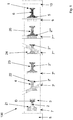
- FIG. 1 schematically shows a possible embodiment of a system 100, on which a variant of the method according to the invention is executable, in a plan view.
- a plurality of parallel endless fibers 2 are deposited directly on a conveyor belt 3 in a final contour shape of a semifinished product 1 to be produced in a first laying device 7.
- the filaments 2 deposited by the first laying unit 7 form a first layer 21 of the semifinished product 1 to be produced.
- the continuous fibers 2 of the first layer 21 are aligned in the transport direction of the layers 21, 22, 23, 24, 25 and have a constant distance D from each other.
- the continuous fibers 2 of the first layer 21 may also have a different fiber orientation than the one shown and / or a distance other than the one shown.
- the continuous fibers 2 can be laid at least partially overlapping.
- the endless fibers 2 forming the first layer 21 are cut to length.
- the cutting to length of the continuous fibers 2 can preferably be effected by means of a lengthening device which is coupled or can be coupled to the laying unit 7, wherein the cutting can be effected, for example, by means of laser, water jet, ultrasound or mechanically.
- the first layer 21 deposited in the first laying unit 7 is conveyed by means of the continuously driven conveyor belt 3 to a second laying unit 7 'following in the direction of transport, in which directly on the first layer 21 a second layer 22 consisting of continuous fibers 2' is deposited.
- the second layer 22 is also deposited in the semi-final contour shape to be produced.
- the conveyor belt 3 is driven continuously in this embodiment by a drive mechanism 8, but can also be operated cyclically in alternative embodiments.
- the second layer 22 forming continuous fibers 2 'to the continuous fibers 2 of the first layer 21 different fiber orientation.
- the endless fibers 2 'of the second layer are arranged inclined by about 100 ° to the filaments 2 of the first layer 21, but can be aligned in alternative embodiments at a different angle to the filaments 2 of the first layer 21.
- continuous fibers 2 of the first layer 21, and the continuous fibers 2 'of the second layer 22 are preferably rectilinear, parallel, with a defined distance D to each other laid, but can also be laid as the continuous fibers 2 of the first layer 21 in a different manner.
- the continuous fibers 2 "of the third layer 23 have a fiber orientation different from the endless fibers 2, 2 'of the first two layers 21, 22, but can also be combined with one of the endless fibers 2, 2' of the first or second layer 21, 22 corresponding fiber orientation are stored.
- the layers 21, 22, 23 are conveyed to a fourth laying device 7" ', where a fourth layer 24 of continuous fibers 2' "onto the first three layers 21, 22, 23
- the continuous fibers 2 '"of the fourth layer 24 advantageously have a fiber orientation which differs from the fiber orientation of the endless fibers 2, 2', 2" of the first three layers 21, 22, 23, but can also be combined with one of the alternative embodiments first, second and / or third layer 21, 22, 23 corresponding fiber orientation are laid.
- the continuously moving conveyor belt 3 conveys the first four layers 21, 22, 23, 24 to a fifth installation device 7 "", where a fifth layer 25 in semi-final contour shape is applied to the previously deposited four layers 21, 22, 23, 24.
- the fifth layer 25 forming endless fibers 2 "" have in the in FIG. 1 embodiment shown, the same orientation and the same distance as the continuous fibers 2 of the first layer 21, however, can also be stored in a further embodiment variants with a different orientation and / or arrangement on the fourth layer 24.
- the semi-finished product is formed from fewer or more than five layers 21, 22, 23, 24, 25 and / or a different orientation and arrangement of the continuous fibers 2, 2 ', 2 " , 2 "', 2""of the individual layers 21, 22, 23, 24, 25 is selected.
- the endless fibers 2, 2 ', 2 ", 2"', 2 “” are merely deposited on the conveyor belt 3, without being lodged in a holder provided on or in the vicinity of the conveyor belt 3, clamped, wrapped around it or in a similar manner Way to be attached to this.
- This has the advantage that any Endkonturform, completely independent of the width of the conveyor belt 3 can be set and at the same time the production time of the semi-finished product to be produced, as a time-consuming and difficult to betechnikstelligendes looping, pinching or inserting the continuous fibers 2 in one or a holder can be avoided.
- the layers 21, 22, 23, 24, 25 as in FIG. 1 are transported to a solidification fiber laying device 9, in which at least one continuous strengthening fiber 5 forming a reinforcement 6 is deposited on the layers 21, 22, 23, 24, 25.
- the reinforcement 6 serves in particular to increase the stability of the semifinished product 1 to be produced in areas with particularly high loads.
- the reinforcement 6 is formed from at least one continuous reinforcement fiber 5 laid in a predetermined contour.
- the reinforcement 6 is applied only in a certain area of the semifinished product 1, but can also be provided over the complete semi-final contour shape.
- the layers 21, 22, 23, 24, 25 with the applied reinforcement 6 are thermally, chemically and / or mechanically solidified and / or fixed in a solidification device 10.
- the solidification and / or fixation of the layers 21, 22, 23, 24, 25, however, also take place at another point of the method.
- solidification and / or fixation can also be provided at several points of the method.
- the first layer 21 of continuous fibers 2 can in this case be connected to the carrier material by sewing, gluing, fusing or the like, or else merely processed further on the carrier material.
- the carrier material used can be supplied to the process as a carrier web and cut in a subsequent process step or else already having the semi-final contour shape or another arbitrary shape possessing the process.
- the carrier material is provided covering at least two layers 21, 22, 23, 24, 25 and / or covering layers 21, 22, 23, 24, 25.
- the use of an additional carrier material offers in particular the advantages that the handling and the stability of the semifinished product can be improved.
- FIG. 2 schematically shows a producible with first steps of the method according to the invention, for example, from two superimposed layers 21, 22 of continuous fibers 2, 2 'formed semi-finished product precursor 1a in a plan view
- FIG. 3 schematically a possible embodiment of an on the basis of the semi-precursor from FIG. 2 shows with further steps of the method according to the invention producible semifinished product 1 in a plan view
- the semifinished product 1 has two layers 21, 22 with a reinforcement 6 made of endless reinforcing fibers 5.
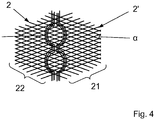
- FIG. 4 is another, with the aid of the method according to the invention producible semifinished product 1 ', are performed in the continuous reinforcing fibers 5 to force application points 11 of a component to be produced.
- FIGS. 2 to 4 denote the same reference numerals as in FIG FIG. 1 same components, which is why reference is made to the preceding description of these components.
- the superimposed layers 21, 22 are formed from individual continuous fibers 2, 2 ', wherein the continuous fibers 2' of the second layer 22 are arranged at an angle ⁇ to the continuous fibers 2 of the first layer 21.
- the size of the angle ⁇ is to be selected specific to the application.
- shape of the superimposed layers 21, 22 is selected only by way of example and may, depending on the embodiment of the semifinished product 1 to be produced have any other shape.
- FIG. 3 1 schematically shows a semi-finished product 1 which can be produced by the method according to the invention and which has a reinforcement 6 deposited on the layers 21, 22 of individual endless fibers 5.
- the endless reinforcing fibers 5 are laid to match the reinforcement 6 of a predetermined contour, wherein a distance D, D 'varying over the length of the endless reinforcing fibers 5 is provided between the individual endless reinforcing fibers 5 of the reinforcement 6.
- the individual continuous reinforcing fibers 5 of the reinforcement 6 can also be laid at a constant distance from one another.
- the reinforcement 6 is applied only locally limited to the semi-final contour forming layers 21, 22, but may also be provided over the entire Halbmaschineendkonturform. Furthermore, a plurality of partially provided reinforcements 6 can be applied to the at least two layers 21, 22, 23, 24, 25.
- FIG. 4 is schematically and again an example based on the semi-finished product precursor 1a FIG. 2 formed with the inventive method semifinished product 1 ', shown in a plan view, in which case the endless reinforcing fibers 5 are guided around later force introduction points 11 of the semifinished product 1' to be produced component.
- the endless reinforcing fibers 5 guided around the force introduction points 11 effecting a suitable stabilization of the geometry even when the force is introduced into the force introduction points 11.
- the endless reinforcing fibers 5 or the continuous fibers 2, 2', 2 ", 2" ', 2 "" can also be laid in a different form than shown in the figures.
- the semifinished product 1 to be produced may also have a different final contour shape and / or be formed from a different number of layers 21, 22, 23, 24, 25.
Landscapes
- Engineering & Computer Science (AREA)
- Mechanical Engineering (AREA)
- Robotics (AREA)
- Chemical & Material Sciences (AREA)
- Composite Materials (AREA)
- Reinforced Plastic Materials (AREA)
- Moulding By Coating Moulds (AREA)
Applications Claiming Priority (1)
| Application Number | Priority Date | Filing Date | Title |
|---|---|---|---|
| DE102016111080.9A DE102016111080B4 (de) | 2016-06-17 | 2016-06-17 | Verfahren zum Herstellen von Halbzeugen für Faser-Kunststoff-Verbundbauteile |
Publications (2)
| Publication Number | Publication Date |
|---|---|
| EP3257663A1 true EP3257663A1 (fr) | 2017-12-20 |
| EP3257663B1 EP3257663B1 (fr) | 2020-09-30 |
Family
ID=59061876
Family Applications (1)
| Application Number | Title | Priority Date | Filing Date |
|---|---|---|---|
| EP17175903.8A Active EP3257663B1 (fr) | 2016-06-17 | 2017-06-14 | Procédé de fabrication de semi-produits pour éléments structuraux composites fibres/plastique |
Country Status (2)
| Country | Link |
|---|---|
| EP (1) | EP3257663B1 (fr) |
| DE (1) | DE102016111080B4 (fr) |
Cited By (1)
| Publication number | Priority date | Publication date | Assignee | Title |
|---|---|---|---|---|
| CN110065242A (zh) * | 2018-01-23 | 2019-07-30 | 波音公司 | 具有连续和短切纤维组分二者的复合材料部件的制造 |
Citations (2)
| Publication number | Priority date | Publication date | Assignee | Title |
|---|---|---|---|---|
| DE102004060674A1 (de) * | 2004-12-15 | 2006-07-06 | Eurocopter Deutschland Gmbh | Verfahren und eine Vorrichtung zur Herstellung eines flächigen Faser-Vorformlings |
| JP2014189908A (ja) * | 2013-03-26 | 2014-10-06 | Toray Ind Inc | プリフォームの製造方法および製造装置 |
Family Cites Families (5)
| Publication number | Priority date | Publication date | Assignee | Title |
|---|---|---|---|---|
| FR2761380B1 (fr) * | 1997-03-28 | 1999-07-02 | Europ Propulsion | Procede et machine pour la realisation de nappes fibreuses multiaxiales |
| DE10005202B4 (de) | 2000-02-03 | 2007-03-01 | Institut Für Verbundwerkstoffe Gmbh | Verfahren und Vorrichtung zur kontinuierlichen bauteil- und prozessorientierten Herstellung von Verstärkungsstruktur-Halbzeugen für Faser-Kunststoff-Verbundwerkstoffe |
| DE10060379B4 (de) | 2000-12-05 | 2004-10-28 | Fraunhofer-Gesellschaft zur Förderung der angewandten Forschung e.V. | Verfahren zur Herstellung von multidirektionalen Faden- oder Fasergelegen |
| AT511349B1 (de) * | 2011-09-21 | 2012-11-15 | Kapsch Group Beteiligungs Gmbh | Faserhalbzeug, faser-verbundwerkstoff und verfahren zu deren herstellung |
| DE102013216835B4 (de) | 2013-08-23 | 2017-01-05 | Volkswagen Aktiengesellschaft | Verfahren zur Herstellung eines faserverstärkten Kunststoffbauteils |
-
2016
- 2016-06-17 DE DE102016111080.9A patent/DE102016111080B4/de not_active Expired - Fee Related
-
2017
- 2017-06-14 EP EP17175903.8A patent/EP3257663B1/fr active Active
Patent Citations (2)
| Publication number | Priority date | Publication date | Assignee | Title |
|---|---|---|---|---|
| DE102004060674A1 (de) * | 2004-12-15 | 2006-07-06 | Eurocopter Deutschland Gmbh | Verfahren und eine Vorrichtung zur Herstellung eines flächigen Faser-Vorformlings |
| JP2014189908A (ja) * | 2013-03-26 | 2014-10-06 | Toray Ind Inc | プリフォームの製造方法および製造装置 |
Cited By (2)
| Publication number | Priority date | Publication date | Assignee | Title |
|---|---|---|---|---|
| CN110065242A (zh) * | 2018-01-23 | 2019-07-30 | 波音公司 | 具有连续和短切纤维组分二者的复合材料部件的制造 |
| CN110065242B (zh) * | 2018-01-23 | 2022-11-29 | 波音公司 | 具有连续和短切纤维组分二者的复合材料部件的制造 |
Also Published As
| Publication number | Publication date |
|---|---|
| EP3257663B1 (fr) | 2020-09-30 |
| DE102016111080A1 (de) | 2018-01-11 |
| DE102016111080B4 (de) | 2020-06-18 |
Similar Documents
| Publication | Publication Date | Title |
|---|---|---|
| EP2140052B1 (fr) | Dispositif d'ecartement servant a ecarter des faisceaux de filaments de fibres, et dispositif correspondant de fabrication de préformes | |
| EP2797729B1 (fr) | Procédé ainsi que dispositif pour fabriquer un matériau composite fibreux sous la forme d'au moins une large bande de fibres imprégnée d'un polymère | |
| EP2822754B1 (fr) | Application transversale de fibres | |
| DE102013107103B4 (de) | Faserhalbzeug-Ablegekopf und Faser-Legevorrichtung | |
| DE102007012608A1 (de) | Verfahren und Vorrichtung zum Herstellen einer Preform für eine kraftflussgerechte Faserverbundstruktur | |
| EP2181217B1 (fr) | Procédé et dispositif pour la fabrication en continu d'une bande multiaxiale non tissée | |
| DE102015210735A1 (de) | Verfahren zur Herstellung eines Faser-Kunststoff-Verbunds, Verfahren zur Herstellung eines Laminats, Faser-Kunststoff-Verbund sowie Enderzeugnis | |
| DE19624912C2 (de) | Maschine zur Herstellung vorkonfektionierter Verstärkungsgelege | |
| EP0754794A2 (fr) | Machine pour la production d'une nappe de renforcement préfabriquée | |
| DE102012218178A1 (de) | Vorrichtung zur Herstellung von Faservorformlingen, die insbesondere eine Vorstufe bei der Herstellung von faserverstärkten Kunststoffbauteilen darstellen | |
| DE102013104609B4 (de) | Nestingablage | |
| DE102014019220A1 (de) | Verfahren und Vorrichtung zur Herstellung eines bandförmigen Halbzeugs | |
| EP3036089B1 (fr) | Procédé de fabrication d'un composant en matériau synthétique renforcé de fibres | |
| EP3257663B1 (fr) | Procédé de fabrication de semi-produits pour éléments structuraux composites fibres/plastique | |
| EP2844455B1 (fr) | Application transversale de fibres | |
| WO2014012774A1 (fr) | Dispositif et procédé de fabrication de composants en matière plastique renforcée par des fibres | |
| EP4021701B1 (fr) | Dispositif et procédé pour la fabrication de préformes | |
| DE102019127568A1 (de) | Verfahren und Werkzeuganordnung zum Herstellen einer Faser-Matrix-Verbund-Profil-Struktur und Faser-Matrix-Verbund-Profil-Struktur | |
| WO2020200675A1 (fr) | Procédé pour la préparation continue de structures cellulaires pliées, ainsi qu'une structure cellulaire pliée | |
| DE102013014224A1 (de) | Werkstoff aus einem mehrschichtigen Faserkunststoffverbund sowie Verfahren und Vorrichtung zur Herstellung eines solchen Werkstoffs | |
| DE102015208221A1 (de) | Verfahren zur Herstellung eines Faser-Kunststoff-Verbunds, Faser-Kunststoff-Verbund sowie Vorrichtung zur Herstellung eines Faser-Kunststoff-Verbunds | |
| DE102014225334A1 (de) | Verfahren zur Herstellung eines textilen Halbzeugs, textiles Halbzeug sowie Vorrichtung zur Herstellungeines textilen Halbzeugs | |
| DE102014101446A1 (de) | Tapelegevorrichtung sowie Verfahren zum Aufbau eines Laminats | |
| DE102015203586A1 (de) | Verfahren zur Herstellung eines Faser-Kunststoff-Verbunds, Faser-Kunststoff-Verbund sowie Vorrichtung zur Herstellung eines Faser-Kunststoff-Verbunds | |
| DE102012016720A1 (de) | Garnabschnitt, Verfahren zur Herstellung eines Funktionsgarns und Vorrichtung |
Legal Events
| Date | Code | Title | Description |
|---|---|---|---|
| PUAI | Public reference made under article 153(3) epc to a published international application that has entered the european phase |
Free format text: ORIGINAL CODE: 0009012 |
|
| STAA | Information on the status of an ep patent application or granted ep patent |
Free format text: STATUS: THE APPLICATION HAS BEEN PUBLISHED |
|
| AK | Designated contracting states |
Kind code of ref document: A1 Designated state(s): AL AT BE BG CH CY CZ DE DK EE ES FI FR GB GR HR HU IE IS IT LI LT LU LV MC MK MT NL NO PL PT RO RS SE SI SK SM TR |
|
| AX | Request for extension of the european patent |
Extension state: BA ME |
|
| RIN1 | Information on inventor provided before grant (corrected) |
Inventor name: HEINRICH, HANS-JUERGEN Inventor name: KROLL, LOTHAR Inventor name: GERSTENBERGER, COLIN Inventor name: NENDEL, WOLFGANG Inventor name: NENDEL, SEBASTIAN |
|
| STAA | Information on the status of an ep patent application or granted ep patent |
Free format text: STATUS: REQUEST FOR EXAMINATION WAS MADE |
|
| 17P | Request for examination filed |
Effective date: 20180226 |
|
| RBV | Designated contracting states (corrected) |
Designated state(s): AL AT BE BG CH CY CZ DE DK EE ES FI FR GB GR HR HU IE IS IT LI LT LU LV MC MK MT NL NO PL PT RO RS SE SI SK SM TR |
|
| STAA | Information on the status of an ep patent application or granted ep patent |
Free format text: STATUS: EXAMINATION IS IN PROGRESS |
|
| 17Q | First examination report despatched |
Effective date: 20191007 |
|
| RAP1 | Party data changed (applicant data changed or rights of an application transferred) |
Owner name: TECHNISCHE UNIVERSITAET CHEMNITZ Owner name: CETEX INSTITUT GGMBH |
|
| GRAP | Despatch of communication of intention to grant a patent |
Free format text: ORIGINAL CODE: EPIDOSNIGR1 |
|
| STAA | Information on the status of an ep patent application or granted ep patent |
Free format text: STATUS: GRANT OF PATENT IS INTENDED |
|
| INTG | Intention to grant announced |
Effective date: 20200703 |
|
| GRAS | Grant fee paid |
Free format text: ORIGINAL CODE: EPIDOSNIGR3 |
|
| GRAA | (expected) grant |
Free format text: ORIGINAL CODE: 0009210 |
|
| STAA | Information on the status of an ep patent application or granted ep patent |
Free format text: STATUS: THE PATENT HAS BEEN GRANTED |
|
| AK | Designated contracting states |
Kind code of ref document: B1 Designated state(s): AL AT BE BG CH CY CZ DE DK EE ES FI FR GB GR HR HU IE IS IT LI LT LU LV MC MK MT NL NO PL PT RO RS SE SI SK SM TR |
|
| REG | Reference to a national code |
Ref country code: CH Ref legal event code: EP Ref country code: GB Ref legal event code: FG4D Free format text: NOT ENGLISH |
|
| REG | Reference to a national code |
Ref country code: AT Ref legal event code: REF Ref document number: 1318375 Country of ref document: AT Kind code of ref document: T Effective date: 20201015 |
|
| REG | Reference to a national code |
Ref country code: DE Ref legal event code: R096 Ref document number: 502017007473 Country of ref document: DE |
|
| REG | Reference to a national code |
Ref country code: IE Ref legal event code: FG4D Free format text: LANGUAGE OF EP DOCUMENT: GERMAN |
|
| PG25 | Lapsed in a contracting state [announced via postgrant information from national office to epo] |
Ref country code: FI Free format text: LAPSE BECAUSE OF FAILURE TO SUBMIT A TRANSLATION OF THE DESCRIPTION OR TO PAY THE FEE WITHIN THE PRESCRIBED TIME-LIMIT Effective date: 20200930 Ref country code: BG Free format text: LAPSE BECAUSE OF FAILURE TO SUBMIT A TRANSLATION OF THE DESCRIPTION OR TO PAY THE FEE WITHIN THE PRESCRIBED TIME-LIMIT Effective date: 20201230 Ref country code: NO Free format text: LAPSE BECAUSE OF FAILURE TO SUBMIT A TRANSLATION OF THE DESCRIPTION OR TO PAY THE FEE WITHIN THE PRESCRIBED TIME-LIMIT Effective date: 20201230 Ref country code: GR Free format text: LAPSE BECAUSE OF FAILURE TO SUBMIT A TRANSLATION OF THE DESCRIPTION OR TO PAY THE FEE WITHIN THE PRESCRIBED TIME-LIMIT Effective date: 20201231 Ref country code: SE Free format text: LAPSE BECAUSE OF FAILURE TO SUBMIT A TRANSLATION OF THE DESCRIPTION OR TO PAY THE FEE WITHIN THE PRESCRIBED TIME-LIMIT Effective date: 20200930 Ref country code: HR Free format text: LAPSE BECAUSE OF FAILURE TO SUBMIT A TRANSLATION OF THE DESCRIPTION OR TO PAY THE FEE WITHIN THE PRESCRIBED TIME-LIMIT Effective date: 20200930 |
|
| PG25 | Lapsed in a contracting state [announced via postgrant information from national office to epo] |
Ref country code: RS Free format text: LAPSE BECAUSE OF FAILURE TO SUBMIT A TRANSLATION OF THE DESCRIPTION OR TO PAY THE FEE WITHIN THE PRESCRIBED TIME-LIMIT Effective date: 20200930 Ref country code: LV Free format text: LAPSE BECAUSE OF FAILURE TO SUBMIT A TRANSLATION OF THE DESCRIPTION OR TO PAY THE FEE WITHIN THE PRESCRIBED TIME-LIMIT Effective date: 20200930 |
|
| REG | Reference to a national code |
Ref country code: NL Ref legal event code: MP Effective date: 20200930 |
|
| REG | Reference to a national code |
Ref country code: LT Ref legal event code: MG4D |
|
| PG25 | Lapsed in a contracting state [announced via postgrant information from national office to epo] |
Ref country code: NL Free format text: LAPSE BECAUSE OF FAILURE TO SUBMIT A TRANSLATION OF THE DESCRIPTION OR TO PAY THE FEE WITHIN THE PRESCRIBED TIME-LIMIT Effective date: 20200930 Ref country code: LT Free format text: LAPSE BECAUSE OF FAILURE TO SUBMIT A TRANSLATION OF THE DESCRIPTION OR TO PAY THE FEE WITHIN THE PRESCRIBED TIME-LIMIT Effective date: 20200930 Ref country code: CZ Free format text: LAPSE BECAUSE OF FAILURE TO SUBMIT A TRANSLATION OF THE DESCRIPTION OR TO PAY THE FEE WITHIN THE PRESCRIBED TIME-LIMIT Effective date: 20200930 Ref country code: PT Free format text: LAPSE BECAUSE OF FAILURE TO SUBMIT A TRANSLATION OF THE DESCRIPTION OR TO PAY THE FEE WITHIN THE PRESCRIBED TIME-LIMIT Effective date: 20210201 Ref country code: RO Free format text: LAPSE BECAUSE OF FAILURE TO SUBMIT A TRANSLATION OF THE DESCRIPTION OR TO PAY THE FEE WITHIN THE PRESCRIBED TIME-LIMIT Effective date: 20200930 Ref country code: EE Free format text: LAPSE BECAUSE OF FAILURE TO SUBMIT A TRANSLATION OF THE DESCRIPTION OR TO PAY THE FEE WITHIN THE PRESCRIBED TIME-LIMIT Effective date: 20200930 Ref country code: SM Free format text: LAPSE BECAUSE OF FAILURE TO SUBMIT A TRANSLATION OF THE DESCRIPTION OR TO PAY THE FEE WITHIN THE PRESCRIBED TIME-LIMIT Effective date: 20200930 |
|
| PG25 | Lapsed in a contracting state [announced via postgrant information from national office to epo] |
Ref country code: IS Free format text: LAPSE BECAUSE OF FAILURE TO SUBMIT A TRANSLATION OF THE DESCRIPTION OR TO PAY THE FEE WITHIN THE PRESCRIBED TIME-LIMIT Effective date: 20210130 Ref country code: PL Free format text: LAPSE BECAUSE OF FAILURE TO SUBMIT A TRANSLATION OF THE DESCRIPTION OR TO PAY THE FEE WITHIN THE PRESCRIBED TIME-LIMIT Effective date: 20200930 Ref country code: ES Free format text: LAPSE BECAUSE OF FAILURE TO SUBMIT A TRANSLATION OF THE DESCRIPTION OR TO PAY THE FEE WITHIN THE PRESCRIBED TIME-LIMIT Effective date: 20200930 Ref country code: AL Free format text: LAPSE BECAUSE OF FAILURE TO SUBMIT A TRANSLATION OF THE DESCRIPTION OR TO PAY THE FEE WITHIN THE PRESCRIBED TIME-LIMIT Effective date: 20200930 |
|
| PG25 | Lapsed in a contracting state [announced via postgrant information from national office to epo] |
Ref country code: SK Free format text: LAPSE BECAUSE OF FAILURE TO SUBMIT A TRANSLATION OF THE DESCRIPTION OR TO PAY THE FEE WITHIN THE PRESCRIBED TIME-LIMIT Effective date: 20200930 |
|
| REG | Reference to a national code |
Ref country code: DE Ref legal event code: R097 Ref document number: 502017007473 Country of ref document: DE |
|
| PLBE | No opposition filed within time limit |
Free format text: ORIGINAL CODE: 0009261 |
|
| STAA | Information on the status of an ep patent application or granted ep patent |
Free format text: STATUS: NO OPPOSITION FILED WITHIN TIME LIMIT |
|
| PG25 | Lapsed in a contracting state [announced via postgrant information from national office to epo] |
Ref country code: DK Free format text: LAPSE BECAUSE OF FAILURE TO SUBMIT A TRANSLATION OF THE DESCRIPTION OR TO PAY THE FEE WITHIN THE PRESCRIBED TIME-LIMIT Effective date: 20200930 |
|
| 26N | No opposition filed |
Effective date: 20210701 |
|
| PG25 | Lapsed in a contracting state [announced via postgrant information from national office to epo] |
Ref country code: IT Free format text: LAPSE BECAUSE OF FAILURE TO SUBMIT A TRANSLATION OF THE DESCRIPTION OR TO PAY THE FEE WITHIN THE PRESCRIBED TIME-LIMIT Effective date: 20200930 |
|
| PG25 | Lapsed in a contracting state [announced via postgrant information from national office to epo] |
Ref country code: SI Free format text: LAPSE BECAUSE OF FAILURE TO SUBMIT A TRANSLATION OF THE DESCRIPTION OR TO PAY THE FEE WITHIN THE PRESCRIBED TIME-LIMIT Effective date: 20200930 |
|
| PG25 | Lapsed in a contracting state [announced via postgrant information from national office to epo] |
Ref country code: MC Free format text: LAPSE BECAUSE OF FAILURE TO SUBMIT A TRANSLATION OF THE DESCRIPTION OR TO PAY THE FEE WITHIN THE PRESCRIBED TIME-LIMIT Effective date: 20200930 |
|
| REG | Reference to a national code |
Ref country code: BE Ref legal event code: MM Effective date: 20210630 |
|
| PG25 | Lapsed in a contracting state [announced via postgrant information from national office to epo] |
Ref country code: LU Free format text: LAPSE BECAUSE OF NON-PAYMENT OF DUE FEES Effective date: 20210614 |
|
| PG25 | Lapsed in a contracting state [announced via postgrant information from national office to epo] |
Ref country code: IE Free format text: LAPSE BECAUSE OF NON-PAYMENT OF DUE FEES Effective date: 20210614 |
|
| PG25 | Lapsed in a contracting state [announced via postgrant information from national office to epo] |
Ref country code: IS Free format text: LAPSE BECAUSE OF FAILURE TO SUBMIT A TRANSLATION OF THE DESCRIPTION OR TO PAY THE FEE WITHIN THE PRESCRIBED TIME-LIMIT Effective date: 20210130 |
|
| PG25 | Lapsed in a contracting state [announced via postgrant information from national office to epo] |
Ref country code: BE Free format text: LAPSE BECAUSE OF NON-PAYMENT OF DUE FEES Effective date: 20210630 |
|
| PG25 | Lapsed in a contracting state [announced via postgrant information from national office to epo] |
Ref country code: HU Free format text: LAPSE BECAUSE OF FAILURE TO SUBMIT A TRANSLATION OF THE DESCRIPTION OR TO PAY THE FEE WITHIN THE PRESCRIBED TIME-LIMIT; INVALID AB INITIO Effective date: 20170614 |
|
| PG25 | Lapsed in a contracting state [announced via postgrant information from national office to epo] |
Ref country code: CY Free format text: LAPSE BECAUSE OF FAILURE TO SUBMIT A TRANSLATION OF THE DESCRIPTION OR TO PAY THE FEE WITHIN THE PRESCRIBED TIME-LIMIT Effective date: 20200930 |
|
| REG | Reference to a national code |
Ref country code: DE Ref legal event code: R081 Ref document number: 502017007473 Country of ref document: DE Owner name: TECHNITEX SACHSEN GMBH, DE Free format text: FORMER OWNERS: CETEX INSTITUT GGMBH, 09120 CHEMNITZ, DE; TECHNISCHE UNIVERSITAET CHEMNITZ, 09111 CHEMNITZ, DE Ref country code: DE Ref legal event code: R081 Ref document number: 502017007473 Country of ref document: DE Owner name: CETEX INSTITUT GGMBH, DE Free format text: FORMER OWNERS: CETEX INSTITUT GGMBH, 09120 CHEMNITZ, DE; TECHNISCHE UNIVERSITAET CHEMNITZ, 09111 CHEMNITZ, DE |
|
| REG | Reference to a national code |
Ref country code: GB Ref legal event code: 732E Free format text: REGISTERED BETWEEN 20231109 AND 20231115 |
|
| PG25 | Lapsed in a contracting state [announced via postgrant information from national office to epo] |
Ref country code: MK Free format text: LAPSE BECAUSE OF FAILURE TO SUBMIT A TRANSLATION OF THE DESCRIPTION OR TO PAY THE FEE WITHIN THE PRESCRIBED TIME-LIMIT Effective date: 20200930 |
|
| PGFP | Annual fee paid to national office [announced via postgrant information from national office to epo] |
Ref country code: GB Payment date: 20240620 Year of fee payment: 8 |
|
| REG | Reference to a national code |
Ref country code: AT Ref legal event code: PC Ref document number: 1318375 Country of ref document: AT Kind code of ref document: T Owner name: CETEX INSTITUT GGMBH, DE Effective date: 20240603 |
|
| PGFP | Annual fee paid to national office [announced via postgrant information from national office to epo] |
Ref country code: AT Payment date: 20240617 Year of fee payment: 8 |
|
| PGFP | Annual fee paid to national office [announced via postgrant information from national office to epo] |
Ref country code: FR Payment date: 20240617 Year of fee payment: 8 |
|
| REG | Reference to a national code |
Ref country code: GB Ref legal event code: 732E Free format text: REGISTERED BETWEEN 20240815 AND 20240821 |
|
| PG25 | Lapsed in a contracting state [announced via postgrant information from national office to epo] |
Ref country code: MT Free format text: LAPSE BECAUSE OF FAILURE TO SUBMIT A TRANSLATION OF THE DESCRIPTION OR TO PAY THE FEE WITHIN THE PRESCRIBED TIME-LIMIT Effective date: 20200930 |
|
| REG | Reference to a national code |
Ref country code: DE Ref legal event code: R081 Ref document number: 502017007473 Country of ref document: DE Owner name: TECHNITEX SACHSEN GMBH, DE Free format text: FORMER OWNER: CETEX INSTITUT GGMBH, 09120 CHEMNITZ, DE |
|
| PGFP | Annual fee paid to national office [announced via postgrant information from national office to epo] |
Ref country code: CH Payment date: 20240701 Year of fee payment: 8 |
|
| REG | Reference to a national code |
Ref country code: AT Ref legal event code: PC Ref document number: 1318375 Country of ref document: AT Kind code of ref document: T Owner name: TECHNITEX SACHSEN GMBH, DE Effective date: 20241210 |
|
| PGFP | Annual fee paid to national office [announced via postgrant information from national office to epo] |
Ref country code: DE Payment date: 20250624 Year of fee payment: 9 |
|
| PG25 | Lapsed in a contracting state [announced via postgrant information from national office to epo] |
Ref country code: TR Free format text: LAPSE BECAUSE OF FAILURE TO SUBMIT A TRANSLATION OF THE DESCRIPTION OR TO PAY THE FEE WITHIN THE PRESCRIBED TIME-LIMIT Effective date: 20200930 |
|
| REG | Reference to a national code |
Ref country code: CH Ref legal event code: H13 Free format text: ST27 STATUS EVENT CODE: U-0-0-H10-H13 (AS PROVIDED BY THE NATIONAL OFFICE) Effective date: 20260127 |
|
| REG | Reference to a national code |
Ref country code: AT Ref legal event code: MM01 Ref document number: 1318375 Country of ref document: AT Kind code of ref document: T Effective date: 20250614 |
|
| GBPC | Gb: european patent ceased through non-payment of renewal fee |
Effective date: 20250614 |
|
| PG25 | Lapsed in a contracting state [announced via postgrant information from national office to epo] |
Ref country code: GB Free format text: LAPSE BECAUSE OF NON-PAYMENT OF DUE FEES Effective date: 20250614 |
|
| PG25 | Lapsed in a contracting state [announced via postgrant information from national office to epo] |
Ref country code: AT Free format text: LAPSE BECAUSE OF NON-PAYMENT OF DUE FEES Effective date: 20250614 |
|
| PG25 | Lapsed in a contracting state [announced via postgrant information from national office to epo] |
Ref country code: FR Free format text: LAPSE BECAUSE OF NON-PAYMENT OF DUE FEES Effective date: 20250630 |
|
| PG25 | Lapsed in a contracting state [announced via postgrant information from national office to epo] |
Ref country code: CH Free format text: LAPSE BECAUSE OF NON-PAYMENT OF DUE FEES Effective date: 20250630 |