EP3257720B1 - Base de transport roulante et modulable - Google Patents
Base de transport roulante et modulable Download PDFInfo
- Publication number
- EP3257720B1 EP3257720B1 EP17172504.7A EP17172504A EP3257720B1 EP 3257720 B1 EP3257720 B1 EP 3257720B1 EP 17172504 A EP17172504 A EP 17172504A EP 3257720 B1 EP3257720 B1 EP 3257720B1
- Authority
- EP
- European Patent Office
- Prior art keywords
- chassis
- frame
- welded
- platform according
- wheeled platform
- Prior art date
- Legal status (The legal status is an assumption and is not a legal conclusion. Google has not performed a legal analysis and makes no representation as to the accuracy of the status listed.)
- Active
Links
Images


Classifications
-
- B—PERFORMING OPERATIONS; TRANSPORTING
- B62—LAND VEHICLES FOR TRAVELLING OTHERWISE THAN ON RAILS
- B62B—HAND-PROPELLED VEHICLES, e.g. HAND CARTS OR PERAMBULATORS; SLEDGES
- B62B3/00—Hand carts having more than one axis carrying transport wheels; Steering devices therefor; Equipment therefor
- B62B3/02—Hand carts having more than one axis carrying transport wheels; Steering devices therefor; Equipment therefor involving parts being adjustable, collapsible, attachable, detachable or convertible
-
- B—PERFORMING OPERATIONS; TRANSPORTING
- B62—LAND VEHICLES FOR TRAVELLING OTHERWISE THAN ON RAILS
- B62B—HAND-PROPELLED VEHICLES, e.g. HAND CARTS OR PERAMBULATORS; SLEDGES
- B62B3/00—Hand carts having more than one axis carrying transport wheels; Steering devices therefor; Equipment therefor
- B62B3/008—Hand carts having more than one axis carrying transport wheels; Steering devices therefor; Equipment therefor having more than two axes
-
- B—PERFORMING OPERATIONS; TRANSPORTING
- B62—LAND VEHICLES FOR TRAVELLING OTHERWISE THAN ON RAILS
- B62B—HAND-PROPELLED VEHICLES, e.g. HAND CARTS OR PERAMBULATORS; SLEDGES
- B62B5/00—Accessories or details specially adapted for hand carts
- B62B5/06—Hand moving equipment, e.g. handle bars
- B62B5/067—Stowable or retractable handle bars
-
- B—PERFORMING OPERATIONS; TRANSPORTING
- B62—LAND VEHICLES FOR TRAVELLING OTHERWISE THAN ON RAILS
- B62B—HAND-PROPELLED VEHICLES, e.g. HAND CARTS OR PERAMBULATORS; SLEDGES
- B62B2205/00—Hand-propelled vehicles or sledges being foldable or dismountable when not in use
- B62B2205/006—Hand-propelled vehicles or sledges being foldable or dismountable when not in use dismountable
-
- B—PERFORMING OPERATIONS; TRANSPORTING
- B62—LAND VEHICLES FOR TRAVELLING OTHERWISE THAN ON RAILS
- B62B—HAND-PROPELLED VEHICLES, e.g. HAND CARTS OR PERAMBULATORS; SLEDGES
- B62B2205/00—Hand-propelled vehicles or sledges being foldable or dismountable when not in use
- B62B2205/10—Detachable wheels
- B62B2205/104—Detachable wheel units, e.g. together with the wheel shaft
-
- B—PERFORMING OPERATIONS; TRANSPORTING
- B62—LAND VEHICLES FOR TRAVELLING OTHERWISE THAN ON RAILS
- B62B—HAND-PROPELLED VEHICLES, e.g. HAND CARTS OR PERAMBULATORS; SLEDGES
- B62B2207/00—Joining hand-propelled vehicles or sledges together
Definitions
- the invention relates to a modular and capacity rolling base.
- a rolling base is generally used in an industrial installation or a workshop to convey parts or goods from one station to another.
- the existing rolling bases generally comprise a frame with wheels in the lower part, a maneuvering bar at one of their ends, and coupling means.
- These coupling means may for example consist of a lifting drawbar having at the end a ring or a housing to cooperate with a corresponding coupling means, which is a vertical finger, a hook or a sphere.
- the patent application EP2687429 describes a rolling base having an upper plate rotatably mounted on a frame about a vertical axis, and wheels arranged in a diamond pattern.
- the specificity of this rolling base is that it has a lifting drawbar provided with a plate, and the frame comprises specific means for fixing this plate and / or a spacer interposed in a removable manner between said frame and said plate.
- the spacer is intended to offset the drawbar attachment to the frame, so that in its raised state the drawbar does not interfere with the corner of the turntable when the latter is rotated by an operator.
- such a rolling base has the drawback of being fixed, and therefore of not being able to adapt easily and quickly to a particular configuration of parts and / or goods to be transported.
- the document GB2190895 discloses a rolling locker that can be coupled to another difficult to handle rolling locker other than pushing by pulling on the vertical walls.
- the document DE202013100611 U1 discloses a transport cart comprising a frame on which wheels are fixed. This document poses a handling problem.
- a rolling base according to the invention has structural characteristics allowing it to be mounted in a flexible manner, in order to be able to adapt to a wide variety of parts, packaging and / or goods to be transported, as well as to a particular workshop or industrial installation configuration.
- the invention relates to a rolling base provided with a frame comprising tubes and plates.
- the main characteristic of a rolling base according to the invention is that said tubes and said plates are welded and are drilled with holes to allow fixing by screwing several elements including a drawbar, a push bar, a manual coupling or a hitching at the foot, at least one drain, at least one anti-tipper, one extension and at least one wheel wedge.
- the various constituent elements of a rolling base according to the invention are fixed by screwing on the frame, which constitutes the main element of said rolling base.
- screwing is a fixing technique which is reversible, each of said elements can be dismantled and reassembled at any time.
- Such a rolling base can thus be easily transported by being dismantled, then be assembled on site, at the last moment.
- the frame acts as a platform that can be adapted in terms of dimensions, particularly in terms of length and width, on which the elements are mounted in a reversible manner.
- a rolling base according to the invention has a character of great modularity, because it remains possible to come and fix several versions of the same element to the frame.
- the frame generally has a simple shape, either square or rectangular, or notched, and that it is very easy to manufacture by welding. It is therefore easy to design a few particular chassis models, in terms of shape and dimensions, to be able to meet a multiplicity of needs in terms of the goods to be conveyed, because the different elements able to be fixed on these chassis multiply the different wheel base configurations available.
- the list of elements which are fixed to the frame is not exhaustive and may include additional parts serving from time to time to meet a particular need.
- the holes are in excess on the frame relative to the number of elements to be fixed, allowing at least some of said elements to be fixed at at least two different locations on said frame.
- This feature of the chassis further accentuates the character modular of a rolling base according to the invention, allowing certain elements to be fixed at different places of said frame.
- the rolling base can have a rectangular frame and four casters which can, for example, be arranged in a diamond pattern on the frame or be arranged at the four corners of said frame. It is also possible to put six casters on the same frame.
- Such a rolling base configuration could be likened to an assembly set, for which a central part would be pierced with a multitude of holes, and on which various elements would be fixed by screwing in order to end up with objects of a different nature.
- the frame is galvanized in order to avoid the risk of corrosion. Since the rolling base is to be used inside or outside an installation or a workshop, it is important to protect it against corrosion which could degrade the quality of its structure.
- the frame is delimited by four outer tubes defining a rectangular frame, plates being welded to the four corners of the frame for fixing the outlets and the anti-tippers.
- the term rectangular covers the "square" configuration.
- a plate is welded at a central and lower zone of each outer tube for fixing the wheel chocks.
- This chassis configuration favors the attachment of diamond-shaped casters and in a six-caster configuration.
- the push bar is welded to a support plate, which is screwed to the frame.
- the push bar is galvanized.
- the drawbar is welded to a support plate which is screwed onto the frame.
- the drawbar is galvanized.
- the extension is constituted by a galvanized tubular frame which is intended to be inserted between the push bar and the frame.
- a rolling base according to the invention has a character of great modularity granted both by the possibility of easily and quickly designing a few particular chassis models, and by the multiple mounting configurations of the various constituent elements of the rolling base, on the same frame. It therefore has the advantage of being available in a very large number of versions to be able to meet any type of need related to the handling and transport of parts within a workshop. Finally, it has the advantage of being able to be transported easily by being dismantled, and of being assembled at the last moment in a particular configuration, according to the needs encountered on site in a workshop or a particular installation.
- a rolling base 1 comprises a frame 2 of square shape, on which are mounted by screwing all the constituent elements of such a rolling base 1. These elements include, but not limited to, rollers 3, a push bar 4, a drawbar 5, a manual hitch 6 or a foot hitch 7, an extension 8, drains 9 and anti-tippers 10.
- the frame 2 thus acts as a central platform on which will be stored parts or goods to be stored. transport, and on which are mounted by screwing the various elements of the rolling base 1.
- the rolling base 100 can also be indented in the shape of an H, by a simple withdrawal of certain tubes constituting the rolling base mentioned above.
- a driver places the parts and / or the goods to be conveyed on the frame 2.
- a tractor driver can hook up the rolling base (s) and move them from one point to another using a tractor. Once arrived at the routing point, the tractor driver then takes hold of the push bar 4 to exert a pushing or pulling force in order to move the rolling base via the rollers 3, some of which are movable in rotation. In this way, the tractor operator can move the rolling base 1 to its convenience, in particular to position it at the workstation in the desired direction.
- the frame 2 is constituted by a frame 11 of square shape, comprising tubes and welded plates.
- the frame 11 is galvanized in order to limit the risk of corrosion in the case of external use. It has laser cuts in order to facilitate installation for welding, and save time in production.
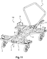
- the frame consists of two parallel tubes A coming to be welded on two parallel tubes B and two tubes C perpendicular to the tubes A, the association of these 6 tubes forming an H-shaped structure and corresponds to the embodiment of the rolling base 100 illustrated on figure 11 .
- Four tubes E come to be welded perpendicular to the two tubes D and A.
- Two tubes F come to be welded perpendicularly to the 2 tubes A.
- the length of the tubes A defines the length of the rolling base 1, 100 and consequently the length of the tubes D.
- the width of the rolling base 1, 100 is defined by the length of the tubes B and C and consequently impacts the length of the four tubes E.
- the absence of the tubes D and E makes it possible to create a rolling base with double notches as illustrated in the figure 11 .
- First rectangular plates 18 provided with holes are welded to the four corners of the frame 11 and partially constitute an upper face of the frame 11.
- Each of the plates 18 is welded to the tubes B and C.
- At the four corners of said frame 11 are also welded second plates 19 partially constituting a lower face of the frame 11.
- each of these plates 19 is welded to the tubes B and C.
- each first plate 18 is found in line with a second plate 19 by being placed above it.
- Two third plates 20 are welded to the tubes E and two third plates 20 are welded to the tubes B and C and partially constitute a lower face of the frame 11.
- the reinforcing webs of the plates 20 welded to the tubes E are also welded to. the tubes E.
- the reinforcing webs of the plates 20 welded to the tubes B and C are welded to the tubes B and C.
- the veil H of the plate 20 which itself is welded to the tubes B and C is welded to the tubes A and the veil I of the plate 20 which is welded to the two tubes B and C is him welded on the tubes A.
- the whole of the frame 2 of the rolling base 1 consists of a single type of tube and of 1 single sheet thickness.
- the push bar 4 which is used to maneuver the rolling base 1 manually and ergonomically, is tubular and is welded to a support plate 22, which is intended to be fixed by screwing on one of the outer tubes 12 of the frame 2.
- the push bar 4 is composed of a single bent tube, so as to form an open loop. The two ends 24, 25 of this loop are welded to the plate 22.
- the push bar 4 is galvanized. It allows the operator, by virtue of its shape in the lower part, to leave the space necessary for lowering the drawbar 5 using the foot, without having to lower himself. Its forward camber allows the operator to manipulate the rolling base 1 by the push bar 4, while keeping a safe passage of the hand with respect to the packaging placed on the rolling base 1.
- the curved tube which makes up the push bar 4 comprises in the upper part two oblique half arms 23 meeting in the center at a height greater than that of the lateral ends. This shape makes it easier for an operator to pick up the push bar at the height that suits him best, regardless of his size.
- the drawbar 5 which is used to attach two rolling bases 1 or to attach a rolling base to a tractor, is taken directly from an already existing drawbar.
- the drawbar 5 has a support plate 26, and the width of said drawbar 5 and said support plate 26 leaves the possibility of passing a hooking interface for a pusher shooter, which is an equipment helping handling when the effort required for moving the rolling base is greater than 17 DAN.
- This drawbar 5 is equipped with a spring 27 allowing it, in the unhitched position, to go up perpendicularly to the frame 2 in order to limit the overall size, and the risk for the operator to come up against it.
- the drawbar 5 is equipped with a buffer to limit its stroke in the low position and a buffer to limit its stroke in vertical position.
- the entire drawbar 5, comprising the spring 27 and the support plate 26 is electro-galvanized. It is either fixed on a tube C or D depending on the direction of traction desired.
- the manual hitch 6 which allows two bases 1 to be hooked together with manual locking, consists of a movable axis 28 in a tube 29. Lights positioned on the tube 29 make it possible to immobilize the axis 28 in the upper part or in the lower part.
- the whole is intended to be fixed by screwing using two plates 30, 31 at the rear of the frame 2 on an external tube C but it can be, depending on the direction of traction desired, be fixed on a tube D thereof. this.
- the whole of this manual coupling is electro-galvanized.
- the idea is to keep the drawbar 5 of the base 1 rolling in the axis of the tubes of the frame 2, to have a better behavior and a better resistance of the materials during the operations of acceleration and braking of a train of bases. 1, while avoiding the risk of stalling.
- the hitch at the foot 7 also makes it possible to hook two rolling bases 1 together, but only with the foot without putting your hands there.
- It consists of a pin 32 welded to two plates 33, one of which is not visible in the figure.
- the assembly formed by the axis 32 and the two plates 33 is intended to be screwed onto the frame 2 of the rolling base 1.
- It is electro-galvanized.
- a “hoe” system in other words “gravity pivot”, makes it possible to lock the drawbar 5 in the high position in order to keep the drawbar 5 in the axis of the frame 2, as for the hand hooking.
- the system is gravity and without fluid control.
- a single press of the foot allows the drawbar 5 to be released by tilting the "hoe” and lowering the drawbar 5 under the anchor pin.
- the outlets 9, which make it possible to locate the goods to be conveyed on the rolling base 1, are parts having two faces 35, 36 substantially at right angles. They are removable and made of sheet metal. They are intended to be fixed by four bolts to the first plates 18 of the frame 2. They can therefore be positioned at different locations on said plates 18, due to the large number of holes present on said plates 18. These outlets 9 are galvanized.
- the extension 8 is tubular and made of sheet metal. It is galvanized and fixed to the frame 2 by screwing. It enables large rolling bases 1 to improve the angle of turn.
- the push bar 4 being fixed to the drawbar support 5 shifts by the value of the extension 8.
- the objective being to remain ergonomic for the operator, ie. ie keep the same distance of the operator from the push bar 4. It can also allow the use of accessories such as a turntable, while keeping the loads in a central position, as it moves the push bar away 4 and frees up the space necessary for the rotation of the plate.
- This extension 8 forms a rectangular frame, one side 37 of which is welded to a support plate 38. The extension 8 is thus fixed to the frame 2 by screwing, via said support plate 38.
- each anti-tilt device 10 is a one-piece bent tube.
- the free ends of the bent tube are each extended by a flat support plate 41, the plane of which is perpendicular to the straight parts of the bent tube.
- Each anti-tipper 10 is fixed by screwing to a second plate 19 of the frame 2, via the two support plates 41 which come into contact with said plates 19. Once mounted on the frame, the rounded segment 40 of each anti-tipper 10 is able to come into contact with the ground.
- the anti-tilters 10 are used to prevent the rolling base 1 from tilting in the case of a configuration with four wheels 3, arranged in a diamond pattern.
- Each anti-tilt device 10 is also galvanized.
- rollers 3 are mounted on the third plates 20 of the frame 2 by means of roller wedges 42, which serve as an interface between said frame 2 and a plate 43 for fixing the roller 3 when the rolling base 1 has four 3 casters arranged in a diamond pattern or have six casters 3.
- the objective is to create a vertical offset on the fixed casters 3 in order to generate a rocking effect allowing better maneuverability.
- the wedges 42 of rollers 3 are also galvanized.
Landscapes
- Engineering & Computer Science (AREA)
- Chemical & Material Sciences (AREA)
- Combustion & Propulsion (AREA)
- Transportation (AREA)
- Mechanical Engineering (AREA)
- Handcart (AREA)
- Road Paving Structures (AREA)
Description
- L'invention se rapporte à une base roulante modulable et capacitaire.
- Une base roulante est généralement utilisée dans une installation industrielle ou un atelier pour convoyer des pièces ou marchandises d'un poste à un autre. Les bases roulantes existantes comportent généralement un châssis avec des roues en partie inférieure, une barre de manœuvre à l'une de leurs extrémités, et des moyens d'attelage. Ces moyens d'attelage peuvent par exemple être constitués d'un timon relevable possédant en extrémité un anneau ou un boitier pour coopérer avec un moyen d'attelage correspondant, qui est un doigt vertical, un crochet ou une sphère.
- A titre d'exemple, la demande de brevet
EP2687429 décrit une base roulante possédant un plateau supérieur monté en rotation sur un châssis autour d'un axe vertical, et des roues disposées en losange. La spécificité de cette base roulante est qu'elle possède un timon relevable doté d'une platine, et le châssis comporte des moyens de fixation particuliers de cette platine et/ou d'une entretoise interposée de façon démontable entre ledit châssis et ladite platine. L'entretoise a pour but de déporter l'attache du timon au châssis, de sorte que dans son état relevé le timon ne vienne pas interférer avec le coin du plateau tournant lorsque ce dernier est manœuvré en rotation par un opérateur. Néanmoins, une telle base roulante présente l'inconvénient d'être figée, et donc de ne pas pouvoir s'adapter facilement et rapidement à une configuration particulière de pièces et/ou de marchandises à transporter. - Le document
GB2190895 - Le document
DE202013100611 U1 divulgue un chariot de transport comprenant un châssis sur lequel sont fixées des roues. Ce document pose un problème de maniabilité. - Une base roulante selon l'invention possède des caractéristiques structurelles lui permettant d'être montée de façon souple, pour pouvoir s'adapter à une grande variété de pièces, d'emballages et/ou de marchandises à transporter, ainsi qu'à une configuration particulière d'atelier ou d'installation industrielle.
- Les notions de « supérieur », « inférieur » ou « vertical » doivent être considérées comme si la base roulante était montée et posée sur le sol.
- L'invention a pour objet une base roulante dotée d'un châssis comprenant des tubes et des plaques.
- La principale caractéristique d'une base roulante selon l'invention est que lesdits tubes et lesdites plaques sont soudés et sont percés de trous pour permettre une fixation par vissage de plusieurs éléments parmi lesquels un timon, une barre de poussée, un attelage manuel ou un attelage au pied, au moins un avaloir, au moins un anti-basculeur, une rallonge et au moins une cale de roulette. Autrement dit, les différents éléments constitutifs d'une base roulante selon l'invention, viennent se fixer par vissage sur le châssis, qui constitue l'élément principal de ladite base roulante. De cette manière, puisqu'un vissage est une technique de fixation qui est réversible, chacun desdits éléments peut être démonté et remonté à tout moment. Une telle base roulante peut ainsi être facilement transportée en étant démontée, puis être montée sur place, au dernier moment. Le châssis joue le rôle d'une plateforme adaptable en dimensions, notamment au niveau de la longueur et de la largeur, sur laquelle les éléments viennent se monter de façon réversible. En possédant des éléments démontables, une base roulante selon l'invention présente un caractère de grande modularité, car il demeure possible de venir fixer au châssis plusieurs versions d'un même élément. Il est important de signaler que le châssis possède généralement une forme simple, soit carrée soit rectangulaire, soit échancrée, et qu'il est très facile à fabriquer par soudage. Il est donc aisé de concevoir quelques modèles de châssis particuliers, en termes de forme et de dimensions, pour pouvoir répondre à une multiplicité de besoins au niveau des marchandises à convoyer, car les différents éléments aptes à venir se fixer sur ces châssis multiplient les différentes configurations de bases roulantes disponibles. La liste des éléments venant se fixer sur le châssis n'est pas exhaustive et peut intégrer des pièces supplémentaires servant ponctuellement, à répondre à un besoin particulier.
- Avantageusement, les trous sont en surnombre sur le châssis par rapport au nombre d'éléments à fixer, permettant à au moins certains desdits éléments d'être fixés à au moins deux emplacements différents sur ledit châssis. Cette caractéristique du châssis accentue encore le caractère modulable d'une base roulante selon l'invention, en permettant à certains éléments d'être fixés à différents endroits dudit châssis. A titre d'exemple, la base roulante peut posséder un châssis rectangulaire et quatre roulettes pouvant, par exemple, être disposées en losange sur le châssis ou être disposées aux quatre coins dudit châssis. Il est également possible de mettre six roulettes sur un même châssis. Une telle configuration de base roulante pourrait être assimilable à un jeu de montage, pour lequel une pièce centrale serait percée d'une multitude de trous, et sur laquelle viendraient se fixer par vissage différents éléments pour aboutir au final à des objets de nature différente.
- De façon préférentielle, le châssis est galvanisé afin d'éviter les risques de corrosion. Puisque la base roulante est amenée à être utilisée à l'intérieur ou à l'extérieur d'une installation ou d'un atelier, il est important de la protéger contre la corrosion qui pourrait dégrader la qualité de sa structure.
- Préférentiellement, le châssis est délimité par quatre tubes externes définissant un cadre rectangulaire, des plaques étant soudées aux quatre coins du cadre pour la fixation des avaloirs et des anti-basculeurs. Le terme rectangulaire couvre la configuration « carrée ».
- De façon avantageuse, une plaque est soudée au niveau d'une zone centrale et inférieure de chaque tube externe pour la fixation des cales de roulettes. Cette configuration du châssis favorise la fixation de roulettes en losange et en configuration six roulettes.
- Avantageusement, la barre de poussée est soudée à une platine support, qui est vissée sur le châssis.
- De façon préférentielle, la barre de poussée est galvanisée.
- Préférentiellement, le timon est soudé à une platine support qui est vissée sur le châssis.
- De façon avantageuse, le timon est galvanisé.
- Avantageusement, la rallonge est constituée par un cadre tubulaire galvanisé qui est destiné à être inséré entre la barre de poussée et le châssis.
- Une base roulante selon l'invention présente un caractère de grande modularité octroyé à la fois par la possibilité de concevoir facilement et rapidement quelques modèles de châssis particuliers, et par les multiples configurations de montage des différents éléments constitutifs de la base roulante, sur un même châssis. Elle a donc l'avantage de se décliner en un très grand nombre de versions pour pouvoir répondre à n'importe quel type de besoin lié à la manutention et au transport de pièces au sein d'un atelier. Elle présente enfin l'avantage de pouvoir être transportée facilement en étant démontée, et d'être montée au dernier moment dans une configuration particulière, en fonction des besoins rencontrés sur place au sein d'un atelier ou d'une installation particulière.
- On donne ci-après, une description détaillée d'un mode de réalisation préféré d'une base roulante selon l'invention, en se référant aux figures suivantes :
- La
figure 1A est une vue en perspective d'une base roulante, selon l'invention, - La
figure 1B est une vue en perspective éclatée de la base roulante de lafigure 1A , - La
figure 2A est une vue en perspective sous un autre angle de la base roulante de lafigure 1A , - La
figure 2B est une vue en perspective éclatée de la base roulante de lafigure 2A , - La
figure 3 est une vue en perspective éclatée d'un châssis d'une base roulante selon l'invention, - La
figure 4 est une vue en perspective d'une barre de poussée d'une base roulante selon l'invention, - La
figure 5 est une vue en perspective d'un timon d'une base roulante selon l'invention, - La
figure 6 est une vue en perspective d'un attelage manuel d'une base roulante selon l'invention, - La
figure 7 est une vue en perspective d'un attelage au pied d'une base roulante selon l'invention, - La
figure 8 est une vue en perspective d'un avaloir d'une base roulante selon l'invention, - La
figure 9 est une vue en perspective d'une rallonge d'une base roulante selon l'invention, - La
figure 10 est une vue en perspective d'un anti-basculeur d'une base roulante selon l'invention, - La
figure 11 est une vue en perspective d'un autre mode de réalisation d'une base roulante selon l'invention. - En se référant aux
figures 1A, 1B ,2A et 2B une base roulante 1 selon l'invention comprend un châssis 2 de forme carrée, sur lequel sont montés par vissage tous les éléments constitutifs d'une telle base roulante 1. Ces éléments comprennent de façon non exhaustive, des roulettes 3, une barre de poussée 4, un timon 5, un attelage manuel 6 ou un attelage de pied 7, une rallonge 8, des avaloirs 9 et des anti-basculeurs 10. Le châssis 2 agit ainsi comme une plateforme centrale sur laquelle seront entreposées des pièces ou des marchandises à transporter, et sur laquelle viennent se monter par vissage les différents éléments de la base roulante 1. En se référant à lafigure 11 , selon un autre mode de réalisation préféré, la base roulante 100 peut également être échancrée en forme de H, par un simple retrait de certains tubes constituant la base roulante mentionnée ci-dessus. - Une fois que la base roulante a été montée, comme le montrent les
figures 1A ,2A ,11 un cariste dépose sur le châssis 2 les pièces et/ou les marchandises à convoyer. Un tractoriste peut accrocher la ou les bases roulantes et les déplacer d'un point à un autre à l'aide d'un tracteur. Une fois arrivé au point d'acheminement, le tractoriste se saisit ensuite de la barre de poussée 4 pour exercer un effort de poussée ou de traction afin de déplacer la base roulante par l'intermédiaire des roulettes 3, dont certaines sont mobiles en rotation. De cette manière, le tractoriste peut déplacer la base roulante 1 à sa convenance, pour notamment la positionner au poste de travail dans le sens souhaité. - En se référant aux
figures 2B et3 , le châssis 2 est constitué par un cadre 11 de forme carrée, comprenant des tubes et des plaques soudés. Le cadre 11 est galvanisé afin de limiter les risques de corrosion dans le cas d'une utilisation externe. Il possède des découpes laser afin de faciliter les posages pour la soudure, et gagner du temps en réalisation. Plus précisément, le cadre est constitué de deux tubes parallèles A venant se souder sur deux tubes parallèles B et deux tubes C perpendiculairement aux tubes A, l'association de ces 6 tubes formant une structure en forme de H et correspond au mode de réalisation de la base roulante 100 illustrée à lafigure 11 . Quatre tubes E viennent se souder perpendiculairement aux deux tubes D et A. Deux tubes F viennent se souder perpendiculairement aux 2 tubes A. La longueur des tubes A définit la longueur de la base roulante 1, 100 et par conséquent la longueur des tubes D. La largeur de la base roulante 1, 100 est définie par la longueur des tubes B et C et par conséquent impacte la longueur des quatre tubes E. L'absence des tubes D et E permet de créer une base roulante à double échancrures comme illustré à lafigure 11 . En ne soudant pas d'un côté seulement deux tubes E et un tube D, on créé une base roulante a simple échancrure. Des premières plaques 18 rectangulaires et dotées de trous sont soudées aux quatre coins du cadre 11 et constituent partiellement une face supérieure du cadre 11. Chacune des plaques 18 est soudée sur les tubes B et C. Aux quatre coins dudit cadre 11 sont également soudées des deuxièmes plaques 19 constituant partiellement une face inférieure du cadre 11.Chacune de ces plaques 19 est soudée sur les tubes B et C. De cette manière, au sein de la base roulante 1, chaque première plaque 18 se retrouve au droit d'une deuxième plaque 19 en étant placée au dessus de celle-ci. Deux troisièmes plaques 20 sont soudées sur les tubes E et deux troisièmes plaques 20 sont soudées sur les tubes B et C et constituent partiellement une face inférieure du cadre 11. Les voiles de renfort des plaques 20 soudées sur les tubes E sont eux aussi soudés sur les tubes E. Les voiles de renfort des plaques 20 soudées sur les tubes B et C sont soudés sur les tubes B et C. Le voile H de la plaque 20 qui elle-même est soudée sur les tubes B et C est soudé sur les tubes A et le voile I de la plaque 20 qui est soudée sur les deux tubes B et C est lui soudé sur les tubes A. Il faut noter que l'ensemble du cadre 2 de la base roulante 1 est constituée d'un seul type de tube et de 1 seule épaisseur de tôle. - En se référant à la
figure 4 , la barre de poussée 4, qui sert à manœuvrer la base roulante 1 manuellement et ergonomiquement, est tubulaire et est soudée à une platine support 22, qui est destinée à être fixée par vissage sur l'un des tubes externes 12 du châssis 2. La barre de poussée 4 est composée d'un seul tube cintré, de manière à former une boucle ouverte. Les deux extrémités 24, 25 de cette boucle sont soudées à la platine 22. La barre de poussée 4 est galvanisée. Elle permet à l'opérateur, de par sa forme en partie basse, de laisser l'espace nécessaire pour baisser le timon 5 à l'aide du pied, sans avoir à se baisser. Sa cambrure vers l'avant permet à l'opérateur de manipuler la base roulante 1 par la barre de poussée 4, tout en gardant un passage de main sécurisé par rapport à l'emballage posé sur la base roulante 1. Avantageusement, le tube cintré qui compose la barre de poussée 4, comporte en partie supérieure deux demi bras 23 obliques se rejoignant au centre à une hauteur supérieure à celle des extrémités latérales. Cette forme facilite la prise de la barre de poussée par un opérateur à la hauteur qui lui convient le mieux, indépendamment de sa taille. - En se référant à la
figure 5 , le timon 5, qui sert à accrocher deux bases roulantes 1 ou à accrocher une base roulante à un tracteur, est directement repris d'un timon déjà existant. Le timon 5 possède une plaque support 26, et la largeur dudit timon 5 et de ladite plaque support 26 laisse la possibilité de passer une interface d'accrochage pour un tireur pousseur, qui est un équipement aidant à la manutention quand l'effort requis pour déplacer la base roulante est supérieur à 17 DAN. Ce timon 5 est équipé d'un ressort 27 lui permettant, en position non attelé, de remonter perpendiculairement au châssis 2 afin de limiter l'encombrement hors tout, et le risque pour l'opérateur de buter dans celui-ci. Le timon 5 est équipé d'un tampon permettant de limiter sa course en position basse et d'un tampon limitant sa course en position verticale. L'ensemble du timon 5, comprenant le ressort 27 et la plaque support 26 est électro-zingué. Il est soit fixé sur un tube C ou D suivant le sens de traction souhaité. - En se référant à la
figure 6 , l'attelage manuel 6, qui permet d'accrocher deux bases 1 entre elles avec un verrouillage manuel, est constitué d'un axe mobile 28 dans un tube 29. Des lumières positionnées sur le tube 29 permettent d'immobiliser l'axe 28 en partie haute ou en partie basse. Le tout est destiné à être fixé par vissage à l'aide de deux plaques 30, 31 à l'arrière du châssis 2 sur un tube externe C mais il peut être suivant le sens de traction souhaité être fixé sur un tube D de celui-ci. L'ensemble de cet attelage manuel est électro-zingué. L'idée est de garder le timon 5 de la base 1 roulante dans l'axe des tubes du châssis 2, pour avoir un meilleur comportement et une meilleure résistance des matériaux pendant les opérations d'accélération et de freinage d'un train de bases roulantes 1, tout en évitant le risque de décrochage. - En se référant à la
figure 7 , l'attelage au pied 7 permet également d'accrocher deux bases 1 roulantes entre elles, mais uniquement avec le pied sans y mettre les mains. Il est constitué d'un axe 32 soudé sur deux plaques 33 dont l'une n'est pas visible sur la figure. L'ensemble constitué par l'axe 32 et les deux plaques 33 est destiné à être vissé sur le châssis 2 de la base roulante 1. Il est électro-zingué. Un système de « binette », en d'autres termes de « pivot gravitaires », permet de verrouiller le timon 5 en position haute afin de garder le timon 5 dans l'axe du châssis 2, comme pour l'accrochage main. Le système est gravitaire et sans pilotage par un fluide. Un seul appui du pied permet de décrocher le timon 5 en faisant basculer la « binette » et en baissant le timon 5 sous le pion d'ancrage. - En se référant à la
figure 8 , les avaloirs 9, qui permettent de localiser les marchandises à convoyer sur la base roulante 1, sont des pièces présentant deux faces 35, 36 sensiblement à angle droit. Ils sont démontables et en tôle. Ils sont destinés à être fixés par quatre boulons aux premières plaques 18 du châssis 2. Ils peuvent donc être positionnés à différents endroits sur lesdites plaques 18, en raison du grand nombre de trous présents sur lesdites plaques 18. Ces avaloirs 9 sont galvanisés. - En se référant à la
figure 9 , la rallonge 8 est tubulaire et en tôle. Elle est galvanisée et fixée au châssis 2 par vissage. Elle permet aux bases roulantes 1 de grandes dimensions d'améliorer l'angle de giration. Quand la base 1 roulante est utilisée avec une rallonge 8, la barre de poussée 4 étant fixée sur le support timon 5 se décale de la valeur de la rallonge 8. L'objectif étant de rester ergonomique pour l'opérateur, c'est-à-dire garder le même éloignement de l'opérateur par rapport à la barre de poussée 4. Elle peut aussi permettre d'utiliser des accessoires comme un plateau tournant, tout en gardant les charges en position centrale, car elle éloigne la barre de poussée 4 et libère de l'espace nécessaire à la rotation du plateau. Cette rallonge 8 forme un cadre rectangulaire dont un coté 37 est soudé à une plaque support 38. La rallonge 8 est ainsi fixée au châssis 2 par vissage, via ladite plaque support 38. - En se référant à la
figure 10 , chaque anti-basculeur 10 est un tube cintré monobloc. Les extrémités libres du tube cintré sont prolongées chacune par une plaque support 41 plane, dont le plan est perpendiculaire aux parties droites du tube cintré. Chaque anti-basculeur 10 est fixé par vissage à une deuxième plaque 19 du châssis 2, via les deux plaques support 41 qui viennent au contact desdites plaques 19. Une fois monté sur le châssis, le segment arrondi 40 de chaque anti-basculeur 10 est apte à venir au contact du sol. Les anti-basculeurs 10 servent à éviter le basculement de la base roulante 1 dans le cas d'une configuration à quatre roulettes 3, disposées en losange. Chaque anti-basculeur 10 est aussi galvanisé. - En se référant aux
figures 1B et2B , les roulettes 3 sont montées sur les troisièmes plaques 20 du châssis 2 par l'intermédiaire de cales 42 de roulettes, qui servent d'interface entre ledit châssis 2 et une platine 43 de fixation de la roulette 3 lorsque la base roulante 1 possède quatre roulettes 3 disposées en losange ou possèdent six roulettes 3. L'objectif est de créer un décalage vertical sur les roulettes 3 fixes afin de générer un effet de bascule permettant une meilleure manœuvrabilité. Les cales 42 de roulettes 3 sont elles aussi galvanisées. - Suivant les différents types de base roulante utilisée, les roulettes 3 sont différentes :
- Les bases roulantes 1 ayant des roulettes 3 au coin, ou échancrées, sont équipées de deux roulettes 3 suspendues et fixes du côté opposé à la barre de poussée 4 et de deux roulettes suspendues et pivotantes coté barre de poussée 4.
- Les bases roulantes 1 ayant des roulettes 3 disposées en losange sont équipées de deux roulettes 3 suspendues et fixes pour les roulettes 3 positionnées dans l'axe central avec décalage en Z, d'une roulette 3 suspendue et pivotante à l'avant et d'une roulette 3 suspendue pivotante, détarée à débattement libre à l'arrière avec décalage en Z.
- Les bases roulantes équipées de six roulettes 3 sont équipées de quatre roulettes 3 suspendues et pivotantes positionnées dans les angles de la base roulante 1. Les deux roulettes 3 côté opposé à la barre de poussée 4, sont détarées et à débattement libre avec décalage en Z. Les roulettes 3 situées dans l'axe de la base roulante 1 sont suspendues et fixe. De par sa conception, la base roulante 1 peut accepter jusqu'à 1500 kg de marchandises pour les bases roulantes 1 avec des roulettes disposées en losange, et 2000 kg pour les bases roulantes avec des roulettes disposées en carré ou en configuration six roues.
Claims (10)
- Base roulante (1) dotée d'un châssis (2) comprenant des tubes (A, B, C, D, E, F, G) et des plaques (18, 19, 20), soudés et percés de trous permettant une fixation par vissage de plusieurs éléments parmi lesquels un timon (5), une barre de poussée (4), un attelage manuel (6) ou un attelage au pied (7), au moins un avaloir (9), au moins un anti-basculeur (10), une rallonge (8) et au moins une cale (42) de roulette, caractérisé en ce qu'elle comprend :- le timon (5) équipé d'un ressort (27) lui permettant en position non attelé de remonter perpendiculairement au châssis (2), et- la barre de poussée (4) composée d'un seul tube cintré de forme de boucle ouverte en partie basse qui laisse un espace nécessaire pour baisser le timon (5), et qui comporte en partie supérieure deux demi bras (23) obliques se rejoignant au centre à une hauteur supérieure à celle des extrémités latérales.
- Base roulante selon la revendication 1, caractérisé en ce que les trous sont en surnombre sur le châssis (2) par rapport au nombre d'éléments à fixer, permettant à au moins certains desdits éléments d'être fixés à au moins deux emplacements différents sur ledit châssis (2).
- Base roulante selon l'une quelconque des revendications 1 à 2, caractérisé en ce que le châssis est galvanisé afin d'éviter les risques de corrosion.
- Base roulante selon l'une quelconque des revendications 1 à 3, caractérisée en ce que le châssis (2) est délimité par quatre tubes externes (C, D) définissant un cadre (11) rectangulaire, et en ce que des plaques (18, 19) sont soudées aux quatre coins du cadre (11) aux tubes (B, C) et sur lesquelles sont fixés des avaloirs (9) et/ou des anti-basculeurs (10).
- Base roulante selon la revendication 4, caractérisée en ce qu'une plaque (20) est soudée au niveau d'une zone centrale et inférieure de chaque tube externe (C, D), sur laquelle sont fixées des cales (42) de roulettes (3).
- Base roulante selon l'une quelconque des revendications 1 à 5, caractérisée en ce que la barre de poussée (4) est soudée à une platine support (22), qui est vissée sur le châssis (2).
- Base roulante selon l'une quelconque des revendications 1 à 6, caractérisée en ce que la barre de poussée (4) est galvanisée.
- Base roulante selon l'une quelconque des revendications 1 à 7, caractérisée en ce que le timon (5) est soudé à une platine support (26) qui est vissée sur le châssis (2).
- Base roulante selon l'une quelconque des revendications 1 à 8, caractérisée en ce que le timon (5) est galvanisé.
- Base roulante selon l'une quelconque des revendications 1 à 9, caractérisée en ce que la rallonge (8) est constituée par un cadre tubulaire galvanisé inséré entre la barre de poussée (4) et le châssis (2).
Priority Applications (1)
| Application Number | Priority Date | Filing Date | Title |
|---|---|---|---|
| EP17172504.7A EP3257720B1 (fr) | 2016-06-17 | 2017-05-23 | Base de transport roulante et modulable |
Applications Claiming Priority (2)
| Application Number | Priority Date | Filing Date | Title |
|---|---|---|---|
| FR1655667A FR3052734B1 (fr) | 2016-06-17 | 2016-06-17 | Base roulante modulable et capacitaire |
| EP17172504.7A EP3257720B1 (fr) | 2016-06-17 | 2017-05-23 | Base de transport roulante et modulable |
Publications (2)
| Publication Number | Publication Date |
|---|---|
| EP3257720A1 EP3257720A1 (fr) | 2017-12-20 |
| EP3257720B1 true EP3257720B1 (fr) | 2021-10-06 |
Family
ID=56842891
Family Applications (1)
| Application Number | Title | Priority Date | Filing Date |
|---|---|---|---|
| EP17172504.7A Active EP3257720B1 (fr) | 2016-06-17 | 2017-05-23 | Base de transport roulante et modulable |
Country Status (3)
| Country | Link |
|---|---|
| EP (1) | EP3257720B1 (fr) |
| ES (1) | ES2900745T3 (fr) |
| FR (1) | FR3052734B1 (fr) |
Families Citing this family (5)
| Publication number | Priority date | Publication date | Assignee | Title |
|---|---|---|---|---|
| CN108275174B (zh) * | 2018-01-08 | 2020-01-17 | 江苏科趣新材料科技有限公司 | 一种塑料制品运输装置 |
| HUE068543T2 (hu) * | 2018-07-23 | 2025-01-28 | Pietro Laudani | Kétirányú targonca |
| CN111114608A (zh) * | 2020-02-12 | 2020-05-08 | 泉州卓烨脚轮制造有限公司 | 一种推车 |
| FR3114791B1 (fr) * | 2020-10-06 | 2022-10-07 | Vignal Systems | Chariot de transport d’objets |
| CN114362024A (zh) * | 2022-01-22 | 2022-04-15 | 国网福建省电力有限公司 | 手车式开关柜的防倾倒手车 |
Family Cites Families (7)
| Publication number | Priority date | Publication date | Assignee | Title |
|---|---|---|---|---|
| GB2008064B (en) * | 1977-11-15 | 1982-04-15 | Twil Handling Systems Ltd | Load carrying pallets |
| GB2190895B (en) * | 1986-05-22 | 1989-12-20 | Clares Equip Ltd | Interengageable wheeled pallet |
| DE202012104418U1 (de) * | 2012-11-16 | 2013-01-24 | Karl Miller Gmbh & Co. Kg | Transporteinrichtung |
| FR2993228B3 (fr) * | 2012-07-16 | 2015-01-16 | Coutier Ind | Base roulante et pivotante horizontalement |
| FR2993229B3 (fr) * | 2012-07-16 | 2015-01-16 | Coutier Ind | Base roulante a plateau tournant |
| DE202013100611U1 (de) * | 2013-02-11 | 2013-03-27 | Markus Lietz | Transportwagen |
| CN204502330U (zh) * | 2015-01-12 | 2015-07-29 | 东莞新峰塑胶电器制品有限公司 | 高尔夫球袋手推车 |
-
2016
- 2016-06-17 FR FR1655667A patent/FR3052734B1/fr not_active Expired - Fee Related
-
2017
- 2017-05-23 ES ES17172504T patent/ES2900745T3/es active Active
- 2017-05-23 EP EP17172504.7A patent/EP3257720B1/fr active Active
Non-Patent Citations (1)
| Title |
|---|
| None * |
Also Published As
| Publication number | Publication date |
|---|---|
| FR3052734B1 (fr) | 2019-01-25 |
| FR3052734A1 (fr) | 2017-12-22 |
| EP3257720A1 (fr) | 2017-12-20 |
| ES2900745T3 (es) | 2022-03-18 |
Similar Documents
| Publication | Publication Date | Title |
|---|---|---|
| EP3257720A1 (fr) | Base de transport roulante et modulable | |
| FR2949217A1 (fr) | Cale pour camion et son moyen de logement | |
| FR2666553A1 (fr) | Chariot equipe d'une partie de reception de marchandises reliee a un coulisseau mobile en hauteur, et dispositif de guidage pour ce coulisseau. | |
| EP3377397B1 (fr) | Véhicule de transport d'une charge | |
| EP3215692B1 (fr) | Piètement roulant pour un mât télescopique d'un appareil de levage de plaques, appareil muni d'un tel piètement, et procédé de mise en oeuvre | |
| EP3585631B1 (fr) | Module logistique roulant muni d'un dispositif d'attelage | |
| FR2824783A1 (fr) | Chariot de manutention | |
| EP2946994B1 (fr) | Remorque pour véhicule à deux roues | |
| FR3102781A1 (fr) | Equipement d’ascension sécurisé pour travaux sur banches | |
| EP1270482A1 (fr) | Support-devidoir de touret equipe d'un système de levage | |
| FR3114791A1 (fr) | Chariot de transport d’objets | |
| EP2097306B1 (fr) | Chariot de service de chambre pour les hôtels | |
| FR3024393A1 (fr) | Unite de roulage, element mobile la comportant et ensemble de tels elements mobiles | |
| FR2789661A1 (fr) | Chassis de stockage pour bonbonnes de liquide et notamment pour bonbonnes a eau | |
| FR2490173A1 (fr) | Chariot pour le transport et la distribution de documents | |
| EP1762279A1 (fr) | Equipement de golf comprenant un sac de golf et un chariot de support de celui-ci | |
| EP0896935A1 (fr) | Dispositif de stockage de futs | |
| EP3479193B1 (fr) | Système de répartition de charge au sol pour armoire informatique | |
| WO2006010847A1 (fr) | Dispositif et ensemble de stockage de recipients de liquide | |
| FR2528817A1 (fr) | Dispositif de levage de plaque | |
| FR3029159A1 (fr) | Chariot de manutention d'un ensemble d'objets sous forme de plaques et ensemble le comportant | |
| BE463386A (fr) | ||
| FR2789959A1 (fr) | Chariot emboitable de constitution simple et robuste, notamment adapte a recevoir des objets volumineux | |
| FR3089477A1 (fr) | Diable | |
| FR2956095A3 (fr) | Equipement de stockage et de manipulation pour recipients en general |
Legal Events
| Date | Code | Title | Description |
|---|---|---|---|
| PUAI | Public reference made under article 153(3) epc to a published international application that has entered the european phase |
Free format text: ORIGINAL CODE: 0009012 |
|
| STAA | Information on the status of an ep patent application or granted ep patent |
Free format text: STATUS: THE APPLICATION HAS BEEN PUBLISHED |
|
| AK | Designated contracting states |
Kind code of ref document: A1 Designated state(s): AL AT BE BG CH CY CZ DE DK EE ES FI FR GB GR HR HU IE IS IT LI LT LU LV MC MK MT NL NO PL PT RO RS SE SI SK SM TR |
|
| AX | Request for extension of the european patent |
Extension state: BA ME |
|
| STAA | Information on the status of an ep patent application or granted ep patent |
Free format text: STATUS: REQUEST FOR EXAMINATION WAS MADE |
|
| 17P | Request for examination filed |
Effective date: 20180320 |
|
| RBV | Designated contracting states (corrected) |
Designated state(s): AL AT BE BG CH CY CZ DE DK EE ES FI FR GB GR HR HU IE IS IT LI LT LU LV MC MK MT NL NO PL PT RO RS SE SI SK SM TR |
|
| STAA | Information on the status of an ep patent application or granted ep patent |
Free format text: STATUS: EXAMINATION IS IN PROGRESS |
|
| 17Q | First examination report despatched |
Effective date: 20181210 |
|
| GRAP | Despatch of communication of intention to grant a patent |
Free format text: ORIGINAL CODE: EPIDOSNIGR1 |
|
| STAA | Information on the status of an ep patent application or granted ep patent |
Free format text: STATUS: GRANT OF PATENT IS INTENDED |
|
| INTG | Intention to grant announced |
Effective date: 20210504 |
|
| GRAS | Grant fee paid |
Free format text: ORIGINAL CODE: EPIDOSNIGR3 |
|
| GRAA | (expected) grant |
Free format text: ORIGINAL CODE: 0009210 |
|
| STAA | Information on the status of an ep patent application or granted ep patent |
Free format text: STATUS: THE PATENT HAS BEEN GRANTED |
|
| AK | Designated contracting states |
Kind code of ref document: B1 Designated state(s): AL AT BE BG CH CY CZ DE DK EE ES FI FR GB GR HR HU IE IS IT LI LT LU LV MC MK MT NL NO PL PT RO RS SE SI SK SM TR |
|
| REG | Reference to a national code |
Ref country code: GB Ref legal event code: FG4D Free format text: NOT ENGLISH |
|
| REG | Reference to a national code |
Ref country code: CH Ref legal event code: EP Ref country code: AT Ref legal event code: REF Ref document number: 1435981 Country of ref document: AT Kind code of ref document: T Effective date: 20211015 |
|
| REG | Reference to a national code |
Ref country code: DE Ref legal event code: R096 Ref document number: 602017047045 Country of ref document: DE |
|
| REG | Reference to a national code |
Ref country code: IE Ref legal event code: FG4D Free format text: LANGUAGE OF EP DOCUMENT: FRENCH |
|
| REG | Reference to a national code |
Ref country code: LT Ref legal event code: MG9D |
|
| REG | Reference to a national code |
Ref country code: NL Ref legal event code: MP Effective date: 20211006 |
|
| RAP4 | Party data changed (patent owner data changed or rights of a patent transferred) |
Owner name: RENAULT S.A.S |
|
| REG | Reference to a national code |
Ref country code: AT Ref legal event code: MK05 Ref document number: 1435981 Country of ref document: AT Kind code of ref document: T Effective date: 20211006 |
|
| REG | Reference to a national code |
Ref country code: ES Ref legal event code: FG2A Ref document number: 2900745 Country of ref document: ES Kind code of ref document: T3 Effective date: 20220318 |
|
| PG25 | Lapsed in a contracting state [announced via postgrant information from national office to epo] |
Ref country code: RS Free format text: LAPSE BECAUSE OF FAILURE TO SUBMIT A TRANSLATION OF THE DESCRIPTION OR TO PAY THE FEE WITHIN THE PRESCRIBED TIME-LIMIT Effective date: 20211006 Ref country code: LT Free format text: LAPSE BECAUSE OF FAILURE TO SUBMIT A TRANSLATION OF THE DESCRIPTION OR TO PAY THE FEE WITHIN THE PRESCRIBED TIME-LIMIT Effective date: 20211006 Ref country code: FI Free format text: LAPSE BECAUSE OF FAILURE TO SUBMIT A TRANSLATION OF THE DESCRIPTION OR TO PAY THE FEE WITHIN THE PRESCRIBED TIME-LIMIT Effective date: 20211006 Ref country code: BG Free format text: LAPSE BECAUSE OF FAILURE TO SUBMIT A TRANSLATION OF THE DESCRIPTION OR TO PAY THE FEE WITHIN THE PRESCRIBED TIME-LIMIT Effective date: 20220106 Ref country code: AT Free format text: LAPSE BECAUSE OF FAILURE TO SUBMIT A TRANSLATION OF THE DESCRIPTION OR TO PAY THE FEE WITHIN THE PRESCRIBED TIME-LIMIT Effective date: 20211006 |
|
| PG25 | Lapsed in a contracting state [announced via postgrant information from national office to epo] |
Ref country code: IS Free format text: LAPSE BECAUSE OF FAILURE TO SUBMIT A TRANSLATION OF THE DESCRIPTION OR TO PAY THE FEE WITHIN THE PRESCRIBED TIME-LIMIT Effective date: 20220206 Ref country code: SE Free format text: LAPSE BECAUSE OF FAILURE TO SUBMIT A TRANSLATION OF THE DESCRIPTION OR TO PAY THE FEE WITHIN THE PRESCRIBED TIME-LIMIT Effective date: 20211006 Ref country code: PT Free format text: LAPSE BECAUSE OF FAILURE TO SUBMIT A TRANSLATION OF THE DESCRIPTION OR TO PAY THE FEE WITHIN THE PRESCRIBED TIME-LIMIT Effective date: 20220207 Ref country code: PL Free format text: LAPSE BECAUSE OF FAILURE TO SUBMIT A TRANSLATION OF THE DESCRIPTION OR TO PAY THE FEE WITHIN THE PRESCRIBED TIME-LIMIT Effective date: 20211006 Ref country code: NO Free format text: LAPSE BECAUSE OF FAILURE TO SUBMIT A TRANSLATION OF THE DESCRIPTION OR TO PAY THE FEE WITHIN THE PRESCRIBED TIME-LIMIT Effective date: 20220106 Ref country code: NL Free format text: LAPSE BECAUSE OF FAILURE TO SUBMIT A TRANSLATION OF THE DESCRIPTION OR TO PAY THE FEE WITHIN THE PRESCRIBED TIME-LIMIT Effective date: 20211006 Ref country code: LV Free format text: LAPSE BECAUSE OF FAILURE TO SUBMIT A TRANSLATION OF THE DESCRIPTION OR TO PAY THE FEE WITHIN THE PRESCRIBED TIME-LIMIT Effective date: 20211006 Ref country code: HR Free format text: LAPSE BECAUSE OF FAILURE TO SUBMIT A TRANSLATION OF THE DESCRIPTION OR TO PAY THE FEE WITHIN THE PRESCRIBED TIME-LIMIT Effective date: 20211006 Ref country code: GR Free format text: LAPSE BECAUSE OF FAILURE TO SUBMIT A TRANSLATION OF THE DESCRIPTION OR TO PAY THE FEE WITHIN THE PRESCRIBED TIME-LIMIT Effective date: 20220107 |
|
| REG | Reference to a national code |
Ref country code: DE Ref legal event code: R097 Ref document number: 602017047045 Country of ref document: DE |
|
| RAP4 | Party data changed (patent owner data changed or rights of a patent transferred) |
Owner name: RENAULT S.A.S |
|
| PG25 | Lapsed in a contracting state [announced via postgrant information from national office to epo] |
Ref country code: SM Free format text: LAPSE BECAUSE OF FAILURE TO SUBMIT A TRANSLATION OF THE DESCRIPTION OR TO PAY THE FEE WITHIN THE PRESCRIBED TIME-LIMIT Effective date: 20211006 Ref country code: SK Free format text: LAPSE BECAUSE OF FAILURE TO SUBMIT A TRANSLATION OF THE DESCRIPTION OR TO PAY THE FEE WITHIN THE PRESCRIBED TIME-LIMIT Effective date: 20211006 Ref country code: RO Free format text: LAPSE BECAUSE OF FAILURE TO SUBMIT A TRANSLATION OF THE DESCRIPTION OR TO PAY THE FEE WITHIN THE PRESCRIBED TIME-LIMIT Effective date: 20211006 Ref country code: EE Free format text: LAPSE BECAUSE OF FAILURE TO SUBMIT A TRANSLATION OF THE DESCRIPTION OR TO PAY THE FEE WITHIN THE PRESCRIBED TIME-LIMIT Effective date: 20211006 Ref country code: DK Free format text: LAPSE BECAUSE OF FAILURE TO SUBMIT A TRANSLATION OF THE DESCRIPTION OR TO PAY THE FEE WITHIN THE PRESCRIBED TIME-LIMIT Effective date: 20211006 Ref country code: CZ Free format text: LAPSE BECAUSE OF FAILURE TO SUBMIT A TRANSLATION OF THE DESCRIPTION OR TO PAY THE FEE WITHIN THE PRESCRIBED TIME-LIMIT Effective date: 20211006 |
|
| PLBE | No opposition filed within time limit |
Free format text: ORIGINAL CODE: 0009261 |
|
| STAA | Information on the status of an ep patent application or granted ep patent |
Free format text: STATUS: NO OPPOSITION FILED WITHIN TIME LIMIT |
|
| 26N | No opposition filed |
Effective date: 20220707 |
|
| PG25 | Lapsed in a contracting state [announced via postgrant information from national office to epo] |
Ref country code: AL Free format text: LAPSE BECAUSE OF FAILURE TO SUBMIT A TRANSLATION OF THE DESCRIPTION OR TO PAY THE FEE WITHIN THE PRESCRIBED TIME-LIMIT Effective date: 20211006 |
|
| PG25 | Lapsed in a contracting state [announced via postgrant information from national office to epo] |
Ref country code: SI Free format text: LAPSE BECAUSE OF FAILURE TO SUBMIT A TRANSLATION OF THE DESCRIPTION OR TO PAY THE FEE WITHIN THE PRESCRIBED TIME-LIMIT Effective date: 20211006 |
|
| REG | Reference to a national code |
Ref country code: CH Ref legal event code: PL |
|
| REG | Reference to a national code |
Ref country code: BE Ref legal event code: MM Effective date: 20220531 |
|
| PG25 | Lapsed in a contracting state [announced via postgrant information from national office to epo] |
Ref country code: MC Free format text: LAPSE BECAUSE OF FAILURE TO SUBMIT A TRANSLATION OF THE DESCRIPTION OR TO PAY THE FEE WITHIN THE PRESCRIBED TIME-LIMIT Effective date: 20211006 Ref country code: LU Free format text: LAPSE BECAUSE OF NON-PAYMENT OF DUE FEES Effective date: 20220523 Ref country code: LI Free format text: LAPSE BECAUSE OF NON-PAYMENT OF DUE FEES Effective date: 20220531 Ref country code: CH Free format text: LAPSE BECAUSE OF NON-PAYMENT OF DUE FEES Effective date: 20220531 |
|
| PG25 | Lapsed in a contracting state [announced via postgrant information from national office to epo] |
Ref country code: IE Free format text: LAPSE BECAUSE OF NON-PAYMENT OF DUE FEES Effective date: 20220523 |
|
| PG25 | Lapsed in a contracting state [announced via postgrant information from national office to epo] |
Ref country code: IT Free format text: LAPSE BECAUSE OF FAILURE TO SUBMIT A TRANSLATION OF THE DESCRIPTION OR TO PAY THE FEE WITHIN THE PRESCRIBED TIME-LIMIT Effective date: 20211006 Ref country code: BE Free format text: LAPSE BECAUSE OF NON-PAYMENT OF DUE FEES Effective date: 20220531 |
|
| P01 | Opt-out of the competence of the unified patent court (upc) registered |
Effective date: 20230608 |
|
| PG25 | Lapsed in a contracting state [announced via postgrant information from national office to epo] |
Ref country code: HU Free format text: LAPSE BECAUSE OF FAILURE TO SUBMIT A TRANSLATION OF THE DESCRIPTION OR TO PAY THE FEE WITHIN THE PRESCRIBED TIME-LIMIT; INVALID AB INITIO Effective date: 20170523 |
|
| PG25 | Lapsed in a contracting state [announced via postgrant information from national office to epo] |
Ref country code: MK Free format text: LAPSE BECAUSE OF FAILURE TO SUBMIT A TRANSLATION OF THE DESCRIPTION OR TO PAY THE FEE WITHIN THE PRESCRIBED TIME-LIMIT Effective date: 20211006 Ref country code: CY Free format text: LAPSE BECAUSE OF FAILURE TO SUBMIT A TRANSLATION OF THE DESCRIPTION OR TO PAY THE FEE WITHIN THE PRESCRIBED TIME-LIMIT Effective date: 20211006 |
|
| VS25 | Lapsed in a validation state [announced via postgrant information from nat. office to epo] |
Ref country code: MA Free format text: LAPSE BECAUSE OF FAILURE TO SUBMIT A TRANSLATION OF THE DESCRIPTION OR TO PAY THE FEE WITHIN THE PRESCRIBED TIME-LIMIT Effective date: 20211006 |
|
| PG25 | Lapsed in a contracting state [announced via postgrant information from national office to epo] |
Ref country code: MT Free format text: LAPSE BECAUSE OF FAILURE TO SUBMIT A TRANSLATION OF THE DESCRIPTION OR TO PAY THE FEE WITHIN THE PRESCRIBED TIME-LIMIT Effective date: 20211006 |
|
| PGFP | Annual fee paid to national office [announced via postgrant information from national office to epo] |
Ref country code: DE Payment date: 20250521 Year of fee payment: 9 |
|
| PGFP | Annual fee paid to national office [announced via postgrant information from national office to epo] |
Ref country code: GB Payment date: 20250527 Year of fee payment: 9 Ref country code: ES Payment date: 20250627 Year of fee payment: 9 |
|
| PGFP | Annual fee paid to national office [announced via postgrant information from national office to epo] |
Ref country code: FR Payment date: 20250528 Year of fee payment: 9 |
|
| PG25 | Lapsed in a contracting state [announced via postgrant information from national office to epo] |
Ref country code: TR Free format text: LAPSE BECAUSE OF FAILURE TO SUBMIT A TRANSLATION OF THE DESCRIPTION OR TO PAY THE FEE WITHIN THE PRESCRIBED TIME-LIMIT Effective date: 20211006 |