EP3257984A1 - Garnzuführer mit motorisierter garnwickelspule - Google Patents
Garnzuführer mit motorisierter garnwickelspule Download PDFInfo
- Publication number
- EP3257984A1 EP3257984A1 EP17176106.7A EP17176106A EP3257984A1 EP 3257984 A1 EP3257984 A1 EP 3257984A1 EP 17176106 A EP17176106 A EP 17176106A EP 3257984 A1 EP3257984 A1 EP 3257984A1
- Authority
- EP
- European Patent Office
- Prior art keywords
- yarn
- spacer pin
- spool
- feeder according
- yarn feeder
- Prior art date
- Legal status (The legal status is an assumption and is not a legal conclusion. Google has not performed a legal analysis and makes no representation as to the accuracy of the status listed.)
- Granted
Links
Images


Classifications
-
- D—TEXTILES; PAPER
- D04—BRAIDING; LACE-MAKING; KNITTING; TRIMMINGS; NON-WOVEN FABRICS
- D04B—KNITTING
- D04B15/00—Details of, or auxiliary devices incorporated in, weft knitting machines, restricted to machines of this kind
- D04B15/38—Devices for supplying, feeding, or guiding threads to needles
- D04B15/48—Thread-feeding devices
- D04B15/482—Thread-feeding devices comprising a rotatable or stationary intermediate storage drum from which the thread is axially and intermittently pulled off; Devices which can be switched between positive feed and intermittent feed
-
- B—PERFORMING OPERATIONS; TRANSPORTING
- B65—CONVEYING; PACKING; STORING; HANDLING THIN OR FILAMENTARY MATERIAL
- B65H—HANDLING THIN OR FILAMENTARY MATERIAL, e.g. SHEETS, WEBS, CABLES
- B65H59/00—Adjusting or controlling tension in filamentary material, e.g. for preventing snarling; Applications of tension indicators
- B65H59/10—Adjusting or controlling tension in filamentary material, e.g. for preventing snarling; Applications of tension indicators by devices acting on running material and not associated with supply or take-up devices
-
- B—PERFORMING OPERATIONS; TRANSPORTING
- B65—CONVEYING; PACKING; STORING; HANDLING THIN OR FILAMENTARY MATERIAL
- B65H—HANDLING THIN OR FILAMENTARY MATERIAL, e.g. SHEETS, WEBS, CABLES
- B65H51/00—Forwarding filamentary material
- B65H51/02—Rotary devices, e.g. with helical forwarding surfaces
- B65H51/04—Rollers, pulleys, capstans, or intermeshing rotary elements
- B65H51/06—Rollers, pulleys, capstans, or intermeshing rotary elements arranged to operate singly
-
- B—PERFORMING OPERATIONS; TRANSPORTING
- B65—CONVEYING; PACKING; STORING; HANDLING THIN OR FILAMENTARY MATERIAL
- B65H—HANDLING THIN OR FILAMENTARY MATERIAL, e.g. SHEETS, WEBS, CABLES
- B65H51/00—Forwarding filamentary material
- B65H51/20—Devices for temporarily storing filamentary material during forwarding, e.g. for buffer storage
- B65H51/22—Reels or cages, e.g. cylindrical, with storing and forwarding surfaces provided by rollers or bars
-
- B—PERFORMING OPERATIONS; TRANSPORTING
- B65—CONVEYING; PACKING; STORING; HANDLING THIN OR FILAMENTARY MATERIAL
- B65H—HANDLING THIN OR FILAMENTARY MATERIAL, e.g. SHEETS, WEBS, CABLES
- B65H59/00—Adjusting or controlling tension in filamentary material, e.g. for preventing snarling; Applications of tension indicators
- B65H59/10—Adjusting or controlling tension in filamentary material, e.g. for preventing snarling; Applications of tension indicators by devices acting on running material and not associated with supply or take-up devices
- B65H59/18—Driven rotary elements
-
- D—TEXTILES; PAPER
- D04—BRAIDING; LACE-MAKING; KNITTING; TRIMMINGS; NON-WOVEN FABRICS
- D04B—KNITTING
- D04B15/00—Details of, or auxiliary devices incorporated in, weft knitting machines, restricted to machines of this kind
- D04B15/38—Devices for supplying, feeding, or guiding threads to needles
- D04B15/48—Thread-feeding devices
-
- B—PERFORMING OPERATIONS; TRANSPORTING
- B65—CONVEYING; PACKING; STORING; HANDLING THIN OR FILAMENTARY MATERIAL
- B65H—HANDLING THIN OR FILAMENTARY MATERIAL, e.g. SHEETS, WEBS, CABLES
- B65H2701/00—Handled material; Storage means
- B65H2701/30—Handled filamentary material
- B65H2701/31—Textiles threads or artificial strands of filaments
Definitions
- the present invention relates to a yarn feeder with motorized yarn winding spool.
- Yarn feeders are known, of the so-called "positive" type, in which the yarn originating from a distaff is repeatedly wound between a motorized spool and a spacer pin with an axis that is slightly oblique with respect to the axis of the spool. By making the spool rotate in the direction of unwinding, the yarn is fed to a textile machine downstream, e.g., a knitting machine.
- the function of the spacer pin is to maintain the yarn loops wound on the spool, axially spaced apart from each other.
- the yarn tension is continuously monitored by a load cell connected to a control unit.
- the latter on the basis of the signal received from the load cell, modulates the speed of the spool so as to keep substantially constant at a desired level the tension of the yarn fed to the machine downstream, to the advantage of the quality of the knitting produced.
- a gathering device can be provided upstream of the feeder.
- the yarn winding spool is made rotate in the opposite direction with respect to the direction for feeding and, simultaneously, the gathering device is activated in order to keep the yarn upstream of the spool under tension.
- the aim of the present invention is to provide a yarn feeder with motorized yarn winding spool that, although it has no dedicated gathering device upstream, makes it possible to keep the yarn under tension on the yarn winding spool even during recovery, with a solution that is simple in construction and also low cost.
- a yarn feeder 10 is provided with a yarn winding assembly 12 that comprises a spool 14 entrained in rotation by an electric motor 16 accommodated in a support 18, and a spacer pin 20 that extends from the support 16 with an axis that is slightly inclined toward the axis of the spool.
- the spool 14 is mounted on a hub 22 ( Fig. 5 ) which is keyed to the shaft (not shown) of the electric motor 16.
- the latter in a conventional manner, has the function of keeping the yarn loops wound on the yarn winding assembly 12 axially spaced apart from each other.
- the yarn Y being unwound from the yarn winding assembly 12 functionally engages a load cell 26 ( Fig. 2 ) incorporated in the feeder, after which it is fed to the machine downstream by way of an exit yarn guiding bush 28 that is integral with the support 18.
- the motor 16 is driven by a control unit CU that is also incorporated in the feeder, which is programmable by way of a display 30 and buttons 32.
- the control unit CU modulates the speed of the spool 14 on the basis of the signal received from the load cell 26, so as to keep the yarn tension Y substantially constant at a desired level; such tension depends on the difference between the speed with which the yarn is fed out by the feeder and the speed with which it is taken up by the machine downstream.
- control unit CU The programming of the control unit CU comes under the normal knowledge of the person skilled in the art and therefore it will not be described here.
- the spacer pin 20 is integral with rotating supporting means 34 which are supported rotatably about the axis of the spool 14 by way of a bearing 36 which is also fitted on the hub 22 ( Fig. 5 ).
- the rotating supporting means comprise a flywheel 34, the rotation of the flywheel 34 being delimited in the direction of unwinding by an abutment 38.
- the abutment 38 is arranged so as to block the flywheel 34 in such a position that, by inserting the yarn between the spacer pin 20 and the spool 14 before winding it, the yarn passes through the entry yarn guiding bush 24 in a substantially radial direction with respect to the spool.
- the yarn feeder 10 behaves traditionally.
- the spool 14 rotates in the direction of unwinding (clockwise direction in Figs. 1 , 3 and 6 ) and, by virtue of the friction between the yarn Y and the spacer pin 20, the flywheel 34 is pushed in abutment against the abutment 38, as illustrated in Fig. 1 .
- the spacer pin 20 acts conventionally as if it were integral with the support 18.
- the spool 14 is made to rotate in the opposite direction (anticlockwise direction in Figs. 1 , 3 and 6 ) in order to recover the yarn.
- the flywheel 34 is also entrained in rotation in the same direction (anticlockwise direction in Figs. 1 , 3 and 6 ), so as to keep the yarn under tension ( Fig. 6 ).
- the yarn feeder 10 fully achieves the set aims, by making it possible to keep the yarn under tension even during the steps of recovery without it being necessary to install a dedicated gathering device upstream, with a solution that is simple in construction and low cost.
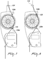
- Figs. 7 and 8 show an alternative embodiment of the invention, in which the elements similar to the previous embodiment are designated by the same reference numerals increased by 100.
- Such embodiment differs from the previous one only in that the rotation travel of the spacer pin 120 is delimited both in the direction of unwinding by first means of arrest 138a, and in the direction of winding by second means of arrest 138b.
- the first means of arrest 138a and the second means of arrest 138b are arranged so as to block the rotation of the spacer pin 120 in positions such that the incoming yarn is not deviated, either during unwinding or during recovery.
- the yarn arriving from the entry yarn guiding bush 124 could also pass outside the spacer pin 120 before being wound on the spool.
- the spacer pin is mounted on a flywheel for an effective balancing of the centrifugal loads, it could alternatively be supported by other rotating supporting means, e.g., a rotating arm optionally ballasted on the opposite side.
- spacer pin could also be pivoted eccentrically, or about a skew axis with respect to the spool, e.g., in order to vary the tensioning curve during recovery.
- the abutments could be substituted by different means of arrest as long as they are capable of blocking the rotation of the pin at a desired point, including electrically-actuated pins, or even mechanical or magnetic brakes or brakes of any other type.
- the arrest positions of the spacer pin can be varied according to requirements.
Landscapes
- Engineering & Computer Science (AREA)
- Textile Engineering (AREA)
- Tension Adjustment In Filamentary Materials (AREA)
- Yarns And Mechanical Finishing Of Yarns Or Ropes (AREA)
- Spinning Methods And Devices For Manufacturing Artificial Fibers (AREA)
Applications Claiming Priority (1)
| Application Number | Priority Date | Filing Date | Title |
|---|---|---|---|
| ITUA2016A004460A ITUA20164460A1 (it) | 2016-06-17 | 2016-06-17 | Alimentatore di filato con rocchetto avvolgi-filo motorizzato |
Publications (2)
| Publication Number | Publication Date |
|---|---|
| EP3257984A1 true EP3257984A1 (de) | 2017-12-20 |
| EP3257984B1 EP3257984B1 (de) | 2020-03-18 |
Family
ID=57209713
Family Applications (1)
| Application Number | Title | Priority Date | Filing Date |
|---|---|---|---|
| EP17176106.7A Active EP3257984B1 (de) | 2016-06-17 | 2017-06-14 | Garnzuführer mit motorisierter garnwickelspule |
Country Status (4)
| Country | Link |
|---|---|
| US (1) | US10358751B2 (de) |
| EP (1) | EP3257984B1 (de) |
| CN (1) | CN107522023B (de) |
| IT (1) | ITUA20164460A1 (de) |
Cited By (2)
| Publication number | Priority date | Publication date | Assignee | Title |
|---|---|---|---|---|
| IT201800005840A1 (it) * | 2018-05-30 | 2019-11-30 | Alimentatore di filato con rocchetto avvolgi-filo motorizzato e sistema di riavvolgimento | |
| EP4202097A1 (de) | 2021-12-21 | 2023-06-28 | L.G.L. Electronics S.p.A. | Verfahren zur verwaltung von betriebsdaten in einer textilvorrichtung mit mehreren fadenliefervorrichtungen |
Families Citing this family (6)
| Publication number | Priority date | Publication date | Assignee | Title |
|---|---|---|---|---|
| IT201800002452A1 (it) * | 2018-02-06 | 2019-08-06 | Btsr Int Spa | Metodo, sistema alimentatore di filo perfezionato e dispositivo per ottimizzare l'alimentazione di filo ad una macchina tessile operante con elevata discontinuita' o con un moto alternato |
| BE1027360B1 (nl) | 2019-06-12 | 2021-01-20 | Vandewiele Nv | Garenvoedingsmodule |
| TWI727894B (zh) * | 2020-09-28 | 2021-05-11 | 全通生醫有限公司 | 創傷敷料 |
| US11885052B2 (en) * | 2020-10-02 | 2024-01-30 | Polyvalor, Limited Partnership | Braiding machines and carriers for braiding machines |
| CN113235176B (zh) * | 2021-05-24 | 2022-11-25 | 中国纺织科学研究院有限公司 | 一种纺丝用牵伸辊及纺丝组件 |
| USD1026049S1 (en) * | 2022-09-30 | 2024-05-07 | Btsr International S.P.A. | Yarn feeder |
Citations (2)
| Publication number | Priority date | Publication date | Assignee | Title |
|---|---|---|---|---|
| US20070210198A1 (en) * | 2004-10-21 | 2007-09-13 | Memminger-Iro Gmbh | Yarn delivering apparatus having a yarn return operating mode |
| EP1501970B1 (de) | 2002-05-03 | 2011-06-01 | Tiziano Barea | Verfahren und vorrichtung zur fadenspannungskonstanten fadenlieferung und rückspulung eines zu einer textilmaschine gelieferten garnes |
Family Cites Families (6)
| Publication number | Priority date | Publication date | Assignee | Title |
|---|---|---|---|---|
| JPS5419396Y2 (de) * | 1973-10-01 | 1979-07-18 | ||
| DE19811241A1 (de) * | 1998-03-14 | 1999-09-30 | Memminger Iro Gmbh | Fadenspannungssensor mit wiederholtem Abgleich |
| DE19811240C2 (de) * | 1998-03-14 | 2000-05-31 | Memminger Iro Gmbh | Fadenliefergerät mit verbessertem Fadenlauf |
| ITMI20020770A1 (it) * | 2002-04-10 | 2003-10-10 | Tiziano Barea | Dispositivo e metodo per alimentare un filo elastomerico ad una macchina tessile al fine di avere un manufatto di qualita' costante in ogni |
| EP2204481B1 (de) * | 2008-12-30 | 2013-07-10 | L.G.L. Electronics S.p.A. | Positive Fadenliefervorrichtung mit Zugkraftbegrenzer |
| ITTO20120435A1 (it) * | 2012-05-17 | 2013-11-18 | Lgl Electronics Spa | Alimentatore di filato a tamburo rotante per macchine tessili. |
-
2016
- 2016-06-17 IT ITUA2016A004460A patent/ITUA20164460A1/it unknown
-
2017
- 2017-06-14 EP EP17176106.7A patent/EP3257984B1/de active Active
- 2017-06-15 US US15/624,133 patent/US10358751B2/en active Active
- 2017-06-16 CN CN201710456861.4A patent/CN107522023B/zh active Active
Patent Citations (2)
| Publication number | Priority date | Publication date | Assignee | Title |
|---|---|---|---|---|
| EP1501970B1 (de) | 2002-05-03 | 2011-06-01 | Tiziano Barea | Verfahren und vorrichtung zur fadenspannungskonstanten fadenlieferung und rückspulung eines zu einer textilmaschine gelieferten garnes |
| US20070210198A1 (en) * | 2004-10-21 | 2007-09-13 | Memminger-Iro Gmbh | Yarn delivering apparatus having a yarn return operating mode |
Cited By (4)
| Publication number | Priority date | Publication date | Assignee | Title |
|---|---|---|---|---|
| IT201800005840A1 (it) * | 2018-05-30 | 2019-11-30 | Alimentatore di filato con rocchetto avvolgi-filo motorizzato e sistema di riavvolgimento | |
| EP3575253A1 (de) | 2018-05-30 | 2019-12-04 | L.G.L. Electronics S.p.A. | Fadenführung mit motorisierter fadenwickelspule und umspulsystem |
| US10947649B2 (en) | 2018-05-30 | 2021-03-16 | L.G.L. Electronics S.P.A. | Yarn feeder with motorized yarn-winding spool and rewinding system |
| EP4202097A1 (de) | 2021-12-21 | 2023-06-28 | L.G.L. Electronics S.p.A. | Verfahren zur verwaltung von betriebsdaten in einer textilvorrichtung mit mehreren fadenliefervorrichtungen |
Also Published As
| Publication number | Publication date |
|---|---|
| CN107522023B (zh) | 2020-11-10 |
| EP3257984B1 (de) | 2020-03-18 |
| ITUA20164460A1 (it) | 2017-12-17 |
| CN107522023A (zh) | 2017-12-29 |
| US20170362752A1 (en) | 2017-12-21 |
| US10358751B2 (en) | 2019-07-23 |
Similar Documents
| Publication | Publication Date | Title |
|---|---|---|
| EP3257984A1 (de) | Garnzuführer mit motorisierter garnwickelspule | |
| US8584981B2 (en) | Positive yarn feeder with tension limiter | |
| ITTO940577A1 (it) | Dispositivo per la regolazione della tensione di un filo. | |
| EP2642004B1 (de) | Garnzuführungs-/-rückgewinnungsverfahren für Textilmaschinen, und Vorrichtung zur Durchführung eines solchen Verfahrens | |
| EP3336864B1 (de) | Vorrichtung für automatische drahtspannungsanpassungen während verschiedener stufen von wickelmaschinen zum wickeln von elektrischen spulen | |
| EP2080724A3 (de) | System zur Steuerung der Zufuhr eines Garns oder Drahts zu einer Maschine und verwandtes Verfahren | |
| EP1717182B1 (de) | Vorrichtung zur Beseitigung von Fadenlockerungen in einer Textilmaschine | |
| CN106087142B (zh) | 倍捻机或并捻机的锭子运行方法和相应的倍捻机或并捻机 | |
| EP3575253A1 (de) | Fadenführung mit motorisierter fadenwickelspule und umspulsystem | |
| EP2829647B1 (de) | Garnzuführvorrichtung mit Schussfaden-Wickeltrommel und feedbackgesteuerter Schussfaden-Bremsvorrichtung | |
| SE413519B (sv) | Anordning for matning av garn fran ett forrad med konstant och instellbar spenning till en vevstol eller stickmaskin | |
| EP2866236A1 (de) | Vorrichtung für automatische Drahtspannungsanpassungen während verschiedener Stufen von Wickelmaschinen zum Wickeln von elektrischen Spulen | |
| EP3763650B1 (de) | Verfahren zum zuführen mehrerer fäden zu einer textilmaschine über jeweils positive fadenzufürvorrichtungen | |
| EP2754742A1 (de) | Garnzufuhranordnung für Textilmaschinen | |
| EP1741817B1 (de) | Faden-Rückzugsvorrichtung für Textilmaschinen | |
| US3999717A (en) | Thread delivery device for textile machines | |
| CN217076496U (zh) | 自动卷纱装置及浆纱设备 | |
| CN213112040U (zh) | 一种金刚线收放线装置 | |
| KR101628075B1 (ko) | 높이 감지기능을 구비하는 소형 무대 승강장치 | |
| CN113307093A (zh) | 自动卷纱装置及浆纱设备 | |
| EP2631339B1 (de) | Garnzuführungsvorrichtungen mit geregelter Spannung für Textilmaschinen, mit Garnrückgewinnungsfunktion | |
| KR102709762B1 (ko) | 장력 자동 조절이 가능한 연선기 | |
| EP2853626B1 (de) | Garnzuführung mit Speichertrommel | |
| EP0735171A1 (de) | Fadenzuführ- und Spannvorrichtung in einer Textilmaschine | |
| KR840000769Y1 (ko) | 직기에 있어서 간접권취용 클로스로울러의 구동장치 |
Legal Events
| Date | Code | Title | Description |
|---|---|---|---|
| PUAI | Public reference made under article 153(3) epc to a published international application that has entered the european phase |
Free format text: ORIGINAL CODE: 0009012 |
|
| STAA | Information on the status of an ep patent application or granted ep patent |
Free format text: STATUS: THE APPLICATION HAS BEEN PUBLISHED |
|
| AK | Designated contracting states |
Kind code of ref document: A1 Designated state(s): AL AT BE BG CH CY CZ DE DK EE ES FI FR GB GR HR HU IE IS IT LI LT LU LV MC MK MT NL NO PL PT RO RS SE SI SK SM TR |
|
| AX | Request for extension of the european patent |
Extension state: BA ME |
|
| STAA | Information on the status of an ep patent application or granted ep patent |
Free format text: STATUS: REQUEST FOR EXAMINATION WAS MADE |
|
| 17P | Request for examination filed |
Effective date: 20180416 |
|
| RBV | Designated contracting states (corrected) |
Designated state(s): AL AT BE BG CH CY CZ DE DK EE ES FI FR GB GR HR HU IE IS IT LI LT LU LV MC MK MT NL NO PL PT RO RS SE SI SK SM TR |
|
| STAA | Information on the status of an ep patent application or granted ep patent |
Free format text: STATUS: EXAMINATION IS IN PROGRESS |
|
| 17Q | First examination report despatched |
Effective date: 20190418 |
|
| GRAP | Despatch of communication of intention to grant a patent |
Free format text: ORIGINAL CODE: EPIDOSNIGR1 |
|
| STAA | Information on the status of an ep patent application or granted ep patent |
Free format text: STATUS: GRANT OF PATENT IS INTENDED |
|
| INTG | Intention to grant announced |
Effective date: 20191028 |
|
| GRAS | Grant fee paid |
Free format text: ORIGINAL CODE: EPIDOSNIGR3 |
|
| GRAA | (expected) grant |
Free format text: ORIGINAL CODE: 0009210 |
|
| STAA | Information on the status of an ep patent application or granted ep patent |
Free format text: STATUS: THE PATENT HAS BEEN GRANTED |
|
| AK | Designated contracting states |
Kind code of ref document: B1 Designated state(s): AL AT BE BG CH CY CZ DE DK EE ES FI FR GB GR HR HU IE IS IT LI LT LU LV MC MK MT NL NO PL PT RO RS SE SI SK SM TR |
|
| REG | Reference to a national code |
Ref country code: GB Ref legal event code: FG4D |
|
| REG | Reference to a national code |
Ref country code: DE Ref legal event code: R096 Ref document number: 602017013135 Country of ref document: DE |
|
| REG | Reference to a national code |
Ref country code: AT Ref legal event code: REF Ref document number: 1246013 Country of ref document: AT Kind code of ref document: T Effective date: 20200415 Ref country code: IE Ref legal event code: FG4D |
|
| PG25 | Lapsed in a contracting state [announced via postgrant information from national office to epo] |
Ref country code: NO Free format text: LAPSE BECAUSE OF FAILURE TO SUBMIT A TRANSLATION OF THE DESCRIPTION OR TO PAY THE FEE WITHIN THE PRESCRIBED TIME-LIMIT Effective date: 20200618 Ref country code: FI Free format text: LAPSE BECAUSE OF FAILURE TO SUBMIT A TRANSLATION OF THE DESCRIPTION OR TO PAY THE FEE WITHIN THE PRESCRIBED TIME-LIMIT Effective date: 20200318 Ref country code: RS Free format text: LAPSE BECAUSE OF FAILURE TO SUBMIT A TRANSLATION OF THE DESCRIPTION OR TO PAY THE FEE WITHIN THE PRESCRIBED TIME-LIMIT Effective date: 20200318 |
|
| REG | Reference to a national code |
Ref country code: NL Ref legal event code: MP Effective date: 20200318 |
|
| PG25 | Lapsed in a contracting state [announced via postgrant information from national office to epo] |
Ref country code: HR Free format text: LAPSE BECAUSE OF FAILURE TO SUBMIT A TRANSLATION OF THE DESCRIPTION OR TO PAY THE FEE WITHIN THE PRESCRIBED TIME-LIMIT Effective date: 20200318 Ref country code: SE Free format text: LAPSE BECAUSE OF FAILURE TO SUBMIT A TRANSLATION OF THE DESCRIPTION OR TO PAY THE FEE WITHIN THE PRESCRIBED TIME-LIMIT Effective date: 20200318 Ref country code: LV Free format text: LAPSE BECAUSE OF FAILURE TO SUBMIT A TRANSLATION OF THE DESCRIPTION OR TO PAY THE FEE WITHIN THE PRESCRIBED TIME-LIMIT Effective date: 20200318 Ref country code: GR Free format text: LAPSE BECAUSE OF FAILURE TO SUBMIT A TRANSLATION OF THE DESCRIPTION OR TO PAY THE FEE WITHIN THE PRESCRIBED TIME-LIMIT Effective date: 20200619 Ref country code: BG Free format text: LAPSE BECAUSE OF FAILURE TO SUBMIT A TRANSLATION OF THE DESCRIPTION OR TO PAY THE FEE WITHIN THE PRESCRIBED TIME-LIMIT Effective date: 20200618 |
|
| REG | Reference to a national code |
Ref country code: LT Ref legal event code: MG4D |
|
| PG25 | Lapsed in a contracting state [announced via postgrant information from national office to epo] |
Ref country code: NL Free format text: LAPSE BECAUSE OF FAILURE TO SUBMIT A TRANSLATION OF THE DESCRIPTION OR TO PAY THE FEE WITHIN THE PRESCRIBED TIME-LIMIT Effective date: 20200318 |
|
| PG25 | Lapsed in a contracting state [announced via postgrant information from national office to epo] |
Ref country code: CZ Free format text: LAPSE BECAUSE OF FAILURE TO SUBMIT A TRANSLATION OF THE DESCRIPTION OR TO PAY THE FEE WITHIN THE PRESCRIBED TIME-LIMIT Effective date: 20200318 Ref country code: IS Free format text: LAPSE BECAUSE OF FAILURE TO SUBMIT A TRANSLATION OF THE DESCRIPTION OR TO PAY THE FEE WITHIN THE PRESCRIBED TIME-LIMIT Effective date: 20200718 Ref country code: SK Free format text: LAPSE BECAUSE OF FAILURE TO SUBMIT A TRANSLATION OF THE DESCRIPTION OR TO PAY THE FEE WITHIN THE PRESCRIBED TIME-LIMIT Effective date: 20200318 Ref country code: PT Free format text: LAPSE BECAUSE OF FAILURE TO SUBMIT A TRANSLATION OF THE DESCRIPTION OR TO PAY THE FEE WITHIN THE PRESCRIBED TIME-LIMIT Effective date: 20200812 Ref country code: EE Free format text: LAPSE BECAUSE OF FAILURE TO SUBMIT A TRANSLATION OF THE DESCRIPTION OR TO PAY THE FEE WITHIN THE PRESCRIBED TIME-LIMIT Effective date: 20200318 Ref country code: LT Free format text: LAPSE BECAUSE OF FAILURE TO SUBMIT A TRANSLATION OF THE DESCRIPTION OR TO PAY THE FEE WITHIN THE PRESCRIBED TIME-LIMIT Effective date: 20200318 Ref country code: SM Free format text: LAPSE BECAUSE OF FAILURE TO SUBMIT A TRANSLATION OF THE DESCRIPTION OR TO PAY THE FEE WITHIN THE PRESCRIBED TIME-LIMIT Effective date: 20200318 Ref country code: RO Free format text: LAPSE BECAUSE OF FAILURE TO SUBMIT A TRANSLATION OF THE DESCRIPTION OR TO PAY THE FEE WITHIN THE PRESCRIBED TIME-LIMIT Effective date: 20200318 |
|
| REG | Reference to a national code |
Ref country code: AT Ref legal event code: MK05 Ref document number: 1246013 Country of ref document: AT Kind code of ref document: T Effective date: 20200318 |
|
| REG | Reference to a national code |
Ref country code: DE Ref legal event code: R097 Ref document number: 602017013135 Country of ref document: DE |
|
| PLBE | No opposition filed within time limit |
Free format text: ORIGINAL CODE: 0009261 |
|
| STAA | Information on the status of an ep patent application or granted ep patent |
Free format text: STATUS: NO OPPOSITION FILED WITHIN TIME LIMIT |
|
| PG25 | Lapsed in a contracting state [announced via postgrant information from national office to epo] |
Ref country code: DK Free format text: LAPSE BECAUSE OF FAILURE TO SUBMIT A TRANSLATION OF THE DESCRIPTION OR TO PAY THE FEE WITHIN THE PRESCRIBED TIME-LIMIT Effective date: 20200318 Ref country code: AT Free format text: LAPSE BECAUSE OF FAILURE TO SUBMIT A TRANSLATION OF THE DESCRIPTION OR TO PAY THE FEE WITHIN THE PRESCRIBED TIME-LIMIT Effective date: 20200318 Ref country code: MC Free format text: LAPSE BECAUSE OF FAILURE TO SUBMIT A TRANSLATION OF THE DESCRIPTION OR TO PAY THE FEE WITHIN THE PRESCRIBED TIME-LIMIT Effective date: 20200318 Ref country code: ES Free format text: LAPSE BECAUSE OF FAILURE TO SUBMIT A TRANSLATION OF THE DESCRIPTION OR TO PAY THE FEE WITHIN THE PRESCRIBED TIME-LIMIT Effective date: 20200318 |
|
| REG | Reference to a national code |
Ref country code: CH Ref legal event code: PL |
|
| 26N | No opposition filed |
Effective date: 20201221 |
|
| PG25 | Lapsed in a contracting state [announced via postgrant information from national office to epo] |
Ref country code: PL Free format text: LAPSE BECAUSE OF FAILURE TO SUBMIT A TRANSLATION OF THE DESCRIPTION OR TO PAY THE FEE WITHIN THE PRESCRIBED TIME-LIMIT Effective date: 20200318 |
|
| PG25 | Lapsed in a contracting state [announced via postgrant information from national office to epo] |
Ref country code: LU Free format text: LAPSE BECAUSE OF NON-PAYMENT OF DUE FEES Effective date: 20200614 |
|
| PG25 | Lapsed in a contracting state [announced via postgrant information from national office to epo] |
Ref country code: LI Free format text: LAPSE BECAUSE OF NON-PAYMENT OF DUE FEES Effective date: 20200630 Ref country code: CH Free format text: LAPSE BECAUSE OF NON-PAYMENT OF DUE FEES Effective date: 20200630 Ref country code: FR Free format text: LAPSE BECAUSE OF NON-PAYMENT OF DUE FEES Effective date: 20200630 Ref country code: IE Free format text: LAPSE BECAUSE OF NON-PAYMENT OF DUE FEES Effective date: 20200614 |
|
| PG25 | Lapsed in a contracting state [announced via postgrant information from national office to epo] |
Ref country code: SI Free format text: LAPSE BECAUSE OF FAILURE TO SUBMIT A TRANSLATION OF THE DESCRIPTION OR TO PAY THE FEE WITHIN THE PRESCRIBED TIME-LIMIT Effective date: 20200318 |
|
| PG25 | Lapsed in a contracting state [announced via postgrant information from national office to epo] |
Ref country code: MT Free format text: LAPSE BECAUSE OF FAILURE TO SUBMIT A TRANSLATION OF THE DESCRIPTION OR TO PAY THE FEE WITHIN THE PRESCRIBED TIME-LIMIT Effective date: 20200318 Ref country code: CY Free format text: LAPSE BECAUSE OF FAILURE TO SUBMIT A TRANSLATION OF THE DESCRIPTION OR TO PAY THE FEE WITHIN THE PRESCRIBED TIME-LIMIT Effective date: 20200318 |
|
| PG25 | Lapsed in a contracting state [announced via postgrant information from national office to epo] |
Ref country code: MK Free format text: LAPSE BECAUSE OF FAILURE TO SUBMIT A TRANSLATION OF THE DESCRIPTION OR TO PAY THE FEE WITHIN THE PRESCRIBED TIME-LIMIT Effective date: 20200318 Ref country code: AL Free format text: LAPSE BECAUSE OF FAILURE TO SUBMIT A TRANSLATION OF THE DESCRIPTION OR TO PAY THE FEE WITHIN THE PRESCRIBED TIME-LIMIT Effective date: 20200318 |
|
| P01 | Opt-out of the competence of the unified patent court (upc) registered |
Effective date: 20230527 |
|
| PGFP | Annual fee paid to national office [announced via postgrant information from national office to epo] |
Ref country code: DE Payment date: 20250613 Year of fee payment: 9 |
|
| PGFP | Annual fee paid to national office [announced via postgrant information from national office to epo] |
Ref country code: GB Payment date: 20250612 Year of fee payment: 9 |
|
| PGFP | Annual fee paid to national office [announced via postgrant information from national office to epo] |
Ref country code: BE Payment date: 20250613 Year of fee payment: 9 Ref country code: IT Payment date: 20250520 Year of fee payment: 9 |
|
| PGFP | Annual fee paid to national office [announced via postgrant information from national office to epo] |
Ref country code: TR Payment date: 20250611 Year of fee payment: 9 |