EP3258019B1 - Sanitärarmatur und verfahren zum bereitstellen einer wässrigen reinigungsflüssigkeit oder eines reinigungsschaums mittels saugheber - Google Patents
Sanitärarmatur und verfahren zum bereitstellen einer wässrigen reinigungsflüssigkeit oder eines reinigungsschaums mittels saugheber Download PDFInfo
- Publication number
- EP3258019B1 EP3258019B1 EP17000979.9A EP17000979A EP3258019B1 EP 3258019 B1 EP3258019 B1 EP 3258019B1 EP 17000979 A EP17000979 A EP 17000979A EP 3258019 B1 EP3258019 B1 EP 3258019B1
- Authority
- EP
- European Patent Office
- Prior art keywords
- fluid
- sanitary fitting
- container
- conducting element
- siphon
- Prior art date
- Legal status (The legal status is an assumption and is not a legal conclusion. Google has not performed a legal analysis and makes no representation as to the accuracy of the status listed.)
- Active
Links
Images
Classifications
-
- E—FIXED CONSTRUCTIONS
- E03—WATER SUPPLY; SEWERAGE
- E03C—DOMESTIC PLUMBING INSTALLATIONS FOR FRESH WATER OR WASTE WATER; SINKS
- E03C1/00—Domestic plumbing installations for fresh water or waste water; Sinks
- E03C1/02—Plumbing installations for fresh water
- E03C1/04—Water-basin installations specially adapted to wash-basins or baths
- E03C1/046—Adding soap, disinfectant, or the like in the supply line or at the water outlet
Definitions
- the US 8 702 018 B1 discloses a device in which soap or shampoo is sucked out of a container by means of a Venturi nozzle.
- a disadvantage of this device is that a continuously high flow rate of the water is required for a continuous mixing of the water with the soap or the shampoo to generate a sufficiently high negative pressure. The use of the device therefore leads to high water consumption.
- Corresponding devices are also from the US 2005-0150909 A1 , US 4,121,773 , US 5,333,789 , DE 10 2010 013993 A1 and US 4 901765 known.
- Another object of the invention is to provide a sanitary fitting that is as low-wear or low-maintenance as possible, or both, from which a mixture of cleaning liquid and water can be removed. Furthermore, it is an object of the present invention to provide the above-mentioned sanitary fitting, the foam being able to be removed from the mixture. Furthermore, it is an object of the present invention to provide the aforementioned sanitary fitting, the mixture or drinking water optionally being able to be removed from it. It is a further object of the invention to provide a sanitary fitting from which a mixture of cleaning liquid and water can be removed, the sanitary fitting working as energy-saving as possible.
- the independent claims contribute to at least partially fulfilling at least one of the above tasks.
- the dependent claims provide preferred embodiments that help at least partially accomplish at least one of the tasks.
- the sanitary fitting is designed according to embodiment 1, the container containing a cleaning liquid or a disinfectant or both.
- a preferred cleaning liquid contains soap.
- a preferred soap-containing cleaning liquid is a hand wash paste or a liquid soap or both.
- Another preferred cleaning liquid is one selected from the group consisting of a washing lotion, a cleaning gel, a cleaning milk and a detergent, or a combination of at least two of them.
- the sanitary fitting is designed according to one of the preceding embodiments, the sanitary fitting further comprising an injector nozzle between the suction lifter and the fluid-conducting element.
- a preferred injector nozzle is a Venturi nozzle.
- the sanitary fitting is designed according to one of the preceding embodiments, the suction lifter or the fluid-conducting element or both being connected to a snifting valve.
- the sniffer valve is preferably designed and arranged for introducing air into the siphon or the fluid-conducting element or both. Furthermore, the sniffer valve is preferably designed and arranged to foam a cleaning liquid in the fluid-conducting element.
- the sanitary fitting is designed according to one of the preceding embodiments, the device further comprising an inflow fitting, the inflow fitting being connected in a fluid-conducting manner to the fluid supply line.
- An embodiment 1 of bathroom equipment including the sanitary fitting according to one of its embodiments 1 to 5, makes a contribution to fulfilling at least one of the tasks according to the invention.
- An embodiment 1 of a toilet room equipment including the sanitary fitting according to one of its embodiments 1 to 5, makes a contribution to fulfilling at least one of the tasks according to the invention.
- An embodiment 1 of a sink including a sink and the sanitary fitting according to one of its embodiments 1 to 5, makes a contribution to fulfilling at least one of the tasks according to the invention.
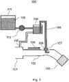
- FIG. 1 shows a schematic representation of a sanitary fitting 100 according to the invention.
- the sanitary fitting 100 contains a fluid supply line 101 which can be connected to a drinking water line; a fluid conducting element 102; a fluid outlet 103 including a jet regulator; a container 104; and a suction lifter 105.
- the fluid outlet 103 is connected to the fluid supply line 101 via the fluid-conducting element 102.
- the container 104 is fluidly connected to the fluid-conducting element 102 via the suction lifter 105.
- the container 104 and the suction lifter 105 contain a cleaning liquid 106, here liquid soap.
- the sanitary fitting 100 contains an injector nozzle 107, here a Venturi nozzle, between the suction lifter 105 and the fluid-conducting element 102.
- An arrow in Figure 1 denotes a flow direction 108.
- the container 104 is fluidly connected to the fluid-conducting element 102 at a first connection point 109 via the suction lifter 105, and the fluid feed line 101 in the flow direction 108 before the first connection point 109 is fluidly connected to the container 104 at a further connection point 110 .
- the latter connection is designed to rinse the container 104 and the suction lifter 105 with water from the fluid supply line 101 for cleaning purposes.
- the sanitary fitting 100 further contains a further container 111 which is filled with the liquid soap.
- the container 104 is a dosing container
- the further container 111 is a storage container.
- the volume of the storage container is 10 liters.
- a volume of the dosing container is 3 ml.
- the sanitary fitting 100 also contains a conveying device 112, here a pump between the container 104 and the further container 111.
- the pump is designed to convey the liquid soap from the further container 111 into the container 104.
- the sanitary fitting 100 can be removed via the fluid outlet 103 a mixture of water and liquid soap until the dosing container is emptied. Clear water then flows from the fluid outlet for rinsing. 30 seconds after emptying the dosing container, it is automatically filled with liquid soap from the storage container by means of a sensor and the pump.
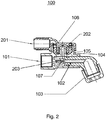
- FIG 2 shows a technical drawing of a further sanitary fitting 100 according to the invention.
- the sanitary fitting 100 contains a fluid supply line 101 which can be connected to a drinking water line; a fluid conducting element 102; a fluid outlet 103 including a jet regulator; a container 104 and a suction lifter 105.
- the fluid outlet 103 is connected to the fluid supply line 101 via the fluid-conducting element 102.
- the container 104 contains a liquid soap 106.
- a supply line 201 from a further container 111 containing the liquid soap is indicated, the further container 111 belonging to the sanitary fitting 100, but not shown here.
- the feed line 201 is fluidly connected to the fluid-conducting element 102 via the suction lifter 105 and an injector nozzle 107, here a Venturi nozzle.
- the suction lifter 105 is also connected to a snifting valve 202.
- the sanitary fitting 100 also has a cleaning needle 203 in the fluid-conducting element 102.
- the cleaning needle 203 is arranged to be movable in a flow direction 108 and counter to this flow direction and prevents the fluid-conducting element from becoming blocked.
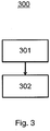
- Figure 3 shows a flow diagram of a method 300 according to the invention.
- the method 300 includes a method step a) 301: providing a water pipe and the sanitary fitting 100 after Figure 2 ; and a method step b) 302: water-conducting connection of the water line to the sanitary fitting 100.
Landscapes
- Health & Medical Sciences (AREA)
- Life Sciences & Earth Sciences (AREA)
- Engineering & Computer Science (AREA)
- Hydrology & Water Resources (AREA)
- Public Health (AREA)
- Water Supply & Treatment (AREA)
- Cleaning By Liquid Or Steam (AREA)
- Sanitary Device For Flush Toilet (AREA)
Description
- Die vorliegende Erfindung betrifft eine Sanitärarmatur, beinhaltend
- a) eine Fluidzuleitung,
- b) ein fluidleitendes Element,
- c) einen Fluidauslass,
- d) einen Behälter, und
- e) einen Saugheber,
- Im technischen Gebiet der Sanitärarmaturen besteht ein Bedürfnis nach Armaturen, die Seife mit Wasser zu einer wässrigen Seifenlösung zusammenführen und so aus dem Armaturenauslauf wahlweise die wässrige Seifenlösung oder reines Wasser abgeben können. Im Stand der Technik werden für das Zusammenführen von Seife und Wasser aufwendige mechanische Konstruktionen mit mehreren beweglichen Teilen, beispielsweise mit Zahnradantrieb und mehreren Steuerelementen oder mit Steuerkolben und Rückflussverhinderern, eingesetzt.
- Die
US 8 702 018 B1 offenbart eine Vorrichtung, bei der Seife oder Shampoo mittels einer Venturidüse aus einem Behälter gesaugt wird. Nachteilig an dieser Vorrichtung ist, dass für ein kontinuierliches Mischen des Wassers mit der Seife oder dem Shampoo eine kontinuierlich hohe Durchflussgeschwindigkeit des Wassers erforderlich ist, um einen ausreichend hohen Unterdruck zu erzeugen. Die Verwendung der Vorrichtung führt daher zu einem hohen Wasserverbrauch. Entsprechende Vorrichtungen sind auch aus derUS 2005-0150909 A1 ,US 4 121 773 ,US 5 333 789 ,DE 10 2010 013993 A1 undUS 4 901765 bekannt. - Allgemein ist es eine Aufgabe der vorliegenden Erfindung, einen Nachteil, der sich aus dem Stand der Technik ergibt, zumindest teilweise zu überwinden. Eine weitere Aufgabe der Erfindung ist es, eine möglichst verschleißarme oder wartungsarme oder beides Sanitärarmatur, aus welcher ein Gemisch aus Reinigungsflüssigkeit und Wasser entnehmbar ist, bereitzustellen. Ferner ist es eine Aufgabe der vorliegenden Erfindung die vorgenannte Sanitärarmatur bereitzustellen, wobei dieser das Gemisch aufgeschäumt entnehmbar ist. Ferner ist es eine Aufgabe der vorliegenden Erfindung die vorgenannte Sanitärarmatur bereitzustellen, wobei dieser wahlweise das Gemisch oder Trinkwasser entnehmbar ist. Ferner ist es eine weitere Aufgabe der Erfindung, eine Sanitärarmatur, aus welcher ein Gemisch aus Reinigungsflüssigkeit und Wasser entnehmbar ist, bereitzustellen, wobei die Sanitärarmatur möglichst energiesparend arbeitet.
- Ein Beitrag zur mindestens teilweisen Erfüllung mindestens einer der obigen Aufgaben wird durch die unabhängigen Ansprüche geleistet. Die abhängigen Ansprüche stellen bevorzugte Ausführungsformen bereit, die zur mindestens teilweisen Erfüllung mindestens einer der Aufgaben beitragen.
- Einen Beitrag zur Erfüllung mindestens einer der erfindungsgemäßen Aufgaben leistet eine Ausführungsform 1 einer Sanitärarmatur, beinhaltend
- a) eine Fluidzuleitung,
- b) ein fluidleitendes Element,
- c) einen Fluidauslass, wobei der Fluidauslass über das fluidleitende Element fluidleitend mit der Fluidzuleitung verbunden ist, und
- d) einen Behälter, wobei die Sanitärarmatur zudem
- e) einen Saugheber umfasst,
- In einer erfindungsgemäßen Ausführungsform 2 ist die Sanitärarmatur nach der Ausführungsform 1 ausgestaltet, wobei der Behälter eine Reinigungsflüssigkeit oder ein Desinfektionsmittel oder beides beinhaltet. Eine bevorzugte Reinigungsflüssigkeit beinhaltet Seife. Eine bevorzugte seifenhaltige Reinigungsflüssigkeit ist eine Handwaschpaste oder eine Flüssigseife oder beides.
- Eine weitere bevorzugte Reinigungsflüssigkeit ist eine ausgewählt aus der Gruppe bestehend aus einer Waschlotion, einem Reinigungsgel, einer Reinigungsmilch und einem Spülmittel oder eine Kombination aus mindestens zwei davon.
- In einer erfindungsgemäßen Ausführungsform 3 ist die Sanitärarmatur nach einer der vorhergehenden Ausführungsformen ausgestaltet, wobei die Sanitärarmatur zwischen dem Saugheber und dem fluidleitenden Element weiter eine Injektordüse beinhaltet. Eine bevorzugte Injektordüse ist ein Venturidüse.
- In einer erfindungsgemäßen Ausführungsform 4 ist die Sanitärarmatur nach einer der vorhergehenden Ausführungsformen ausgestaltet, wobei der Saugheber oder das fluidleitende Element oder beide mit einem Schnüffelventil verbunden ist. Das Schnüffelventil ist bevorzugt ausgebildet und angeordnet zu einem Einbringen von Luft in den Saugheber oder das fluidleitende Element oder beide. Ferner bevorzugt ist das Schnüffelventil ausgebildet und angeordnet zu einem Aufschäumen einer Reinigungsflüssigkeit in dem fluidleitenden Element.
- In einer erfindungsgemäßen Ausführungsform 5 ist die Sanitärarmatur nach einer der vorhergehenden Ausführungsformen ausgestaltet, wobei die Vorrichtung weiter eine Zuflussarmatur beinhaltet, wobei die Zuflussarmatur fluidleitend mit der Fluidzuleitung verbunden ist.
- Einen Beitrag zur Erfüllung mindestens einer der erfindungsgemäßen Aufgaben leistet eine Ausführungsform 1 eines Verfahrens, beinhaltend als Verfahrensschritte
- a) Bereitstellen
- i) einer Wasserleitung, und
- ii) der Sanitärarmatur nach einem der vorhergehenden Ansprüche; und
- b) wasserleitendes Verbinden der Wasserleitung mit der Sanitärarmatur.
- Einen Beitrag zur Erfüllung mindestens einer der erfindungsgemäßen Aufgaben leistet eine Ausführungsform 1 einer Badezimmerausstattung, beinhaltend die Sanitärarmatur nach einer ihrer Ausführungsformen 1 bis 5.
- Einen Beitrag zur Erfüllung mindestens einer der erfindungsgemäßen Aufgaben leistet eine Ausführungsform 1 einer Toilettenraumausstattung, beinhaltend die Sanitärarmatur nach einer ihrer Ausführungsformen 1 bis 5.
- Einen Beitrag zur Erfüllung mindestens einer der erfindungsgemäßen Aufgaben leistet eine Ausführungsform 1 einer Spüle, beinhaltend ein Spülbecken und die Sanitärarmatur nach einer ihrer Ausführungsformen 1 bis 5.
- Die Erfindung wird im Folgenden durch Beispiele und Zeichnungen genauer dargestellt, wobei die Beispiele und Zeichnungen keine Einschränkung der Erfindung bedeuten. Es zeigen jeweils sofern nicht anders in der Beschreibung oder der jeweiligen Figur angegeben schematisch und nicht maßstabsgetreu:
-
Figur 1 eine schematische Darstellung einer erfindungsgemäßen Sanitärarmatur; -
Figur 2 eine technische Zeichnung einer weiteren erfindungsgemäßen Sanitärarmatur; und -
Figur 3 ein Ablaufdiagramm eines erfindungsgemäßen Verfahrens. -
Figur 1 zeigt eine schematische Darstellung einer erfindungsgemäßen Sanitärarmatur 100. Die Sanitärarmatur 100 beinhaltet eine Fluidzuleitung 101, welche an eine Trinkwasserleitung angeschlossen werden kann; ein fluidleitendes Element 102; einen Fluidauslass 103, beinhaltend einen Strahlregler; einen Behälter 104; und einen Saugheber 105. Hierbei ist der Fluidauslass 103 über das fluidleitende Element 102 mit der Fluidzuleitung 101 verbunden. Der Behälter 104 ist über den Saugheber 105 fluidleitend mit dem fluidleitenden Element 102 verbunden. Ferner beinhalten der Behälter 104 und der Saugheber 105 eine Reinigungsflüssigkeit 106, hier Flüssigseife. Weiter beinhaltet die Sanitärarmatur 100 zwischen dem Saugheber 105 und dem fluidleitenden Element 102 eine Injektordüse 107, hier eine Venturidüse. Ein Pfeil inFigur 1 bezeichnet eine Fließrichtung 108. Ferner ist der Behälter 104 über den Saugheber 105 an einer ersten Verbindungsstelle 109 fluidleitend mit dem fluidleitenden Element 102 verbunden und die Fluidzuleitung 101 in der Fließrichtung 108 vor der ersten Verbindungsstelle 109 mit dem Behälter 104 an einer weiteren Verbindungsstelle 110 fluidleitend verbunden. Letztere Verbindung ist ausgebildet zu einem Spülen des Behälters 104 und des Saughebers 105 mit Wasser aus der Fluidzuleitung 101 zu Reinigungszwecken. In der Fließrichtung 108 vor dem Behälter 104 beinhaltet die Sanitärarmatur 100 weiter einen weiteren Behälter 111, welcher mit der Flüssigseife gefüllt ist. Der Behälter 104 ist ein Dosierbehälter, der weitere Behälter 111 ist ein Vorratsbehälter. Ein Fassungsvolumen des Vorratsbehälters beträgt 10 Liter. Ein Fassungsvolumen des Dosierbehälters beträgt 3 ml. Ferner beinhaltet die Sanitärarmatur 100 weiter eine Fördereinrichtung 112, hier eine Pumpe zwischen dem Behälter 104 und dem weiteren Behälter 111. Die Pumpe ist ausgebildet zu einem Fördern der Flüssigseife aus dem weiteren Behälter 111 in den Behälter 104. Die Sanitärarmatur 100 ist über den Fluidauslass 103 eine Mischung aus Wasser und Flüssigseife entnehmbar bis der Dosierbehälter geleert ist. Daraufhin fließt klares Wasser zum Abspülen aus dem Fluidauslass. 30 Sekunden nach dem Entleeren des Dosierbehälters wird dieser mittels eines Sensors und der Pumpe automatisch mit Flüssigseife aus dem Vorratsbehälter aufgefüllt. -
Figur 2 zeigt eine technische Zeichnung einer weiteren erfindungsgemäßen Sanitärarmatur 100. Die Sanitärarmatur 100 beinhaltet eine Fluidzuleitung 101, welche an eine Trinkwasserleitung angeschlossen werden kann; ein fluidleitendes Element 102; einen Fluidauslass 103, beinhaltend einen Strahlregler; einen Behälter 104 und einen Saugheber 105. Hierbei ist der Fluidauslass 103 über das fluidleitende Element 102 mit der Fluidzuleitung 101 verbunden. Der Behälter 104 beinhaltet eine Flüssigseife 106. Ferner ist inFigur 2 eine Zuleitung 201 von einem weiteren Behälter 111, beinhaltend die Flüssigseife, angedeutet, wobei der weitere Behälter 111 zur Sanitärarmatur 100 gehört, hier jedoch nicht dargestellt ist. Die Zuleitung 201 ist über den Saugheber 105 und eine Injektordüse 107, hier eine Venturidüse, fluidleitend mit dem fluidleitenden Element 102 verbunden. Weiter ist der Saugheber 105 mit einem Schnüffelventil 202 verbunden. In einem Bereich der Injektordüse 107 weist die Sanitärarmatur 100 in dem fluidleitenden Element 102 ferner eine Reinigungsnadel 203 auf. Die Reinigungsnadel 203 ist in einer Fließrichtung 108 sowie gegen diese Fließrichtung beweglich angeordnet und verhindert ein Verstopfen des fluidleitenden Elements. -
Figur 3 zeigt ein Ablaufdiagramm eines erfindungsgemäßen Verfahrens 300. Das Verfahren 300 beinhaltet einen Verfahrensschritt a) 301:Bereitstellen einer Wasserleitung und der Sanitärarmatur 100 nachFigur 2 ; und einen Verfahrensschritt b) 302: wasserleitendes Verbinden der Wasserleitung mit der Sanitärarmatur 100. -
- 100
- erfindungsgemäßeSanitärarmatur
- 101
- Fluidzuleitung
- 102
- fluidleitendes Element
- 103
- Fluidauslass
- 104
- Behälter
- 105
- Saugheber
- 106
- Reinigungsflüssigkeit
- 107
- Injektordüse
- 108
- Fließrichtung
- 109
- erste Verbindungsstelle
- 110
- weitere Verbindungsstelle
- 111
- weiterer Behälter
- 112
- Fördereinrichtung
- 201
- Zuleitung von dem weiteren Behälter
- 202
- Schnüffelventil
- 203
- Reinigungsnadel
- 300
- erfindungsgemäßes Verfahren
- 301
- Verfahrensschritt a)
- 302
- Verfahrensschritt b)
Claims (9)
- Sanitärarmatur(100), beinhaltenda) eine Fluidzuleitung (101),b) ein fluidleitendes Element (102),c) einen Fluidauslass (103), wobei der Fluidauslass (103) über das fluidleitende Element (102) fluidleitend mit der Fluidzuleitung (101) verbunden ist, undd) einen Behälter (104),
dadurch gekennzeichnet, dass die Sanitärarmatur (100)e) einen Saugheber (105) umfasst,wobei der Behälter (104) über den Saugheber (105) fluidleitend mit dem fluidleitenden Element (102) verbunden ist. - Die Sanitärarmatur (100) nach Anspruch 1, wobei der Behälter (104) eine Reinigungsflüssigkeit (106) oder ein Desinfektionsmittel oder beides beinhaltet.
- Die Sanitärarmatur (100) nach Anspruch 1 oder 2, wobei die Sanitärarmatur (100) zwischen dem Saugheber (105) und dem fluidleitenden Element (102) weiter eine Injektordüse (107) beinhaltet.
- Die Sanitärarmatur (100) nach einem der vorhergehenden Ansprüche, wobei der Saugheber (105) oder das fluidleitende Element (102) oder beide mit einem Schnüffelventil (202) verbunden ist.
- Die Sanitärarmatur (100) nach einem der vorhergehenden Ansprüche, wobei die Sanitärarmatur (100) weiter eine Zuflussarmatur beinhaltet,
wobei die Zuflussarmatur fluidleitend mit der Fluidzuleitung (101) verbunden ist. - Ein Verfahren (300), beinhaltend als Verfahrensschritte (301, 302)a) Bereitstelleni) einer Wasserleitung, undii) der Sanitärarmatur (100) nach einem der vorhergehenden Ansprüche; undb) wasserleitendes Verbinden der Wasserleitung mit der Sanitärarmatur (100).
- Eine Badezimmerausstattung, beinhaltend die Sanitärarmatur (100) nach einem der Ansprüche 1 bis 5.
- Eine Toilettenraumausstattung, beinhaltend die Sanitärarmatur (100) nach einem der Ansprüche 1 bis 5.
- Eine Spüle, beinhaltend ein Spülbecken und die Sanitärarmatur (100) nach einem der Ansprüche 1 bis 5.
Applications Claiming Priority (1)
| Application Number | Priority Date | Filing Date | Title |
|---|---|---|---|
| DE102016007358.6A DE102016007358A1 (de) | 2016-06-17 | 2016-06-17 | Vorrichtung zum Bereitstellen einer wässrigen Reinigungsflüssigkeit oder eines Reinigungsschaums mittels Saugheber |
Publications (2)
| Publication Number | Publication Date |
|---|---|
| EP3258019A1 EP3258019A1 (de) | 2017-12-20 |
| EP3258019B1 true EP3258019B1 (de) | 2020-08-05 |
Family
ID=59034423
Family Applications (1)
| Application Number | Title | Priority Date | Filing Date |
|---|---|---|---|
| EP17000979.9A Active EP3258019B1 (de) | 2016-06-17 | 2017-06-09 | Sanitärarmatur und verfahren zum bereitstellen einer wässrigen reinigungsflüssigkeit oder eines reinigungsschaums mittels saugheber |
Country Status (2)
| Country | Link |
|---|---|
| EP (1) | EP3258019B1 (de) |
| DE (1) | DE102016007358A1 (de) |
Families Citing this family (1)
| Publication number | Priority date | Publication date | Assignee | Title |
|---|---|---|---|---|
| US20220010535A1 (en) * | 2020-07-10 | 2022-01-13 | Benjamin Martin Haneckow | Siphon Drive Shower |
Citations (3)
| Publication number | Priority date | Publication date | Assignee | Title |
|---|---|---|---|---|
| US618349A (en) * | 1899-01-24 | heany | ||
| DE912920C (de) * | 1951-02-22 | 1954-06-03 | Saalfeld & Dorfmueller Inhaber | Vorrichtung zum Desinfizieren von Abwaessern in Klosetts oder sonstigen Spuelanlagen |
| EP2696003A1 (de) * | 2012-08-08 | 2014-02-12 | Oliveira & Irmao S.A. | Spülkastenbetriebsflüssigkeitspendervorrichtung |
Family Cites Families (6)
| Publication number | Priority date | Publication date | Assignee | Title |
|---|---|---|---|---|
| US4121773A (en) * | 1977-03-28 | 1978-10-24 | Headen James J | Shower head dispenser |
| US4901765A (en) * | 1988-10-31 | 1990-02-20 | Poe Frank C | Coupling for mixing lotions or other liquids with shower water |
| US5333789A (en) * | 1992-08-21 | 1994-08-02 | David Garneys | Soap dispenser insert for a shower head |
| US7028922B2 (en) * | 2004-01-13 | 2006-04-18 | Leonard Brian T | Soap dispenser system and valve arrangement therefor |
| DE102010013993A1 (de) * | 2010-04-07 | 2011-10-13 | Robert Bosch Gmbh | Vorrichtung und Verfahren zum Zuführen mindestens eines zweiten Fluids zu einem ersten strömenden Fluid |
| US8702018B1 (en) * | 2011-09-23 | 2014-04-22 | Santiago Rivera | Universal suds-mix fluidic-circuit bubblizer-chamber |
-
2016
- 2016-06-17 DE DE102016007358.6A patent/DE102016007358A1/de not_active Withdrawn
-
2017
- 2017-06-09 EP EP17000979.9A patent/EP3258019B1/de active Active
Patent Citations (3)
| Publication number | Priority date | Publication date | Assignee | Title |
|---|---|---|---|---|
| US618349A (en) * | 1899-01-24 | heany | ||
| DE912920C (de) * | 1951-02-22 | 1954-06-03 | Saalfeld & Dorfmueller Inhaber | Vorrichtung zum Desinfizieren von Abwaessern in Klosetts oder sonstigen Spuelanlagen |
| EP2696003A1 (de) * | 2012-08-08 | 2014-02-12 | Oliveira & Irmao S.A. | Spülkastenbetriebsflüssigkeitspendervorrichtung |
Also Published As
| Publication number | Publication date |
|---|---|
| EP3258019A1 (de) | 2017-12-20 |
| DE102016007358A1 (de) | 2017-12-21 |
Similar Documents
| Publication | Publication Date | Title |
|---|---|---|
| DE8709117U1 (de) | Mischvorrichtung zum Ausgeben einer Lösung eines Konzentrats in einer Trägerflüssigkeit | |
| DE102018113644A1 (de) | Dosiereinrichtung | |
| DE102010010516A1 (de) | Kaffeemaschine und Verfahren zur Reinigung derselben | |
| DE102015116919A1 (de) | Waschmaschine mit einer Vorrichtung für die Zuführung von Flüssigmitteln und Dosiervorrichtung für Flüssigmittel | |
| DE2158469A1 (en) | Dual additive feeder for dishwashing | |
| EP2885169B1 (de) | Dosiervorrichtung und verfahren zur dosierung von zusatzmitteln in behandlungsflüssigkeiten einer fahrzeugbehandlungsanlage | |
| DE102007023085A1 (de) | Vorrichtung zur Erzeugung von fluiden Reaktionsprodukten | |
| EP3258019B1 (de) | Sanitärarmatur und verfahren zum bereitstellen einer wässrigen reinigungsflüssigkeit oder eines reinigungsschaums mittels saugheber | |
| EP2992793B1 (de) | Verfahren zur reinigung eines milch führenden strömungsleitungssystems eines getränkeautomaten und getränkeautomat zur durchführung des verfahrens | |
| DE102015108438A1 (de) | Vorrichtung zur Reinigung von Automaten für die Herstellung von Heißgetränken, damit ausgerüsteter Automat sowie Verfahren zu dessen Reinigung | |
| DE102018118389A1 (de) | Spülsystem mit integrierter Dosiervorrichtung für Zusatzstoffe | |
| WO2008031622A1 (de) | Reinigungs- und spülvorrichtung für getränke-schankanlagen | |
| DE102009017126B4 (de) | Verfahren zur Wasseraufbereitung sowie Einrichtung hierfür | |
| DE4313292A1 (de) | Verfahren zum Zudosieren einer Chemikalie zu dem Wasserstrom eines Hochdruckreinigungsgerätes | |
| DE102017004912B4 (de) | Vorrichtung zur Desinfektion und/oder Entkalkung insbesondere von Duschköpfen | |
| EP3501351B1 (de) | Getränkeautomat | |
| DE102016115229A1 (de) | Getränkeautomat und Verfahren zur Pflege eines Getränkeautomaten | |
| DE102010040295B4 (de) | Wasserführendes Hausgerät mit zumindest einem Behandlungsmittelbehälter | |
| EP1517213A2 (de) | Dosiergerät zur Herstellung einer Desinfektionsmittelbrauchslösung aus Konzentraten | |
| DE1774820U (de) | Dosiergeraet zum zumischen fluessiger spuel- oder waschmittel in das zuflusswasser von spuel- oder waschanlagen. | |
| DE1143980B (de) | Vorrichtung zum Fuellen und Entleeren von Geschirrspuelmaschinen, Waeschewaschmaschinen u. dgl. | |
| DE960316C (de) | Vorrichtung zum dosierten Zusatz von Fluessigkeiten zu stroemenden anderen Fluessigkeiten | |
| DE818713C (de) | Zweiwegeventil fuer Fluessigkeiten | |
| DE2012358C (de) | Vorrichtung zur Herstellung verdünn ter wäßriger Chemikahenlosungen | |
| DE2012358B2 (de) | Vorrichtung zur herstellung verduennter waessriger chemicalien loesungen |
Legal Events
| Date | Code | Title | Description |
|---|---|---|---|
| PUAI | Public reference made under article 153(3) epc to a published international application that has entered the european phase |
Free format text: ORIGINAL CODE: 0009012 |
|
| STAA | Information on the status of an ep patent application or granted ep patent |
Free format text: STATUS: THE APPLICATION HAS BEEN PUBLISHED |
|
| AK | Designated contracting states |
Kind code of ref document: A1 Designated state(s): AL AT BE BG CH CY CZ DE DK EE ES FI FR GB GR HR HU IE IS IT LI LT LU LV MC MK MT NL NO PL PT RO RS SE SI SK SM TR |
|
| AX | Request for extension of the european patent |
Extension state: BA ME |
|
| STAA | Information on the status of an ep patent application or granted ep patent |
Free format text: STATUS: REQUEST FOR EXAMINATION WAS MADE |
|
| 17P | Request for examination filed |
Effective date: 20180620 |
|
| RBV | Designated contracting states (corrected) |
Designated state(s): AL AT BE BG CH CY CZ DE DK EE ES FI FR GB GR HR HU IE IS IT LI LT LU LV MC MK MT NL NO PL PT RO RS SE SI SK SM TR |
|
| STAA | Information on the status of an ep patent application or granted ep patent |
Free format text: STATUS: EXAMINATION IS IN PROGRESS |
|
| 17Q | First examination report despatched |
Effective date: 20191113 |
|
| GRAP | Despatch of communication of intention to grant a patent |
Free format text: ORIGINAL CODE: EPIDOSNIGR1 |
|
| STAA | Information on the status of an ep patent application or granted ep patent |
Free format text: STATUS: GRANT OF PATENT IS INTENDED |
|
| INTG | Intention to grant announced |
Effective date: 20200429 |
|
| GRAS | Grant fee paid |
Free format text: ORIGINAL CODE: EPIDOSNIGR3 |
|
| GRAA | (expected) grant |
Free format text: ORIGINAL CODE: 0009210 |
|
| STAA | Information on the status of an ep patent application or granted ep patent |
Free format text: STATUS: THE PATENT HAS BEEN GRANTED |
|
| AK | Designated contracting states |
Kind code of ref document: B1 Designated state(s): AL AT BE BG CH CY CZ DE DK EE ES FI FR GB GR HR HU IE IS IT LI LT LU LV MC MK MT NL NO PL PT RO RS SE SI SK SM TR |
|
| REG | Reference to a national code |
Ref country code: GB Ref legal event code: FG4D Free format text: NOT ENGLISH |
|
| REG | Reference to a national code |
Ref country code: CH Ref legal event code: EP |
|
| REG | Reference to a national code |
Ref country code: AT Ref legal event code: REF Ref document number: 1298881 Country of ref document: AT Kind code of ref document: T Effective date: 20200815 |
|
| REG | Reference to a national code |
Ref country code: DE Ref legal event code: R096 Ref document number: 502017006494 Country of ref document: DE |
|
| REG | Reference to a national code |
Ref country code: IE Ref legal event code: FG4D Free format text: LANGUAGE OF EP DOCUMENT: GERMAN |
|
| REG | Reference to a national code |
Ref country code: LT Ref legal event code: MG4D |
|
| REG | Reference to a national code |
Ref country code: NL Ref legal event code: MP Effective date: 20200805 |
|
| PG25 | Lapsed in a contracting state [announced via postgrant information from national office to epo] |
Ref country code: PT Free format text: LAPSE BECAUSE OF FAILURE TO SUBMIT A TRANSLATION OF THE DESCRIPTION OR TO PAY THE FEE WITHIN THE PRESCRIBED TIME-LIMIT Effective date: 20201207 Ref country code: BG Free format text: LAPSE BECAUSE OF FAILURE TO SUBMIT A TRANSLATION OF THE DESCRIPTION OR TO PAY THE FEE WITHIN THE PRESCRIBED TIME-LIMIT Effective date: 20201105 Ref country code: ES Free format text: LAPSE BECAUSE OF FAILURE TO SUBMIT A TRANSLATION OF THE DESCRIPTION OR TO PAY THE FEE WITHIN THE PRESCRIBED TIME-LIMIT Effective date: 20200805 Ref country code: LT Free format text: LAPSE BECAUSE OF FAILURE TO SUBMIT A TRANSLATION OF THE DESCRIPTION OR TO PAY THE FEE WITHIN THE PRESCRIBED TIME-LIMIT Effective date: 20200805 Ref country code: HR Free format text: LAPSE BECAUSE OF FAILURE TO SUBMIT A TRANSLATION OF THE DESCRIPTION OR TO PAY THE FEE WITHIN THE PRESCRIBED TIME-LIMIT Effective date: 20200805 Ref country code: NO Free format text: LAPSE BECAUSE OF FAILURE TO SUBMIT A TRANSLATION OF THE DESCRIPTION OR TO PAY THE FEE WITHIN THE PRESCRIBED TIME-LIMIT Effective date: 20201105 Ref country code: GR Free format text: LAPSE BECAUSE OF FAILURE TO SUBMIT A TRANSLATION OF THE DESCRIPTION OR TO PAY THE FEE WITHIN THE PRESCRIBED TIME-LIMIT Effective date: 20201106 Ref country code: SE Free format text: LAPSE BECAUSE OF FAILURE TO SUBMIT A TRANSLATION OF THE DESCRIPTION OR TO PAY THE FEE WITHIN THE PRESCRIBED TIME-LIMIT Effective date: 20200805 Ref country code: FI Free format text: LAPSE BECAUSE OF FAILURE TO SUBMIT A TRANSLATION OF THE DESCRIPTION OR TO PAY THE FEE WITHIN THE PRESCRIBED TIME-LIMIT Effective date: 20200805 |
|
| PG25 | Lapsed in a contracting state [announced via postgrant information from national office to epo] |
Ref country code: RS Free format text: LAPSE BECAUSE OF FAILURE TO SUBMIT A TRANSLATION OF THE DESCRIPTION OR TO PAY THE FEE WITHIN THE PRESCRIBED TIME-LIMIT Effective date: 20200805 Ref country code: PL Free format text: LAPSE BECAUSE OF FAILURE TO SUBMIT A TRANSLATION OF THE DESCRIPTION OR TO PAY THE FEE WITHIN THE PRESCRIBED TIME-LIMIT Effective date: 20200805 Ref country code: NL Free format text: LAPSE BECAUSE OF FAILURE TO SUBMIT A TRANSLATION OF THE DESCRIPTION OR TO PAY THE FEE WITHIN THE PRESCRIBED TIME-LIMIT Effective date: 20200805 Ref country code: LV Free format text: LAPSE BECAUSE OF FAILURE TO SUBMIT A TRANSLATION OF THE DESCRIPTION OR TO PAY THE FEE WITHIN THE PRESCRIBED TIME-LIMIT Effective date: 20200805 Ref country code: IS Free format text: LAPSE BECAUSE OF FAILURE TO SUBMIT A TRANSLATION OF THE DESCRIPTION OR TO PAY THE FEE WITHIN THE PRESCRIBED TIME-LIMIT Effective date: 20201205 |
|
| PG25 | Lapsed in a contracting state [announced via postgrant information from national office to epo] |
Ref country code: EE Free format text: LAPSE BECAUSE OF FAILURE TO SUBMIT A TRANSLATION OF THE DESCRIPTION OR TO PAY THE FEE WITHIN THE PRESCRIBED TIME-LIMIT Effective date: 20200805 Ref country code: SM Free format text: LAPSE BECAUSE OF FAILURE TO SUBMIT A TRANSLATION OF THE DESCRIPTION OR TO PAY THE FEE WITHIN THE PRESCRIBED TIME-LIMIT Effective date: 20200805 Ref country code: RO Free format text: LAPSE BECAUSE OF FAILURE TO SUBMIT A TRANSLATION OF THE DESCRIPTION OR TO PAY THE FEE WITHIN THE PRESCRIBED TIME-LIMIT Effective date: 20200805 Ref country code: DK Free format text: LAPSE BECAUSE OF FAILURE TO SUBMIT A TRANSLATION OF THE DESCRIPTION OR TO PAY THE FEE WITHIN THE PRESCRIBED TIME-LIMIT Effective date: 20200805 Ref country code: CZ Free format text: LAPSE BECAUSE OF FAILURE TO SUBMIT A TRANSLATION OF THE DESCRIPTION OR TO PAY THE FEE WITHIN THE PRESCRIBED TIME-LIMIT Effective date: 20200805 |
|
| REG | Reference to a national code |
Ref country code: DE Ref legal event code: R097 Ref document number: 502017006494 Country of ref document: DE |
|
| PG25 | Lapsed in a contracting state [announced via postgrant information from national office to epo] |
Ref country code: AL Free format text: LAPSE BECAUSE OF FAILURE TO SUBMIT A TRANSLATION OF THE DESCRIPTION OR TO PAY THE FEE WITHIN THE PRESCRIBED TIME-LIMIT Effective date: 20200805 |
|
| PLBE | No opposition filed within time limit |
Free format text: ORIGINAL CODE: 0009261 |
|
| STAA | Information on the status of an ep patent application or granted ep patent |
Free format text: STATUS: NO OPPOSITION FILED WITHIN TIME LIMIT |
|
| PG25 | Lapsed in a contracting state [announced via postgrant information from national office to epo] |
Ref country code: SK Free format text: LAPSE BECAUSE OF FAILURE TO SUBMIT A TRANSLATION OF THE DESCRIPTION OR TO PAY THE FEE WITHIN THE PRESCRIBED TIME-LIMIT Effective date: 20200805 |
|
| 26N | No opposition filed |
Effective date: 20210507 |
|
| PG25 | Lapsed in a contracting state [announced via postgrant information from national office to epo] |
Ref country code: IT Free format text: LAPSE BECAUSE OF FAILURE TO SUBMIT A TRANSLATION OF THE DESCRIPTION OR TO PAY THE FEE WITHIN THE PRESCRIBED TIME-LIMIT Effective date: 20200805 |
|
| PG25 | Lapsed in a contracting state [announced via postgrant information from national office to epo] |
Ref country code: SI Free format text: LAPSE BECAUSE OF FAILURE TO SUBMIT A TRANSLATION OF THE DESCRIPTION OR TO PAY THE FEE WITHIN THE PRESCRIBED TIME-LIMIT Effective date: 20200805 |
|
| PG25 | Lapsed in a contracting state [announced via postgrant information from national office to epo] |
Ref country code: MC Free format text: LAPSE BECAUSE OF FAILURE TO SUBMIT A TRANSLATION OF THE DESCRIPTION OR TO PAY THE FEE WITHIN THE PRESCRIBED TIME-LIMIT Effective date: 20200805 |
|
| PG25 | Lapsed in a contracting state [announced via postgrant information from national office to epo] |
Ref country code: LU Free format text: LAPSE BECAUSE OF NON-PAYMENT OF DUE FEES Effective date: 20210609 |
|
| PG25 | Lapsed in a contracting state [announced via postgrant information from national office to epo] |
Ref country code: IE Free format text: LAPSE BECAUSE OF NON-PAYMENT OF DUE FEES Effective date: 20210609 |
|
| PG25 | Lapsed in a contracting state [announced via postgrant information from national office to epo] |
Ref country code: HU Free format text: LAPSE BECAUSE OF FAILURE TO SUBMIT A TRANSLATION OF THE DESCRIPTION OR TO PAY THE FEE WITHIN THE PRESCRIBED TIME-LIMIT; INVALID AB INITIO Effective date: 20170609 |
|
| PG25 | Lapsed in a contracting state [announced via postgrant information from national office to epo] |
Ref country code: CY Free format text: LAPSE BECAUSE OF FAILURE TO SUBMIT A TRANSLATION OF THE DESCRIPTION OR TO PAY THE FEE WITHIN THE PRESCRIBED TIME-LIMIT Effective date: 20200805 |
|
| P01 | Opt-out of the competence of the unified patent court (upc) registered |
Effective date: 20230526 |
|
| REG | Reference to a national code |
Ref country code: AT Ref legal event code: MM01 Ref document number: 1298881 Country of ref document: AT Kind code of ref document: T Effective date: 20220609 |
|
| PG25 | Lapsed in a contracting state [announced via postgrant information from national office to epo] |
Ref country code: AT Free format text: LAPSE BECAUSE OF NON-PAYMENT OF DUE FEES Effective date: 20220609 |
|
| PG25 | Lapsed in a contracting state [announced via postgrant information from national office to epo] |
Ref country code: MK Free format text: LAPSE BECAUSE OF FAILURE TO SUBMIT A TRANSLATION OF THE DESCRIPTION OR TO PAY THE FEE WITHIN THE PRESCRIBED TIME-LIMIT Effective date: 20200805 |
|
| PG25 | Lapsed in a contracting state [announced via postgrant information from national office to epo] |
Ref country code: MT Free format text: LAPSE BECAUSE OF FAILURE TO SUBMIT A TRANSLATION OF THE DESCRIPTION OR TO PAY THE FEE WITHIN THE PRESCRIBED TIME-LIMIT Effective date: 20200805 |
|
| PGFP | Annual fee paid to national office [announced via postgrant information from national office to epo] |
Ref country code: DE Payment date: 20250603 Year of fee payment: 9 |
|
| PGFP | Annual fee paid to national office [announced via postgrant information from national office to epo] |
Ref country code: GB Payment date: 20250606 Year of fee payment: 9 |
|
| PGFP | Annual fee paid to national office [announced via postgrant information from national office to epo] |
Ref country code: BE Payment date: 20250609 Year of fee payment: 9 |
|
| PGFP | Annual fee paid to national office [announced via postgrant information from national office to epo] |
Ref country code: FR Payment date: 20250605 Year of fee payment: 9 |
|
| PGFP | Annual fee paid to national office [announced via postgrant information from national office to epo] |
Ref country code: CH Payment date: 20250701 Year of fee payment: 9 |
|
| PG25 | Lapsed in a contracting state [announced via postgrant information from national office to epo] |
Ref country code: TR Free format text: LAPSE BECAUSE OF FAILURE TO SUBMIT A TRANSLATION OF THE DESCRIPTION OR TO PAY THE FEE WITHIN THE PRESCRIBED TIME-LIMIT Effective date: 20200805 |