EP3258062A1 - Moteur rotatif à combustion interne avec lubrification de joint - Google Patents
Moteur rotatif à combustion interne avec lubrification de joint Download PDFInfo
- Publication number
- EP3258062A1 EP3258062A1 EP17176661.1A EP17176661A EP3258062A1 EP 3258062 A1 EP3258062 A1 EP 3258062A1 EP 17176661 A EP17176661 A EP 17176661A EP 3258062 A1 EP3258062 A1 EP 3258062A1
- Authority
- EP
- European Patent Office
- Prior art keywords
- rotor
- housing
- injector
- engine
- fluid passage
- Prior art date
- Legal status (The legal status is an assumption and is not a legal conclusion. Google has not performed a legal analysis and makes no representation as to the accuracy of the status listed.)
- Granted
Links
Images




Classifications
-
- F—MECHANICAL ENGINEERING; LIGHTING; HEATING; WEAPONS; BLASTING
- F01—MACHINES OR ENGINES IN GENERAL; ENGINE PLANTS IN GENERAL; STEAM ENGINES
- F01M—LUBRICATING OF MACHINES OR ENGINES IN GENERAL; LUBRICATING INTERNAL COMBUSTION ENGINES; CRANKCASE VENTILATING
- F01M11/00—Component parts, details or accessories, not provided for in, or of interest apart from, groups F01M1/00 - F01M9/00
- F01M11/02—Arrangements of lubricant conduits
-
- F—MECHANICAL ENGINEERING; LIGHTING; HEATING; WEAPONS; BLASTING
- F01—MACHINES OR ENGINES IN GENERAL; ENGINE PLANTS IN GENERAL; STEAM ENGINES
- F01C—ROTARY-PISTON OR OSCILLATING-PISTON MACHINES OR ENGINES
- F01C21/00—Component parts, details or accessories not provided for in groups F01C1/00 - F01C20/00
- F01C21/04—Lubrication
-
- F—MECHANICAL ENGINEERING; LIGHTING; HEATING; WEAPONS; BLASTING
- F01—MACHINES OR ENGINES IN GENERAL; ENGINE PLANTS IN GENERAL; STEAM ENGINES
- F01M—LUBRICATING OF MACHINES OR ENGINES IN GENERAL; LUBRICATING INTERNAL COMBUSTION ENGINES; CRANKCASE VENTILATING
- F01M1/00—Pressure lubrication
- F01M1/02—Pressure lubrication using lubricating pumps
-
- F—MECHANICAL ENGINEERING; LIGHTING; HEATING; WEAPONS; BLASTING
- F01—MACHINES OR ENGINES IN GENERAL; ENGINE PLANTS IN GENERAL; STEAM ENGINES
- F01M—LUBRICATING OF MACHINES OR ENGINES IN GENERAL; LUBRICATING INTERNAL COMBUSTION ENGINES; CRANKCASE VENTILATING
- F01M5/00—Heating, cooling, or controlling temperature of lubricant; Lubrication means facilitating engine starting
- F01M5/002—Cooling
-
- F—MECHANICAL ENGINEERING; LIGHTING; HEATING; WEAPONS; BLASTING
- F02—COMBUSTION ENGINES; HOT-GAS OR COMBUSTION-PRODUCT ENGINE PLANTS
- F02B—INTERNAL-COMBUSTION PISTON ENGINES; COMBUSTION ENGINES IN GENERAL
- F02B53/00—Internal-combustion aspects of rotary-piston or oscillating-piston engines
-
- F—MECHANICAL ENGINEERING; LIGHTING; HEATING; WEAPONS; BLASTING
- F02—COMBUSTION ENGINES; HOT-GAS OR COMBUSTION-PRODUCT ENGINE PLANTS
- F02B—INTERNAL-COMBUSTION PISTON ENGINES; COMBUSTION ENGINES IN GENERAL
- F02B53/00—Internal-combustion aspects of rotary-piston or oscillating-piston engines
- F02B53/02—Methods of operating
-
- F—MECHANICAL ENGINEERING; LIGHTING; HEATING; WEAPONS; BLASTING
- F02—COMBUSTION ENGINES; HOT-GAS OR COMBUSTION-PRODUCT ENGINE PLANTS
- F02B—INTERNAL-COMBUSTION PISTON ENGINES; COMBUSTION ENGINES IN GENERAL
- F02B55/00—Internal-combustion aspects of rotary pistons; Outer members for co-operation with rotary pistons
- F02B55/02—Pistons
-
- F—MECHANICAL ENGINEERING; LIGHTING; HEATING; WEAPONS; BLASTING
- F02—COMBUSTION ENGINES; HOT-GAS OR COMBUSTION-PRODUCT ENGINE PLANTS
- F02B—INTERNAL-COMBUSTION PISTON ENGINES; COMBUSTION ENGINES IN GENERAL
- F02B55/00—Internal-combustion aspects of rotary pistons; Outer members for co-operation with rotary pistons
- F02B55/08—Outer members for co-operation with rotary pistons; Casings
-
- F—MECHANICAL ENGINEERING; LIGHTING; HEATING; WEAPONS; BLASTING
- F02—COMBUSTION ENGINES; HOT-GAS OR COMBUSTION-PRODUCT ENGINE PLANTS
- F02B—INTERNAL-COMBUSTION PISTON ENGINES; COMBUSTION ENGINES IN GENERAL
- F02B53/00—Internal-combustion aspects of rotary-piston or oscillating-piston engines
- F02B2053/005—Wankel engines
-
- Y—GENERAL TAGGING OF NEW TECHNOLOGICAL DEVELOPMENTS; GENERAL TAGGING OF CROSS-SECTIONAL TECHNOLOGIES SPANNING OVER SEVERAL SECTIONS OF THE IPC; TECHNICAL SUBJECTS COVERED BY FORMER USPC CROSS-REFERENCE ART COLLECTIONS [XRACs] AND DIGESTS
- Y02—TECHNOLOGIES OR APPLICATIONS FOR MITIGATION OR ADAPTATION AGAINST CLIMATE CHANGE
- Y02T—CLIMATE CHANGE MITIGATION TECHNOLOGIES RELATED TO TRANSPORTATION
- Y02T10/00—Road transport of goods or passengers
- Y02T10/10—Internal combustion engine [ICE] based vehicles
- Y02T10/12—Improving ICE efficiencies
Definitions
- the application relates generally to rotary internal combustion engines and, more particularly, to the lubrication of the seals in such engines.
- Rotary internal combustion engines having peripheral seals such as apex seals in Wankel engines, usually require oil injection to these seals to prevent excessive wear and loss of performance.
- Such engines use a mechanical oil pump which driven by the rotatable shaft of the engine to deliver the oil to the seals through suitable fluid conduits communicating with the pump and with the environment of the seals; this pump is provided in addition to the main oil pump providing the oil circulation to other systems of the engine (e.g. bearing lubrication, rotor cooling).
- engine driven mechanical pumps have limited flexibility as to the frequency of injection, which is usually fixed for a given engine speed. Accordingly, the frequency of oil delivery to the seals may be difficult or impossible to adjust and tailor to specific operating conditions, particularly without a change in the quantity of oil being injected.
- an internal combustion engine comprising: a housing defining a rotor cavity; a rotor rotationally received within the rotor cavity to define a plurality of working chambers of variable volume around the rotor, the rotor having circumferentially spaced peripheral seals biased radially outwardly from the rotor and slidingly engaging a portion of an inner surface of the housing upon rotation of the rotor to separate the working chambers from one another, the housing having a fluid passage defined therethrough opening into the portion of the inner surface engaging each of the peripheral seals; and an injector having an inlet for fluid communication with a pressurized lubricant source and a selectively openable and closable outlet, the outlet being in fluid communication with the fluid passage for delivering the pressurized lubricant to the peripheral seals through the fluid passage.
- a housing for a Wankel engine comprising: a peripheral wall extending between two axially spaced apart end walls, the peripheral and end walls cooperating to enclose a rotor cavity configured for sealingly engaging a rotor rotatable therein, the housing having a fluid passage defined therethrough opening into an inner surface of the peripheral wall to communicate with the rotor cavity; and an injector having an inlet for fluid communication with a pressurized lubricant source and a selectively openable and closable outlet, the outlet being in fluid communication with the fluid passage for delivering the pressurized lubricant to the rotor cavity.
- a method of lubricating peripheral seals of a rotor in an internal combustion engine comprising: circulating lubricant from a pressurized lubricant source to an injector; selectively opening an outlet of the injector; and when the outlet of the injector is open, delivering the pressurized lubricant through the housing and to an inner surface of the rotor cavity with the injector, the peripheral seals contacting the inner surface upon rotation of the rotor within the rotor cavity.
- Fig. 1 illustrates an example of a rotary intermittent internal combustion engine 12 of the type known as a Wankel engine. It is understood that the configuration of the engine 12, e.g. placement of ports, number and placement of seals, etc., may vary from that of the embodiment shown.
- the engine 12 comprises a housing 32 defining a rotor cavity having a profile defining two lobes, which is preferably an epitrochoid.
- a rotor 34 is received within the rotor cavity.
- the rotor defines three circumferentially-spaced apex portions 36, and a generally triangular profile with outwardly arched sides.
- the apex portions 36 are in sealing engagement with the inner surface of a peripheral wall 38 of the housing 32 to form and separate three working chambers 40 of variable volume between the rotor 34 and the housing 32.
- the peripheral wall 38 extends between two axially spaced apart end walls 54 to enclose the rotor cavity.
- the rotor 34 is engaged to an eccentric portion 42 of an output shaft 16 to perform orbital revolutions within the rotor cavity.
- the output shaft 16 performs three rotations for each orbital revolution of the rotor 34.
- the geometrical axis 44 of the rotor 34 is offset from and parallel to the axis 46 of the housing 32.
- each chamber 40 varies in volume and moves around the rotor cavity to undergo the four phases of intake, compression, expansion and exhaust.
- An intake port 48 is provided through the peripheral wall 38 for admitting compressed air into one of the working chambers 40.
- An exhaust port 50 is also provided through the peripheral wall 38 for discharge of the exhaust gases from the working chambers 40.
- Passages 52 for a spark plug or other ignition mechanism, as well as for one or more fuel injectors of a fuel injection system are also provided through the peripheral wall 38.
- the intake port 48, the exhaust port 50 and/or the passages 52 may be provided through the end or side wall 54 of the housing.
- a subchamber (not shown) may be provided in communication with the chambers 40, for pilot or pre injection of fuel for combustion.
- the working chambers 40 are sealed by spring-loaded peripheral or apex seals 56 extending from the rotor 34 to engage the inner surface of the peripheral wall 38, and spring-loaded face or gas seals 58 and end or corner seals 60 extending from the rotor 34 to engage the inner surface of the end walls 54.
- the rotor 34 also includes at least one spring-loaded oil seal ring 62 biased against the inner surface of the end wall 54 around the bearing for the rotor 34 on the shaft eccentric portion 42.
- the engine 12 has a volumetric compression ratio of from 6:1 to 8:1.
- the fuel injector(s) of the engine 12 which in a particular embodiment are common rail fuel injectors, communicate with a source 30 (see Fig. 2 ) of Heavy fuel (e.g. diesel, kerosene (jet fuel), equivalent biofuel), and deliver the heavy fuel into the engine 12 such that the combustion chamber is stratified with a rich fuel-air mixture near the ignition source and a leaner mixture elsewhere.
- Heavy fuel e.g. diesel, kerosene (jet fuel), equivalent biofuel
- the rotary engine 12 is used in a compound cycle engine 10 such as schematically shown in Fig. 2 , where one or more rotary engines 12 drive a common load connected to the output shaft 16.
- the compound cycle engine 10 also includes a turbocharger 18, including a compressor 20 and a turbine 22 which are drivingly interconnected by a shaft 24, with the compressor 20 of the turbocharger 18 compressing the air before it enters the rotary engines(s) 12.
- the exhaust flow from the rotary engine(s) 12 is supplied to a compound turbine 26 in fluid communication therewith, also driving the common load, for example connected to the output shaft 16 through an appropriate type of transmission 28.
- the exhaust flow from the first stage turbine 26 is supplied to the second stage turbine 22 of the turbocharger 18.
- the rotary engine 12 may be used without the turbocharger 18 and/or without the compound turbine 26, and with or without one or more other rotary engine(s) 12 engaged to the same output shaft 16.
- the rotary engine 12 is used as or part of an automobile engine.
- the rotary engine 12 is used as or part of an aircraft engine (prime mover engine or APU).
- the engine 12 includes a system for delivering lubricant to the peripheral or apex seals 56, which in a particular embodiment allows the frequency and quantity of delivered lubricant to be adjusted, for example based on operating conditions.
- the housing 32 has at least one fluid passage 70 defined therethrough; in the embodiment shown, three axially spaced apart fluid passages 70 are defined (e.g. regularly spaced apart), for example each having a circular cross-section.
- Each fluid passage 70 terminates in an opening 72 defined in the portion of the inner surface of the housing 32 engaging the seals 56 during rotation of the rotor 34.
- the inner surface of the peripheral wall 38 thus has a respective opening 72 defining therethrough at the end of each of the fluid passages 70.
- the seals 56 are biased against and slide along the inner surface of the peripheral wall 38, and accordingly across these openings 72.
- An injector 74 is provided, having an inlet 76 and a selectively openable and closable outlet 78.
- the inlet 76 is in fluid communication with a pressurized lubricant source through a suitable feed conduit 77 including a pressure and temperature sensing port 79.
- the outlet 78 is in fluid communication with each fluid passage 70 for delivering the pressurized lubricant to each seal 56.
- the housing 32 includes a manifold 80 defined therein.
- the outlet 78 of the injector 74 is in fluid communication with the manifold 80, by being received in an injector opening 82 defined through the housing 32 and communicating with the manifold 80.
- the body of the injector 74 is located outside of the housing 32; alternately, the body of the injector 74 may be received within the housing 32.
- Each fluid passage 70 opening into the inner surface of the peripheral wall 38 extends from the manifold 80, in fluid communication therewith.
- the housing 32 has seven (7) spaced apart fluid passages 70 defined therethrough, for example regularly spaced apart along the axial direction of the housing 32.
- the outlet 78 of the injector is received in an injector opening 82 defined through the housing 32 and communicating with a manifold 80, and each fluid passage 70 opening into the inner surface of the peripheral wall 38 extends from the manifold 80, in fluid communication therewith.
- the housing 32 has a single fluid passage 170 defined therethrough, shaped as an elongated slot extending along the axial direction of the engine, and defining an elongated opening 172 in the inner surface of the peripheral wall 38.
- the outlet 78 of the injector 74 is received in an injector opening 82 defined through the housing 32 and communicating with a manifold 80, and the fluid passage 170 opening into the inner surface of the peripheral wall extends from the manifold 80, in fluid communication therewith.
- fluid passages 70, 170 may alternately be used.
- the lubricant may alternately be injected using a direct injection system.
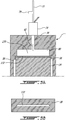
- the outlet 78 of the injector 74 is received in the fluid passage 270 defined through the peripheral wall 38, and located in proximity of the inner surface of the peripheral wall 38 for direct lubricant delivery to each seal 56 as it slides over the opening 272 defined in the inner surface by the fluid passage 270.
- the opening 72, 172, 272 of each fluid passage 70, 170, 270 is positioned after the intake port 48 and before the combustion starts, following the direction of movement of the apex seals 56 upon rotation of the rotor 34, i.e. the seals 56, in order, pass over the intake port 48, pass over the opening(s) 72, 172, 272, and then reach the zone of combustion.
- the opening(s) 72, 172, 272 is/are positioned at any location from point "A" to point "B" as indicated in Fig. 1 . A similar location may also be used for an engine where the intake port is defined through the end wall 54.
- the feed pressure to the injector 74 is adjusted based on the chamber pressure at the location of the opening 72, 172, 272; accordingly, a higher feed pressure may be required if the seal lubricant injection is made later in the compression stroke.
- the opening(s) 72, 172, 272 is/are defined adjacent to and after the intake port 48.
- the seal lubricant may be injected in the top dead center section of the housing 32; however, such positioning may be more complex due to high temperature and pressure and to the presence of the high pressure fuel injection system at this location.
- the seal lubricant Injection may be performed in the expansion stroke of the engine; however, such a configuration may lead to loss of lubricant in the exhaust and/or intake port, particularly when these ports are defined through the peripheral wall. Higher temperatures of the expansion side may also cause coking of the lubricant in the fluid passage 70, 170, 270.
- the injector 74 is or is similar to an injector configured for gasoline direct injection (GDI).
- GDI gasoline direct injection
- FIG. 7 An example of a GDI injector is shown in Fig. 7 , where the inlet 76 is in communication with the outlet 78 through a strainer 82.
- the outlet 78 includes an outlet opening 78' which is selectively closed by a needle 84 biased toward the closed position and movable inwardly to disengage from the perimeter of the outlet opening 78' to open it.
- a seal 86 extends around the outlet portion of the injectors to sealingly engage the adjacent wall surfaces of the housing 32.
- the needle 84 forms part of a solenoid valve: a magnetic coil 88 of the injector housing interacts with a magneto armature 90 connected to the needle to move the needle 84 along its axis between the open and closed configurations of the injector 74.
- Other types of valves may be provided to selectively open and close the outlet opening 78' of the injector 74, including, but not limited to, a piezo activated valve.
- the injector 74 can be precisely activated through electrical actuation of the valve, to select the desired injection frequency and volume.
- GDI injectors can typically be controlled, for example by an engine control unit, to adjust flow and/or frequency of injection based on suitable parameters of the engine, including, but not limited to, injected fluid temperature and pressure, engine speed, engine load (or throttle position), intake manifold pressure, injector body temperature and engine coolant temperature; similar control can be applied to the injector 74 when used for lubricant injection to the seals 56, so that the lubricant injection can be tailored to the operating parameters of the engine.
- the injector 74 thus acts as a metering device allowing control of the quantity, frequency and timing of the lubricant injection to the seals 56.
- Injectors of the type used for gasoline direct injection (GDI) engines typically allow good control over the injection duration, which allows for precise control of the quantity of injected lubricant over the engine operation range.
- the injector 74 is designed to work at a pressure of 30 psia (206.8 kPaa) to 180 psia (1241.1 kPaa), for example at least 60 psia (413.7 kPaa), and/or to inject lubricant at a frequency of up to once per engine revolution and/or at a temperature of at least 120°F (52.8°C) to 250°F (121.1°C).
- a lubrication injection system which may be used with any of the above described engines 12 and injectors 74 is shown.
- This lubrication system uses the lubricant which is circulated to the rotor 34, for example to lubricate bearings rotationally supporting the rotor 34 within the rotor cavity and/or for cooling of the rotor 34, as the lubricant injected to lubricate the seals 56.
- the lubricant is oil.
- the system includes a scavenge pump 92 in each line communicating with one or more of the lubrication cavities of the engine 12, for circulating the used oil back to an oil reservoir 94.
- a main engine oil pump 96 communicates with the oil reservoir 94 and provides pressurized oil to the engine 12.
- the oil circulates through a heat exchanger 98, for example located downstream of the main engine pump 96, so that the used oil can be cooled before being recirculated to the engine 12.
- the oil circulates through a filter 99 to remove contaminants, and is then circulated both to the injector 74 for providing oil to the seals 56 and to the various lubrication cavities of the engine 12 (e.g. bearing cavities).
- Sensors 97 for example located between the oil filter 99 and the injector 74/engine 12, provide relevant data (e.g. oil temperature, oil pressure) which may be used to control the pumps 92, 96 and/or the injector 74.
- the oil used to feed the injector 74 is thus at the main engine oil pressure (MOP), i.e. the pressurization provided by the main engine oil pump 96 is sufficient to feed the injector 74.
- MOP main engine oil pressure
- a lubrication injection system which may be used with any of the above described engines 12 and injectors 74 is shown.
- This lubrication system uses part of the fuel circulated for combustion for injection to lubricate the seals 56.
- the system includes a first stage fuel pump 196 communicating with a fuel reservoir 194 and providing pressurized fuel to the engine 12.
- a second stage pump 192 is provided downstream of the first stage pump 196, with a fuel filter 199 located therebetween to remove contaminants.
- the injector 74 for the seals 56 extracts fuel between the first stage and second stage pumps 196, 192 to use as a lubricant.
- the second stage pump 192 delivers fuel to a fuel injection system 100 (e.g. high pressure common rail injection system) delivering pressurized fuel to the working chambers 40 (and/or to a subchamber communicating with the working chambers) for combustion.
- a fuel injection system 100 e.g. high pressure common rail injection system
- Bypass lines 195 recirculate overflow fuel from the fuel injection system 100 and from the second stage pump 192 to a location upstream of the first stage pump 196 for recirculation.
- Sensors 197 for example located between the fuel reservoir 194 and the first stage pump 196, and between the first stage pump 196 and the injector 74, provide relevant data (e.g. fuel temperature, fuel pressure) which may be used to control the he pumps 92, 96, fuel injection system 100 and/or the injector 74.
- the lubrication injection system may vary.
- the lubrication injection system for feeding the injector 74 for the seals 56 may be independent from the circulation of the other engine fluids, although such an independent system may add weight and/or complexity.
- the scavenge pumps may be omitted.
- injector 74 Although a single injector 74 has been shown, it is understood that more than one injector 74 can alternately be provided.
- the two or more injectors 74 could be located at different angular positions within the housing, for example one to inject seal lubricant after the intake port and another to inject lubricant in the expansion section of the housing.
- the two or more injectors 74 could alternately be located at the same angular position.
- the multiple injectors 74 could be used for direct injection or for injection into a manifold, as described above.
- the present disclosure accordingly allows for lubricating the peripheral or apex seals 56 by circulating lubricant from a pressurized lubricant source (such as pump 96 and oil reservoir 94, or pump 196 and fuel reservoir 194) to the injector 74, selectively opening the outlet 78 of the injector 74, and when the outlet 78 is open, delivering the pressurized lubricant through the housing 32 and to the inner surface of the rotor cavity with the injector 74.
- the seals 56 contact the inner surface upon rotation of the rotor 34 within the rotor cavity, and are accordingly lubricated.
- the pressurized lubricant may be delivered through a manifold 80 defined in the housing 32 or delivered by the injector 74 directly to the seals 56.
- the injector 74 allows metering of the quantity of lubricant being delivered.
- the system described herein allows for a more complete and improved control over the frequency and quantity of delivered lubricant by making use of suitable engine sensor inputs (e.g. lubricant pressure and temperature, engine speed) to define the injection frequency and volume. This is turn may allow for a reduction of lubricant consumption while maintaining the same wear rates and performance of the engine.
- the present system is in a particular embodiment more compact and lightweight, which is crucial for aerospace applications. Emissions of the engine may also be positively influenced through suitable tailoring of the injection parameters. When commercially available GDI injectors are used, the system may allow for a reduction in cost.
- the system also allows for other fluids providing acceptable wear rates to be used as lubricant, for example fuel (heavy fuel, diesel fuel, etc.)
- seal lubricant injection may be applicable to lubricate peripheral seals other than apex seals, in other rotary engines having different types of configuration (e.g. peripheral seals on vanes of a rotary vane pump). Modifications which fall within the scope of the present invention will be apparent to those skilled in the art, in light of a review of this disclosure, and such modifications are intended to fall within the appended claims.
Landscapes
- Engineering & Computer Science (AREA)
- Mechanical Engineering (AREA)
- General Engineering & Computer Science (AREA)
- Chemical & Material Sciences (AREA)
- Combustion & Propulsion (AREA)
- Fuel-Injection Apparatus (AREA)
- Lubrication Of Internal Combustion Engines (AREA)
Priority Applications (1)
| Application Number | Priority Date | Filing Date | Title |
|---|---|---|---|
| PL17176661T PL3258062T3 (pl) | 2016-06-17 | 2017-06-19 | Obrotowy silnik spalinowy ze smarowaniem uszczelnienia |
Applications Claiming Priority (1)
| Application Number | Priority Date | Filing Date | Title |
|---|---|---|---|
| US15/185,544 US10570789B2 (en) | 2016-06-17 | 2016-06-17 | Rotary internal combustion engine with seal lubrication |
Publications (2)
| Publication Number | Publication Date |
|---|---|
| EP3258062A1 true EP3258062A1 (fr) | 2017-12-20 |
| EP3258062B1 EP3258062B1 (fr) | 2021-04-07 |
Family
ID=59091383
Family Applications (1)
| Application Number | Title | Priority Date | Filing Date |
|---|---|---|---|
| EP17176661.1A Active EP3258062B1 (fr) | 2016-06-17 | 2017-06-19 | Moteur rotatif à combustion interne avec lubrification de joint |
Country Status (7)
| Country | Link |
|---|---|
| US (3) | US10570789B2 (fr) |
| EP (1) | EP3258062B1 (fr) |
| CN (1) | CN109312622B (fr) |
| CA (1) | CA2968856C (fr) |
| ES (1) | ES2873257T3 (fr) |
| PL (1) | PL3258062T3 (fr) |
| WO (1) | WO2017214721A1 (fr) |
Cited By (2)
| Publication number | Priority date | Publication date | Assignee | Title |
|---|---|---|---|---|
| EP3789597A1 (fr) * | 2019-09-03 | 2021-03-10 | Pratt & Whitney Canada Corp. | Moteur d'aéronef avec système de carburant à rampe commune comprenant une pompe d'éjecteur et méthode de fonctionnement d'un moteur d'aéronef |
| EP3910164A1 (fr) * | 2020-05-12 | 2021-11-17 | Pratt & Whitney Canada Corp. | Système de lubrification de moteur rotatif à l'aide d'un injecteur intensificateur |
Families Citing this family (6)
| Publication number | Priority date | Publication date | Assignee | Title |
|---|---|---|---|---|
| US10570789B2 (en) | 2016-06-17 | 2020-02-25 | Pratt & Whitney Canada Corp. | Rotary internal combustion engine with seal lubrication |
| WO2018185730A1 (fr) | 2017-04-07 | 2018-10-11 | Stackpole International Engineered Products, Ltd. | Pompe à vide épitrochoïdale |
| WO2022086348A1 (fr) * | 2020-10-23 | 2022-04-28 | Robson David George | Appareil d'entraînement rotatif |
| US11506116B2 (en) | 2020-11-04 | 2022-11-22 | William Todd Hodges | Rotary combustion engine with integrated multistage fuel system |
| US11619165B1 (en) | 2020-11-04 | 2023-04-04 | William Todd Hodges | Rotary combustion engine with integrated multistage fuel system |
| CN114483250B (zh) * | 2022-02-07 | 2023-04-28 | 西安交通大学 | 一种反三角转子发动机强制润滑系统设计方法 |
Citations (5)
| Publication number | Priority date | Publication date | Assignee | Title |
|---|---|---|---|---|
| US3771903A (en) * | 1972-02-01 | 1973-11-13 | R King | Lubricating system for rotary machine |
| US3811806A (en) * | 1972-02-01 | 1974-05-21 | Copeland Refrigeration Corp | Lubricating system for rotary machine |
| US3868929A (en) * | 1972-04-03 | 1975-03-04 | Nissan Motor | Lubricating oil supply system for rotary engine |
| DE2502931A1 (de) * | 1974-01-25 | 1975-07-31 | Siak Hoo Ong | Rotationskolbenmaschine |
| US3990818A (en) * | 1975-02-27 | 1976-11-09 | Curtiss-Wright Corporation | Lubrication system for rotary piston mechanisms |
Family Cites Families (59)
| Publication number | Priority date | Publication date | Assignee | Title |
|---|---|---|---|---|
| US3280812A (en) * | 1966-10-25 | Lubrication of the gastight radial scrapers in rotary engines | ||
| US2778539A (en) * | 1949-09-27 | 1957-01-22 | Daimler Benz Ag | Device for fuel-metering, in particular, fuel-injection for internal combustion engines |
| US3196846A (en) * | 1960-05-05 | 1965-07-27 | Daimler Benz Ag | Rotary piston engine |
| US3098605A (en) * | 1960-05-27 | 1963-07-23 | Curtiss Wright Corp | Cooling and lubrication system for rotary mechanisms |
| DE1201604B (de) * | 1961-02-25 | 1965-09-23 | Daimler Benz Ag | Schmiervorrichtung fuer Rotationskolben-Brennkraftmaschinen |
| US3387595A (en) * | 1962-05-01 | 1968-06-11 | Curtiss Wright Corp | Rotary combustion engine with precombustion chamber |
| US3245386A (en) * | 1962-10-29 | 1966-04-12 | Curtiss Wright Corp | Seal lubrication for rotary engines |
| GB1008745A (en) * | 1963-11-27 | 1965-11-03 | Rolls Royce | Improved rotary piston internal combustion engines |
| US3376951A (en) | 1964-12-29 | 1968-04-09 | Bendix Corp | Means for lubrication of gas vane motors |
| GB1098278A (en) * | 1965-06-19 | 1968-01-10 | Daimler Benz Ag | New or improved lubricating arrangement in a rotary-piston engine |
| DE2042536A1 (de) * | 1970-08-27 | 1972-03-02 | Daimler Benz Ag, 7000 Stuttgart | Rotationskolben Brennkraftmaschine, insbesondere in Trochoidenbauart |
| DE2056673A1 (de) * | 1970-11-18 | 1972-05-25 | Daimler-Benz Ag, 7000 Stuttgart | Rotationskolben-Einspritzbrennkraftmaschine |
| DE2110333A1 (de) * | 1971-03-04 | 1972-09-14 | Audi Nsu Auto Union Ag | Kreiskolben-Brennkraftmaschine |
| US3752607A (en) * | 1972-03-06 | 1973-08-14 | Gen Motors Corp | Rotary machine apex seal |
| US3806021A (en) | 1972-03-17 | 1974-04-23 | P Moroz | Pipe centering apparatus |
| US3764234A (en) * | 1972-06-26 | 1973-10-09 | Gen Motors Corp | Rotary engine oil metering pump |
| US3814555A (en) * | 1972-07-14 | 1974-06-04 | Gen Motors Corp | Rotary engine gas seal lubrication system |
| US3846053A (en) * | 1973-07-16 | 1974-11-05 | S Roberts | Rotary internal combustion engine having dynamic fluid seals |
| US3884601A (en) * | 1973-09-24 | 1975-05-20 | Gen Motors Corp | Rotary engine rotor seal lubrication |
| US3886914A (en) | 1973-12-14 | 1975-06-03 | Ford Motor Co | Lubricant metering system |
| US3888606A (en) * | 1973-12-26 | 1975-06-10 | Ford Motor Co | Rotary internal combustion engine |
| US3923434A (en) * | 1974-07-10 | 1975-12-02 | Gen Motors Corp | Rotary combustion engine apex seal lubrication |
| US3913706A (en) * | 1974-08-06 | 1975-10-21 | Ford Motor Co | Pressure lubrication to apex corner seal |
| US3929117A (en) * | 1974-10-29 | 1975-12-30 | Gen Motors Corp | Rotary engine oil tank vent |
| DE2500957C3 (de) * | 1975-01-11 | 1978-10-26 | Audi Nsu Auto Union Ag, 7107 Neckarsulm | Rotationskolben-Brennkraftmaschine in Trochoidenbauart |
| US3976404A (en) * | 1975-02-19 | 1976-08-24 | Caterpillar Tractor Co. | Lubrication of compression seals in rotary engines |
| DE2512425A1 (de) | 1975-03-21 | 1976-10-07 | Audi Nsu Auto Union Ag | Fluessigkeitskuehlung fuer den kolben einer rotationskolbenmaschine |
| US4106169A (en) * | 1975-09-12 | 1978-08-15 | Caterpillar Tractor Co. | Seal lubrication in a rotary engine |
| US3990819A (en) * | 1975-09-26 | 1976-11-09 | Caterpillar Tractor Co. | Seals for rotary mechanisms |
| US4072449A (en) * | 1976-03-12 | 1978-02-07 | Caterpillar Tractor Co. | Combined seal biasing spring and check valve for rotary mechanisms |
| US4026612A (en) * | 1976-03-22 | 1977-05-31 | Caterpillar Tractor Co. | Lubrication of seals in rotary mechanisms |
| DE2621720B2 (de) * | 1976-05-15 | 1981-04-23 | Audi Nsu Auto Union Ag, 7107 Neckarsulm | Flüssigkeitsgekühlter mehreckiger Kolben einer Rotationskolbenmaschine in Trochoidenbauart |
| JPS5634904A (en) * | 1979-08-27 | 1981-04-07 | Mazda Motor Corp | Lubricating oil feeder for rotary piston engine |
| US4345885A (en) * | 1980-03-03 | 1982-08-24 | Briggs & Stratton Corporation | Lubrication system for rotary-trochoidal engines |
| US4463718A (en) * | 1982-11-01 | 1984-08-07 | Deere & Company | Lubricant metering system for rotary internal combustion engine |
| US4760701A (en) * | 1984-03-06 | 1988-08-02 | David Constant V | External combustion rotary engine |
| JPS62276208A (ja) * | 1986-01-20 | 1987-12-01 | Mazda Motor Corp | エンジンの潤滑装置 |
| US4774918A (en) | 1986-01-24 | 1988-10-04 | Mazda Motor Corporation | Engine lubricating system |
| US5305721A (en) * | 1989-06-29 | 1994-04-26 | Burtis Wilson A | Rotary Wankel type engine |
| US5203307A (en) * | 1989-06-29 | 1993-04-20 | Burtis Wilson A | Rotary wankel type engine |
| US4969429A (en) * | 1989-10-02 | 1990-11-13 | John Deere Technologies International, Inc. | Lube oil control system for turbocharged rotary piston engine |
| US6164942A (en) | 1997-12-24 | 2000-12-26 | Moller International | Rotary engine having enhanced charge cooling and lubrication |
| US6325603B1 (en) * | 1998-12-17 | 2001-12-04 | Moller International, Inc. | Charged cooled rotary engine |
| US8365698B2 (en) * | 2004-01-12 | 2013-02-05 | Liquidpiston, Inc. | Hybrid cycle combustion engine and methods |
| IL170165A (en) * | 2005-08-08 | 2010-12-30 | Haim Rom | Wankel and similar rotary engines |
| US7343894B2 (en) * | 2005-10-16 | 2008-03-18 | Enrique Haluy Leon | Modular rotary engine |
| US8602166B2 (en) * | 2006-01-05 | 2013-12-10 | Sikorsky Aircraft Corporation | Secondary lubrication system with injectable additive |
| EP2132411A4 (fr) | 2007-04-09 | 2014-11-05 | Seth Chandan Kumar | Moteur split-cycle (à cycle scindé) à allumage commandé rotatif et capacité variable |
| US8985085B2 (en) * | 2011-07-28 | 2015-03-24 | Pratt & Whitney Canada Corp. | Oil seal arrangement for rotary internal combustion engine |
| US9334766B2 (en) | 2011-09-27 | 2016-05-10 | GM Global Technology Operations LLC | Method and apparatus for controlling oil flow in an internal combustion engine |
| GB201118247D0 (en) * | 2011-10-23 | 2011-12-07 | Compound Rotary Engines Ltd | Rotary piston internal combustion engine |
| US8977477B2 (en) | 2012-10-04 | 2015-03-10 | Ford Global Technologies, Llc | Approach for controlling operation of oil injectors |
| US9464566B2 (en) * | 2013-07-24 | 2016-10-11 | Ned M Ahdoot | Plural blade rotary engine |
| JP5854022B2 (ja) | 2013-10-04 | 2016-02-09 | トヨタ自動車株式会社 | 内燃機関のオイルジェット装置 |
| US9896934B2 (en) | 2013-12-17 | 2018-02-20 | Pratt & Whitney Canada Corp. | Rotary engine with rotor land |
| CN104775900B (zh) * | 2014-01-13 | 2019-08-20 | 普拉特-惠特尼加拿大公司 | 复合循环发动机 |
| US10717541B2 (en) * | 2015-02-19 | 2020-07-21 | Orbital Australia Pty Ltd | UAV fuel and lubrication system |
| US10570789B2 (en) | 2016-06-17 | 2020-02-25 | Pratt & Whitney Canada Corp. | Rotary internal combustion engine with seal lubrication |
| US20190301361A1 (en) * | 2018-03-27 | 2019-10-03 | Kan Cheng | Fuel-air injection rotary engine |
-
2016
- 2016-06-17 US US15/185,544 patent/US10570789B2/en active Active
-
2017
- 2017-05-29 CA CA2968856A patent/CA2968856C/fr active Active
- 2017-06-13 CN CN201780037714.1A patent/CN109312622B/zh active Active
- 2017-06-13 WO PCT/CA2017/050724 patent/WO2017214721A1/fr not_active Ceased
- 2017-06-19 ES ES17176661T patent/ES2873257T3/es active Active
- 2017-06-19 PL PL17176661T patent/PL3258062T3/pl unknown
- 2017-06-19 EP EP17176661.1A patent/EP3258062B1/fr active Active
-
2020
- 2020-01-23 US US16/750,431 patent/US11008909B2/en active Active
-
2021
- 2021-04-14 US US17/229,964 patent/US11428128B2/en active Active
Patent Citations (5)
| Publication number | Priority date | Publication date | Assignee | Title |
|---|---|---|---|---|
| US3771903A (en) * | 1972-02-01 | 1973-11-13 | R King | Lubricating system for rotary machine |
| US3811806A (en) * | 1972-02-01 | 1974-05-21 | Copeland Refrigeration Corp | Lubricating system for rotary machine |
| US3868929A (en) * | 1972-04-03 | 1975-03-04 | Nissan Motor | Lubricating oil supply system for rotary engine |
| DE2502931A1 (de) * | 1974-01-25 | 1975-07-31 | Siak Hoo Ong | Rotationskolbenmaschine |
| US3990818A (en) * | 1975-02-27 | 1976-11-09 | Curtiss-Wright Corporation | Lubrication system for rotary piston mechanisms |
Cited By (3)
| Publication number | Priority date | Publication date | Assignee | Title |
|---|---|---|---|---|
| EP3789597A1 (fr) * | 2019-09-03 | 2021-03-10 | Pratt & Whitney Canada Corp. | Moteur d'aéronef avec système de carburant à rampe commune comprenant une pompe d'éjecteur et méthode de fonctionnement d'un moteur d'aéronef |
| US11092126B2 (en) | 2019-09-03 | 2021-08-17 | Pratt & Whitney Canada Corp. | Common-rail fuel system with ejector pump and method of use thereof |
| EP3910164A1 (fr) * | 2020-05-12 | 2021-11-17 | Pratt & Whitney Canada Corp. | Système de lubrification de moteur rotatif à l'aide d'un injecteur intensificateur |
Also Published As
| Publication number | Publication date |
|---|---|
| US11008909B2 (en) | 2021-05-18 |
| CA2968856A1 (fr) | 2017-12-17 |
| ES2873257T3 (es) | 2021-11-03 |
| US10570789B2 (en) | 2020-02-25 |
| US20200157985A1 (en) | 2020-05-21 |
| US11428128B2 (en) | 2022-08-30 |
| US20170362974A1 (en) | 2017-12-21 |
| CN109312622A (zh) | 2019-02-05 |
| PL3258062T3 (pl) | 2021-09-20 |
| EP3258062B1 (fr) | 2021-04-07 |
| US20210231033A1 (en) | 2021-07-29 |
| CN109312622B (zh) | 2021-09-21 |
| CA2968856C (fr) | 2025-09-02 |
| WO2017214721A1 (fr) | 2017-12-21 |
Similar Documents
| Publication | Publication Date | Title |
|---|---|---|
| US11428128B2 (en) | Rotary internal combustion engine with seal lubrication | |
| US9957885B2 (en) | Internal combustion engine with common rail pilot and main injection | |
| US9708966B2 (en) | Internal combustion engine with pilot and main injection | |
| US11111848B1 (en) | Fuel injection system for aircraft engine | |
| US10072559B2 (en) | Method of operating an engine having a pilot subchamber at partial load conditions | |
| US11306651B2 (en) | Method of operating an internal combustion engine | |
| US10865728B2 (en) | Method of using backflow from common-rail fuel injector | |
| CA3253805A1 (en) | Rotary internal combustion engine with seal lubrication | |
| US11174732B1 (en) | Rotary engine lubrication system using intensifier injector |
Legal Events
| Date | Code | Title | Description |
|---|---|---|---|
| PUAI | Public reference made under article 153(3) epc to a published international application that has entered the european phase |
Free format text: ORIGINAL CODE: 0009012 |
|
| STAA | Information on the status of an ep patent application or granted ep patent |
Free format text: STATUS: THE APPLICATION HAS BEEN PUBLISHED |
|
| AK | Designated contracting states |
Kind code of ref document: A1 Designated state(s): AL AT BE BG CH CY CZ DE DK EE ES FI FR GB GR HR HU IE IS IT LI LT LU LV MC MK MT NL NO PL PT RO RS SE SI SK SM TR |
|
| AX | Request for extension of the european patent |
Extension state: BA ME |
|
| STAA | Information on the status of an ep patent application or granted ep patent |
Free format text: STATUS: REQUEST FOR EXAMINATION WAS MADE |
|
| 17P | Request for examination filed |
Effective date: 20180620 |
|
| RBV | Designated contracting states (corrected) |
Designated state(s): AL AT BE BG CH CY CZ DE DK EE ES FI FR GB GR HR HU IE IS IT LI LT LU LV MC MK MT NL NO PL PT RO RS SE SI SK SM TR |
|
| STAA | Information on the status of an ep patent application or granted ep patent |
Free format text: STATUS: EXAMINATION IS IN PROGRESS |
|
| 17Q | First examination report despatched |
Effective date: 20190417 |
|
| GRAP | Despatch of communication of intention to grant a patent |
Free format text: ORIGINAL CODE: EPIDOSNIGR1 |
|
| STAA | Information on the status of an ep patent application or granted ep patent |
Free format text: STATUS: GRANT OF PATENT IS INTENDED |
|
| INTG | Intention to grant announced |
Effective date: 20201023 |
|
| GRAS | Grant fee paid |
Free format text: ORIGINAL CODE: EPIDOSNIGR3 |
|
| GRAA | (expected) grant |
Free format text: ORIGINAL CODE: 0009210 |
|
| STAA | Information on the status of an ep patent application or granted ep patent |
Free format text: STATUS: THE PATENT HAS BEEN GRANTED |
|
| AK | Designated contracting states |
Kind code of ref document: B1 Designated state(s): AL AT BE BG CH CY CZ DE DK EE ES FI FR GB GR HR HU IE IS IT LI LT LU LV MC MK MT NL NO PL PT RO RS SE SI SK SM TR |
|
| REG | Reference to a national code |
Ref country code: GB Ref legal event code: FG4D |
|
| REG | Reference to a national code |
Ref country code: AT Ref legal event code: REF Ref document number: 1379923 Country of ref document: AT Kind code of ref document: T Effective date: 20210415 Ref country code: CH Ref legal event code: EP |
|
| REG | Reference to a national code |
Ref country code: DE Ref legal event code: R096 Ref document number: 602017036032 Country of ref document: DE |
|
| REG | Reference to a national code |
Ref country code: IE Ref legal event code: FG4D |
|
| REG | Reference to a national code |
Ref country code: LT Ref legal event code: MG9D |
|
| REG | Reference to a national code |
Ref country code: NL Ref legal event code: MP Effective date: 20210407 |
|
| PG25 | Lapsed in a contracting state [announced via postgrant information from national office to epo] |
Ref country code: FI Free format text: LAPSE BECAUSE OF FAILURE TO SUBMIT A TRANSLATION OF THE DESCRIPTION OR TO PAY THE FEE WITHIN THE PRESCRIBED TIME-LIMIT Effective date: 20210407 Ref country code: LT Free format text: LAPSE BECAUSE OF FAILURE TO SUBMIT A TRANSLATION OF THE DESCRIPTION OR TO PAY THE FEE WITHIN THE PRESCRIBED TIME-LIMIT Effective date: 20210407 Ref country code: HR Free format text: LAPSE BECAUSE OF FAILURE TO SUBMIT A TRANSLATION OF THE DESCRIPTION OR TO PAY THE FEE WITHIN THE PRESCRIBED TIME-LIMIT Effective date: 20210407 Ref country code: BG Free format text: LAPSE BECAUSE OF FAILURE TO SUBMIT A TRANSLATION OF THE DESCRIPTION OR TO PAY THE FEE WITHIN THE PRESCRIBED TIME-LIMIT Effective date: 20210707 Ref country code: NL Free format text: LAPSE BECAUSE OF FAILURE TO SUBMIT A TRANSLATION OF THE DESCRIPTION OR TO PAY THE FEE WITHIN THE PRESCRIBED TIME-LIMIT Effective date: 20210407 |
|
| REG | Reference to a national code |
Ref country code: ES Ref legal event code: FG2A Ref document number: 2873257 Country of ref document: ES Kind code of ref document: T3 Effective date: 20211103 |
|
| PG25 | Lapsed in a contracting state [announced via postgrant information from national office to epo] |
Ref country code: NO Free format text: LAPSE BECAUSE OF FAILURE TO SUBMIT A TRANSLATION OF THE DESCRIPTION OR TO PAY THE FEE WITHIN THE PRESCRIBED TIME-LIMIT Effective date: 20210707 Ref country code: PT Free format text: LAPSE BECAUSE OF FAILURE TO SUBMIT A TRANSLATION OF THE DESCRIPTION OR TO PAY THE FEE WITHIN THE PRESCRIBED TIME-LIMIT Effective date: 20210809 Ref country code: RS Free format text: LAPSE BECAUSE OF FAILURE TO SUBMIT A TRANSLATION OF THE DESCRIPTION OR TO PAY THE FEE WITHIN THE PRESCRIBED TIME-LIMIT Effective date: 20210407 Ref country code: SE Free format text: LAPSE BECAUSE OF FAILURE TO SUBMIT A TRANSLATION OF THE DESCRIPTION OR TO PAY THE FEE WITHIN THE PRESCRIBED TIME-LIMIT Effective date: 20210407 Ref country code: LV Free format text: LAPSE BECAUSE OF FAILURE TO SUBMIT A TRANSLATION OF THE DESCRIPTION OR TO PAY THE FEE WITHIN THE PRESCRIBED TIME-LIMIT Effective date: 20210407 Ref country code: IS Free format text: LAPSE BECAUSE OF FAILURE TO SUBMIT A TRANSLATION OF THE DESCRIPTION OR TO PAY THE FEE WITHIN THE PRESCRIBED TIME-LIMIT Effective date: 20210807 Ref country code: GR Free format text: LAPSE BECAUSE OF FAILURE TO SUBMIT A TRANSLATION OF THE DESCRIPTION OR TO PAY THE FEE WITHIN THE PRESCRIBED TIME-LIMIT Effective date: 20210708 |
|
| REG | Reference to a national code |
Ref country code: DE Ref legal event code: R097 Ref document number: 602017036032 Country of ref document: DE |
|
| PG25 | Lapsed in a contracting state [announced via postgrant information from national office to epo] |
Ref country code: MC Free format text: LAPSE BECAUSE OF FAILURE TO SUBMIT A TRANSLATION OF THE DESCRIPTION OR TO PAY THE FEE WITHIN THE PRESCRIBED TIME-LIMIT Effective date: 20210407 Ref country code: DK Free format text: LAPSE BECAUSE OF FAILURE TO SUBMIT A TRANSLATION OF THE DESCRIPTION OR TO PAY THE FEE WITHIN THE PRESCRIBED TIME-LIMIT Effective date: 20210407 Ref country code: EE Free format text: LAPSE BECAUSE OF FAILURE TO SUBMIT A TRANSLATION OF THE DESCRIPTION OR TO PAY THE FEE WITHIN THE PRESCRIBED TIME-LIMIT Effective date: 20210407 Ref country code: RO Free format text: LAPSE BECAUSE OF FAILURE TO SUBMIT A TRANSLATION OF THE DESCRIPTION OR TO PAY THE FEE WITHIN THE PRESCRIBED TIME-LIMIT Effective date: 20210407 Ref country code: SK Free format text: LAPSE BECAUSE OF FAILURE TO SUBMIT A TRANSLATION OF THE DESCRIPTION OR TO PAY THE FEE WITHIN THE PRESCRIBED TIME-LIMIT Effective date: 20210407 Ref country code: SM Free format text: LAPSE BECAUSE OF FAILURE TO SUBMIT A TRANSLATION OF THE DESCRIPTION OR TO PAY THE FEE WITHIN THE PRESCRIBED TIME-LIMIT Effective date: 20210407 |
|
| PLBE | No opposition filed within time limit |
Free format text: ORIGINAL CODE: 0009261 |
|
| STAA | Information on the status of an ep patent application or granted ep patent |
Free format text: STATUS: NO OPPOSITION FILED WITHIN TIME LIMIT |
|
| REG | Reference to a national code |
Ref country code: BE Ref legal event code: MM Effective date: 20210630 |
|
| 26N | No opposition filed |
Effective date: 20220110 |
|
| PG25 | Lapsed in a contracting state [announced via postgrant information from national office to epo] |
Ref country code: LU Free format text: LAPSE BECAUSE OF NON-PAYMENT OF DUE FEES Effective date: 20210619 |
|
| PG25 | Lapsed in a contracting state [announced via postgrant information from national office to epo] |
Ref country code: IE Free format text: LAPSE BECAUSE OF NON-PAYMENT OF DUE FEES Effective date: 20210619 |
|
| PG25 | Lapsed in a contracting state [announced via postgrant information from national office to epo] |
Ref country code: IS Free format text: LAPSE BECAUSE OF FAILURE TO SUBMIT A TRANSLATION OF THE DESCRIPTION OR TO PAY THE FEE WITHIN THE PRESCRIBED TIME-LIMIT Effective date: 20210807 Ref country code: AL Free format text: LAPSE BECAUSE OF FAILURE TO SUBMIT A TRANSLATION OF THE DESCRIPTION OR TO PAY THE FEE WITHIN THE PRESCRIBED TIME-LIMIT Effective date: 20210407 |
|
| PG25 | Lapsed in a contracting state [announced via postgrant information from national office to epo] |
Ref country code: BE Free format text: LAPSE BECAUSE OF NON-PAYMENT OF DUE FEES Effective date: 20210630 |
|
| REG | Reference to a national code |
Ref country code: AT Ref legal event code: UEP Ref document number: 1379923 Country of ref document: AT Kind code of ref document: T Effective date: 20210407 |
|
| PG25 | Lapsed in a contracting state [announced via postgrant information from national office to epo] |
Ref country code: HU Free format text: LAPSE BECAUSE OF FAILURE TO SUBMIT A TRANSLATION OF THE DESCRIPTION OR TO PAY THE FEE WITHIN THE PRESCRIBED TIME-LIMIT; INVALID AB INITIO Effective date: 20170619 |
|
| PG25 | Lapsed in a contracting state [announced via postgrant information from national office to epo] |
Ref country code: CY Free format text: LAPSE BECAUSE OF FAILURE TO SUBMIT A TRANSLATION OF THE DESCRIPTION OR TO PAY THE FEE WITHIN THE PRESCRIBED TIME-LIMIT Effective date: 20210407 |
|
| P01 | Opt-out of the competence of the unified patent court (upc) registered |
Effective date: 20230530 |
|
| PG25 | Lapsed in a contracting state [announced via postgrant information from national office to epo] |
Ref country code: MK Free format text: LAPSE BECAUSE OF FAILURE TO SUBMIT A TRANSLATION OF THE DESCRIPTION OR TO PAY THE FEE WITHIN THE PRESCRIBED TIME-LIMIT Effective date: 20210407 |
|
| PG25 | Lapsed in a contracting state [announced via postgrant information from national office to epo] |
Ref country code: MT Free format text: LAPSE BECAUSE OF FAILURE TO SUBMIT A TRANSLATION OF THE DESCRIPTION OR TO PAY THE FEE WITHIN THE PRESCRIBED TIME-LIMIT Effective date: 20210407 |
|
| PGFP | Annual fee paid to national office [announced via postgrant information from national office to epo] |
Ref country code: PL Payment date: 20250522 Year of fee payment: 9 Ref country code: DE Payment date: 20250520 Year of fee payment: 9 |
|
| PGFP | Annual fee paid to national office [announced via postgrant information from national office to epo] |
Ref country code: GB Payment date: 20250520 Year of fee payment: 9 |
|
| PGFP | Annual fee paid to national office [announced via postgrant information from national office to epo] |
Ref country code: IT Payment date: 20250520 Year of fee payment: 9 |
|
| PGFP | Annual fee paid to national office [announced via postgrant information from national office to epo] |
Ref country code: FR Payment date: 20250520 Year of fee payment: 9 |
|
| PGFP | Annual fee paid to national office [announced via postgrant information from national office to epo] |
Ref country code: AT Payment date: 20250522 Year of fee payment: 9 |
|
| PGFP | Annual fee paid to national office [announced via postgrant information from national office to epo] |
Ref country code: CZ Payment date: 20250529 Year of fee payment: 9 |
|
| PGFP | Annual fee paid to national office [announced via postgrant information from national office to epo] |
Ref country code: ES Payment date: 20250701 Year of fee payment: 9 |
|
| PGFP | Annual fee paid to national office [announced via postgrant information from national office to epo] |
Ref country code: CH Payment date: 20250701 Year of fee payment: 9 |
|
| PG25 | Lapsed in a contracting state [announced via postgrant information from national office to epo] |
Ref country code: TR Free format text: LAPSE BECAUSE OF FAILURE TO SUBMIT A TRANSLATION OF THE DESCRIPTION OR TO PAY THE FEE WITHIN THE PRESCRIBED TIME-LIMIT Effective date: 20210407 |