EP3258065A1 - Aube de turbine avec plateforme refroidie et turbomachine associée - Google Patents
Aube de turbine avec plateforme refroidie et turbomachine associée Download PDFInfo
- Publication number
- EP3258065A1 EP3258065A1 EP16175024.5A EP16175024A EP3258065A1 EP 3258065 A1 EP3258065 A1 EP 3258065A1 EP 16175024 A EP16175024 A EP 16175024A EP 3258065 A1 EP3258065 A1 EP 3258065A1
- Authority
- EP
- European Patent Office
- Prior art keywords
- blade
- cooling fluid
- turbine
- cooling
- platform
- Prior art date
- Legal status (The legal status is an assumption and is not a legal conclusion. Google has not performed a legal analysis and makes no representation as to the accuracy of the status listed.)
- Withdrawn
Links
Images


Classifications
-
- F—MECHANICAL ENGINEERING; LIGHTING; HEATING; WEAPONS; BLASTING
- F01—MACHINES OR ENGINES IN GENERAL; ENGINE PLANTS IN GENERAL; STEAM ENGINES
- F01D—NON-POSITIVE DISPLACEMENT MACHINES OR ENGINES, e.g. STEAM TURBINES
- F01D5/00—Blades; Blade-carrying members; Heating, heat-insulating, cooling or antivibration means on the blades or the members
- F01D5/12—Blades
- F01D5/14—Form or construction
- F01D5/18—Hollow blades, i.e. blades with cooling or heating channels or cavities; Heating, heat-insulating or cooling means on blades
- F01D5/187—Convection cooling
-
- F—MECHANICAL ENGINEERING; LIGHTING; HEATING; WEAPONS; BLASTING
- F05—INDEXING SCHEMES RELATING TO ENGINES OR PUMPS IN VARIOUS SUBCLASSES OF CLASSES F01-F04
- F05D—INDEXING SCHEME FOR ASPECTS RELATING TO NON-POSITIVE-DISPLACEMENT MACHINES OR ENGINES, GAS-TURBINES OR JET-PROPULSION PLANTS
- F05D2220/00—Application
- F05D2220/30—Application in turbines
- F05D2220/32—Application in turbines in gas turbines
- F05D2220/321—Application in turbines in gas turbines for a special turbine stage
- F05D2220/3212—Application in turbines in gas turbines for a special turbine stage the first stage of a turbine
-
- F—MECHANICAL ENGINEERING; LIGHTING; HEATING; WEAPONS; BLASTING
- F05—INDEXING SCHEMES RELATING TO ENGINES OR PUMPS IN VARIOUS SUBCLASSES OF CLASSES F01-F04
- F05D—INDEXING SCHEME FOR ASPECTS RELATING TO NON-POSITIVE-DISPLACEMENT MACHINES OR ENGINES, GAS-TURBINES OR JET-PROPULSION PLANTS
- F05D2240/00—Components
- F05D2240/80—Platforms for stationary or moving blades
- F05D2240/81—Cooled platforms
Definitions
- the invention relates to a turbine blade for a turbomachine, in particular blade for a gas turbine, with a blade platform, an airfoil, which protrudes from an upper side of the blade platform, and a blade root, which protrudes from an underside of the blade platform, wherein the blade platform has two oppositely disposed side surfaces each extending from an upstream side of the turbine blade to a downstream side of the turbine blade, and in the interior of the blade platform at least one cooling fluid channel is formed, which extends from a cavity in the blade root to a cavity in the airfoil. Furthermore, the invention relates to a turbomachine with turbine blades according to the invention.
- Such turbine blades are known in the prior art in different embodiments and are used in turbomachines to convert the thermal and kinetic energy of a working fluid, in particular a hot gas into rotational energy.
- a turbine blade includes an airfoil that protrudes from an upper surface of the airfoil platform and a blade root that protrudes from an underside of the airfoil platform to secure the turbine blade in the turbomachine.
- turbomachines such as gas turbine engines, include a housing in which a flow passage extends in an axial direction.
- a plurality of turbine stages are arranged one behind the other in the axial direction and spaced from each other.
- Each turbine stage includes a plurality of turbine blades having a vane ring connected to the housing and a turbine blade ring a rotor blade connected centrally and connected to the housing in the axial direction passing runner.
- the flow channel of the gas turbine is flowed through by a hot gas.
- the expanding hot gas flowing through the flow channel is then deflected by the guide vanes in such a way that it optimally flows against the rotor blades arranged behind it.
- the torque generated by the hot gas by means of the blades puts the rotor in rotation. This rotational energy can then be converted into electrical energy, for example by means of a generator.
- thermodynamic efficiency of a gas turbine is higher, the higher the inlet temperature of the hot gas is in the gas turbine.
- the height of the inlet temperature is limited, inter alia, by the thermal load capacity of the turbine blades. Accordingly, an object is to provide turbine blades, which have sufficient mechanical stability for the operation of the gas turbine even at very high temperatures of the hot gas.
- turbine blades are usually provided with elaborate coating systems.
- a further increase in the allowable inlet temperature of the hot gas during operation of the gas turbine can be achieved by cooling the turbine blades.
- cavities for a cooling fluid are provided in the airfoils and the blade roots, which are interconnected by cooling fluid channels which extend from the cavities in the blade root to the cavities in the airfoils.
- a cooling fluid flows through the blade root and the blade platform into the airfoil, for example by impingement cooling the cooling fluid is guided such that it impinges on the wall of the airfoil from the inside, and / or cooled by film cooling, the cooling fluid forming a cooling film on the outside of the airfoil.
- the blade platforms which usually have two oppositely disposed side surfaces, each extending from an upstream side of the turbine blade to a downstream side of the turbine blade, are cooled during operation of the gas turbine.
- the cooling of the side surfaces takes place in that cooling fluid is introduced into the intermediate spaces of the blade platforms arranged adjacent in a turbine blade ring.
- the gaps are closed by so-called sealing wires.
- the sealing wires have transversely to their longitudinal direction passages through which the cooling fluid can escape from the interstices in the flow channel.
- a turbine blade of the type mentioned in the blade platform at least one Cooling fluid hole is formed, which extends from the at least one cooling fluid channel to one of the two side surfaces and opens into them to form an outlet opening.
- the invention is based on the idea of additionally cooling the side surfaces of the blade platform by means of convective cooling and impingement cooling.
- one or more cooling fluid bores are provided in the blade platform which, starting from a cooling fluid channel defined in the blade platform, extend to one of the two side surfaces of the blade platform and open into them to form an outlet opening.
- the cooling fluid flowing through the cooling fluid bores provides for convective cooling of the blade platform, and the cooling fluid flowing out of the exit port of the cooling fluid bore impinges on the side surface of a designated adjacent blade platform, thereby experiencing impingement cooling.
- a further advantage of the turbine blade according to the invention is that the cooling fluid of a cooling region flowing out of the outlet openings and impinging on the side surface of an adjacent blade platform prevents the hot working fluid from penetrating into the space between the two adjacent blade platforms, thereby further reducing the corrosion of the corresponding side surface areas becomes.
- one of the two side surfaces is assigned a group of several, in particular at least three and at most eight cooling fluid bores formed in the blade platform, which extend from the at least one cooling fluid channel to the side surface, wherein the outlet openings of the cooling fluid bores form a cooling region on the Define assigned side surface.
- each of the two side surfaces may each be assigned a group of several, in particular at least three and at most eight cooling fluid bores formed in the blade platform, which extend from the at least one cooling fluid channel to the associated side surface, the outlet openings of the groups of cooling fluid bores each define a cooling area on the associated side surface.
- Two thus arranged groups of cooling fluid bores in each blade platform allow for mutual baffle cooling of mutually facing side surfaces of intended adjacent blade platforms.
- the blade platform can be convectively cooled on both sides of a central axis extending from the inflow side to the outflow side through the blade platform.
- the two cooling regions are arranged at the same height in relation to a center axis extending from the inflow side to the outflow side through the blade platform.
- the blade platform preferably has the shape of a parallelogram or a rectangle, and the two groups of cooling fluid bores are formed such that the mutually facing cooling regions of two identically adjacent blade platforms arranged in the same direction are arranged side by side in the longitudinal direction of the side surfaces and in particular form a coherent cooling region with each other.
- the blade platform in a conventional manner has a base in the form of a parallelogram and their opposite cooling regions relative to the central axis of a blade platform are arranged at the same height, the mutually facing cooling regions of two adjacent arranged identically arranged blade platforms in the longitudinal direction of the side surfaces next to each other be arranged, whereby a larger contiguous cooling area is created between the adjacently arranged identical blade platforms.
- the mutually facing cooling regions adjacent arranged blade platforms complement each other so that in each of the adjacent blade platforms fewer cooling fluid bores are needed to jointly achieve a predetermined effect.
- each cooling region is arranged in a central longitudinal section of the side surface, which extends from the inflow side starting from 40% of the length of the side surface to 80% of the length of the side surface, and / or arranged in a front longitudinal section of the side surface, which is measured from the inflow side extends from the inflow side to 40% of the length of the side surface.
- a generally non-uniform dynamic pressure distribution of the working fluid over the blade platform occurs, which often causes hot working fluid to penetrate the intermediate space between adjacent blade platforms in a central longitudinal section of the side surfaces.
- An arrangement of the cooling regions in the central portion of the side surfaces may at least partially prevent this as a result of a corresponding blocking effect.
- a plurality of cooling fluid passages are formed in the interior of the blade platform, and the cooling fluid bores extend from different ones Cooling fluid channels to the respective associated side surfaces.
- cooling fluid bores of short length can be provided in a simple manner such that the cooling region defined by them encompasses the entire cooling-requiring side surface section of the blade platform. If the cooling fluid bores are assigned to different cooling fluid circuits, cooling fluid of various cooling circuits for cooling the gaps between adjacent blade platforms can also be used in this embodiment.
- the ratio of the spacing of the outlet openings of adjacent cooling fluid bores of a group or each group to their respective diameters is in the range from 10 to 20, wherein a diameter of a cooling fluid bore is defined as the diameter of the smallest circle circumscribed in its cross-sectional contour. This ensures a sufficient density of the exit openings in the side surface of the blade platform to provide an effective cooling area for impingement cooling of the side surface of the adjacent intended turbine blade.
- the outlet openings of the cooling fluid bores of a group or each group are arranged equidistantly and / or the centers of the outlet openings of the cooling fluid bores of a group or each group are arranged on a straight line.
- a uniform impingement cooling is achieved.
- Line-like juxtaposed outlet openings cause a kind of cooling fluid wall to form in the space between adjacent blade platforms, which can reduce or prevent penetration of the hot working fluid into the gap.
- the cooling fluid bores of a group or each group may advantageously extend in a straight line and parallel to one another in the blade platform.
- Such cooling fluid bores are particularly easy to manufacture and provide the shortest connection between the at least one cooling fluid channel and The outlet opening, have the lowest possible flow resistance and thus enable efficient impingement cooling.
- Parallelism of the cooling fluid bores is above all advantageous in terms of convective cooling, since it ensures uniform heat removal from the blade platform.
- the turbine blade according to the invention can be further developed by forming a groove in one or each side surface into which cooling fluid bores open.
- the cooling fluid flowing out of the outlet openings can first collect in the groove in order to form a planar cooling fluid wall in the intermediate space.
- each cooling fluid bore (11) has a circular or elliptical cross-sectional contour.
- Such cross-sectional contours can be formed with standard drilling methods such as EDM (EDM) particularly simple.
- EDM EDM
- round cross-sectional contours over angular have the advantage that the inner surfaces of the cooling fluid bores have no areas of greatly increased thermal material stress, as they can occur, for example, in angular cooling fluid bores in the corner areas.
- each cooling fluid bore has a diameter of at most 2 mm and preferably of 1 mm, wherein the diameter is defined as the diameter of the smallest circumscribed circle of its circumference contour and in particular the ratio of their diameter to their length in the range of 0.2 to 0.7 is. Coolant fluid wells of such diameters are usually also formed in the airfoil. The specified diameter-length ratio ensures that a sufficiently uniform convective cooling effect is achieved in the blade platform.
- each cooling fluid bore extends straight through the blade platform and / or discharges each cooling fluid bore perpendicular to the side surface or its mouth direction is inclined by at most 10 ° relative to the vertical.
- the cooling fluid flowing out of the outlet openings essentially meets the side surface arranged in the opposite direction as intended, thereby ensuring high efficiency of the impingement cooling.
- the present invention provides a turbomachine with turbine blades according to the invention, wherein, in particular in a flow direction of a working fluid, front turbine stages of the turbomachine, in particular the first and / or the second turbine stage, have turbine blades according to the invention.
- Turbine blades according to the invention can increase the thermal load capacity of blade rings, in particular of the front turbine stages, and thereby enable greater maintenance intervals of the turbomachine, thereby increasing their cost-effectiveness.
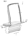
- FIGS. 1 to 4 show a turbine blade 1 for a turbomachine according to an embodiment of the present invention, which is a guide vane of a gas turbine.
- the turbine blade 1 comprises a blade platform 2 and an airfoil 3, which protrudes from an upper side of the blade platform 2.
- the turbine blade 1 comprises a blade root 4, which protrudes in opposite directions from an underside of the blade platform 2.
- each cavities (not shown) are formed for a cooling fluid, which are interconnected by a cooling fluid channel 5 extending from the cavity in the blade root 4 through the blade platform 2 to the cavity in the airfoil 3 extends.
- the blade platform 2 has a base in the form of an elongated parallelogram defining a longitudinal direction L.
- the blade platform 2 also has two side surfaces 6, 7 arranged opposite one another, which each extend from an inflow side 8 of the turbine blade 1 to an outflow side 9 of the turbine blade 1.
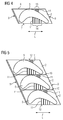
- a plurality of turbine blades 1 in the form of a blade ring are arranged such that intermediate spaces 10 are formed between facing side surfaces 6, 7 of blade platforms 2 arranged adjacent to one another.
- two groups of four or five cooling fluid bores 11 are formed by means of EDM, which extend from the cooling fluid channel 5 to the two side surfaces 6, 7 and open into them, forming exit openings 12.
- the outlet openings 12 of the groups of cooling fluid bores 11 each define a cooling region 13, 14 on the associated side surface 6, 7.
- the cooling fluid bores 11 also starting from different cooling fluid channels 5 to the side surfaces 6, 7 extend.
- the cooling fluid bores 11 have a circular cross-sectional contour and have a diameter of 1 mm. Alternatively, they may also have an elliptical cross-sectional contour, with a turbine blade 1 in which these two variants can be combined.
- the diameter of the smallest of the circumscribed contour of the circumscribed circle is the relevant diameter.
- the diameter of a cooling fluid bore 11 to its length in each case in the ratio of 0.2 to 0.7.
- the cooling fluid bores 11 of both groups extend in a straight line and parallel to each other in the blade platform 2, wherein they open vertically into the side surfaces 6, 7. However, an effective impingement cooling of an adjacent blade platform 2 can still be achieved even at angles of inclination of up to 10 ° with respect to the vertical.
- the cooling fluid bores 11 of a cooling region 13, 14 are arranged equidistantly, wherein the distance between the outlet openings 12 of adjacent cooling fluid bores 11 in the two cooling regions 13, 14 is selected to be different and 10 mm or 20 mm and its ratio to the respective diameters corresponding to in the range of 10th to 20 lies.
- the centers of the outlet openings 12 of the cooling fluid bores 11 of the cooling regions 13, 14 of both groups are each arranged on a straight line. Notwithstanding the described embodiment, additional grooves may be formed in the side surfaces 6, 7, into which openings the cooling fluid bores 11 open.
- the opposite cooling regions 13, 14 are arranged at the same height.
- the two groups of cooling fluid bores 11 are formed in the blade platform 2 such that the mutually facing cooling regions 13, 14 arranged as intended adjacent identical blade platforms 2 due to the parallelogram-shaped base surfaces of the blade platforms 2 in the longitudinal direction of the side surfaces 6, 7 are arranged side by side and immediately adjacent to each other and form a contiguous cooling area in the gap 10 without related to the central axis an overlap or a gap between the two Cooling areas 13, 14 is present.
- the lines of the two cooling regions 13, 14 are aligned with each other, so they merge into one another without offset. This relative arrangement of the two cooling areas 13, 14 is off FIG. 5 seen.
- the cooling regions 13, 14 are arranged in the associated side surfaces 6, 7 in middle longitudinal sections of the side surfaces 6, 7, which measured from the upstream side 8 from 40% of the length of the respective side surface 6, 7 to 80% of the length of the respective side surface 6, 7 to counteract a high dynamic pressure of the hot gas in this longitudinal section and to reduce or prevent penetration of the hot gas into the gap 10.
- the cooling regions may alternatively or additionally be arranged in front longitudinal sections of the side surfaces 6, 7, which, measured from the inflow side 8, extend from the inflow side 8 to 40% of the length of the side surface 6, 7).
- a gas turbine according to an embodiment of the present invention comprises turbine blades 1. At least one of the two front turbine stages arranged in a flow direction of the hot gas has turbine blades 1.
- turbine blades 1 can be provided in turbine stages in which a particularly high thermal loading of the turbine blades 1 occurs and / or a particularly high dynamic pressure of the hot gas on the blade platforms 2 or the spaces 10 between adjacent blade platforms 2 acts.
- the turbine blade 1 is flowed through by a cooling fluid.
- the cooling fluid is introduced into the cavity of the blade root 4, from where it flows through the cooling fluid channel 5 into the cavity of the blade 3. Furthermore, the cooling fluid flows out of the cooling fluid channel 5 through the cooling fluid bores 11 out of the outlet openings 12 to the outside of the blade platform 2.
- the blade platform 2 is convectively cooled by the cooling fluid flowing through the cooling fluid bores 11. Furthermore, the cooling fluid flowing out of the outlet openings 12 impinges on the side surfaces 6, 7 of adjacent turbine blades 1, whereby the side surfaces 6, 7 are cooled by their blade platforms 2 by means of impingement cooling.
- the cooling fluid flowing out of the outlet openings 12 facing each other in the intermediate space 10 forms a coherent cooling fluid wall which prevents the hot gas from penetrating into the intermediate space 10 and there the side surfaces 6, 7 of the blade platforms 2 corrode.
- An advantage of the turbine blade 1 according to the invention is that corrosion of the blade platforms 2 is reduced as a result of the additional convective cooling and the impingement cooling.
- the cooling fluid flowing out of the outlet openings develops a blocking effect which reduces or prevents the penetration of hot gas into the intermediate space 10. This leads to an extended service life of the turbine blades 1, enables longer maintenance intervals and reduces maintenance costs, which improves the economic efficiency of turbomachines 1 equipped with turbine blades according to the invention.
- the proposed solution is advantageous in that existing turbine blades 1 can also be subsequently provided with corresponding cooling fluid bores 11 as part of a refurbishment.
Landscapes
- Engineering & Computer Science (AREA)
- Mechanical Engineering (AREA)
- General Engineering & Computer Science (AREA)
- Turbine Rotor Nozzle Sealing (AREA)
Priority Applications (2)
| Application Number | Priority Date | Filing Date | Title |
|---|---|---|---|
| EP16175024.5A EP3258065A1 (fr) | 2016-06-17 | 2016-06-17 | Aube de turbine avec plateforme refroidie et turbomachine associée |
| PCT/EP2017/064547 WO2017216225A1 (fr) | 2016-06-17 | 2017-06-14 | Aube de turbine munie d'une plateforme d'aube refroidie |
Applications Claiming Priority (1)
| Application Number | Priority Date | Filing Date | Title |
|---|---|---|---|
| EP16175024.5A EP3258065A1 (fr) | 2016-06-17 | 2016-06-17 | Aube de turbine avec plateforme refroidie et turbomachine associée |
Publications (1)
| Publication Number | Publication Date |
|---|---|
| EP3258065A1 true EP3258065A1 (fr) | 2017-12-20 |
Family
ID=56134247
Family Applications (1)
| Application Number | Title | Priority Date | Filing Date |
|---|---|---|---|
| EP16175024.5A Withdrawn EP3258065A1 (fr) | 2016-06-17 | 2016-06-17 | Aube de turbine avec plateforme refroidie et turbomachine associée |
Country Status (2)
| Country | Link |
|---|---|
| EP (1) | EP3258065A1 (fr) |
| WO (1) | WO2017216225A1 (fr) |
Families Citing this family (1)
| Publication number | Priority date | Publication date | Assignee | Title |
|---|---|---|---|---|
| CN111042871B (zh) * | 2019-12-10 | 2024-10-29 | 西安交通大学 | 一种透平动叶内部冷却结构 |
Citations (7)
| Publication number | Priority date | Publication date | Assignee | Title |
|---|---|---|---|---|
| US6190130B1 (en) * | 1998-03-03 | 2001-02-20 | Mitsubishi Heavy Industries, Ltd. | Gas turbine moving blade platform |
| WO2013180953A1 (fr) * | 2012-05-31 | 2013-12-05 | United Technologies Corporation | Orifices de refroidissement de face d'accouplement pour composant de moteur à turbine à gaz |
| WO2014028294A1 (fr) * | 2012-08-14 | 2014-02-20 | United Technologies Corporation | Composant de moteur à turbine à gaz ayant une tranchée de plateforme |
| US20140064984A1 (en) * | 2012-08-31 | 2014-03-06 | General Electric Company | Cooling arrangement for platform region of turbine rotor blade |
| WO2015057310A2 (fr) * | 2013-09-17 | 2015-04-23 | United Technologies Corporation | Noyau de refroidissement de plate-forme pour aube de rotor de turbine à gaz |
| US20150252673A1 (en) * | 2014-03-06 | 2015-09-10 | General Electric Company | Turbine rotor blades with platform cooling arrangements |
| US20160017718A1 (en) * | 2014-07-18 | 2016-01-21 | General Electric Company | Turbine bucket plenum for cooling flows |
Family Cites Families (1)
| Publication number | Priority date | Publication date | Assignee | Title |
|---|---|---|---|---|
| US10250951B2 (en) | 2014-10-27 | 2019-04-02 | Adobe Inc. | Systems and methods for planning, executing, and reporting a strategic advertising campaign for television |
-
2016
- 2016-06-17 EP EP16175024.5A patent/EP3258065A1/fr not_active Withdrawn
-
2017
- 2017-06-14 WO PCT/EP2017/064547 patent/WO2017216225A1/fr not_active Ceased
Patent Citations (7)
| Publication number | Priority date | Publication date | Assignee | Title |
|---|---|---|---|---|
| US6190130B1 (en) * | 1998-03-03 | 2001-02-20 | Mitsubishi Heavy Industries, Ltd. | Gas turbine moving blade platform |
| WO2013180953A1 (fr) * | 2012-05-31 | 2013-12-05 | United Technologies Corporation | Orifices de refroidissement de face d'accouplement pour composant de moteur à turbine à gaz |
| WO2014028294A1 (fr) * | 2012-08-14 | 2014-02-20 | United Technologies Corporation | Composant de moteur à turbine à gaz ayant une tranchée de plateforme |
| US20140064984A1 (en) * | 2012-08-31 | 2014-03-06 | General Electric Company | Cooling arrangement for platform region of turbine rotor blade |
| WO2015057310A2 (fr) * | 2013-09-17 | 2015-04-23 | United Technologies Corporation | Noyau de refroidissement de plate-forme pour aube de rotor de turbine à gaz |
| US20150252673A1 (en) * | 2014-03-06 | 2015-09-10 | General Electric Company | Turbine rotor blades with platform cooling arrangements |
| US20160017718A1 (en) * | 2014-07-18 | 2016-01-21 | General Electric Company | Turbine bucket plenum for cooling flows |
Also Published As
| Publication number | Publication date |
|---|---|
| WO2017216225A1 (fr) | 2017-12-21 |
Similar Documents
| Publication | Publication Date | Title |
|---|---|---|
| EP2770260B1 (fr) | Chambre de combustion de turbine à gaz avec bardeau à refroidissement par impact effusion | |
| DE10059997B4 (de) | Kühlbare Schaufel für eine Gasturbinenkomponente | |
| DE112015000575B4 (de) | Dichtungsstruktur und rotierende Maschine | |
| DE4441507A1 (de) | Turbinenkühlschaufel | |
| DE1953047A1 (de) | Gas- oder Dampfturbine der Axialbauart fuer hohe Arbeitsmitteltemperaturen | |
| DE2439339A1 (de) | Gasturbine | |
| DE102012100266A1 (de) | Gekrümmte Kühlkanäle für eine Turbinenkomponente | |
| EP0972128A1 (fr) | Structure superficielle pour la paroi d'un canal d'ecoulement ou d'une aube de turbine | |
| DE19738065A1 (de) | Turbinenschaufel einer Gasturbine | |
| WO2011029420A1 (fr) | Dispositif de déflexion pour un écoulement de fuite dans une turbine à gaz et turbine à gaz correspondante | |
| DE19612840A1 (de) | Vorrichtung und Verfahren zur Kühlung einer einseitig von Heissgas umgebenen Wand | |
| EP1907670B1 (fr) | Aube de turbine refroidie pour turbine a gaz et utilisation d'une aube de turbine de ce type | |
| DE3015653A1 (de) | Luftgekuehltes schaufelversteifungsband eines turbinenrotors mit halterungsmitteln | |
| DE60117337T2 (de) | Anordnung der Leitschaufelplattformen in einer Axialturbine zur Verminderung der Spaltverluste | |
| EP3400373B1 (fr) | Aube de turbine a gaz comprenant une arete de friction refroidie | |
| EP2823152A1 (fr) | Aube mobile de turbine et section axiale de rotor pour une turbine à gaz | |
| DE1601563C3 (de) | Luftgekühlte Laufschaufel | |
| EP2990605A1 (fr) | Aube de turbine | |
| EP1766192B1 (fr) | Roue a aubes d'une turbine presentant une aube et au moins un canal refrigerant | |
| DE19940556B4 (de) | Vorrichtung zum Kühlen von Leit- oder Laufschaufeln in einer Gasturbine | |
| EP3819470B1 (fr) | Dispositif de refroidissement d'un composant d'une turbine à gaz / turbomachine au moyen du refroidissement par impact | |
| EP3258065A1 (fr) | Aube de turbine avec plateforme refroidie et turbomachine associée | |
| EP3087254B1 (fr) | Composant pouvant être alimenté par un gaz chaud pour une turbine à gaz et système d'étanchéité doté d'un tel composant | |
| EP3231999A1 (fr) | Aube directrice dote de pale refroidie par couche d'air | |
| EP3269928A1 (fr) | Aube de turbine comprenant des ailettes de refroidissement en forme d'entretoise |
Legal Events
| Date | Code | Title | Description |
|---|---|---|---|
| PUAI | Public reference made under article 153(3) epc to a published international application that has entered the european phase |
Free format text: ORIGINAL CODE: 0009012 |
|
| AK | Designated contracting states |
Kind code of ref document: A1 Designated state(s): AL AT BE BG CH CY CZ DE DK EE ES FI FR GB GR HR HU IE IS IT LI LT LU LV MC MK MT NL NO PL PT RO RS SE SI SK SM TR |
|
| AX | Request for extension of the european patent |
Extension state: BA ME |
|
| STAA | Information on the status of an ep patent application or granted ep patent |
Free format text: STATUS: THE APPLICATION IS DEEMED TO BE WITHDRAWN |
|
| 18D | Application deemed to be withdrawn |
Effective date: 20180621 |