EP3258100A1 - Kolben für eine hydraulische maschine mit radialen kolben mit begrenzter reibung - Google Patents
Kolben für eine hydraulische maschine mit radialen kolben mit begrenzter reibung Download PDFInfo
- Publication number
- EP3258100A1 EP3258100A1 EP17176083.8A EP17176083A EP3258100A1 EP 3258100 A1 EP3258100 A1 EP 3258100A1 EP 17176083 A EP17176083 A EP 17176083A EP 3258100 A1 EP3258100 A1 EP 3258100A1
- Authority
- EP
- European Patent Office
- Prior art keywords
- roller
- inserts
- piston
- face
- axis
- Prior art date
- Legal status (The legal status is an assumption and is not a legal conclusion. Google has not performed a legal analysis and makes no representation as to the accuracy of the status listed.)
- Granted
Links
Images

Classifications
-
- F—MECHANICAL ENGINEERING; LIGHTING; HEATING; WEAPONS; BLASTING
- F04—POSITIVE - DISPLACEMENT MACHINES FOR LIQUIDS; PUMPS FOR LIQUIDS OR ELASTIC FLUIDS
- F04B—POSITIVE-DISPLACEMENT MACHINES FOR LIQUIDS; PUMPS
- F04B1/00—Multi-cylinder machines or pumps characterised by number or arrangement of cylinders
- F04B1/04—Multi-cylinder machines or pumps characterised by number or arrangement of cylinders having cylinders in star- or fan-arrangement
- F04B1/0404—Details or component parts
- F04B1/0413—Cams
- F04B1/0417—Cams consisting of two or more cylindrical elements, e.g. rollers
-
- F—MECHANICAL ENGINEERING; LIGHTING; HEATING; WEAPONS; BLASTING
- F03—MACHINES OR ENGINES FOR LIQUIDS; WIND, SPRING, OR WEIGHT MOTORS; PRODUCING MECHANICAL POWER OR A REACTIVE PROPULSIVE THRUST, NOT OTHERWISE PROVIDED FOR
- F03C—POSITIVE-DISPLACEMENT ENGINES DRIVEN BY LIQUIDS
- F03C1/00—Reciprocating-piston liquid engines
- F03C1/02—Reciprocating-piston liquid engines with multiple-cylinders, characterised by the number or arrangement of cylinders
- F03C1/04—Reciprocating-piston liquid engines with multiple-cylinders, characterised by the number or arrangement of cylinders with cylinders in star or fan arrangement
- F03C1/0403—Details, component parts specially adapted of such engines
- F03C1/0409—Cams
- F03C1/0412—Cams consisting of several cylindrical elements, e.g. rollers
-
- F—MECHANICAL ENGINEERING; LIGHTING; HEATING; WEAPONS; BLASTING
- F03—MACHINES OR ENGINES FOR LIQUIDS; WIND, SPRING, OR WEIGHT MOTORS; PRODUCING MECHANICAL POWER OR A REACTIVE PROPULSIVE THRUST, NOT OTHERWISE PROVIDED FOR
- F03C—POSITIVE-DISPLACEMENT ENGINES DRIVEN BY LIQUIDS
- F03C1/00—Reciprocating-piston liquid engines
- F03C1/02—Reciprocating-piston liquid engines with multiple-cylinders, characterised by the number or arrangement of cylinders
- F03C1/04—Reciprocating-piston liquid engines with multiple-cylinders, characterised by the number or arrangement of cylinders with cylinders in star or fan arrangement
- F03C1/0403—Details, component parts specially adapted of such engines
- F03C1/0428—Supporting and guiding means for the pistons
-
- F—MECHANICAL ENGINEERING; LIGHTING; HEATING; WEAPONS; BLASTING
- F04—POSITIVE - DISPLACEMENT MACHINES FOR LIQUIDS; PUMPS FOR LIQUIDS OR ELASTIC FLUIDS
- F04B—POSITIVE-DISPLACEMENT MACHINES FOR LIQUIDS; PUMPS
- F04B1/00—Multi-cylinder machines or pumps characterised by number or arrangement of cylinders
- F04B1/04—Multi-cylinder machines or pumps characterised by number or arrangement of cylinders having cylinders in star- or fan-arrangement
- F04B1/0404—Details or component parts
- F04B1/0439—Supporting or guiding means for the pistons
Definitions
- the present invention relates to the field of hydraulic machines with radial pistons, such as pumps or motors.
- the present invention relates more particularly to a piston of a radial piston hydraulic machine whose friction created during the operation of said machine is limited.
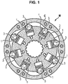
- a radial piston hydraulic machine such as a motor or a pump, comprises a lobed cam opposite which are distributed pistons which are each housed in a respective cylinder.
- the cylinders are generally generally arranged in a star in a cylinder block connected to the shaft of the hydraulic machine.
- the cam is a cam having eccentricity relative to the shaft, or a multilobed cam.
- the pistons each comprise a roller, also called roller, in the form of a cylinder of revolution rotatably mounted in a housing formed at one end of each of said pistons, so that said roller rolls along the lobed cam during the rotation of the piston. cam during engine operation.
- the axis of rotation of the roller is perpendicular to the axis of the cylinder in which the piston slides.
- inserts are mounted between each end of said roller and the cylinder in which said slide piston.
- the present invention aims to propose a new piston architecture for a radial piston hydraulic machine, such as a pump or a motor.
- a piston configured to slide along a cylinder of a radial piston machine, said piston comprising a roller mounted to rotate about a first axis in a housing located at a end of said piston, characterized in that said piston comprises two inserts located on either side of the roller so that each of the inserts form a stop for a translation of the roller along the first axis inside the housing, each of the inserts. comprising a first face bearing on only a portion of the surface of an axial end of the roller, and a second face configured to slide along the cylinder, the roller being movable in translation along the first axis between the two inserts, and the inserts being movable in translation along the first axis inside the housing.
- the invention thus makes it possible to substantially limit the friction created by the rotation of the roller inside the piston housing.
- the first face of the inserts is supported on less than 20% of the surface of the axial end of the roller.
- the inserts each comprise a main body which comprises a cavity in which is inserted a piece projecting from said cavity towards the interior of the housing to bear against the roller.
- the inserts are formed solely of a main body forming both the first face and the second face.
- the support of the first face of each of the inserts is centered around a point whose spacing relative to the first axis is between 0% and 30% of the radius of the roller.
- the first face of the inserts is concave and the ends of the roller are convex, or the first face of the inserts is convex and the ends of the roller are concave.
- the first face of the inserts is flat and the ends of the roller are convex, or the first face of the inserts is convex and the ends of the roller are planar.
- the second face of the inserts comprises a groove or rib configured to cooperate with a rib or a complementary groove located on the cylinder.
- the invention also relates to a radial piston hydraulic machine comprising a piston according to any one of the abovementioned characteristics.
- the invention also relates to a vehicle equipped with a radial piston hydraulic machine of the aforementioned type.
- the piston 1 comprises a cylindrical body 10 and which is adapted to slide in reciprocating movements in a cylinder 2 along a second axis ⁇ .
- the piston 1 is centered around the axis ⁇ .
- the piston 1 comprises a first portion with a first diameter which forms a piston body 1, and a second portion having a second diameter which is larger than the first diameter and which thus forms a piston head.
- the piston is formed of an element having only one diameter and which forms both the piston body and the piston head.
- the piston 1 comprises a directory sealing element according to the second axis ⁇ making it possible to guarantee the seal between the piston 1 and the cylinder 2.
- This sealing element may be formed of a ring or a segment of seal.
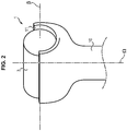
- the piston 1 comprises a roller 3 which is rotatably mounted in a housing 11 of complementary shape to said roller 3 which is formed at one end of the head of said piston 1.
- the roller 3 is a cylinder of revolution which comprises as main axis the first axis ⁇ .
- roller 3 rolls along a cam C lobed M hydraulic machine, thereby causing the rotation of said roller 3 about the first axis ⁇ , which is perpendicular to the second axis ⁇ .
- the roller 3 allows a relative displacement by rolling between the piston 1 and the cam C limiting the friction.
- a bearing 4 whose shape is complementary to the roller 3 is installed at the bottom of the housing 11, so that the roller 3 does not rub against the walls of said housing 11 but against said pad 4.
- the pad 4 is generally made of a copper alloy, or metal coated with synthetic material charged with particles of copper alloy, in order to limit the coefficient of friction between the roller 3 and the pad 4.
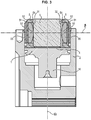
- inserts 5 are arranged on either side of the axial ends 31 and 32 of the roller 3.
- inserts 5 each form an abutment limiting the axial displacement of the roller 3 in a translation axis ⁇ .
- the inserts 5 are interposed between on the one hand the wall of the cavity of the cylinder 2 in which the piston 1 is disposed, and the other ends 31, 32 of the roller 3, and thus realize the axial abutment of the roller 3 respectively d one side and the other of the roller 3.
- the spacing between the inserts 5 is greater than the length of the roller 3, so that the roller 3 is movable in translation between the two stops formed by the inserts 5.
- the roller 3 therefore relies on only one of these two stops, the inserts 5, at a given moment.
- the translational play of the roller 3 must advantageously prevent jamming of the roller 3, even when the hydraulic machine M heats up.
- This game must preferably be greater than or equal to 0.1 mm, preferably 0.2 mm, and may be up to 1 mm.
- the inserts 5 form an abutment alternatively, the insert 5 which is pressed against the cylinder 2 forming a stop, the other insert 5 being slightly spaced from the cylinder 2 because of the slight difference between the diameter of the piston 1 and the cylinder 2.
- the two inserts 5 are in contact against the cylinder 2 simultaneously.
- the inserts 5 can be sufficiently close together to prevent the roller 3 from sliding along the axis ⁇ . This choice can be interesting to obtain a silent hydraulic machine M, or if there is no heating.
- the inserts 5 are advantageously located on either side of the ends of the pad 4, so as to be in contact with the lateral surface of the pad 4.
- the spacing between the inserts 5 is defined by the length of the pad 4.
- the inserts 5 also define the axial location of the pad 4 in the piston, along the first axis ⁇ .
- the inserts 5 may be adapted to cooperate with the housing 11 of the piston 1 so as to limit or completely block the rotation of said inserts 5 along the first axis ⁇ .
- the inserts 5 may comprise a groove which engages in a groove formed inside the housing 11, so as to limit or block the rotation of the inserts 5 along the first axis ⁇ .
- the inserts 5 can also be mounted tight inside the housing 11, thus blocking rotation and translation along the first axis ⁇ .
- Each insert 5 comprises a first face 51 which is intended to bear against the roller 3, and a second face 52 configured to bear against the cylinder 2 and slide along said cylinder 2 during the movements of the piston back and forth 1 inside said cylinder 2.
- Such inserts 5 thus allow a simplified assembly of the piston 1 because they allow on the one hand that the piston 1 is composed of simple elements to manufacture (for example with simple shapes to be machined), and on the other hand they allow to 'soften manufacturing tolerances.
- the inserts 5 can be mounted so as to slide along the first axis ⁇ inside the housing 11. Alternatively, it is however possible to mount the inserts 5 fixedly inside said housing 11.
- the inserts 5 shown on the figure 3 comprise a main body 53 which comprises a cavity 54 opening at the first face 51 of said inserts 5.
- a piece 55 is inserted into the cavity 54 and projects from said cavity 54 so that the support between the inserts 5 and the roller 3 is performed by the piece 55.
- the second face 52 is formed by the main body 53.
- the inserts 5 comprise a main body 53 and a part 55 makes it easier to manufacture the inserts and to reduce the manufacturing cost.
- the main body 53 can be in an inexpensive and easy to form material, such as plastic, because said main body is not in contact with the roller 3.
- the part 55 may in turn be in a material that is adapted for friction against the roller 3.
- the part 55 may for example be of a hardness that is similar to the hardness of the roller 3.
- the part 55 being of a reduced size and having a simple shape, its manufacture is simple and inexpensive.
- the roller 3 is generally made of steel, the piece 55 may be steel, nitrided steel, bronze, or polymer such as for example Vespel®.
- the material of the part 55 may be adapted depending on the material of the roller 3.
- the part 55 may also have undergone a heat treatment and / or chemical to improve its hardness and / or its coefficient of float such as nitriding.
- the part 55 is a part adapted for friction, and can thus be made of copper alloy in order to limit the coefficient of friction between said part 55 and the roller 3.
- the inserts 5 may comprise a groove or a rib directed along the axis ⁇ and located on the second face 52 of said inserts which cooperates with a rib or a rib.
- complementary groove formed in the cylinder 2 so as to form a slide connection of axis ⁇ .
- the complementary rib formed in the cylinder 2 may be formed by an element which is inserted into the radially outer wall of the cylinder block and which projects inside said cylinder. Such a solution is for example described in the document FR2727471 .
- the first face 51 of each insert 5 is configured to bear against only a portion of the surface of the axial ends 31 and 32 of said roller 3. Otherwise, said first face 51 of each insert 5 does not bear against the entire surface of the axial ends 31 and 32 .
- the inserts described in the document FR2651836 abut against the entire surface of the ends of the roller because the face of the inserts bearing against the ends of the roller is a flat circular face and said ends of said roller are flat circular faces of the same diameter as the inserts.
- the first face 51 of the inserts 5 according to the invention is thus configured not to come into contact with the ends 31 and 32 over their entire surface (thus forming for example a point or line support).
- the contact surface between the first face 51 of the inserts 5 and the axial ends 31 and 32 of the roller 3 is less than 20% of the area of said ends 31 and 32. Even more preferably, the contact surface between the first face 51 of the inserts 5 and the axial ends 31 and 32 of the roller 3 is less than 10% of the area of said ends 31 and 32. And even more advantageously, the contact surface between the first face 51 of the inserts 5 and the axial ends 31 and 32 of the roller 3 is less than 5% of the area of said ends 31 and 32.
- the point support between the inserts 5 and the roller 3 is located near the first axis ⁇ , or otherwise on the axis of rotation of the roller 3.
- the fact that the support between the inserts 5 and the roller 3 is as close as possible to the first axis ⁇ is indeed preferable because the radial speed of the roller 3 is lower at the of its axis of rotation.
- the support between each insert 5 and the roller 3 forms a circular zone.
- the support between the first face 51 of the inserts 5 and the axial ends 31 and 32 of the roller 3 is formed in a central zone of the ends 31 and 32, so that the peripheral portion said ends 31 and 32 (radially distant from the first axis ⁇ ) are not in contact with the inserts 5.
- the spacing between the center of the support between the first face 51 of the inserts 5 and the axial ends 31 and 32 of the roller 3 and the first axis ⁇ is less than a maximum radius, for example between 0% and 30% of the radius of the roller 3.
- the support between the first face 51 of the inserts 5 and the axial ends 31 and 32 of the roller 3 is centered on the axis ⁇ , so as to minimize friction.
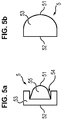
- FIGS 4a, 4b, 4c and 4d illustrate four possible variants of shapes of the first face 51 of the inserts 5 and roller 3 to reduce the surface of the support between said first face 51 and the ends of the roller 3.
- the variants given in these figures are not other forms of course being possible in order to provide one-off support.
- the first face 51 of the inserts 5 has a convex shape, that is to say that it is convex towards the inside of the housing 11 of the piston 1, and on the other hand the ends 31 and 32 of the roller 3 are flat.
- the first face 51 of the inserts 5 is concave, that is to say hollowed towards the outside of the housing 11, and on the other hand the ends 31 and 32 of the roller 3 are convex, it is ie, bulging outward of the housing 11.
- the radius of curvature the concavity of the first face 51 of the inserts 5 is greater than the radius of curvature of the convexity of the ends 31 and 32, so that the first face 51 of the inserts is in contact only on a portion of the ends 31 and 32.
- the difference between the two radii of curvature must be such that the contact surface between the inserts 5 and the ends 31 and 32 of the roller 3 is less than 20% of the area of said axial ends 31 and 32 of the roller 3.
- Such a characteristic can for example, when the radius of curvature of the convex surface is less than 20% of the radius of curvature of the concave surface.
- the first face 51 of the inserts 5 is convex, that is to say convex towards the inside of the housing 11, and on the other hand the ends 31 and 32 of the roller 3 are concave, it is In other words, the radius of curvature of the convexity of the first face 51 is smaller than the radius of curvature of the concavity of the ends 31 and 32 of the roller 3, so as to ensure a punctual support and not surface.
- the variants illustrated in Figures 4c and 4d have the advantage of preventing a radial displacement relative to the first axis ⁇ of the roller 3 in the housing 11, the inserts 5 acting as radial abutments to the roller 3. This thus reduces the necessary depth of the housing 11, and thus d on the one hand to reduce the material required for the manufacture of the piston 1, and secondly to ensure more easily that the end of the piston 1 comprising the housing 11 does not come into contact with the lobed cam during operation of the machine. This furthermore makes it possible to maintain the roller 3 with the piston 1, during the assembly of the hydraulic machine M, or when, due to a lack of pressure in the hydraulic machine M, the piston 1 is retracted and the roller 3 is spaced from the cam C. Indeed, in these variants the inserts 5 grip the roller 3 from the moment when the piston 1 assembled is placed in the cylinder 2.
- the first face 51 of the inserts 5 is convex, that is to say convex towards the interior of the housing 11, and the axial ends 31 and 32 of the roller 3 are also convex, that is, ie bulging outward of the dwelling 11.
- the concavity and / or the convexity of the faces 51 of the inserts 5 and / or the ends 31 and 32 of the roller 3 may be formed by an angle instead of being formed by an arc of a circle, as in the variants illustrated in FIGS. figures 3a-3d .
- the angle difference must be greater than 20 °, preferably greater than 30 °, and still more preferably 40 °.
- inserts 5 having a first angular face 51 with a roller 3 having axial ends 31 and 32 rounded, whether concave or convex.
- the axial ends 31 and 32 may be angular and the first face 51 of the rounded inserts 5, whether concave or convex.
- the inserts 5 can be configured to cooperate with the housing 11 of the piston 1 so as to limit the rotation of the inserts 5 along the first axis ⁇ .
- the shape of the inserts 5 can be adapted so that the rotation of the inserts 5 along the first axis ⁇ is completely blocked, or so that a movement of the inserts 5 along the first axis ⁇ is still possible.
- the position of the inserts 5 in the housing 11 can be determined by the support on the cylinder 2, while there may be a slight angle between the piston 1 and the cylinder 2, which induces a non-perpendicularity between the roller 3 and the inserts 5.
- the position of the inserts 5 in the housing 11 can also be determined by the bearing on the bearing 4, especially in the case of mounting without axial play of the roller 3 between the inserts 5. However, a certain angular tolerance remains.
- the particular shape of the first face 51 of the inserts 5 and the ends 31 and 32 of the roller 3 makes it possible to maintain the limited support between the roller 3 and the inserts 5, preferably located at the level of the first axis ⁇ .
- the angular tolerance of the inserts 5 in the housing 11 of the piston 1 may be between 0 ° and 5 °, and said angular tolerance is preferably 0.5 °.
- the insert 5 comprises a main body 53 in which a cavity 54 is hollowed out at the first face 51.
- a part 55 used to come into contact with the roller 3 is inserted into the cavity 54 and projects from said cavity 54 inwardly of the housing 11 of the piston so that the ends 31 and 32 of the roller 3 abut against said part 55 and not against the main body 53.
- the piece 55 may for example be a cylindrical pin which is inserted into the cavity 54 of the main body 53 and which comes into contact with the roller 3 at one of its circular faces.
- the part 55 can also be a ball which is rotatably mounted in the cavity 54, thus making it possible to improve the rotation of the roller 3.
- the shape of the first face 51 of the insert 5 which abuts against the roller 3 may be chosen by inserting a part 55 which has the desired shape.
- said workpiece 55 can be mounted tightly within said cavity.
- the part 55 can also be overmolded in the body 53, and be shaped to prevent the rotation of said workpiece 55 relative to the body 53, and prevent its tearing out of said body 53.
- the workpiece 55 may comprise for example grooves along of its circumference, a pin, or anti-rotation ribs on the face of the part 55 in plane support on the body 53.
- the piece 55 is made of a copper alloy, such as bronze for example, in order to limit friction with the roller 3.
- the insert 5 is composed solely of its main body 53 which forms both the first face 51 and the second face 52.
- the main body 53 may comprise a pion-shaped cylindrical end projecting towards the inside of the housing 11 and bearing against the roller 3.
- the insert 5 may be of molded plastic material in a material having a molding accuracy, temperature resistance, sufficient hardness.
- a filled thermoplastic such as a polyamide loaded with beads or glass fibers.
- the insert 5 can also be made in the mass in a material capable of friction on steel, such as a cuprous material, for example a bronze. In this case, it can be machined or molded.
- the second face 52 of the inserts 5 is of complementary shape to the wall of the cylinder 2 against which said second face 52 comes to rest.
- the second face 52 is preferably a surface forming a portion of a cylinder whose diameter is equal to the diameter of the cylinder 2.
- the second face 52 of the inserts 5 may be formed by an additional piece which is fixed on said inserts 5, which is attached or overmolded, and which can for example be used to limit the friction between the inserts 5 and the cylinder 2.
- additional piece may have a surface forming a portion of a cylinder whose diameter is equal to the diameter of the cylinder 2 in which the additional piece slides.
- the additional piece may be adapted to not be rotated about the first axis ⁇ .
- the additional piece can thus comprise elements projecting from said additional piece and cooperating with elements of complementary shape dug in the insert 5 in order to block the rotation along the first axis ⁇ .
- Elements projecting from the additional part may also cooperate with elements of complementary shape dug in the cylinder 2, so as to prevent rotation of the additional part along the first axis ⁇ with respect to the cylinder 2.
- These projecting elements may for example for example, ribs formed on the additional piece.
- each of the axial ends 31 and 32 of the roller 3 comprises a ball rotatably mounted in said roller 3. These balls, which are centered on the first axis ⁇ , come into contact with the first face 51 of the inserts 5, and allow to limit the friction.
- each of the axial ends 31 and 32 of the roller 3 comprises a cylindrical end in the form of a pin making a contact on a part of the surface of the insert (5).
Landscapes
- Engineering & Computer Science (AREA)
- Mechanical Engineering (AREA)
- General Engineering & Computer Science (AREA)
- Chemical & Material Sciences (AREA)
- Combustion & Propulsion (AREA)
- Reciprocating Pumps (AREA)
Applications Claiming Priority (1)
| Application Number | Priority Date | Filing Date | Title |
|---|---|---|---|
| FR1655632A FR3052820B1 (fr) | 2016-06-16 | 2016-06-16 | Piston pour une machine hydraulique a pistons radiaux a frottements limites |
Publications (2)
| Publication Number | Publication Date |
|---|---|
| EP3258100A1 true EP3258100A1 (de) | 2017-12-20 |
| EP3258100B1 EP3258100B1 (de) | 2019-01-23 |
Family
ID=56611454
Family Applications (1)
| Application Number | Title | Priority Date | Filing Date |
|---|---|---|---|
| EP17176083.8A Active EP3258100B1 (de) | 2016-06-16 | 2017-06-14 | Kolben für eine hydraulische maschine mit radialen kolben mit begrenzter reibung |
Country Status (2)
| Country | Link |
|---|---|
| EP (1) | EP3258100B1 (de) |
| FR (1) | FR3052820B1 (de) |
Citations (5)
| Publication number | Priority date | Publication date | Assignee | Title |
|---|---|---|---|---|
| FR2651836A1 (fr) * | 1989-09-14 | 1991-03-15 | Poclain Hydraulics Sa | Mecanisme, moteur ou pompe, a pistons supportant des rouleaux d'appui desdits pistons sur une came. |
| FR2727471A1 (fr) * | 1994-11-30 | 1996-05-31 | Poclain Hydraulics Sa | Mecanisme, moteur ou pompe, a pistons munis de rouleaux d'appui sur une came |
| EP1062426B1 (de) * | 1998-03-10 | 2002-10-02 | Mannesmann Rexroth AG | Radialkolbenmotor mit rollenführung |
| DE10205493A1 (de) * | 2002-02-09 | 2003-08-28 | Bosch Gmbh Robert | Radialkolbenpumpe mit integrierter Niederdruckpumpe |
| DE102013218260A1 (de) * | 2013-09-12 | 2015-03-12 | Continental Automotive Gmbh | Rollenstößel |
-
2016
- 2016-06-16 FR FR1655632A patent/FR3052820B1/fr not_active Expired - Fee Related
-
2017
- 2017-06-14 EP EP17176083.8A patent/EP3258100B1/de active Active
Patent Citations (5)
| Publication number | Priority date | Publication date | Assignee | Title |
|---|---|---|---|---|
| FR2651836A1 (fr) * | 1989-09-14 | 1991-03-15 | Poclain Hydraulics Sa | Mecanisme, moteur ou pompe, a pistons supportant des rouleaux d'appui desdits pistons sur une came. |
| FR2727471A1 (fr) * | 1994-11-30 | 1996-05-31 | Poclain Hydraulics Sa | Mecanisme, moteur ou pompe, a pistons munis de rouleaux d'appui sur une came |
| EP1062426B1 (de) * | 1998-03-10 | 2002-10-02 | Mannesmann Rexroth AG | Radialkolbenmotor mit rollenführung |
| DE10205493A1 (de) * | 2002-02-09 | 2003-08-28 | Bosch Gmbh Robert | Radialkolbenpumpe mit integrierter Niederdruckpumpe |
| DE102013218260A1 (de) * | 2013-09-12 | 2015-03-12 | Continental Automotive Gmbh | Rollenstößel |
Also Published As
| Publication number | Publication date |
|---|---|
| FR3052820A1 (fr) | 2017-12-22 |
| FR3052820B1 (fr) | 2019-07-19 |
| EP3258100B1 (de) | 2019-01-23 |
Similar Documents
| Publication | Publication Date | Title |
|---|---|---|
| FR2850130A1 (fr) | Dispositif pour retenir un flasque annulaire contre une face radiale d'un disque | |
| EP3388252B1 (de) | Spannvorrichtung, insbesondere zum festziehen eines sattels auf einem fahrrad | |
| FR3015597A1 (fr) | Dispositif de rouleau suiveur de came | |
| EP2904290B1 (de) | Torsionsdämpfende vorrichtung mit federn und kippbaren sitzen | |
| WO1999045287A1 (fr) | Organe de transmission mecanique et son application a un joint mecanique homocinetique | |
| FR2991722A3 (fr) | Papillon des gaz pour un moteur a combustion interne pourvu d'un siege de soupape en metal surmoule a l'interieur d'un carter de soupape en matiere plastique | |
| EP3472465B1 (de) | Walzenkolben für eine hydraulische maschine mit integriertem zentrierelement zur begrenzung der reibung mit einer walze | |
| EP3258100B1 (de) | Kolben für eine hydraulische maschine mit radialen kolben mit begrenzter reibung | |
| EP1679445A1 (de) | Führungselement für ein bewegbares Teil | |
| FR3030665A1 (fr) | Piston a galet monobloc et procede associe | |
| FR3013784A1 (fr) | Moyeu de synchronisation pour une unite de synchronisation d'une boite de vitesses et unite de synchronisation presentant un tel moyeu de synchronisation | |
| FR2869081A1 (fr) | Palier a roulement | |
| EP3565983B1 (de) | Synchronisierte freilaufrolle | |
| FR3063325A1 (fr) | Attelage articule pour dispositif d'etancheite pour piston | |
| EP2364408A1 (de) | Linearbetätigungsglied | |
| WO2020201132A1 (fr) | Fabrication d'un réservoir à gaz sous haute pression | |
| EP2811189A1 (de) | Segmentiertes Gehäuse für Rolleinheit | |
| WO2017186905A1 (fr) | Machine hydraulique debrayable et vehicule equipe d'une telle machine | |
| EP4584491A1 (de) | Kraftstoffpumpe für direkteinspritzung für brennkraftmaschinen mit sicherungsscheibe | |
| EP3069044B1 (de) | Träger für eine dämpfungsvorrichtung für ein fahrzeuggetriebesystem | |
| FR2770603A1 (fr) | Reacteur de convertisseur hydrodynamique de couple | |
| FR3000772A1 (fr) | Cage pour unite de roulement, et unite de roulement munie d'une telle cage. | |
| FR3133800A1 (fr) | Mécanisme d'articulation et siège de véhicule comportant un tel mécanisme. | |
| FR2775455A1 (fr) | Mecanismes d'essuie-glace de vehicule automobile comportant un palier de support d'un arbre, palier pour un tel mecanisme et procede de realisation d'un mecanisme d'essuie-glace | |
| FR2900703A1 (fr) | Dispositif de liaison entre un vilebrequin et des bielles |
Legal Events
| Date | Code | Title | Description |
|---|---|---|---|
| PUAI | Public reference made under article 153(3) epc to a published international application that has entered the european phase |
Free format text: ORIGINAL CODE: 0009012 |
|
| STAA | Information on the status of an ep patent application or granted ep patent |
Free format text: STATUS: REQUEST FOR EXAMINATION WAS MADE |
|
| 17P | Request for examination filed |
Effective date: 20170614 |
|
| AK | Designated contracting states |
Kind code of ref document: A1 Designated state(s): AL AT BE BG CH CY CZ DE DK EE ES FI FR GB GR HR HU IE IS IT LI LT LU LV MC MK MT NL NO PL PT RO RS SE SI SK SM TR |
|
| AX | Request for extension of the european patent |
Extension state: BA ME |
|
| GRAP | Despatch of communication of intention to grant a patent |
Free format text: ORIGINAL CODE: EPIDOSNIGR1 |
|
| STAA | Information on the status of an ep patent application or granted ep patent |
Free format text: STATUS: GRANT OF PATENT IS INTENDED |
|
| RIC1 | Information provided on ipc code assigned before grant |
Ipc: F03C 1/30 20060101ALI20180711BHEP Ipc: F04B 1/04 20060101AFI20180711BHEP Ipc: F03C 1/04 20060101ALI20180711BHEP |
|
| INTG | Intention to grant announced |
Effective date: 20180810 |
|
| GRAS | Grant fee paid |
Free format text: ORIGINAL CODE: EPIDOSNIGR3 |
|
| GRAA | (expected) grant |
Free format text: ORIGINAL CODE: 0009210 |
|
| STAA | Information on the status of an ep patent application or granted ep patent |
Free format text: STATUS: THE PATENT HAS BEEN GRANTED |
|
| AK | Designated contracting states |
Kind code of ref document: B1 Designated state(s): AL AT BE BG CH CY CZ DE DK EE ES FI FR GB GR HR HU IE IS IT LI LT LU LV MC MK MT NL NO PL PT RO RS SE SI SK SM TR |
|
| REG | Reference to a national code |
Ref country code: GB Ref legal event code: FG4D Free format text: NOT ENGLISH |
|
| REG | Reference to a national code |
Ref country code: CH Ref legal event code: EP |
|
| REG | Reference to a national code |
Ref country code: AT Ref legal event code: REF Ref document number: 1091664 Country of ref document: AT Kind code of ref document: T Effective date: 20190215 |
|
| REG | Reference to a national code |
Ref country code: IE Ref legal event code: FG4D Free format text: LANGUAGE OF EP DOCUMENT: FRENCH |
|
| REG | Reference to a national code |
Ref country code: DE Ref legal event code: R096 Ref document number: 602017001887 Country of ref document: DE |
|
| REG | Reference to a national code |
Ref country code: NL Ref legal event code: MP Effective date: 20190123 |
|
| PG25 | Lapsed in a contracting state [announced via postgrant information from national office to epo] |
Ref country code: NL Free format text: LAPSE BECAUSE OF FAILURE TO SUBMIT A TRANSLATION OF THE DESCRIPTION OR TO PAY THE FEE WITHIN THE PRESCRIBED TIME-LIMIT Effective date: 20190123 |
|
| PG25 | Lapsed in a contracting state [announced via postgrant information from national office to epo] |
Ref country code: SE Free format text: LAPSE BECAUSE OF FAILURE TO SUBMIT A TRANSLATION OF THE DESCRIPTION OR TO PAY THE FEE WITHIN THE PRESCRIBED TIME-LIMIT Effective date: 20190123 Ref country code: LT Free format text: LAPSE BECAUSE OF FAILURE TO SUBMIT A TRANSLATION OF THE DESCRIPTION OR TO PAY THE FEE WITHIN THE PRESCRIBED TIME-LIMIT Effective date: 20190123 Ref country code: ES Free format text: LAPSE BECAUSE OF FAILURE TO SUBMIT A TRANSLATION OF THE DESCRIPTION OR TO PAY THE FEE WITHIN THE PRESCRIBED TIME-LIMIT Effective date: 20190123 Ref country code: PL Free format text: LAPSE BECAUSE OF FAILURE TO SUBMIT A TRANSLATION OF THE DESCRIPTION OR TO PAY THE FEE WITHIN THE PRESCRIBED TIME-LIMIT Effective date: 20190123 Ref country code: PT Free format text: LAPSE BECAUSE OF FAILURE TO SUBMIT A TRANSLATION OF THE DESCRIPTION OR TO PAY THE FEE WITHIN THE PRESCRIBED TIME-LIMIT Effective date: 20190523 Ref country code: NO Free format text: LAPSE BECAUSE OF FAILURE TO SUBMIT A TRANSLATION OF THE DESCRIPTION OR TO PAY THE FEE WITHIN THE PRESCRIBED TIME-LIMIT Effective date: 20190423 Ref country code: FI Free format text: LAPSE BECAUSE OF FAILURE TO SUBMIT A TRANSLATION OF THE DESCRIPTION OR TO PAY THE FEE WITHIN THE PRESCRIBED TIME-LIMIT Effective date: 20190123 |
|
| REG | Reference to a national code |
Ref country code: AT Ref legal event code: MK05 Ref document number: 1091664 Country of ref document: AT Kind code of ref document: T Effective date: 20190123 |
|
| PG25 | Lapsed in a contracting state [announced via postgrant information from national office to epo] |
Ref country code: IS Free format text: LAPSE BECAUSE OF FAILURE TO SUBMIT A TRANSLATION OF THE DESCRIPTION OR TO PAY THE FEE WITHIN THE PRESCRIBED TIME-LIMIT Effective date: 20190523 Ref country code: BG Free format text: LAPSE BECAUSE OF FAILURE TO SUBMIT A TRANSLATION OF THE DESCRIPTION OR TO PAY THE FEE WITHIN THE PRESCRIBED TIME-LIMIT Effective date: 20190423 Ref country code: RS Free format text: LAPSE BECAUSE OF FAILURE TO SUBMIT A TRANSLATION OF THE DESCRIPTION OR TO PAY THE FEE WITHIN THE PRESCRIBED TIME-LIMIT Effective date: 20190123 Ref country code: HR Free format text: LAPSE BECAUSE OF FAILURE TO SUBMIT A TRANSLATION OF THE DESCRIPTION OR TO PAY THE FEE WITHIN THE PRESCRIBED TIME-LIMIT Effective date: 20190123 Ref country code: GR Free format text: LAPSE BECAUSE OF FAILURE TO SUBMIT A TRANSLATION OF THE DESCRIPTION OR TO PAY THE FEE WITHIN THE PRESCRIBED TIME-LIMIT Effective date: 20190424 Ref country code: LV Free format text: LAPSE BECAUSE OF FAILURE TO SUBMIT A TRANSLATION OF THE DESCRIPTION OR TO PAY THE FEE WITHIN THE PRESCRIBED TIME-LIMIT Effective date: 20190123 |
|
| REG | Reference to a national code |
Ref country code: DE Ref legal event code: R097 Ref document number: 602017001887 Country of ref document: DE |
|
| PG25 | Lapsed in a contracting state [announced via postgrant information from national office to epo] |
Ref country code: CZ Free format text: LAPSE BECAUSE OF FAILURE TO SUBMIT A TRANSLATION OF THE DESCRIPTION OR TO PAY THE FEE WITHIN THE PRESCRIBED TIME-LIMIT Effective date: 20190123 Ref country code: IT Free format text: LAPSE BECAUSE OF FAILURE TO SUBMIT A TRANSLATION OF THE DESCRIPTION OR TO PAY THE FEE WITHIN THE PRESCRIBED TIME-LIMIT Effective date: 20190123 Ref country code: RO Free format text: LAPSE BECAUSE OF FAILURE TO SUBMIT A TRANSLATION OF THE DESCRIPTION OR TO PAY THE FEE WITHIN THE PRESCRIBED TIME-LIMIT Effective date: 20190123 Ref country code: SK Free format text: LAPSE BECAUSE OF FAILURE TO SUBMIT A TRANSLATION OF THE DESCRIPTION OR TO PAY THE FEE WITHIN THE PRESCRIBED TIME-LIMIT Effective date: 20190123 Ref country code: AL Free format text: LAPSE BECAUSE OF FAILURE TO SUBMIT A TRANSLATION OF THE DESCRIPTION OR TO PAY THE FEE WITHIN THE PRESCRIBED TIME-LIMIT Effective date: 20190123 Ref country code: DK Free format text: LAPSE BECAUSE OF FAILURE TO SUBMIT A TRANSLATION OF THE DESCRIPTION OR TO PAY THE FEE WITHIN THE PRESCRIBED TIME-LIMIT Effective date: 20190123 Ref country code: EE Free format text: LAPSE BECAUSE OF FAILURE TO SUBMIT A TRANSLATION OF THE DESCRIPTION OR TO PAY THE FEE WITHIN THE PRESCRIBED TIME-LIMIT Effective date: 20190123 |
|
| PG25 | Lapsed in a contracting state [announced via postgrant information from national office to epo] |
Ref country code: SM Free format text: LAPSE BECAUSE OF FAILURE TO SUBMIT A TRANSLATION OF THE DESCRIPTION OR TO PAY THE FEE WITHIN THE PRESCRIBED TIME-LIMIT Effective date: 20190123 |
|
| PLBE | No opposition filed within time limit |
Free format text: ORIGINAL CODE: 0009261 |
|
| STAA | Information on the status of an ep patent application or granted ep patent |
Free format text: STATUS: NO OPPOSITION FILED WITHIN TIME LIMIT |
|
| PG25 | Lapsed in a contracting state [announced via postgrant information from national office to epo] |
Ref country code: AT Free format text: LAPSE BECAUSE OF FAILURE TO SUBMIT A TRANSLATION OF THE DESCRIPTION OR TO PAY THE FEE WITHIN THE PRESCRIBED TIME-LIMIT Effective date: 20190123 |
|
| 26N | No opposition filed |
Effective date: 20191024 |
|
| REG | Reference to a national code |
Ref country code: DE Ref legal event code: R119 Ref document number: 602017001887 Country of ref document: DE |
|
| PG25 | Lapsed in a contracting state [announced via postgrant information from national office to epo] |
Ref country code: MC Free format text: LAPSE BECAUSE OF FAILURE TO SUBMIT A TRANSLATION OF THE DESCRIPTION OR TO PAY THE FEE WITHIN THE PRESCRIBED TIME-LIMIT Effective date: 20190123 |
|
| PG25 | Lapsed in a contracting state [announced via postgrant information from national office to epo] |
Ref country code: SI Free format text: LAPSE BECAUSE OF FAILURE TO SUBMIT A TRANSLATION OF THE DESCRIPTION OR TO PAY THE FEE WITHIN THE PRESCRIBED TIME-LIMIT Effective date: 20190123 |
|
| REG | Reference to a national code |
Ref country code: BE Ref legal event code: MM Effective date: 20190630 |
|
| PG25 | Lapsed in a contracting state [announced via postgrant information from national office to epo] |
Ref country code: TR Free format text: LAPSE BECAUSE OF FAILURE TO SUBMIT A TRANSLATION OF THE DESCRIPTION OR TO PAY THE FEE WITHIN THE PRESCRIBED TIME-LIMIT Effective date: 20190123 |
|
| PG25 | Lapsed in a contracting state [announced via postgrant information from national office to epo] |
Ref country code: IE Free format text: LAPSE BECAUSE OF NON-PAYMENT OF DUE FEES Effective date: 20190614 Ref country code: DE Free format text: LAPSE BECAUSE OF NON-PAYMENT OF DUE FEES Effective date: 20200101 |
|
| PG25 | Lapsed in a contracting state [announced via postgrant information from national office to epo] |
Ref country code: BE Free format text: LAPSE BECAUSE OF NON-PAYMENT OF DUE FEES Effective date: 20190630 Ref country code: LU Free format text: LAPSE BECAUSE OF NON-PAYMENT OF DUE FEES Effective date: 20190614 |
|
| REG | Reference to a national code |
Ref country code: CH Ref legal event code: PL |
|
| PG25 | Lapsed in a contracting state [announced via postgrant information from national office to epo] |
Ref country code: LI Free format text: LAPSE BECAUSE OF NON-PAYMENT OF DUE FEES Effective date: 20200630 Ref country code: CH Free format text: LAPSE BECAUSE OF NON-PAYMENT OF DUE FEES Effective date: 20200630 |
|
| PG25 | Lapsed in a contracting state [announced via postgrant information from national office to epo] |
Ref country code: CY Free format text: LAPSE BECAUSE OF FAILURE TO SUBMIT A TRANSLATION OF THE DESCRIPTION OR TO PAY THE FEE WITHIN THE PRESCRIBED TIME-LIMIT Effective date: 20190123 |
|
| PG25 | Lapsed in a contracting state [announced via postgrant information from national office to epo] |
Ref country code: HU Free format text: LAPSE BECAUSE OF FAILURE TO SUBMIT A TRANSLATION OF THE DESCRIPTION OR TO PAY THE FEE WITHIN THE PRESCRIBED TIME-LIMIT; INVALID AB INITIO Effective date: 20170614 Ref country code: MT Free format text: LAPSE BECAUSE OF FAILURE TO SUBMIT A TRANSLATION OF THE DESCRIPTION OR TO PAY THE FEE WITHIN THE PRESCRIBED TIME-LIMIT Effective date: 20190123 |
|
| PG25 | Lapsed in a contracting state [announced via postgrant information from national office to epo] |
Ref country code: MK Free format text: LAPSE BECAUSE OF FAILURE TO SUBMIT A TRANSLATION OF THE DESCRIPTION OR TO PAY THE FEE WITHIN THE PRESCRIBED TIME-LIMIT Effective date: 20190123 |
|
| P01 | Opt-out of the competence of the unified patent court (upc) registered |
Effective date: 20230513 |
|
| PGFP | Annual fee paid to national office [announced via postgrant information from national office to epo] |
Ref country code: GB Payment date: 20230620 Year of fee payment: 7 |
|
| GBPC | Gb: european patent ceased through non-payment of renewal fee |
Effective date: 20240614 |
|
| PG25 | Lapsed in a contracting state [announced via postgrant information from national office to epo] |
Ref country code: GB Free format text: LAPSE BECAUSE OF NON-PAYMENT OF DUE FEES Effective date: 20240614 |
|
| PGFP | Annual fee paid to national office [announced via postgrant information from national office to epo] |
Ref country code: FR Payment date: 20250513 Year of fee payment: 9 |