EP3258183A1 - Procédé et unité de commande destinés à la détection de défaillances dans un système de chauffage et/ou dans un climatiseur et système de chauffage et/ou climatiseur - Google Patents
Procédé et unité de commande destinés à la détection de défaillances dans un système de chauffage et/ou dans un climatiseur et système de chauffage et/ou climatiseur Download PDFInfo
- Publication number
- EP3258183A1 EP3258183A1 EP17175406.2A EP17175406A EP3258183A1 EP 3258183 A1 EP3258183 A1 EP 3258183A1 EP 17175406 A EP17175406 A EP 17175406A EP 3258183 A1 EP3258183 A1 EP 3258183A1
- Authority
- EP
- European Patent Office
- Prior art keywords
- control unit
- air conditioning
- heating system
- conditioning system
- microphone
- Prior art date
- Legal status (The legal status is an assumption and is not a legal conclusion. Google has not performed a legal analysis and makes no representation as to the accuracy of the status listed.)
- Granted
Links
Images



Classifications
-
- B—PERFORMING OPERATIONS; TRANSPORTING
- B60—VEHICLES IN GENERAL
- B60H—ARRANGEMENTS OF HEATING, COOLING, VENTILATING OR OTHER AIR-TREATING DEVICES SPECIALLY ADAPTED FOR PASSENGER OR GOODS SPACES OF VEHICLES
- B60H1/00—Heating, cooling or ventilating devices
- B60H1/00642—Control systems or circuits; Control members or indication devices for heating, cooling or ventilating devices
- B60H1/00735—Control systems or circuits characterised by their input, i.e. by the detection, measurement or calculation of particular conditions, e.g. signal treatment, dynamic models
- B60H1/00757—Control systems or circuits characterised by their input, i.e. by the detection, measurement or calculation of particular conditions, e.g. signal treatment, dynamic models by the input of sound, e.g. by using a voice synthesizer
-
- B—PERFORMING OPERATIONS; TRANSPORTING
- B60—VEHICLES IN GENERAL
- B60H—ARRANGEMENTS OF HEATING, COOLING, VENTILATING OR OTHER AIR-TREATING DEVICES SPECIALLY ADAPTED FOR PASSENGER OR GOODS SPACES OF VEHICLES
- B60H1/00—Heating, cooling or ventilating devices
- B60H1/00642—Control systems or circuits; Control members or indication devices for heating, cooling or ventilating devices
- B60H1/00978—Control systems or circuits characterised by failure of detection or safety means; Diagnostic methods
-
- F—MECHANICAL ENGINEERING; LIGHTING; HEATING; WEAPONS; BLASTING
- F24—HEATING; RANGES; VENTILATING
- F24F—AIR-CONDITIONING; AIR-HUMIDIFICATION; VENTILATION; USE OF AIR CURRENTS FOR SCREENING
- F24F11/00—Control or safety arrangements
- F24F11/30—Control or safety arrangements for purposes related to the operation of the system, e.g. for safety or monitoring
-
- B—PERFORMING OPERATIONS; TRANSPORTING
- B60—VEHICLES IN GENERAL
- B60H—ARRANGEMENTS OF HEATING, COOLING, VENTILATING OR OTHER AIR-TREATING DEVICES SPECIALLY ADAPTED FOR PASSENGER OR GOODS SPACES OF VEHICLES
- B60H1/00—Heating, cooling or ventilating devices
- B60H1/00642—Control systems or circuits; Control members or indication devices for heating, cooling or ventilating devices
- B60H1/00735—Control systems or circuits characterised by their input, i.e. by the detection, measurement or calculation of particular conditions, e.g. signal treatment, dynamic models
- B60H1/00764—Control systems or circuits characterised by their input, i.e. by the detection, measurement or calculation of particular conditions, e.g. signal treatment, dynamic models the input being a vehicle driving condition, e.g. speed
-
- F—MECHANICAL ENGINEERING; LIGHTING; HEATING; WEAPONS; BLASTING
- F24—HEATING; RANGES; VENTILATING
- F24F—AIR-CONDITIONING; AIR-HUMIDIFICATION; VENTILATION; USE OF AIR CURRENTS FOR SCREENING
- F24F2110/00—Control inputs relating to air properties
-
- F—MECHANICAL ENGINEERING; LIGHTING; HEATING; WEAPONS; BLASTING
- F24—HEATING; RANGES; VENTILATING
- F24F—AIR-CONDITIONING; AIR-HUMIDIFICATION; VENTILATION; USE OF AIR CURRENTS FOR SCREENING
- F24F2130/00—Control inputs relating to environmental factors not covered by group F24F2110/00
- F24F2130/40—Noise
Definitions
- the invention relates to a method for detecting false states in a heating system and / or in an air conditioning system, in particular in a HVAC system, with a control unit having at least one acceleration sensor and / or at least one microphone.
- the invention also relates to a control unit which is designed to carry out the method according to the invention and to a heating system and / or an air conditioning system with the control unit according to the invention.
- a state of the heating system and / or the air conditioning system is meant by "faulty state" in which the operation is not possible in the intended frame.
- defects and malfunctions include defects and malfunctions as well as a non-optimal operation.
- defects and malfunctions are completely or partially non-functioning pumps and / or valves, a disturbing noise, such as a whistle, or a loss of water during a pipe burst.
- a non-optimal operation are over or under load of the heating system and / or the air conditioning or a non-optimal combustion in the combustion chamber of the heating system, for example by incorrectly set operating parameters.
- heating system is at least one device for generating heat energy, in particular a heater or heating burner, in particular for use in a building heating and / or hot water production, preferably by to understand the burning of a gaseous or liquid fuel.
- a heating system may also include a plurality of such devices as well as other supporting devices, such as hot water or fuel storage.
- Air conditioning means at least one device for ventilation and / or ventilation and / or ensuring air circulation and / or air quality and / or a device for cooling and / or moisture control in a building.
- a heating system can be used in particular together with an air conditioner.
- a system comprising a heating system and an air conditioner is also referred to as a "Heating-Ventilation-Air-Conditioning System” or HVAC system.
- determining a value is the direct measurement of the value, such as by a corresponding sensor, the receiving and / or processing of information that allow direct or indirect conclusions about the value, as well as a combination of a measurement process with the reception and / or to understand the processing of information.
- the method for detecting faulty states has an additional step in which at least one fault message is output, if a faulty state has been detected, this makes it possible to detect the faulty state and if necessary initiate countermeasures. For example, an inspection can be requested
- At least one correction signal based on the at least one error variable is determined, if a fault condition has been established, countermeasures can be initiated automatically. For example, the heating system and / or the air conditioning system can be shut down to avoid major damage.
- correction signal means at least one signal for activating and / or adjusting the operation of at least one component of the heating system and / or the air conditioning system.
- the correction signal may be a control signal to a fan which changes the fan speed.
- operating parameters based on the at least one error variable, are stored in the control unit in a memory, this allows the targeted control of the heating system and / or the air conditioning system to counteract the fault condition. Particularly in the case of a repeated, preferably periodic execution of the method according to the invention, this permits the iterative correction of a false condition. In this way, the operation of the heating system and / or the air conditioning in a control loop can be optimized. This ensures optimum operation even under varying internal and external conditions, especially during wear processes and changing environmental conditions.
- operating parameters are understood to mean parameters which are used by the control of the heating system and / or the air conditioning system for regulating and monitoring processes taking place in the heating system and / or in the air conditioning system.
- operating parameters are the blower speed or the blower speed characteristic or a flame ionization characteristic.
- the at least one error variable is derived from a measure of the deviation from the at least one sensor signal from an associated desired signal specification, this makes it possible to set the method to specific events triggering the fault condition.
- typical signal behavior can be defined for errors and / or in optimal operation. These typical signal behaviors can be used to detect false states.
- An example of this is a threshold for a microphone signal and its temporal evolution to ensure that the noise level is not too great.
- Another example is a frequency analysis from an accelerometer attached to a pump to determine if the pump is running smoothly and / or in the correct direction of rotation and / or at the right times.
- control unit for a heating system and / or an air conditioning system which is configured to carry out the method according to the invention, has the advantage that in addition to defects and disturbances, a non-optimal operation of the heating system and / or the air conditioning system can be detected. In this way, the efficiency and durability of the heating system and / or the air conditioning is ensured.
- the method can be used to detect fault conditions in different heating systems and / or air conditioning systems.
- the mobile control unit or the mobile parts of the control unit can form a compact functional unit for detecting fault conditions, which can be used simply and easily in inspections of the heating system and / or air conditioning systems.
- the mobile control unit or its mobile parts can detect fault conditions in separate, spatially separated components of a heating system and / or an air conditioning system.
- the sensitive parts of the control unit are thus protected by the thermal and mechanical loads occurring in a heating system.
- control unit has at least one communication connection, preferably a wireless communication connection, between the parts of the control unit, preferably between the mobile and non-mobile parts of the control unit, this allows a particularly simple and secure procedure for the method for detecting false states.
- the operational safety is increased because errors are avoided by a wrong or missing communication connection.
- the at least one sensor signal originates from sensors permanently installed in the heating system and / or in the air conditioning system, to which a communication connection with the mobile control unit has to be established.
- a heating system and / or an air conditioning system with a control unit according to the invention has or have the advantage that disturbances in different operating states of the heating system and / or the air conditioning system are detected. This is not always possible in the prior art as part of an inspection, for example, when faults occur only under certain operating conditions, which are usually not examined during an inspection for reasons of time, or under certain external conditions that are not present during the inspection ,
- the heating system according to the invention and / or the air conditioning system according to the invention has a receptacle provided for the control unit or for parts of the control unit, this allows a particularly problem-free use of a mobile control unit or of the mobile parts of a control unit, for example as part of an inspection.
- a simple upgrade or expansion of the heating system and / or the air conditioning by retrofitting with the control unit or parts of the control unit is possible.
- the heating system and / or the air conditioning system at least one pump, a fan, a heating cell, a housing, a valve, a conduit or a Control unit and has at least one of these components at least one acceleration sensor and / or a microphone, it has the advantage that the at least one acceleration sensor and / or a microphone having component is monitored particularly reliable. If a fault condition occurs, the sensor signal is uniquely assigned to the component. This allows a particularly targeted and clear evaluation of the fault condition.
- a computer program comprising commands which, when a program is executed by a computer, in particular by a mobile computing unit, causes it to carry out at least one step of the method according to the present invention, has the advantage that the method is carried out partly in particular on decentralized computers can, for example, on a cloud or on a smartphone. This increases user comfort and allows, if necessary, a particularly thorough and comprehensive data analysis, which would not be possible on a local control unit of the heating system to the extent, for example.
- FIG. 1 is the inventive method 10 for detecting fault conditions in a heating system 12 (see FIG. 5 ) and / or an air conditioning system with a control unit 14 having an acceleration sensor 16 and a microphone 18.
- a sensor signal 22 is received by the acceleration sensor 16 and the microphone 18 in a step 20, and in a step 24 an error variable 26 is determined by the control unit 14 as a function of the sensor signal 22.
- the error variable 26 is determined with an error function which assigns an error variable 26 to the sensor signal 22.
- the error variable 26 assigned to the sensor signal 22 of the microphone 18 is proportional to the maximum sound level occurring over a defined measuring period.
- the the Error signal 26 associated with sensor signal 22 of acceleration sensor 16 is proportional to the quadratic acceleration value averaged over the measurement period. If the error variable 26 exceeds an error threshold value 28, a false state is determined in a step 30.
- the error threshold value 28 is determined empirically and is stored in a memory 42.
- step 30 If a false state is detected in step 30, the method 10 is continued via the path A (see FIG. 1 ). If no false state is detected, the method 10 is terminated via the path B. If method 10 continues through path A, steps 32 and 34 are performed. In step 32, an error message 33 is output on a display unit 62. In the exemplary embodiment, in the context of the error message 33, besides the error variable 26, the sensor determining the error variable 26 and the error time, the contact information for a service partner authorized for troubleshooting is also displayed.
- a correction signal 36 is sent to the heating system 12 by the control unit 14. Step 34 is executed if the error variable 26 assigned to the acceleration sensor 16 exceeds the associated error threshold value 28.
- the correction signal 36 is a shutdown signal to all components of the heating system 12. The heating system 12 is shut down to prevent damage caused by the occurring too strong accelerations.
- FIG. 2 shows an alternative embodiment of the method 10.
- a step 38 is executed.
- operating parameters 40 are stored in a memory 42 of the control unit 14 based on the error variable 26.
- the error variable 26 is a fan 44 (see FIG. 8 ) with a microphone 18.
- the frequency spectrum of the sensor signal 22 of the microphone 18 is examined in step 24 by the control unit 14 with a Fourier analysis. In this way it can be determined whether the fan 44 is running in the correct speed range. It can also be detected possible bearing damage or imbalances.
- the measure of an error variable 26 is defined by the deviation of the frequency spectrum of the sensor signal 22 of the microphone 18 from the frequency spectrum of a desired signal specification 48, wherein unwanted resonance frequencies of the heating system 12 are particularly heavily weighted.
- the fault threshold value 28 for the sensor signal 22 assigned to the blower 44 describes a still sufficiently good operation of the blower 44 and depends on the operating mode of the heating system 12, for example on the requested power.
- step 30 in FIG. 2
- the method 10 is continued via the path B.
- step 38 is executed.
- 26 dependent operating parameters 40 are stored in the control unit 14 of the error size.
- the operating parameters 40 describe the fan speed characteristic.
- the fan speed curve describes the relationship between the required fan speed and the required drive voltage.
- the blower 44 is controlled so that the blower speed, if necessary, is changed to an optimum blower speed.
- the repeated execution of the method 10 represents a control loop.
- step 30 (in FIG. 2 ) is detected, the method 10 is continued over the path A.
- steps 38 and 32 are executed.
- an error message 33 an inspection requested.
- more than one sensor signal 22 is combined into an error variable 26 in step 24.
- a plurality of acceleration sensors 16 and / or microphones 18 may be attached to one component.
- acceleration sensors 16 and / or microphones 18 may be associated with different components of a HVAC system 12 and combined into an error variable 26.
- a total noise load can be assessed or fault conditions can be detected in which more than one component is involved.
- a restless, hakeliges switching behavior of a valve 52 (see FIG. 8 ) to unwanted vibrations of a line 50 see FIG. 8
- an error variable 26 is determined in step 24, which is inversely proportional to the sensor signal 22.
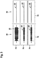
- FIG. 3 schematically shows a time course of the sensor signal 22 of an acceleration sensor 16 to the pump 54.
- the ordinate axes 74, 76 and 78 respectively depict the x, y and z components of the sensor signal 22 that fluctuate about zero with respect to a Cartesian coordinate system.
- state 80 the sensor signal 22 of the acceleration sensor 16 is shown in the normal operating state of the pump 54.
- State 82 illustrates sensor signal 22 at a defective pump 54.
- all components of sensor signal 22 are significantly lower than state 80 Maximum values and average values.
- average value is to be understood as meaning an amount of the sensor signal 22 averaged over a period of time.
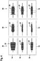
- FIG. 4 shows the schematic time course of the sensor signal 22 of an acceleration sensor 16 on the line 50 for water.
- the abscissa axes 72 each time is shown.
- the ordinate axes 74, 76 and 78 respectively represent the x, y and z components of the sensor signal 22 with respect to a Cartesian coordinate system.
- state 84 the sensor signal 22 of the acceleration sensor 16 is shown in the normal operating state.
- State 86 illustrates the course of the sensor signal 22 at a beginning loss of water. In this case, all components of the sensor signal 22 have lower maximum values and average values compared to the state 80.
- state 88 the sensor signals 22 are imaged at a critical loss of water. In this state 88, all components of the sensor signal 22 have strong fluctuations.
- the error variable 26 is determined in step 24 from an error function, which depends on at least one sensor signal 22.
- the choice of the error function depends on the technical and physical properties of the heating system 12 and / or the air conditioning or running in the heating system 12 and / or in the air conditioning processes, especially in fault conditions.
- the error function associated with a microphone signal may be logarithmic be to take into account the human volume impression.
- the error function with at least one sensor signal 22 is strictly monotonically increasing or decreasing.
- the error variable 26 is derived from a deviation of the sensor signal 22 from a desired signal specification 48 in step 24.
- the signal may be in the time domain or, as in FIG. 2 illustrated method 10, are compared in the frequency domain. In this case, mean values over a time and / or frequency range can also be used.
- the desired signal input 48 can be determined experimentally, for example, for different operating states of the heating system 12.
- the operating parameters 40 are determined in step 38 as a function of at least one error variable 26 as well as dependent on further sensor signals 22 and the old operating parameters.
- "old operating parameters" are to be understood as the operating parameters used prior to the execution of the method 10. In this way, the operating state of the heating system 12 and / or the air conditioning system is taken into account in the selection of the new operating parameters 40.
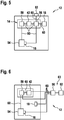
- the control unit 14 has a memory 42, a correction unit 56, a control unit 58 and an acceleration sensor 16 and a microphone 18.
- sensor signals 22 can be determined in step 20.
- the sensor signals 22 can be transmitted to the correction unit 56 via a communication connection 60.
- the correction unit 56 is set up such that the error signal 26 from the sensor signals 22 can be determined.
- the correction unit 56 is set up so that the step 30 can be executed so that a faulty state can be detected.
- the operating parameters 40 can be determined with the correction unit 56, depending on at least one error variable 26.
- the correction unit 56 has a communication connection 60 to a display unit 62, on which an error message 33 can be displayed.
- this is a TFT display with an associated control, by means of which the error indication signal of the correction unit 56 can be converted into a user-readable display display.
- the correction unit 56 has a communication connection 60 to the memory 42, so that the operating parameters 40 can be stored.
- the control unit 58 is set up so that components of the heating system 12 can be controlled.
- the control unit 58 has a communication connection 60 to a pump 54.
- the direction of rotation and the power of the pump 54 can thus be set by the transmission of control signals by the control unit 58.
- the acceleration sensor 16 is adhered to the pump 54.
- the adhesive used transmits vibrations.
- FIG. 6 shows a variant of the control unit 14 in the heating system 12.
- the correction unit 56 and the display unit 62 are designed to be mobile. Both elements of the control unit 14 are integrated in a portable diagnostic device 63, which can be used for diagnostic purposes.
- the communication links 60 between the correction unit 56 and the non-mobile parts of the control unit 14 are wireless Radio links, in this embodiment, are the connections via Zigbee. In alternative embodiments, WLAN, Bluetooth or Zwave is used.
- the correction unit 56 has a communication connection 60 to the control unit 58. In this way, step 34 is executable.
- At least one acceleration sensor 16 and / or at least one microphone 18 are also designed to be mobile. These may be present in a device with the mobile part of the control unit 14 or separately. To carry out a diagnosis then at least one acceleration sensor 16 and / or at least one microphone 18 in the heating system 12 are designed attachable. So they can be attached to designated components, preferably reversible, for example by clipping or screwing.
- At least one acceleration sensor 16 and / or one microphone 18 are permanently installed in a portable diagnostic device 63 together with the mobile parts of the control unit 14.
- the heating system 12 and / or the air conditioning system has or have a receptacle 64 suitable for the diagnostic device 63.
- FIG. 7 shows a variant of the heating system 12 with such a receptacle 64.
- the position of the receptacle 64 is selected so that the mobile acceleration sensor 16 can be attached by attaching the mobile diagnostic device 63 in the receptacle 64 on the pump 54.
- the receptacle 64 also has an interface that allows the communication link 60 between the mobile correction unit 56 and the non-mobile control unit 58.
- the correction unit 56 and / or the control unit 58 and / or the memory 42 may be partially or entirely in the form of software, which may be on internal or external devices, in particular mobile computing units, such as smartphones and tablets, or servers, in particular a cloud is running.
- the communication links 60 are then corresponding software interfaces.
- the control unit 14 or parts of the control unit 14 are provided by a mobile computing unit, in particular a smartphone or tablet.
- the portable diagnostic device 63 has at least one acceleration sensor 16 and / or a microphone 18 and a connection for a mobile computing unit, in particular a smartphone or tablet.
- the connection is intended for a communication connection 60 to the mobile computing unit.
- the communication link 60 between the mobile computing unit and the portable diagnostic device may be a wired connection or a wireless connection, in particular Bluetooth or WLAN. It is also conceivable that the mobile computing unit can be inserted into or connected to the portable diagnostic device 63, for example by a holder provided on the diagnostic device 63.
- the mobile computing unit receives data from the at least one acceleration sensor 16 and / or microphone 18 Computing unit provides the remaining mobile parts of the control unit 14, in particular the correction unit 56 and / or the control unit 58 and / or the memory 42, in particular wholly or partly in the form of software.
- the mobile computing unit can provide a display unit 62 and / or an input unit for user inputs, for example a touchscreen.
- At least one acceleration sensor 16 and / or microphone 18 of a mobile computing unit are used for the method 10.
- the mobile computing unit has the mobile parts of the control unit 14.
- the mobile computing unit has the at least one acceleration sensor 16 and / or microphone 18, the remaining mobile parts of the control unit can be completely or partially in the form of software.
- the receptacle 64 is adapted to receive the mobile computing unit.
- a heater 66 is shown as a realization of a heating system 12.
- an acceleration sensor 16 is attached to the pump 54, to the fan 44, to a heating cell 68, to the housing 70, to a line 50, to a valve 52 and to the control unit 14.
- the outside of the housing 70 has a microphone 18.
Landscapes
- Engineering & Computer Science (AREA)
- Mechanical Engineering (AREA)
- Physics & Mathematics (AREA)
- Thermal Sciences (AREA)
- Chemical & Material Sciences (AREA)
- Combustion & Propulsion (AREA)
- General Engineering & Computer Science (AREA)
- Air Conditioning Control Device (AREA)
Applications Claiming Priority (1)
| Application Number | Priority Date | Filing Date | Title |
|---|---|---|---|
| DE102016210418.7A DE102016210418A1 (de) | 2016-06-13 | 2016-06-13 | Verfahren und Steuereinheit zur Detektion von Fehlzuständen in einem Heizsystem und/oder in einer Klimaanlage sowie ein Heizsystem und/oder eine Klimaanlage |
Publications (2)
| Publication Number | Publication Date |
|---|---|
| EP3258183A1 true EP3258183A1 (fr) | 2017-12-20 |
| EP3258183B1 EP3258183B1 (fr) | 2023-08-09 |
Family
ID=59034622
Family Applications (1)
| Application Number | Title | Priority Date | Filing Date |
|---|---|---|---|
| EP17175406.2A Active EP3258183B1 (fr) | 2016-06-13 | 2017-06-12 | Procédé et unité de commande destinés à la détection de défaillances dans un système de chauffage et/ou dans un climatiseur et système de chauffage et/ou climatiseur |
Country Status (2)
| Country | Link |
|---|---|
| EP (1) | EP3258183B1 (fr) |
| DE (1) | DE102016210418A1 (fr) |
Cited By (1)
| Publication number | Priority date | Publication date | Assignee | Title |
|---|---|---|---|---|
| CN117167901A (zh) * | 2023-08-28 | 2023-12-05 | 珠海格力节能环保制冷技术研究中心有限公司 | 故障处理方法、装置、风盘机组、设备、介质和程序产品 |
Families Citing this family (3)
| Publication number | Priority date | Publication date | Assignee | Title |
|---|---|---|---|---|
| CN113719889B (zh) * | 2021-09-09 | 2023-04-07 | 中国电子信息产业集团有限公司第六研究所 | 一种区块链边缘流量安全控制方法、系统、电子设备 |
| DE102023108842A1 (de) * | 2023-04-06 | 2024-10-10 | Vaillant Gmbh | Verfahren zur Minderung der Geräuschemissionen eines HVAC-Systems, Regel- und Steuergerät, HVAC-System und Computerprogramm |
| DE102024120393A1 (de) * | 2024-07-18 | 2026-01-22 | Vaillant Gmbh | Verfahren zum Betreiben eines HVAC-Systems, HVAC-System und Computerprogramm |
Citations (6)
| Publication number | Priority date | Publication date | Assignee | Title |
|---|---|---|---|---|
| US20030200014A1 (en) * | 2002-04-17 | 2003-10-23 | Remboski Donald J. | Synchronous sampling of rotating elements in a fault detection system having audio analysis and method of using the same |
| EP2518414A1 (fr) * | 2009-12-25 | 2012-10-31 | Mitsubishi Electric Corporation | Climatiseur |
| US20130037620A1 (en) * | 2011-08-12 | 2013-02-14 | Qualcomm Incorporated | Controlling air movers based on acoustic signature |
| US20130166051A1 (en) * | 2011-12-21 | 2013-06-27 | Lennox Industries, Inc. | Hvac unit with audio monitoring, a method of audio monitoring events of an hvac unit and a controller configured to perform the method of audio monitoring |
| CN103527445A (zh) * | 2013-08-30 | 2014-01-22 | 青岛海信日立空调系统有限公司 | 一种空调及其噪声消除方法 |
| CN104848432A (zh) * | 2015-05-29 | 2015-08-19 | 东南大学 | 一种带主动降噪装置的空气净化器 |
Family Cites Families (4)
| Publication number | Priority date | Publication date | Assignee | Title |
|---|---|---|---|---|
| KR101242375B1 (ko) * | 2010-10-27 | 2013-03-14 | 엘지전자 주식회사 | 공기조화장치 |
| JP5592240B2 (ja) * | 2010-11-30 | 2014-09-17 | リンナイ株式会社 | 温風暖房機 |
| JP5627504B2 (ja) * | 2011-02-22 | 2014-11-19 | 三菱電機株式会社 | 空調設備保守システム及びデータ解析装置 |
| CN202126056U (zh) * | 2011-07-14 | 2012-01-25 | Tcl空调器(中山)有限公司 | 变频空调器 |
-
2016
- 2016-06-13 DE DE102016210418.7A patent/DE102016210418A1/de active Pending
-
2017
- 2017-06-12 EP EP17175406.2A patent/EP3258183B1/fr active Active
Patent Citations (6)
| Publication number | Priority date | Publication date | Assignee | Title |
|---|---|---|---|---|
| US20030200014A1 (en) * | 2002-04-17 | 2003-10-23 | Remboski Donald J. | Synchronous sampling of rotating elements in a fault detection system having audio analysis and method of using the same |
| EP2518414A1 (fr) * | 2009-12-25 | 2012-10-31 | Mitsubishi Electric Corporation | Climatiseur |
| US20130037620A1 (en) * | 2011-08-12 | 2013-02-14 | Qualcomm Incorporated | Controlling air movers based on acoustic signature |
| US20130166051A1 (en) * | 2011-12-21 | 2013-06-27 | Lennox Industries, Inc. | Hvac unit with audio monitoring, a method of audio monitoring events of an hvac unit and a controller configured to perform the method of audio monitoring |
| CN103527445A (zh) * | 2013-08-30 | 2014-01-22 | 青岛海信日立空调系统有限公司 | 一种空调及其噪声消除方法 |
| CN104848432A (zh) * | 2015-05-29 | 2015-08-19 | 东南大学 | 一种带主动降噪装置的空气净化器 |
Cited By (1)
| Publication number | Priority date | Publication date | Assignee | Title |
|---|---|---|---|---|
| CN117167901A (zh) * | 2023-08-28 | 2023-12-05 | 珠海格力节能环保制冷技术研究中心有限公司 | 故障处理方法、装置、风盘机组、设备、介质和程序产品 |
Also Published As
| Publication number | Publication date |
|---|---|
| EP3258183B1 (fr) | 2023-08-09 |
| DE102016210418A1 (de) | 2017-12-14 |
Similar Documents
| Publication | Publication Date | Title |
|---|---|---|
| EP2697572B1 (fr) | Systeme et methode de diagnostique automatique de fonction | |
| EP3258183B1 (fr) | Procédé et unité de commande destinés à la détection de défaillances dans un système de chauffage et/ou dans un climatiseur et système de chauffage et/ou climatiseur | |
| EP2475920B1 (fr) | Système de diagnostic pour une soupape | |
| DE102005003251B4 (de) | Verfahren zum Prüfen und zum Bestimmen der Irrationalität eines Motorkühltemperaturfühlers in einem Fahrzeug | |
| DE102017200855B4 (de) | Verfahren und System zur Diagnose eines Zustands eines Dämpfungssystems eines Fahrzeugs | |
| DE102007010768B4 (de) | Verfahren für die Optimierung der Ventilstellung und der Pumpendrehzahl in einem Ventilsystem mit PID-Regelung ohne die Verwendung externer Signale | |
| CN109654662B (zh) | 检测元件控制方法、装置及空调机组 | |
| DE102008058208B4 (de) | Stellgerät und Verfahren zur Überprüfung der korrekten Funktionsfähigkeit eines Faltenbalges eines Stellgerätes | |
| DE102016124035B4 (de) | Verfahren zum Diagnostizieren eines Ausfalls einer Leistungsstufe eines elektronischen Wastegateaktuators | |
| WO2024042017A1 (fr) | Système et procédé de surveillance d'un système avec un composant système pouvant être commandé | |
| WO2021244869A1 (fr) | Procédé de fonctionnement d'un dispositif de surveillance pour surveiller une installation de chauffage, dispositif de surveillance et installation de chauffage comprenant le dispositif de surveillance | |
| DE10254485B4 (de) | Kraftfahrzeug | |
| EP2045158B1 (fr) | Dispositif d'alimentation en air comprimé doté d'une analyse des fuites et procédé de fonctionnement d'un tel dispositif d'alimentation en air comprimé | |
| EP3712502A1 (fr) | Procédé de vérification de l'existence d'un clapet anti-retour dans une installation de chauffage | |
| DE102019206784A1 (de) | Verfahren und Anordnung zur Zustandsbestimmung einer Batterievorrichtung | |
| WO2014161542A1 (fr) | Procédé de mise en service automatique d'une boîte de vitesses de véhicule automobile | |
| DE102020105066B4 (de) | Verfahren zum Betreiben einer Kontrollanzeigeeinrichtung, Wartungsüberwachungseinrichtung, Kraftfahrzeug, und Servervorrichtung | |
| WO2008128598A1 (fr) | Procédé de diagnostic de systèmes techniques, en particulier pour véhicule automobile | |
| EP4086526B1 (fr) | Procédé de surveillance d'une installation de chauffage, programme informatique, appareil de régulation et de commande, installation de chauffage et utilisation des données de fonctionnement d'une installation de chauffage | |
| DE102007001452A1 (de) | Verfahren und Vorrichtung zur Ermittlung einer Kältemittelunterfüllung eines Kältemittelkreislaufs einer Klimaanlage für ein Fahrzeug | |
| US20240230140A1 (en) | An hvac system and related methods | |
| CN106227193A (zh) | 一种汽车故障诊断系统及其诊断方法 | |
| DE102016209450A1 (de) | Verfahren zur Überwachung einer Entlüftung eines Kurbelgehäuses | |
| DE102005031552B4 (de) | Verfahren zur Betriebsprüfung einer Messeinrichtung | |
| EP3433693B1 (fr) | Procédé et système de surveillance d'un dispositif de base par un terminal mobile |
Legal Events
| Date | Code | Title | Description |
|---|---|---|---|
| PUAI | Public reference made under article 153(3) epc to a published international application that has entered the european phase |
Free format text: ORIGINAL CODE: 0009012 |
|
| STAA | Information on the status of an ep patent application or granted ep patent |
Free format text: STATUS: THE APPLICATION HAS BEEN PUBLISHED |
|
| AK | Designated contracting states |
Kind code of ref document: A1 Designated state(s): AL AT BE BG CH CY CZ DE DK EE ES FI FR GB GR HR HU IE IS IT LI LT LU LV MC MK MT NL NO PL PT RO RS SE SI SK SM TR |
|
| AX | Request for extension of the european patent |
Extension state: BA ME |
|
| STAA | Information on the status of an ep patent application or granted ep patent |
Free format text: STATUS: REQUEST FOR EXAMINATION WAS MADE |
|
| 17P | Request for examination filed |
Effective date: 20180620 |
|
| RBV | Designated contracting states (corrected) |
Designated state(s): AL AT BE BG CH CY CZ DE DK EE ES FI FR GB GR HR HU IE IS IT LI LT LU LV MC MK MT NL NO PL PT RO RS SE SI SK SM TR |
|
| STAA | Information on the status of an ep patent application or granted ep patent |
Free format text: STATUS: EXAMINATION IS IN PROGRESS |
|
| RAP1 | Party data changed (applicant data changed or rights of an application transferred) |
Owner name: ROBERT BOSCH GMBH |
|
| 17Q | First examination report despatched |
Effective date: 20200421 |
|
| REG | Reference to a national code |
Ref country code: DE Ref legal event code: R079 Free format text: PREVIOUS MAIN CLASS: F24F0011000000 Ipc: F24F0011300000 Ref country code: DE Ref legal event code: R079 Ref document number: 502017015166 Country of ref document: DE Free format text: PREVIOUS MAIN CLASS: F24F0011000000 Ipc: F24F0011300000 |
|
| RIC1 | Information provided on ipc code assigned before grant |
Ipc: B60H 1/00 20060101ALI20221129BHEP Ipc: F24F 130/40 20180101ALI20221129BHEP Ipc: F24F 110/00 20180101ALI20221129BHEP Ipc: F24F 11/30 20180101AFI20221129BHEP |
|
| GRAP | Despatch of communication of intention to grant a patent |
Free format text: ORIGINAL CODE: EPIDOSNIGR1 |
|
| STAA | Information on the status of an ep patent application or granted ep patent |
Free format text: STATUS: GRANT OF PATENT IS INTENDED |
|
| INTG | Intention to grant announced |
Effective date: 20230309 |
|
| GRAS | Grant fee paid |
Free format text: ORIGINAL CODE: EPIDOSNIGR3 |
|
| GRAA | (expected) grant |
Free format text: ORIGINAL CODE: 0009210 |
|
| STAA | Information on the status of an ep patent application or granted ep patent |
Free format text: STATUS: THE PATENT HAS BEEN GRANTED |
|
| AK | Designated contracting states |
Kind code of ref document: B1 Designated state(s): AL AT BE BG CH CY CZ DE DK EE ES FI FR GB GR HR HU IE IS IT LI LT LU LV MC MK MT NL NO PL PT RO RS SE SI SK SM TR |
|
| REG | Reference to a national code |
Ref country code: GB Ref legal event code: FG4D Free format text: NOT ENGLISH |
|
| REG | Reference to a national code |
Ref country code: CH Ref legal event code: EP |
|
| REG | Reference to a national code |
Ref country code: IE Ref legal event code: FG4D Free format text: LANGUAGE OF EP DOCUMENT: GERMAN |
|
| REG | Reference to a national code |
Ref country code: DE Ref legal event code: R096 Ref document number: 502017015166 Country of ref document: DE |
|
| REG | Reference to a national code |
Ref country code: SE Ref legal event code: TRGR |
|
| REG | Reference to a national code |
Ref country code: NL Ref legal event code: FP |
|
| REG | Reference to a national code |
Ref country code: LT Ref legal event code: MG9D |
|
| PG25 | Lapsed in a contracting state [announced via postgrant information from national office to epo] |
Ref country code: GR Free format text: LAPSE BECAUSE OF FAILURE TO SUBMIT A TRANSLATION OF THE DESCRIPTION OR TO PAY THE FEE WITHIN THE PRESCRIBED TIME-LIMIT Effective date: 20231110 |
|
| PG25 | Lapsed in a contracting state [announced via postgrant information from national office to epo] |
Ref country code: IS Free format text: LAPSE BECAUSE OF FAILURE TO SUBMIT A TRANSLATION OF THE DESCRIPTION OR TO PAY THE FEE WITHIN THE PRESCRIBED TIME-LIMIT Effective date: 20231209 |
|
| PG25 | Lapsed in a contracting state [announced via postgrant information from national office to epo] |
Ref country code: RS Free format text: LAPSE BECAUSE OF FAILURE TO SUBMIT A TRANSLATION OF THE DESCRIPTION OR TO PAY THE FEE WITHIN THE PRESCRIBED TIME-LIMIT Effective date: 20230809 Ref country code: PT Free format text: LAPSE BECAUSE OF FAILURE TO SUBMIT A TRANSLATION OF THE DESCRIPTION OR TO PAY THE FEE WITHIN THE PRESCRIBED TIME-LIMIT Effective date: 20231211 Ref country code: NO Free format text: LAPSE BECAUSE OF FAILURE TO SUBMIT A TRANSLATION OF THE DESCRIPTION OR TO PAY THE FEE WITHIN THE PRESCRIBED TIME-LIMIT Effective date: 20231109 Ref country code: LV Free format text: LAPSE BECAUSE OF FAILURE TO SUBMIT A TRANSLATION OF THE DESCRIPTION OR TO PAY THE FEE WITHIN THE PRESCRIBED TIME-LIMIT Effective date: 20230809 Ref country code: LT Free format text: LAPSE BECAUSE OF FAILURE TO SUBMIT A TRANSLATION OF THE DESCRIPTION OR TO PAY THE FEE WITHIN THE PRESCRIBED TIME-LIMIT Effective date: 20230809 Ref country code: IS Free format text: LAPSE BECAUSE OF FAILURE TO SUBMIT A TRANSLATION OF THE DESCRIPTION OR TO PAY THE FEE WITHIN THE PRESCRIBED TIME-LIMIT Effective date: 20231209 Ref country code: HR Free format text: LAPSE BECAUSE OF FAILURE TO SUBMIT A TRANSLATION OF THE DESCRIPTION OR TO PAY THE FEE WITHIN THE PRESCRIBED TIME-LIMIT Effective date: 20230809 Ref country code: GR Free format text: LAPSE BECAUSE OF FAILURE TO SUBMIT A TRANSLATION OF THE DESCRIPTION OR TO PAY THE FEE WITHIN THE PRESCRIBED TIME-LIMIT Effective date: 20231110 Ref country code: FI Free format text: LAPSE BECAUSE OF FAILURE TO SUBMIT A TRANSLATION OF THE DESCRIPTION OR TO PAY THE FEE WITHIN THE PRESCRIBED TIME-LIMIT Effective date: 20230809 |
|
| PG25 | Lapsed in a contracting state [announced via postgrant information from national office to epo] |
Ref country code: PL Free format text: LAPSE BECAUSE OF FAILURE TO SUBMIT A TRANSLATION OF THE DESCRIPTION OR TO PAY THE FEE WITHIN THE PRESCRIBED TIME-LIMIT Effective date: 20230809 |
|
| PG25 | Lapsed in a contracting state [announced via postgrant information from national office to epo] |
Ref country code: ES Free format text: LAPSE BECAUSE OF FAILURE TO SUBMIT A TRANSLATION OF THE DESCRIPTION OR TO PAY THE FEE WITHIN THE PRESCRIBED TIME-LIMIT Effective date: 20230809 |
|
| PG25 | Lapsed in a contracting state [announced via postgrant information from national office to epo] |
Ref country code: SM Free format text: LAPSE BECAUSE OF FAILURE TO SUBMIT A TRANSLATION OF THE DESCRIPTION OR TO PAY THE FEE WITHIN THE PRESCRIBED TIME-LIMIT Effective date: 20230809 Ref country code: RO Free format text: LAPSE BECAUSE OF FAILURE TO SUBMIT A TRANSLATION OF THE DESCRIPTION OR TO PAY THE FEE WITHIN THE PRESCRIBED TIME-LIMIT Effective date: 20230809 Ref country code: ES Free format text: LAPSE BECAUSE OF FAILURE TO SUBMIT A TRANSLATION OF THE DESCRIPTION OR TO PAY THE FEE WITHIN THE PRESCRIBED TIME-LIMIT Effective date: 20230809 Ref country code: EE Free format text: LAPSE BECAUSE OF FAILURE TO SUBMIT A TRANSLATION OF THE DESCRIPTION OR TO PAY THE FEE WITHIN THE PRESCRIBED TIME-LIMIT Effective date: 20230809 Ref country code: DK Free format text: LAPSE BECAUSE OF FAILURE TO SUBMIT A TRANSLATION OF THE DESCRIPTION OR TO PAY THE FEE WITHIN THE PRESCRIBED TIME-LIMIT Effective date: 20230809 Ref country code: CZ Free format text: LAPSE BECAUSE OF FAILURE TO SUBMIT A TRANSLATION OF THE DESCRIPTION OR TO PAY THE FEE WITHIN THE PRESCRIBED TIME-LIMIT Effective date: 20230809 Ref country code: SK Free format text: LAPSE BECAUSE OF FAILURE TO SUBMIT A TRANSLATION OF THE DESCRIPTION OR TO PAY THE FEE WITHIN THE PRESCRIBED TIME-LIMIT Effective date: 20230809 |
|
| REG | Reference to a national code |
Ref country code: DE Ref legal event code: R097 Ref document number: 502017015166 Country of ref document: DE |
|
| PG25 | Lapsed in a contracting state [announced via postgrant information from national office to epo] |
Ref country code: IT Free format text: LAPSE BECAUSE OF FAILURE TO SUBMIT A TRANSLATION OF THE DESCRIPTION OR TO PAY THE FEE WITHIN THE PRESCRIBED TIME-LIMIT Effective date: 20230809 |
|
| PLBE | No opposition filed within time limit |
Free format text: ORIGINAL CODE: 0009261 |
|
| STAA | Information on the status of an ep patent application or granted ep patent |
Free format text: STATUS: NO OPPOSITION FILED WITHIN TIME LIMIT |
|
| 26N | No opposition filed |
Effective date: 20240513 |
|
| PG25 | Lapsed in a contracting state [announced via postgrant information from national office to epo] |
Ref country code: SI Free format text: LAPSE BECAUSE OF FAILURE TO SUBMIT A TRANSLATION OF THE DESCRIPTION OR TO PAY THE FEE WITHIN THE PRESCRIBED TIME-LIMIT Effective date: 20230809 |
|
| PG25 | Lapsed in a contracting state [announced via postgrant information from national office to epo] |
Ref country code: BG Free format text: LAPSE BECAUSE OF FAILURE TO SUBMIT A TRANSLATION OF THE DESCRIPTION OR TO PAY THE FEE WITHIN THE PRESCRIBED TIME-LIMIT Effective date: 20230809 |
|
| PG25 | Lapsed in a contracting state [announced via postgrant information from national office to epo] |
Ref country code: BG Free format text: LAPSE BECAUSE OF FAILURE TO SUBMIT A TRANSLATION OF THE DESCRIPTION OR TO PAY THE FEE WITHIN THE PRESCRIBED TIME-LIMIT Effective date: 20230809 |
|
| PG25 | Lapsed in a contracting state [announced via postgrant information from national office to epo] |
Ref country code: MC Free format text: LAPSE BECAUSE OF FAILURE TO SUBMIT A TRANSLATION OF THE DESCRIPTION OR TO PAY THE FEE WITHIN THE PRESCRIBED TIME-LIMIT Effective date: 20230809 |
|
| REG | Reference to a national code |
Ref country code: CH Ref legal event code: PL |
|
| PG25 | Lapsed in a contracting state [announced via postgrant information from national office to epo] |
Ref country code: LU Free format text: LAPSE BECAUSE OF NON-PAYMENT OF DUE FEES Effective date: 20240612 |
|
| PG25 | Lapsed in a contracting state [announced via postgrant information from national office to epo] |
Ref country code: IE Free format text: LAPSE BECAUSE OF NON-PAYMENT OF DUE FEES Effective date: 20240612 |
|
| PG25 | Lapsed in a contracting state [announced via postgrant information from national office to epo] |
Ref country code: BE Free format text: LAPSE BECAUSE OF NON-PAYMENT OF DUE FEES Effective date: 20240630 Ref country code: CH Free format text: LAPSE BECAUSE OF NON-PAYMENT OF DUE FEES Effective date: 20240630 |
|
| REG | Reference to a national code |
Ref country code: BE Ref legal event code: MM Effective date: 20240630 |
|
| PGFP | Annual fee paid to national office [announced via postgrant information from national office to epo] |
Ref country code: GB Payment date: 20250620 Year of fee payment: 9 |
|
| PGFP | Annual fee paid to national office [announced via postgrant information from national office to epo] |
Ref country code: NL Payment date: 20250618 Year of fee payment: 9 |
|
| PGFP | Annual fee paid to national office [announced via postgrant information from national office to epo] |
Ref country code: FR Payment date: 20250626 Year of fee payment: 9 |
|
| PGFP | Annual fee paid to national office [announced via postgrant information from national office to epo] |
Ref country code: SE Payment date: 20250618 Year of fee payment: 9 |
|
| REG | Reference to a national code |
Ref country code: AT Ref legal event code: MM01 Ref document number: 1597943 Country of ref document: AT Kind code of ref document: T Effective date: 20240612 |
|
| PGFP | Annual fee paid to national office [announced via postgrant information from national office to epo] |
Ref country code: DE Payment date: 20250814 Year of fee payment: 9 |
|
| PG25 | Lapsed in a contracting state [announced via postgrant information from national office to epo] |
Ref country code: AT Free format text: LAPSE BECAUSE OF NON-PAYMENT OF DUE FEES Effective date: 20240612 |
|
| PG25 | Lapsed in a contracting state [announced via postgrant information from national office to epo] |
Ref country code: CY Free format text: LAPSE BECAUSE OF FAILURE TO SUBMIT A TRANSLATION OF THE DESCRIPTION OR TO PAY THE FEE WITHIN THE PRESCRIBED TIME-LIMIT; INVALID AB INITIO Effective date: 20170612 |
|
| PG25 | Lapsed in a contracting state [announced via postgrant information from national office to epo] |
Ref country code: HU Free format text: LAPSE BECAUSE OF FAILURE TO SUBMIT A TRANSLATION OF THE DESCRIPTION OR TO PAY THE FEE WITHIN THE PRESCRIBED TIME-LIMIT; INVALID AB INITIO Effective date: 20170612 |