EP3258206A1 - Tragbares nutzlastträgersystem - Google Patents
Tragbares nutzlastträgersystem Download PDFInfo
- Publication number
- EP3258206A1 EP3258206A1 EP17153642.8A EP17153642A EP3258206A1 EP 3258206 A1 EP3258206 A1 EP 3258206A1 EP 17153642 A EP17153642 A EP 17153642A EP 3258206 A1 EP3258206 A1 EP 3258206A1
- Authority
- EP
- European Patent Office
- Prior art keywords
- cartridge
- payload
- firing pin
- launcher
- chamber
- Prior art date
- Legal status (The legal status is an assumption and is not a legal conclusion. Google has not performed a legal analysis and makes no representation as to the accuracy of the status listed.)
- Withdrawn
Links
- 239000000126 substance Substances 0.000 claims abstract description 48
- 238000000034 method Methods 0.000 claims abstract description 40
- 239000000700 radioactive tracer Substances 0.000 claims abstract description 11
- 230000011664 signaling Effects 0.000 claims abstract description 11
- 239000000779 smoke Substances 0.000 claims abstract description 11
- 231100001160 nonlethal Toxicity 0.000 claims abstract description 10
- 238000010304 firing Methods 0.000 claims description 137
- 239000003380 propellant Substances 0.000 claims description 52
- 239000000843 powder Substances 0.000 claims description 11
- 230000000717 retained effect Effects 0.000 claims description 6
- 239000007788 liquid Substances 0.000 claims description 5
- 239000004505 smoke cartridge Substances 0.000 claims description 5
- 239000002360 explosive Substances 0.000 abstract description 6
- 238000007599 discharging Methods 0.000 abstract description 5
- 239000003550 marker Substances 0.000 abstract description 5
- 239000007789 gas Substances 0.000 description 17
- 239000000463 material Substances 0.000 description 10
- 230000007246 mechanism Effects 0.000 description 9
- 230000001629 suppression Effects 0.000 description 9
- 239000000499 gel Substances 0.000 description 8
- 239000000203 mixture Substances 0.000 description 8
- 230000008901 benefit Effects 0.000 description 4
- 230000033001 locomotion Effects 0.000 description 4
- CURLTUGMZLYLDI-UHFFFAOYSA-N Carbon dioxide Chemical compound O=C=O CURLTUGMZLYLDI-UHFFFAOYSA-N 0.000 description 3
- 238000005516 engineering process Methods 0.000 description 3
- 238000007726 management method Methods 0.000 description 3
- 238000012986 modification Methods 0.000 description 3
- 230000004048 modification Effects 0.000 description 3
- 239000004033 plastic Substances 0.000 description 3
- 230000003213 activating effect Effects 0.000 description 2
- 229910002092 carbon dioxide Inorganic materials 0.000 description 2
- 239000002131 composite material Substances 0.000 description 2
- 230000001066 destructive effect Effects 0.000 description 2
- 239000006185 dispersion Substances 0.000 description 2
- 230000000116 mitigating effect Effects 0.000 description 2
- 230000037452 priming Effects 0.000 description 2
- 239000007787 solid Substances 0.000 description 2
- 230000001960 triggered effect Effects 0.000 description 2
- 235000002566 Capsicum Nutrition 0.000 description 1
- 240000008574 Capsicum frutescens Species 0.000 description 1
- 244000046052 Phaseolus vulgaris Species 0.000 description 1
- 235000010627 Phaseolus vulgaris Nutrition 0.000 description 1
- 208000027418 Wounds and injury Diseases 0.000 description 1
- 230000009471 action Effects 0.000 description 1
- 230000004913 activation Effects 0.000 description 1
- 239000012190 activator Substances 0.000 description 1
- 239000000654 additive Substances 0.000 description 1
- 230000004888 barrier function Effects 0.000 description 1
- 239000011449 brick Substances 0.000 description 1
- 239000001390 capsicum minimum Substances 0.000 description 1
- 239000001569 carbon dioxide Substances 0.000 description 1
- 239000003795 chemical substances by application Substances 0.000 description 1
- 239000002575 chemical warfare agent Substances 0.000 description 1
- 238000010276 construction Methods 0.000 description 1
- 230000006378 damage Effects 0.000 description 1
- 231100001261 hazardous Toxicity 0.000 description 1
- 208000014674 injury Diseases 0.000 description 1
- 238000007689 inspection Methods 0.000 description 1
- 238000012423 maintenance Methods 0.000 description 1
- 230000014759 maintenance of location Effects 0.000 description 1
- 239000002184 metal Substances 0.000 description 1
- 239000008601 oleoresin Substances 0.000 description 1
- 239000002245 particle Substances 0.000 description 1
- 239000008188 pellet Substances 0.000 description 1
- 230000000149 penetrating effect Effects 0.000 description 1
- IMACFCSSMIZSPP-UHFFFAOYSA-N phenacyl chloride Chemical compound ClCC(=O)C1=CC=CC=C1 IMACFCSSMIZSPP-UHFFFAOYSA-N 0.000 description 1
- 229920000642 polymer Polymers 0.000 description 1
- -1 pyrotechnic Substances 0.000 description 1
- 230000009467 reduction Effects 0.000 description 1
- 239000011435 rock Substances 0.000 description 1
- 238000005096 rolling process Methods 0.000 description 1
- 238000007789 sealing Methods 0.000 description 1
- 238000005507 spraying Methods 0.000 description 1
- 239000003491 tear gas Substances 0.000 description 1
Images


Classifications
-
- F—MECHANICAL ENGINEERING; LIGHTING; HEATING; WEAPONS; BLASTING
- F41—WEAPONS
- F41C—SMALLARMS, e.g. PISTOLS, RIFLES; ACCESSORIES THEREFOR
- F41C9/00—Other smallarms, e.g. hidden smallarms or smallarms specially adapted for underwater use
- F41C9/08—Muzzle-loading smallarms; Smallarms with flintlock mechanisms; Accessories therefor
-
- F—MECHANICAL ENGINEERING; LIGHTING; HEATING; WEAPONS; BLASTING
- F41—WEAPONS
- F41C—SMALLARMS, e.g. PISTOLS, RIFLES; ACCESSORIES THEREFOR
- F41C3/00—Pistols, e.g. revolvers
- F41C3/02—Signal pistols, e.g. Very pistols
-
- F—MECHANICAL ENGINEERING; LIGHTING; HEATING; WEAPONS; BLASTING
- F41—WEAPONS
- F41F—APPARATUS FOR LAUNCHING PROJECTILES OR MISSILES FROM BARRELS, e.g. CANNONS; LAUNCHERS FOR ROCKETS OR TORPEDOES; HARPOON GUNS
- F41F1/00—Launching apparatus for projecting projectiles or missiles from barrels, e.g. cannons; Harpoon guns
- F41F1/06—Mortars
-
- F—MECHANICAL ENGINEERING; LIGHTING; HEATING; WEAPONS; BLASTING
- F42—AMMUNITION; BLASTING
- F42B—EXPLOSIVE CHARGES, e.g. FOR BLASTING, FIREWORKS, AMMUNITION
- F42B5/00—Cartridge ammunition, e.g. separately-loaded propellant charges
- F42B5/02—Cartridges, i.e. cases with charge and missile
- F42B5/145—Cartridges, i.e. cases with charge and missile for dispensing gases, vapours, powders, particles or chemically-reactive substances
Definitions
- This disclosure relates to systems for discharging payloads, including chemical payloads, to downrange targets.
- Cartridge systems that contain a particular payload to be launched constitute extremely practical constructions for deploying almost any material or projectile downrange.
- Typical cartridge systems incorporate the desired payload, a propellant, and some priming composition all within a self-contained unit.
- ammunition cartridges are prototypical of cartridge devices, useful cartridge systems have been designed to launch other payloads, such as chemical, pyrotechnic, marker, tracer, signaling, non-lethal projectiles, explosive, smoke, and the like, to exploit their specific functions.
- This disclosure relates to launchers and launcher systems for discharging or deploying payloads such as chemical payloads to downrange targets, including those at close ranges, and the methods of using launcher systems for deploying payloads to the desired target.
- These devices and methods include means for managing recoil when using the disclosed launcher systems.
- payloads that can be launched with the disclosed system include chemical, biological, pyrotechnic, marker, tracer, signaling, non-lethal projectile, explosive, smoke, and the like.
- the device and method are not limited to any particular cartridge design or payload. Thus, the device and method can be used with separate cartridges, integral cartridge components, multi-cartridge or multi-component cartridge embodiments, and any other type cartridge system.
- launcher systems include their ability to be carried by an individual and typically handheld, and incorporating a means of managing recoil when launching any payload. While not intending to be limiting, preferred uses of the disclosed launcher system include launching a chemical payload at close range such as used for fire suppression, or deploying a heat barrier, or launching a chemical payload at close range directly at personnel, with the intent to cover the individual with a fire suppression or anti-chemical warfare substance. Thus, a wide range of cartridge arrangements and muzzle velocities are useful with this device.
- this disclosure provide a payload launcher system comprising:
- this disclosure provides a method of launching a payload, the method comprising:
- This disclosure relates to launchers and launcher systems for discharging various payloads to downrange targets, including those at close ranges, and the methods of using launcher systems for deploying the payloads to the desired target.
- These devices and methods include means for managing recoil when using the disclosed launcher systems, and the device and method are not limited to any particular cartridge design or particular payload.
- the device and method can be used with separate cartridges, integral cartridge components, multi-cartridge or multi-component cartridge embodiments, and any other type cartridge system.
- the launcher system can be used in combination with a separate self-contained cartridge that is adapted for use with the recoilmanaged launcher, as described herein.
- the cartridge itself can comprise the primer, propellant, the payload, and any ancillary components such as wad systems, in a single self-contained cartridge.
- the launcher is capable of being re-loaded by the user immediately after its discharge, for sending additional payload or a different payload downrange.
- the launcher system is not limited to a particular payload type.
- the payload can comprise or can be selected from chemical, powder, gel, fire suppression, pyrotechnic, marker, tracer, signaling, non-lethal projectile, frangible, antipersonnel, explosive, smoke, incendiary, biological, heat insulating, anti-chemical warfare, anti-biological warfare, liquid-containing, powder-containing, and gel-containing payloads.
- a flare cartridge for example, a smoke cartridge, a smoke flare cartridge, a signaling device cartridge, a chemical cartridge, a biological cartridge, a distraction device cartridge, a pyrotechnic cartridge, an antipersonnel cartridge, a marking cartridge, an incendiary cartridge, a tracer cartridge, a non-lethal projectile cartridge, an anti-chemical warfare cartridge, or anti-biological warfare cartridge, and the like, can all be employed with the disclosed launcher.
- the pre-loaded launcher when the pre-loaded, it can comprise or can be selected from these types of payloads and components.
- the launcher itself can be pre-loaded to include the primer, propellant, payload and any necessary ancillary components such as wad systems for launching the payload, without the requirement for a separate "hull" or cartridge case.
- such launcher devices are typically pre-loaded at the factory to include these components.
- no separate cartridge unit is required, and the pre-loaded device does not require any other gun or launching mechanism to fire or discharge the payload.
- This pre-loaded embodiment of the launcher system would be desirable when, for example, a single-use or one-shot device in which the launcher housing is a disposable and can be discarded after use, or the launcher housing can be saved and reloaded, for example, at a field facility or at the factory.
- the launcher system can be constructed or loaded using any type of blank-type (“blank”) cartridge for propulsion, which fit into a chamber or sub-chamber designed to accept such cartridges.
- a separate payload can be muzzle loaded into the payload sub-chamber of the launcher system, with a primer in the blank propulsion cartridge at the aft or rearward end of the launcher in the propellant sub-chamber, and the payload at the muzzle or forward end of the launcher.
- These launcher systems use a first propellant cartridge that generates rapidly expanding propellant gases, in combination with a separate payload or projectile component, sometimes in cartridge form, that is distinct from the propellant cartridge.
- a blank propulsion cartridge is typically sufficient, although a relatively small primary charge can be used if desired.
- these two-component or multi-component (primer-propellant component separate from payload component) launchers can be used with a so-called "wadless" obturating medium situated between the primer at the aft end and the payload at the muzzle end, such that propellant gases are effectively sealed upon igniting the propellant with the primer to launch the payload.
- wadless technology can be advantageously used in this manner for launching dry chemicals such as those used for fire suppression and the like.
- the launcher system is designed to be carried by an individual, for example, hand carried or in some manner carried on a person.
- Embodiments include launcher systems that can fit into an adult hand for use, regardless of that type cartridge system used with the launcher. Because of the simple recoil-management method, the disclosed devices are capable of handling and launching larger payloads than if the device is simply handheld and the primer strike was triggered in the conventional fashion. Accordingly, this disclosure provides a handheld launcher device particularly suited for use in the dangerous environments of combat or law enforcement situations, due to the device's light weight, portability, and ease of operation. Particularly advantageous features of the launcher system include the ability to rapidly cover an area-including personnel within that area-with a chemical payload such as fire suppression chemicals, anti-chemical warfare substances, or anti-biological warfare substances.
- embodiments of the launcher system can be devoid of a conventional trigger or trigger mechanism, trigger spring, hammer, sear, locking block, barrel, magazine, recoil spring, gas tube, slide, frame, bolt, locking block, conventional receiver, cylinder, typical safety mechanism, ejector, conventional extractor, guide rod, spring housing, a rail, decocker, stock, and the like.
- trigger spring trigger spring
- hammer sear
- locking block barrel
- magazine recoil spring
- gas tube slide, frame, bolt
- locking block conventional receiver
- typical safety mechanism ejector, conventional extractor, guide rod, spring housing, a rail, decocker, stock, and the like.
- the firing mechanism is simple, many of these conventional components can be omitted.
- the comparatively low muzzle velocities do not require the launch and cartridge to accommodate high pressures upon firing, and therefore, conventional locking block and barrel components are not required.
- some of these components that can be included in the launcher system although not shown in the figures, include extractor mechanisms for
- the payload launcher system 5 of this disclosure can include a launcher tube 10 having a nozzle end 15 and an aft end 20, the aft end of which can be threaded if desired with threads 25 or a twist-lock mechanism that match the threads or twist-lock feature on a cap 30.
- the end cap 30 comprises a firing pin opening 35 through which the tip of the firing pin will protrude to contact the primer when the firing pin 50 is struck.
- Cap 30 also includes a hinge 40 one on side of the opening 35 and a safety pin receptacle 45 on the opposite side of the opening 35.
- the firing pin 50 is moveably attached, for example as shown in the figures, rotatably attached, to the cap 30 at hinge 40 at the hinge portion 55 of the firing pin, for example, with a hinge pin 43 (not shown) that secures the hinge portion 55 and hence the firing pin 50 to the cap at hinge 40.
- a hinge pin 43 (not shown) that secures the hinge portion 55 and hence the firing pin 50 to the cap at hinge 40.
- the safety arm 60 of the firing pin which is retained from forward motion by a safety pin 65 (not shown) that extends through the safety pin receptacle 45 on the cap 30.
- the safety pin 65 can be a cotter key type pin or similar "fire extinguisher" type pin that is sufficiently secure that it requires significant force to be extracted from its retention position.
- the firing pin can be struck with a solid object, including for example a hand, a pistol, or a brick, or alternatively, the firing pin of the device can be struck against a solid object, such as a wall, a post, or a vehicle, either of which drive the point of the firing pin to strike the primer.
- a solid object such as a wall, a post, or a vehicle, either of which drive the point of the firing pin to strike the primer.
- activation as disclosed herein also provides a means to achieve recoil management or recoil reduction.
- recoil is either at least partially offset by the momentum created when the entire unit is moved forward when struck with a hand, pistol butt, rock or other object as described, or recoil is at least partially offset by striking the aft end of the launcher against the substantially immovable object such as a wall or a vehicle.
- the primer is associated with the blank cartridge located in the propellant sub-chamber. In this manner, the launcher will be activated to expend the desired payload from chamber to the selected target, and regardless of the cartridge design, recoil can be managed in this manner.
- the chamber 70 can extend from the aft end the entire distance to the nozzle end.
- there can be steps within the chamber if it is desired to secure or "headspace" the self-contained cartridge at its forward end.
- the chamber will incorporate a slightly larger diameter aft end, sufficient to accommodate a slightly larger diameter aft end of the self-contained cartridge, for example, shaped similarly to a shotshell.
- the chamber 70 does not require separate sub-chambers to accommodate a separate primer component and a separate payload component, because the self-contained cartridge comprises the primer, optional propellant, and payload.
- the overall chamber typically comprises a first sub-chamber 75, sometimes termed a propellant sub-chamber, within the launcher tube adjacent the firing pin opening, and a second sub-chamber 80, sometimes termed a payload sub-chamber, within the launcher tube adjacent and forward of the propellant sub-chamber.
- the first sub-chamber 75 is shaped to receive a first self-contained cartridge comprising the primer
- the second sub-chamber 80 is shaped to receive a second self-contained cartridge comprising the payload.
- the propellant sub-chamber 75 and the payload sub-chamber 80 also can be separated by an obturating component, optionally in its own sub-chamber, separating the propellant and the payload.
- Suitable obturating components include the so-called "wadless" technology described in U.S. Patent No. 7,814,820 and U.S. Patent Application Publication No. 2011/0017090 by Menefee , both of which are incorporated herein by reference in their entireties.
- wadless technology may be useful in launching powders and gels and the like relatively short distances, such as in cartridge launcher designed for distributing powders rapidly indoors or generally within closed confines.
- the obturating component systems can be used in can be used in self-contained cartridges to launch any of the disclosed payloads.
- self-contained cartridges comprising a wadless obturating medium also can be used in launching powders and gels relatively short distances.
- FIG. 1 illustrates exploded views of a representative embodiment of a handheld payload launcher system 5 according to this disclosure.
- FIGS. 1A and 1B show the launcher tube 10 having a nozzle end 15 and an aft end 20, cap 30, and firing pin 50 portions, and their relative arrangement. The locations of the threads 25 on the launcher tube 10 and cap 30 are illustrated. The firing pin 50, firing pin opening 35, a hinge 40, and safety pin receptacle 45 of cap 30 are also shown.
- FIG. 2 illustrates top ( FIG. 2A ) and side ( FIG. 2B ) views of a representative embodiment of a launcher tube 10 of a handheld payload launcher system 5 according to this disclosure.
- FIG. 2 shows the launcher tube 10 designed to employ a blank-type cartridge that fits into a propellant sub-chamber 75 for propulsion, and which is used with a separate payload can be muzzle loaded, for example, into the payload sub-chamber 80 of the launcher system.
- FIG. 2 corresponds to the embodiment illustrated in FIG. 1 .
- the view along the A-A direction of FIG. 2B is shown in the sectional view of FIG. 3A .
- the launcher tube illustrates a design option of the handheld payload launcher system of this disclosure, that is, the flared portion of the aft and muzzle ends are polygonal shaped, which prevents the launcher system from rolling when it is placed on a surface.
- This illustrated feature is a design choice and is not a requirement of the launcher.
- FIG. 3 illustrated sectional views of a representative embodiment of a handheld payload launcher system 5 as disclosed herein, showing the launcher tube 10 with its various sub-chambers, including the propellant sub-chamber 75, the payload sub-chamber 80, and the nozzle receiving area 85.
- FIG. 3A is a sectional view of the launcher tube 10 of this embodiment, while FIG. 3B and FIG. 3C are detailed sectional views of the propellant sub-chamber 75 , the payload sub-chamber 80 , and the nozzle receiving area 85.
- the "A" and "B" detail areas shown in FIG. 3A are expanded in FIGS. 3B and 3C , respectively.
- FIG. 3A and 3C is merely illustrative of the fact that the nozzle receiving area itself can be shaped and sized in any way to achieve the desired pattern or dispersion of the payload, or the nozzle receiving area 85 can also include threads or other locking mechanism by which a separate nozzle, choke, or nozzle-like device can be attached.
- FIG. 3 shows the launcher tube 10 designed to employ a blank-type cartridge that fits into a propellant sub-chamber 75 for propulsion, and which is used with a separate payload can be muzzle loaded, for example, into the payload sub-chamber 80 of the launcher system.
- FIG. 3 corresponds to the embodiments illustrated in FIG. 1 and FIG. 2 .
- FIG. 4 illustrates a representative aspect of a handheld payload launcher system 5, specifically showing the end cap 30 in its top ( FIG. 4A ) and side ( FIG. 4B ) views.
- Cap 30 is shown to include a firing pin opening 35, a hinge 40 adapted to receive a hinge pin 43 (not shown), and a closed top safety pin receptacle 45 adapted to receive a safety pin 65, which secures the firing pin 50 (not shown in these figures) and prevents accidental firing of the launcher system.
- the cap 30 is adapted such that it can be united to the launcher tube, for example when the threaded cap and tube are screwed together. In this embodiment, the location of threads 25 is shown.
- the view along the A-A direction of FIG. 4B is shown in the sectional view of FIG. 5A .
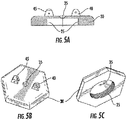
- FIG. 5 shows views of the cap 30 in both sectional ( FIG. 5A ) and perspective ( FIGS. 5B and 5C ) views.
- FIG. 5 illustrates merely a representative embodiment of a cap 30 that can be used in a handheld payload launcher system.
- the cap 30 is shown with its firing pin opening 35, the hinge 40 on the cap adapted to receive the hinge portion 55 of the firing pin (not shown) and which is secured to the cap hinge 40 by a hinge pin 43 (not shown).
- the closed top safety pin receptacle 45 on the cap adapted to receive the firing pin 50 and to retain the safety arm 60 of the firing pin.
- FIG. 5C illustrates the threads 25 that correspond to threads on the aft end of the launcher tube 10.
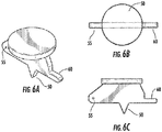
- FIG. 6 provides views of an embodiment of the firing pin of this disclosure.
- FIG. 6 illustrates a perspective view ( FIG. 6A ) and elevation views ( FIG. 6B and FIG. 6C ) of a representative aspect of a handheld payload launcher system, showing the firing pin 50 with its hinge portion 55 adapted to receive a hinge pin 43 (not shown) as it mates with the hinge 40 on the cap 50, its safety arm 60, adapted to fit under the closed top safety pin receptacle 45 on the cap and to be used with a safety pin 65 (not shown).
- FIG. 7 provides a sectional view of a representative aspect of a handheld payload launcher system 5 with its nozzle end 15 and aft end 20, and illustrating the launcher tube with a single chamber 70 adapted for use with a self-contained cartridge.
- the embodiment illustrated in FIG. 7 includes a nozzle receiving area 85 at the nozzle end 15 of the launcher tube 10, that is adapted for a choke or nozzle to be attached such as, for example, a threaded piece that is screwed into a threaded nozzle end.
- Use of a nozzle is optional in the launcher system, because there are applications for which very dispersed patterns are desired such that no focusing of the payload is desired.
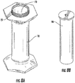
- FIG. 8 provides perspective views of a representative embodiment of a handheld payload launcher system 5 of this disclosure.
- the embodiment illustrated in FIG. 8A includes a single chamber 70 adapted for use with a self-contained cartridge 90 having a primer, a propellant and a payload, shown in FIG. 8B .
- Illustrated are launcher tube 10, the aft end 20, and threads 25 at the aft end adapted to receive the cap 10, such as shown in FIG. 5 , wherein the cap will be fitted with a firing pin, such as shown in FIG. 6 .
- the launcher embodiment of FIG. 8 illustrates the launcher tube with a single chamber 70 contrasts with the FIG. 1 embodiment that includes sub-chambers.
- FIG. 8 corresponds to the embodiment illustrated in FIG. 7 .
- a hinge on the cap 40 is provided that is adapted to receive the hinge portion of the firing pin 55 and a hinge pin 43 (not shown), which connects these two components.
- the firing pin 50 remains connected with the cap 30 and the firing pin can rotate relative to the cap about a fixed axis of rotation, through a small arc.
- the hinge has a very limited angle of rotation between the firing pin and the cap, due to the closed top safety pin receptacle 45 on the cap which limits and retains the safety arm 60 of the firing pin. While a rotatably connected firing pin is illustrated, any method of mounting the firing pin to the cap such that it is movably connected and securable to achieve the functions shown are envisioned.
- the payload launcher system includes a safety system comprising a safety pin 65 (not shown) that extends through the safety pin receptacle 45 on the cap 30 , and blocks the safety arm 60 of firing pin in its hinged orientation from forward motion, such that contact of the firing pin with the primer is prevented. Therefore, prior to use, the safety arm 60 is locked between the closed top of the safety pin receptacle 45 on the cap on aft side and the safety pin itself on the cap (forward) side, until such time the pin is removed.
- the safety pin 65 can be similar to that found on any common fire extinguisher that must be pulled out to "arm" the device.
- the disclosed launcher requires only a sharp "rap" with either some object or the heel of the free hand to fire.
- the firing pin (aft) end of the entire device can be slammed against a wall or other immovable surface, while holding the muzzle (fore) end pointing in the direction that payload is desired to be launched.
- This handheld manipulation is facilitated by the flared muzzle (fore) end and flared firing pin (aft) end, which allows striking the firing pin with or on any object with sufficient force to ignite the primer to launch the payload, while protecting the hand that is holding the launcher itself.
- the hand held launcher system of this disclosure can be provided with additional features or structures as desired, to take full advantage of its utility as a self-contained cartridge.
- the nozzle end 15 of the launcher tube 10 can provide the functions of a standard barrel from which a payload might conventionally be launched.
- the nozzle end 15 of the payload cartridge could contain, comprise, or could be made of a material that is shaped in a manner to form a nozzle or "choke" upon launching, which can force a particular or desired pattern of the ejected payload.
- the material used to construct the nozzle end portion of the cartridge itself could be selected according to thickness, shape, stiffness, composition, crimp structure, and the like, such that it conforms to a desired nozzle shape when opened during launching the payload. Therefore, there are multiple ways to provide the nozzle function when desired, including with the end portion of the cartridge itself, with the shape of the nozzle end 15 , or by way of an attached component such as a threaded piece that is attached at the nozzle receiving area 85, for example by being screwed into a threaded nozzle receiving area 85.
- the nozzle end 15 of launcher tube 10 can be designed to have a threaded tube inserted (not illustrated), made of a flexible material such as plastic or paper, in which the threaded tube can be crimped either with a "pie-type" crimp similar to the common shotshell crimp, or a roll crimp, which provides a method of sealing the tube to impart waterproof features.
- a threaded tube inserted (not illustrated), made of a flexible material such as plastic or paper, in which the threaded tube can be crimped either with a "pie-type" crimp similar to the common shotshell crimp, or a roll crimp, which provides a method of sealing the tube to impart waterproof features.
- Such a structure could have a significant taper inside the tube if needed. In this manner, a true nozzle or "choke” taper can be included in the final handheld launcher that is factory-loaded.
- This structure could serve to focus a stream of the payload such as a dry powder over a greater distance than is possible when simply launching it out of a "cylinder" bore with little or no taper.
- the specific features of this structure are a function of the desired performance parameters, such as the desired distance and dispersion of payload, all of which can be adjusted by the structure, material, crimp properties, and the like, as disclosed herein.
- the launcher system can comprise various propellant means of providing rapid forward movement, propulsion, or launching of the payload other than a standard propellant.
- propulsion means can include methods of providing rapidly expanding gas in the aft end of the launcher tube, a system of springs, a compressed gas source, and the like.
- propulsion can be provided by a compressed gas, such as would be available with a gas cylinder, including a CO 2 (carbon dioxide) cylinder or cartridge.
- a cartridge valve that meters a blast of gas can provide propulsion, or a gas cartridge that can be pierced by penetrating contact with a sharp piercing structure can provide a blast of propelling gas.
- Any variety of propulsion means to provide a launching mechanism are envisioned by this disclosure.
- a payload launcher system comprising:
- the payload launcher system can further comprise an adjustable or interchangeable nozzle that allows a desired payload pattern or spread to be selected.
- an adjustable or interchangeable nozzle that allows a desired payload pattern or spread to be selected.
- a shotgun-style choke system can be employed in which choke tubes can be used to focus the payload delivery as desired, and such tubes can be interchanged among those offering tight patterns, to those providing more wide spread patterns, to a continuous range of patterns in between the tight and wide spread patterns.
- the nozzle end of the launcher tube can include a nozzle receiving area as a means to attach and secure a choke or nozzle, such as threads, that have corresponding threads on the choke or interchangeable nozzle.
- a shotgun-style adjustable choke system can be used similarly that does not require interchanging chokes.
- the payload launcher system comprises a chamber that can be shaped to receiving any type of cartridge system, because regardless of the cartridge type, the launcher system includes the recoil mitigating feature and method of use.
- a self-contained cartridge comprising a primer, a payload, and an optional propellant beyond the primer itself can be used.
- multiple cartridge components can be used.
- the chamber of the launcher tube can comprise a first sub-chamber within the launcher tube adjacent the firing pin opening and a second sub-chamber within the launcher tube adjacent the first sub-chamber, the first sub-chamber shaped to receive a first self-contained cartridge comprising the primer, and the second sub-chamber shaped to receive a second self-contained cartridge comprising the payload.
- the first self-contained cartridge can further comprises a propellant adjacent the primer, if desired.
- the first self-contained cartridge can simply be a blank cartridge.
- Gas seals can be used as needed or desired between the propellant and the payload in any embodiment. Further the gas seal can be a preformed gas seal, or can comprise an obturating medium between the propellant and the payload, wherein the self-contained cartridge or cartridge components do not include a pre-shaped gas seal.
- this disclosure provides a payload launcher system, in which the system can comprise:
- this disclosure provides a method of using a payload launcher system, the method comprising:
- Still another aspect of this disclosure provides a method of launching a payload, the method comprising:
- the components of the launcher system of this disclosure can be fabricated from any suitable material that will resist the heat and pressure of launching, including any suitable plastic, metal, composite, polymer, or combination thereof.
- a suitable plastic or composite material may be used.
- the device is relatively light for carry by military troops, law enforcement and the like, it is expected that there will be only moderate recoil when the device is launched, because most payloads are expected to be launched with from below 100 fps (feet-per-second) muzzle velocities, to about 300 or 400 fps muzzle velocity. These velocities are all that is required, because it is expected that these devices will be most useful for launching payloads at close ranges, for example, from 15 to 40 feet in many cases.
- certain advantages of the disclosed handheld launcher include the ability of this design to pack and contain possibly reactive chemicals in a waterproof cartridge/launcher for safety.
- the launcher is specifically designed to deliver its payload at short range, with extremely high reliability, using a system that does not require constant maintenance or recharges to maintain pressure. It is also expected that it will be possible to minimize injury to personnel, should it be necessary to launch a chemical payload such as fire suppression chemicals or anti-chemical warfare substances, directly at personnel with the intent to cover the individual with the chemical payload.
- the present launcher system can be used to deliver any number of payload types, including but not limited to, rubber projectile payload, a bean bag payload, frangible payload, a tear gas-containing payload, an oleoresin capsicum-containing payload, a liquid-containing payload, a powder-containing payload, a gel-containing payload, a marking payload, a tracer payload, an incendiary payload, a flare payload, a chemical or chemical-containing payload, a biological or biological-containing payload, or any combination thereof.
- payload types including but not limited to, rubber projectile payload, a bean bag payload, frangible payload, a tear gas-containing payload, an oleoresin capsicum-containing payload, a liquid-containing payload, a powder-containing payload, a gel-containing payload, a marking payload, a tracer payload, an incendiary payload, a flare payload, a chemical or chemical-containing
- the launcher of this disclosure is not required to be hand held, and in some embodiments can be used in a fixed mount configuration for specific purposes.
- a mounted launcher can be fitted with a heat sensing activator that triggers the propulsion means (for example, a propellant, a compressed gas, or a spring system) in case of fire, thereby spraying an area with a fire suppressant material.
- the propulsion means for example, a propellant, a compressed gas, or a spring system
- Such a system employs a different trigger activating method that the hand held version which employs a striking blow of some type to the firing pin.
- the disclosed launcher does not fall under the definitions of "destructive device” as set forth in either Title I (the Gun Control Act of 1968) or Title II (the National Firearms Act of 1934) of the Federal firearms laws.
- the launcher devices cannot be used or fired with any known ammunition. Rather, primer and propellant cartridges must be specifically manufactured for use in these launcher systems, typically using a proprietary or non-standard size.
- the types of payloads and cartridges that the launcher is designed to handle are not anti-personnel payloads, but rather those designed for saving lives and property, such as various chemical payloads.
- the launcher systems of this disclosure can be used to launch cartridges that contain payloads such as dry chemicals, gels, and the like, examples of which include fire suppression chemicals, anti-chemical warfare substances that can counteract chemical warfare agents, or anti-biological warfare substances that can counteract biological warfare agents.
- payloads such as dry chemicals, gels, and the like, examples of which include fire suppression chemicals, anti-chemical warfare substances that can counteract chemical warfare agents, or anti-biological warfare substances that can counteract biological warfare agents.
- the present launcher system can be adapted to launch other payloads that may constitute classifying the device as a "destructive device", such as a non-frangible payload, a penetrator payload, a flechette payload, an armor-piercing payload, an explosive payload, and the like. Therefore, the present devices could be adapted for use with a grenade launcher cartridge, an explosive-launching cartridge, an armor-piercing cartridge, or anti-personnel cartridges.
- Reference to the nozzle end, forward end, or fore end of a particular launcher, component, or cartridge means the end that is further downrange when the component or cartridge is in its intended orientation for firing.
- the fore end may also be termed the leading end or leading edge, the top, the downrange end, or the distal end, and these terms are used interchangeably.
- Reference to the aft, rearward or rear end of a particular launcher, component, or cartridge means the end that is further uprange when the component or cartridge is in its intended orientation for firing.
- the rear end may also be termed trailing end or trailing edge, the aft portion or aft end, the bottom, the uprange end, the proximal end, or the primer end, and these terms are used interchangeably.
- a projectile or “a payload” includes a single projectile such as a slug made of the desired material, as well as any combination of more than one projectile, such as multiple pellets of the material in any size or combination of sizes.
- reference to “a payload” includes multiple particles of a chemical composition or mixture of compositions that constitutes a projectile in that it is launched at a target.
- the word “comprise” and variations of the word, such as “comprising” and “comprises,” means “including but not limited to,” and is not intended to exclude, for example, other additives, components, elements, or steps. While structures, compositions, and methods are described in terms of “comprising” various components or steps, the structures, compositions, and methods can also “consist essentially of” or “consist of” the various components or steps.
- Values or ranges may be expressed herein as “about”, from “about” one particular value, and/or to “about” another particular value. When such values or ranges are expressed, other embodiments disclosed include the specific value recited, from the one particular value, and/or to the other particular value. Similarly, when values are expressed as approximations, by use of the antecedent "about,” it will be understood that the particular value forms another embodiment. It will be further understood that there are a number of values disclosed herein, and that each value is also herein disclosed as “about” that particular value in addition to the value itself.
Landscapes
- Engineering & Computer Science (AREA)
- General Engineering & Computer Science (AREA)
- Toys (AREA)
- Medicines Containing Antibodies Or Antigens For Use As Internal Diagnostic Agents (AREA)
Applications Claiming Priority (2)
| Application Number | Priority Date | Filing Date | Title |
|---|---|---|---|
| US201161515097P | 2011-08-04 | 2011-08-04 | |
| EP12748313.9A EP2739932A2 (de) | 2011-08-04 | 2012-08-03 | Tragbares nutzlastträgersystem |
Related Parent Applications (1)
| Application Number | Title | Priority Date | Filing Date |
|---|---|---|---|
| EP12748313.9A Division EP2739932A2 (de) | 2011-08-04 | 2012-08-03 | Tragbares nutzlastträgersystem |
Publications (1)
| Publication Number | Publication Date |
|---|---|
| EP3258206A1 true EP3258206A1 (de) | 2017-12-20 |
Family
ID=46690711
Family Applications (2)
| Application Number | Title | Priority Date | Filing Date |
|---|---|---|---|
| EP17153642.8A Withdrawn EP3258206A1 (de) | 2011-08-04 | 2012-08-03 | Tragbares nutzlastträgersystem |
| EP12748313.9A Withdrawn EP2739932A2 (de) | 2011-08-04 | 2012-08-03 | Tragbares nutzlastträgersystem |
Family Applications After (1)
| Application Number | Title | Priority Date | Filing Date |
|---|---|---|---|
| EP12748313.9A Withdrawn EP2739932A2 (de) | 2011-08-04 | 2012-08-03 | Tragbares nutzlastträgersystem |
Country Status (3)
| Country | Link |
|---|---|
| US (1) | US9383161B2 (de) |
| EP (2) | EP3258206A1 (de) |
| WO (1) | WO2013020025A2 (de) |
Families Citing this family (1)
| Publication number | Priority date | Publication date | Assignee | Title |
|---|---|---|---|---|
| US10054410B2 (en) * | 2011-08-04 | 2018-08-21 | James Y. Menefee, III | Cartridge for handheld payload launcher system |
Citations (11)
| Publication number | Priority date | Publication date | Assignee | Title |
|---|---|---|---|---|
| DE365573C (de) * | 1922-01-02 | 1922-12-18 | Fritz Kuchen | Viehschussapparat |
| US2880543A (en) * | 1956-06-26 | 1959-04-07 | Hercules Gas Munitions Corp | Pistol |
| US4083138A (en) * | 1976-12-13 | 1978-04-11 | Charles Cash | Close combat backup weapon |
| FR2377018A1 (fr) * | 1977-01-06 | 1978-08-04 | Pains Wessex Ltd | Artifice pyrotechnique manipulable |
| US4268987A (en) * | 1979-08-29 | 1981-05-26 | Charles Cash | Hand weapon for survival purposes |
| DE29707924U1 (de) * | 1996-05-09 | 1997-07-24 | Diefke Wadie-Munition - GmbH & Co KG, 97653 Bischofsheim | Reizstoffpatrone |
| US5783768A (en) * | 1996-02-08 | 1998-07-21 | Quoin, Inc. | Fire starting flare |
| US20070006506A1 (en) * | 2005-07-08 | 2007-01-11 | Mey-Chu Lan | Liquid filling bullet for physical protection |
| US7814820B2 (en) | 2005-11-17 | 2010-10-19 | Jay Menefee | Method and apparatus for manufacturing wad-less ammunition |
| US20110017090A1 (en) | 2005-11-17 | 2011-01-27 | Menefee Iii James Y | Wad-less cartridges and method of manufacturing the same |
| WO2011085751A1 (de) * | 2009-12-22 | 2011-07-21 | Diehl Bgt Defence Gmbh & Co. Kg | Handgranatenzünder |
Family Cites Families (85)
| Publication number | Priority date | Publication date | Assignee | Title |
|---|---|---|---|---|
| US985171A (en) * | 1910-02-16 | 1911-02-28 | Krupp Ag | Pull mechanism for guns. |
| US1565036A (en) | 1921-03-02 | 1925-12-08 | Tank Henry | Fire-extinguishing grenade |
| US1788443A (en) * | 1929-04-13 | 1931-01-13 | Reginald F Sedgley | Firearm |
| US2042934A (en) * | 1933-09-29 | 1936-06-02 | Newton S Hillyard | Firearm |
| NL41344C (de) | 1935-03-18 | 1900-01-01 | ||
| US2444920A (en) * | 1947-01-13 | 1948-07-13 | Jr George B Davis | Firing mechanism |
| US2519123A (en) * | 1947-07-10 | 1950-08-15 | Dwyer Martin | Hand-operated rocket type device for signaling and other purposes |
| US2651972A (en) | 1949-10-31 | 1953-09-15 | Edmund H Engelke | Stop shoulder for recoilless rifle ammunition |
| US2541025A (en) | 1950-01-25 | 1951-02-13 | Guion S Bluford | Artillery ammunition training round |
| US2789471A (en) | 1951-02-07 | 1957-04-23 | Guion S Bluford | Lightweight recoilless artillery weapon |
| US2889653A (en) * | 1952-07-29 | 1959-06-09 | Kilgore Inc | Firing mechanism |
| US3008412A (en) | 1956-10-09 | 1961-11-14 | William A Merdinyan | Cartridge case for a recoilless rifle |
| US2889747A (en) | 1956-10-30 | 1959-06-09 | Ewald A Kamp | Recoilless gun for separate loading ammunition |
| US2970519A (en) | 1958-11-26 | 1961-02-07 | Musser C Walton | Recoilless rifle |
| US2970520A (en) | 1959-07-10 | 1961-02-07 | Andrew J Grandy | Recoilless rifle breech |
| US3026775A (en) | 1959-07-13 | 1962-03-27 | Musser C Walton | Recoilless rifle with a vena contracta orifice |
| US2949061A (en) | 1959-08-03 | 1960-08-16 | Benditt Albert | Recoilless rifle with expanding nozzle |
| US3027809A (en) | 1960-01-22 | 1962-04-03 | Musser C Walton | Recoilless rifle |
| US3008378A (en) | 1960-04-28 | 1961-11-14 | Musser C Walton | Powder grain baffle for recoilless rifle |
| US3188956A (en) * | 1961-10-09 | 1965-06-15 | Hellis Stuart Clifford | Shot gun cartridge |
| US3144808A (en) | 1962-09-11 | 1964-08-18 | Walter B Stapp | Recoilless rifle firing mechanism |
| US3352238A (en) * | 1965-10-12 | 1967-11-14 | Universal Match Corp | Atomizer and method for disseminating toxicants |
| US3443333A (en) * | 1967-08-04 | 1969-05-13 | Andrew E Manatos | Tear gas palm pistol |
| US3575113A (en) | 1968-02-26 | 1971-04-13 | Ashbrook Clifford L | Progressive burn shell |
| NL137093C (de) * | 1968-07-08 | |||
| US3630151A (en) * | 1969-10-27 | 1971-12-28 | Singer Co | Manually actuated fluidic igniter |
| US3611935A (en) * | 1969-10-31 | 1971-10-12 | Us Navy | Small caliber dual colored signal flare |
| US3721194A (en) | 1970-04-13 | 1973-03-20 | C Weston | Diversifying the shooting characteristics of shotguns |
| US3855930A (en) * | 1970-09-02 | 1974-12-24 | Mb Ass | Personnel distress signal |
| US3728809A (en) * | 1970-10-02 | 1973-04-24 | Mbass | Projectile launcher baton |
| US3705552A (en) * | 1971-02-08 | 1972-12-12 | Us Army | Pyrotechnic coiled delay cord assembly for hand grenade fuze |
| US3960052A (en) | 1972-11-17 | 1976-06-01 | Smith Matthew S | Weapon arrangement |
| US4010688A (en) | 1972-11-17 | 1977-03-08 | Smith Matthew S | Weapon arrangement |
| US3931726A (en) * | 1975-01-21 | 1976-01-13 | Amp Incorporated | Propellant-driven device for crimping large size wire and terminals |
| US3980139A (en) | 1975-09-15 | 1976-09-14 | Norman Kirk | Fire extinguishing bomb for putting out fires |
| US4192236A (en) * | 1976-03-04 | 1980-03-11 | Wallop Industries Limited | Firing mechanism for percussion caps |
| US4091709A (en) | 1976-07-26 | 1978-05-30 | The United States Of America As Represented By The Secretary Of The Army | Recoilless rifle nozzle |
| US4141275A (en) | 1977-07-14 | 1979-02-27 | The United States Of America As Represented By The Secretary Of The Navy | Afterburner recoilless rifle |
| US4411086A (en) * | 1981-03-16 | 1983-10-25 | Christopherson John K | Hand held, single shot, firearm |
| DE3111081A1 (de) | 1981-03-20 | 1982-09-30 | J.G. Anschütz GmbH, 7900 Ulm | "wettkampfschusswaffe, insbesondere gewehr oder pistole" |
| US4457233A (en) | 1982-09-29 | 1984-07-03 | Marshall Hyde | Aerial bomb |
| GB8325617D0 (en) | 1983-09-24 | 1983-10-26 | Taylor H F | Air guns |
| US4553481A (en) * | 1984-04-11 | 1985-11-19 | Vero Ricci | Shot gun shell tracer wad |
| DE3424597C1 (de) | 1984-07-04 | 1986-01-09 | Messerschmitt-Bölkow-Blohm GmbH, 8012 Ottobrunn | Anordnung zum Abbremsen eines Treibspiegels |
| US4644930A (en) * | 1984-07-18 | 1987-02-24 | Robert Mainhardt | Gun for firing a variety of projectiles |
| US4682952A (en) | 1985-09-27 | 1987-07-28 | Honeywell Inc. | Training device |
| US4689912A (en) * | 1986-06-26 | 1987-09-01 | Weapon Technology System R & D Ltd. | Hand-held high-velocity grenade launcher |
| US4964469A (en) | 1988-05-18 | 1990-10-23 | Smith Wayne D | Device for broadcasting dry material by explosive force |
| US5105569A (en) * | 1990-04-03 | 1992-04-21 | Richard A. Straitiff | Single shot pistol |
| US5085147A (en) * | 1990-10-01 | 1992-02-04 | Gold Robert J | Distraction device |
| CN1061658A (zh) | 1990-11-20 | 1992-06-03 | 潘登 | 通用无后坐力枪族 |
| US5171934A (en) * | 1990-12-24 | 1992-12-15 | Larry Moore | Shortened shotshell with double-cupped wadding |
| US5233774A (en) * | 1991-01-10 | 1993-08-10 | Joel Leibowitz | Baton gun |
| BE1007314A3 (fr) | 1993-07-16 | 1995-05-16 | Browning Sa Societe Anonyme | Arme a feu perfectionnee. |
| US5413050A (en) * | 1993-08-18 | 1995-05-09 | Maki; Nagatoshi | Pattern controller used with shotshell |
| US5388361A (en) * | 1994-03-22 | 1995-02-14 | James E. Alexander | Nightstick with shell-firing mechanism |
| FR2721394B1 (fr) | 1994-06-16 | 1996-08-09 | France Etat Armement | Dispositif de mise à feu d'une charge pyrotechnique du type bouchon allumeur notamment pour grenade à main ayant trois modes de fonctionnement. |
| DE19500477C1 (de) | 1994-08-08 | 1995-11-23 | Amrona Ag | Verfahren und Vorrichtung zum Löschen von Bränden |
| US5631441A (en) * | 1996-04-02 | 1997-05-20 | Her Majesty The Queen In Right Of Canada, As Represented By The Minister Of National Defence Of Her Majesty's Canadian Government | XDM pyrophoric countermeasure flare |
| US6060289A (en) | 1996-07-26 | 2000-05-09 | Ajinomoto Co., Inc. | Modified bacterial cellulose |
| RU2103627C1 (ru) | 1996-08-16 | 1998-01-27 | Владимир Валентинович Волков | Безоткатное орудие |
| US6393992B1 (en) | 1996-11-18 | 2002-05-28 | Jaycor Tactical Systems, Inc. | Non-lethal projectile for delivering an inhibiting substance to a living target |
| SE511197C2 (sv) | 1997-06-05 | 1999-08-23 | Simbal Ab | Övningsvapensystem för ett buret rekylfritt pansarvärnsvapen med räfflat eldrör |
| US6131515A (en) | 1997-12-11 | 2000-10-17 | Remington Arms Company, Inc. | Electric primer |
| US5937556A (en) * | 1998-02-17 | 1999-08-17 | Daily; Timothy M. | Mechanism and method for firing caps |
| US6012531A (en) | 1998-04-20 | 2000-01-11 | Ryan; James W. | Fire extinguishing bomb |
| US6164209A (en) * | 1998-12-21 | 2000-12-26 | Olin Corporation | Shotshell basewad |
| US6860187B2 (en) | 1999-04-07 | 2005-03-01 | Metal Storm Limited | Projectile launching apparatus and methods for fire fighting |
| US6283037B1 (en) * | 1999-12-20 | 2001-09-04 | Procopio J. Sclafani | Non-lethal shot-gun round |
| FR2807511B1 (fr) * | 2000-04-06 | 2003-01-24 | Lacroix Soc E | Verrou pour levier de bouchon allumeur |
| CA2408944A1 (en) | 2000-05-18 | 2001-11-22 | Paul C. Edwards | Fire retardant delivery system |
| RU2170405C1 (ru) | 2000-07-10 | 2001-07-10 | Открытое акционерное общество "Тульский оружейный завод" | Безоткатное орудие для стрельбы управляемыми снарядами |
| US6470805B1 (en) | 2001-04-30 | 2002-10-29 | The United States Of America As Represented By The Secretary Of The Navy | Fire retardant bio-friendly practice munition |
| US7025001B2 (en) * | 2002-10-21 | 2006-04-11 | Combined Systems, Inc. | Super long range crash-bang round |
| US20060075671A1 (en) | 2004-10-08 | 2006-04-13 | Grimes Paul J | Firearm for extinguishing a fire from a position remote from the fire |
| US7478680B2 (en) | 2005-01-24 | 2009-01-20 | Vinayagamurthy Sridharan | Fire extinguishing by explosive pulverisation of projectile based frozen gases and compacted solid extinguishing agents |
| RO122108B1 (ro) | 2005-03-22 | 2008-12-30 | Vasile Cînciu | Pat de armă de vânătoare fără recul |
| US20070012213A1 (en) * | 2005-07-12 | 2007-01-18 | Sheaffer Clifford G | Shot pattern control wad structure for shotshell |
| US7415929B1 (en) * | 2006-02-01 | 2008-08-26 | The United States Of America As Represented By The Secretary Of The Army | Systems with bore-launched projectiles |
| DE102007003180B4 (de) * | 2007-01-22 | 2009-01-08 | Heckler & Koch Gmbh | Waffe mit Rückstoßdämpfung |
| WO2009039221A2 (en) * | 2007-09-18 | 2009-03-26 | Pepperball Technologies, Inc. | Systems, methods and apparatus for use in distributing irritant powder |
| US8061274B1 (en) * | 2009-01-26 | 2011-11-22 | Brejon Holdings (BVI), Ltd. | Less than lethal projectile and a method for producing the same |
| ES2688660T3 (es) | 2010-05-11 | 2018-11-06 | Saab Ab | Sistema de arma de entrenamiento para fusiles antitanque sin retroceso |
| EP2739930B1 (de) * | 2011-08-04 | 2016-10-12 | Polywad, Inc. | Rückstossabgeschwächtes nutzlastträgersystem |
| US20130042783A1 (en) * | 2011-08-16 | 2013-02-21 | Wendell Diller | Shotgun Tracer |
-
2012
- 2012-08-03 US US13/566,200 patent/US9383161B2/en active Active
- 2012-08-03 EP EP17153642.8A patent/EP3258206A1/de not_active Withdrawn
- 2012-08-03 EP EP12748313.9A patent/EP2739932A2/de not_active Withdrawn
- 2012-08-03 WO PCT/US2012/049471 patent/WO2013020025A2/en not_active Ceased
Patent Citations (11)
| Publication number | Priority date | Publication date | Assignee | Title |
|---|---|---|---|---|
| DE365573C (de) * | 1922-01-02 | 1922-12-18 | Fritz Kuchen | Viehschussapparat |
| US2880543A (en) * | 1956-06-26 | 1959-04-07 | Hercules Gas Munitions Corp | Pistol |
| US4083138A (en) * | 1976-12-13 | 1978-04-11 | Charles Cash | Close combat backup weapon |
| FR2377018A1 (fr) * | 1977-01-06 | 1978-08-04 | Pains Wessex Ltd | Artifice pyrotechnique manipulable |
| US4268987A (en) * | 1979-08-29 | 1981-05-26 | Charles Cash | Hand weapon for survival purposes |
| US5783768A (en) * | 1996-02-08 | 1998-07-21 | Quoin, Inc. | Fire starting flare |
| DE29707924U1 (de) * | 1996-05-09 | 1997-07-24 | Diefke Wadie-Munition - GmbH & Co KG, 97653 Bischofsheim | Reizstoffpatrone |
| US20070006506A1 (en) * | 2005-07-08 | 2007-01-11 | Mey-Chu Lan | Liquid filling bullet for physical protection |
| US7814820B2 (en) | 2005-11-17 | 2010-10-19 | Jay Menefee | Method and apparatus for manufacturing wad-less ammunition |
| US20110017090A1 (en) | 2005-11-17 | 2011-01-27 | Menefee Iii James Y | Wad-less cartridges and method of manufacturing the same |
| WO2011085751A1 (de) * | 2009-12-22 | 2011-07-21 | Diehl Bgt Defence Gmbh & Co. Kg | Handgranatenzünder |
Also Published As
| Publication number | Publication date |
|---|---|
| US9383161B2 (en) | 2016-07-05 |
| US20130031819A1 (en) | 2013-02-07 |
| WO2013020025A2 (en) | 2013-02-07 |
| EP2739932A2 (de) | 2014-06-11 |
| WO2013020025A3 (en) | 2013-08-15 |
Similar Documents
| Publication | Publication Date | Title |
|---|---|---|
| US10054410B2 (en) | Cartridge for handheld payload launcher system | |
| US6688032B1 (en) | Rifle-launched non-lethal cargo dispenser | |
| US8701325B1 (en) | Duplex weapon system | |
| US9453713B1 (en) | Systems and methods for ammunition for a disrupter cannon | |
| US5529300A (en) | Self-powered extensible projectile launching police baton | |
| US9322625B1 (en) | Systems and methods for launching water from a disrupter cannon | |
| US20030106545A1 (en) | Non-lethal handgun | |
| US8484876B2 (en) | Firearms for launching electrified projectiles | |
| US20060011090A1 (en) | Primer launched projectile systems | |
| US5983772A (en) | Subcaliber device/blank firing adaptor for blowback or recoil operated weapons | |
| US20070181029A1 (en) | Method and apparatus for propelling a pellet or BB using a shock-sensitive explosive cap | |
| US6647890B2 (en) | Self-contained round having ring airfoil projectile and launcher therefor | |
| US3706151A (en) | Gun and projectile for shooting fluids | |
| US20240035788A1 (en) | Low lethal projectile system | |
| US11333468B2 (en) | Shot shell with projectile | |
| US20070151551A1 (en) | Non-lethal hand pistol | |
| US8807004B1 (en) | Recoil attenuated payload launcher system | |
| US20020144446A1 (en) | Combination device to launch non-lethal projectiles using a detachable, disposable container | |
| KR20180100165A (ko) | 비치사적 무력 장치 | |
| US8516729B2 (en) | Reduced lethality gun | |
| US9383161B2 (en) | Handheld payload launcher system | |
| US9103613B2 (en) | Multiple cartridge assembly for less than lethal cartridge | |
| US20220178663A1 (en) | Enhanced Projectile for Modern Pneumatic Sporting Devices /Air Rifles | |
| RU2353896C2 (ru) | Дымовая граната | |
| RU2602867C2 (ru) | Пневматическое оружие самообороны, клинок и метаемые элементы |
Legal Events
| Date | Code | Title | Description |
|---|---|---|---|
| PUAI | Public reference made under article 153(3) epc to a published international application that has entered the european phase |
Free format text: ORIGINAL CODE: 0009012 |
|
| STAA | Information on the status of an ep patent application or granted ep patent |
Free format text: STATUS: THE APPLICATION HAS BEEN PUBLISHED |
|
| AC | Divisional application: reference to earlier application |
Ref document number: 2739932 Country of ref document: EP Kind code of ref document: P |
|
| AK | Designated contracting states |
Kind code of ref document: A1 Designated state(s): AL AT BE BG CH CY CZ DE DK EE ES FI FR GB GR HR HU IE IS IT LI LT LU LV MC MK MT NL NO PL PT RO RS SE SI SK SM TR |
|
| STAA | Information on the status of an ep patent application or granted ep patent |
Free format text: STATUS: REQUEST FOR EXAMINATION WAS MADE |
|
| 17P | Request for examination filed |
Effective date: 20180620 |
|
| RBV | Designated contracting states (corrected) |
Designated state(s): AL AT BE BG CH CY CZ DE DK EE ES FI FR GB GR HR HU IE IS IT LI LT LU LV MC MK MT NL NO PL PT RO RS SE SI SK SM TR |
|
| STAA | Information on the status of an ep patent application or granted ep patent |
Free format text: STATUS: THE APPLICATION IS DEEMED TO BE WITHDRAWN |
|
| 18D | Application deemed to be withdrawn |
Effective date: 20210302 |