EP3258207A1 - Système de mesure de structures d'un objet à mesurer - Google Patents
Système de mesure de structures d'un objet à mesurer Download PDFInfo
- Publication number
- EP3258207A1 EP3258207A1 EP17174332.1A EP17174332A EP3258207A1 EP 3258207 A1 EP3258207 A1 EP 3258207A1 EP 17174332 A EP17174332 A EP 17174332A EP 3258207 A1 EP3258207 A1 EP 3258207A1
- Authority
- EP
- European Patent Office
- Prior art keywords
- measuring
- measuring arrangement
- arrangement according
- digital microscope
- electronic ruler
- Prior art date
- Legal status (The legal status is an assumption and is not a legal conclusion. Google has not performed a legal analysis and makes no representation as to the accuracy of the status listed.)
- Granted
Links
Images
Classifications
-
- G—PHYSICS
- G01—MEASURING; TESTING
- G01B—MEASURING LENGTH, THICKNESS OR SIMILAR LINEAR DIMENSIONS; MEASURING ANGLES; MEASURING AREAS; MEASURING IRREGULARITIES OF SURFACES OR CONTOURS
- G01B3/00—Measuring instruments characterised by the use of mechanical techniques
- G01B3/02—Rulers with scales or marks for direct reading
- G01B3/04—Rulers with scales or marks for direct reading rigid
-
- G—PHYSICS
- G01—MEASURING; TESTING
- G01B—MEASURING LENGTH, THICKNESS OR SIMILAR LINEAR DIMENSIONS; MEASURING ANGLES; MEASURING AREAS; MEASURING IRREGULARITIES OF SURFACES OR CONTOURS
- G01B11/00—Measuring arrangements characterised by the use of optical techniques
- G01B11/02—Measuring arrangements characterised by the use of optical techniques for measuring length, width or thickness
- G01B11/028—Measuring arrangements characterised by the use of optical techniques for measuring length, width or thickness by measuring lateral position of a boundary of the object
-
- G—PHYSICS
- G01—MEASURING; TESTING
- G01B—MEASURING LENGTH, THICKNESS OR SIMILAR LINEAR DIMENSIONS; MEASURING ANGLES; MEASURING AREAS; MEASURING IRREGULARITIES OF SURFACES OR CONTOURS
- G01B11/00—Measuring arrangements characterised by the use of optical techniques
- G01B11/14—Measuring arrangements characterised by the use of optical techniques for measuring distance or clearance between spaced objects or spaced apertures
-
- G—PHYSICS
- G02—OPTICS
- G02B—OPTICAL ELEMENTS, SYSTEMS OR APPARATUS
- G02B21/00—Microscopes
- G02B21/36—Microscopes arranged for photographic purposes or projection purposes or digital imaging or video purposes including associated control and data processing arrangements
-
- G—PHYSICS
- G02—OPTICS
- G02B—OPTICAL ELEMENTS, SYSTEMS OR APPARATUS
- G02B21/00—Microscopes
- G02B21/36—Microscopes arranged for photographic purposes or projection purposes or digital imaging or video purposes including associated control and data processing arrangements
- G02B21/368—Microscopes arranged for photographic purposes or projection purposes or digital imaging or video purposes including associated control and data processing arrangements details of associated display arrangements, e.g. mounting of LCD monitor
Definitions
- the invention relates to a measuring arrangement for measuring the geometry of structures of a measurement object, for example distances between structures of the measurement object.
- geometrical sizes of the products for example distances between structures on one surface of the products, must be precisely measured throughout the entire production of the products, for example during development, production and final inspection.
- a measuring arrangement which can be used for this purpose must have high accuracy, process capability and robustness.
- the measuring arrangement should be able to measure a multiplicity of structures of a measuring object, for example distances between edges, graphic elements, embossings, slits, engravings etc.
- the measurement should be carried out independently of a substrate on which the structures are arranged with high accuracy.
- the measuring arrangement should be capable of being able to measure structures on different carrier materials, such as, for example, paper, films, textiles, stamped sheets, etc.
- An object of the present invention is to provide a measuring arrangement with which it is possible to measure structures of a measuring object with high accuracy.
- the measuring arrangement comprises an electronic ruler with a measuring carriage and a digital microscope, which is attached to the measuring carriage of the electronic ruler.
- the measuring arrangement is designed such that the digital microscope is displaced together with the measuring carriage during a displacement of the measuring slide.
- the digital microscope is aligned over the DUT.
- the digital microscope can be aligned, for example, over an edge of a structure of the measurement object. If necessary, an image of the edge can be enlarged on a screen of the digital microscope.
- a display on a display device of the measuring carriage can be switched to a zero position.
- the digital microscope is now moved to a further structure of the measurement object, for example a further edge of an adjacent structure on the surface of the measurement object.
- the distance between the edges of the two structures can be read.
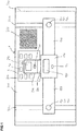
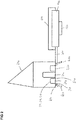
- FIGS. 1 and 2 show a measuring arrangement 1 for digitally measuring distances between structures of a measuring object 10.
- the measuring objects 10 are, for example, labels which are glued on a label sheet 2.
- the measuring arrangement 1 is shown in FIG. 1 in a plan view and in FIG FIG. 2 shown in a side view.
- the measuring arrangement 1 comprises an electronic / digital ruler 100 with a measuring carriage 110 and a digital microscope 200.
- the digital microscope 200 is attached to the measuring carriage 110 of the electronic ruler 100 in such a way that it is moved when the measuring carriage 110 moves.
- the measuring carriage 110 is displaceably arranged along a rail 150 of the electronic ruler 100 in the longitudinal direction of the rail 150.
- the digital microscope 200 can be fastened to the measuring slide 110 of the electronic ruler 100, for example, by means of a holding element 500.
- the holding member 500 is fixed on one side to the measuring carriage 110 of the electronic ruler 100.
- the digital microscope 200 is attached on the other side of the holding element 500.
- the holding element 500 may be formed, for example, as a thin sheet.
- the holding member 500 may have a recess 510 at the end to which the digital microscope 200 is attached.
- a fixing element 600 for fixing the digital microscope 200 to the holding element 500, a fixing element 600, for example in the form of a nut made of a transparent material, can be used.
- the fixing element 600 has, for example, an internal thread 610, on which an external thread 260 of the digital microscope can be fastened, in order thus to securely fix the digital microscope 200 to the holding element 500.
- the electronic ruler 100 has a fastening device 120 for fastening the measuring arrangement 1 on a substrate.
- the fastening device 120 may have, for example, at least one magnet 121. This makes it possible to fix the measuring arrangement 1 from the electronic ruler 100 and the digital microscope 200 to a metallic substrate, for example to a metallic housing of a machine, with the aid of the at least one magnet 121.
- any other suitable fastening devices for fixing the measuring arrangement 1 on a substrate can be used.
- the fastening device 120 may, for example, have at least one suction foot 122. By means of the at least one suction foot 122, it is possible to secure the measuring arrangement 1, in particular the electronic ruler 100, to a substrate by generating a vacuum.
- a fastening device 120 for example a magnet 121 or a suction foot 122, is provided on the underside of the electronic ruler 100 at opposite end sections.
- the fastening device 120 may be formed in a simple embodiment, for example, as a weight for weighting the measuring arrangement 1.
- the electronic ruler 100 may have a display device 130 for digitally displaying a measured value and an operating device 140 for resetting the measured value to a zero position.
- the electronic ruler 100 is in particular designed such that the measured value displayed on the display device 130 changes starting from the zero position as a function of a movement of the measuring carriage 110.
- the displayed measured value indicates, for example, a distance between structures of a DUT.
- the measurement carriage 110 is first moved in such a way that the digital microscope 200 is aligned with an edge of a first structure. In this position, the measured value displayed on the display device 130 is reset by the operating device 140 to the zero position. Subsequently, the measuring carriage 110 is moved such that the digital microscope 200 is aligned with the edge of a second structure of the measurement object. The travel path of the measuring carriage, which corresponds to a distance between the edge of the first and the edge of the second structure of the measuring object, is displayed on the display device 130 of the measuring carriage 110.
- the digital microscope 200 includes a camera 230 for capturing an image of the measurement object 120 and a screen 240 for displaying the captured image of the measurement object.
- the camera can be switched on by means of a control element 260.
- the camera 230 may be equipped with a zoom / magnify function for zooming in / out a portion of the measurement object 10 in an image displayed on the screen 240. This makes it possible to enlarge structures, for example edges of a pattern, which is printed on a surface of the measurement object.
- the enlarged area of the measuring object 10 is displayed on the screen 240 of the digital microscope 200.
- the digital microscope 200 can be precisely aligned with a structural element, for example an edge of a structure, of the measurement object.
- the magnification of the image can be set, for example, on the operating element 260.
- the digital microscope 200 may be designed such that in the image on the screen 240 of the microscope 200, a marker 250 for aligning the digital microscope is superimposed on a structure of the measurement object.
- the marker 250 may be a frame or a cross that is displayed on the screen 240 in the image of the measurement object.
- the digital microscope can be aligned with a structure of the measurement object. This is done, for example, by aligning the marker 250 with an edge of a structure.
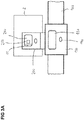
- the marker 250 in the form of a frame is in the FIGS. 3A and 3B shown.
- the digital microscope 200 may have a lighting device 210 for illuminating the measuring object 10.
- the illumination device 210 may include, for example, at least one light source 211 for generating white light and / or at least one light source 212 for generating ultraviolet light and / or at least one light source 213 for generating infrared light.
- the light source / light sources can be turned on at the operating element 260.
- the light source 211 for generating white light can be switched on in order to illuminate the structure.
- a Light source 212 for generating ultraviolet light and / or a light source 213 for generating infrared light it is possible to visually detect and analyze UV / IR-active substances on the measurement object, for example in the printed image of a label.
- luminescence surfaces on the surface of a measurement object can be geometrically measured.
- the digital microscope 200 comprises a heating source 220 for heating the measuring object.
- the heating source 220 integrated in the digital microscope 200 for example, various elements can be made visible by thermal action on a material surface of a measurement object. These include, for example, structures of thermoreactive colors. These structures are not visible to the naked eye, but may be visualized by heating by the heating source 220 and displayed on the screen 240 of the digital microscope 200.
- the measuring arrangement 1 comprises a worktop 300 for placing the measuring object 10 and for arranging the electronic ruler 100 on the worktop 300.
- the electronic ruler 100 can be fixed on the worktop 300, for example by means of the fastening device 120.
- the functional working plate 300 may be formed magnetically, for example as a metallic worktop. If the at least one magnet 121 is provided on the underside of the electronic ruler 100 as the fastening device 120, the electronic ruler 100 can be securely fastened on the magnetic working plate 300, so that slippage of the electronic ruler is prevented.
- the measurement arrangement 1 can have a cover 400 for covering the measurement object on the work surface 300.
- the cover 400 is transparent, so that the measurement object is visible through the cover 400.
- the cover 400 may, for example, be formed as a transparent thin film or a transparent pane, for example a pane of Plexiglas.
- the measurement object can be placed between the transparent cover 400 and the work surface 300 on the work surface.
- the fastener 600 rests on the cover 400.
- the Cover 400 provides protection against damage to the surface of the DUT.
- the measurement objects labels 10 which are adhered to the label sheet 2.
- the sheet is disposed on the countertop 300 between the cover 400 and the surface of the countertop 300.
- the measuring objects usually have a different color or can also be transparent.
- An example of transparent measurement objects are films that are printed with structures.
- the work surface 300 can comprise different regions 310, 320, which each have a different coloring or structuring.
- the surface of the area 320 of the work surface 300 is colored gray.
- measuring objects with a white carrier substrate for example labels with a white carrier substrate which is printed with a color
- a transparent support for example a transparent film which is printed with a structure
- guide rails 330a and 330b may be provided on the sides of the work surface 300, into which the electronic ruler may be inserted.
- the electronic ruler may have attached to its underside projecting elements with which the ruler 100 is inserted into the guide rails.
- the electronic ruler on the work plate 300 can be shifted up or down.
- another way to vertically / horizontally orient the ruler 100 is to use an elbow that can be applied to one side of the edge of the work surface 300 and on the other side of which the ruler 100 can be placed and aligned.
- the measuring object 10 is for example a label which is applied together with further labels on a label sheet 2.
- a user can first hang the label sheet 2 on the countertop 300.
- the label sheet is placed between the surface of the work surface 300 and the transparent cover 400.
- the measuring arrangement 1 from the measuring ruler 100 and the digital microscope 200 is then placed on the work surface 300 or the transparent cover 400.
- the fastening device 120 for example the magnets 121 arranged on the underside of the electronic ruler 100, the measuring object 10 between the working plate 300 and the cover 400 is securely fixed.
- a distance between edges 11, 12 of structures of the measuring object 10 is to be measured.
- the electronic ruler 100 and the digital microscope 200 are switched on at the operating device 140 or the operating element 260.
- the measuring carriage 110 is then moved so far until an edge 11 of a structure of the measurement object in the image, which is displayed on the screen 240, is visible.
- one of the light sources 211, 212, 213 or the heat source 220 on the control element 260 is turned on.
- the measuring carriage 110 is moved until the marker 250 is congruent over the edge 11 of a structure to be measured.
- the marker 250 is designed as a frame whose side line is aligned with the measuring edge 11 of a structure of the measurement object.
- the measured value currently displayed on the display device 130 is reset to a zero position by actuating the operating device 140.
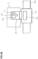
- a user can now move the measuring carriage 110 to a second measuring edge 12 of the structure of the measuring object, which in FIG. 3B is displayed, move.
- a fine alignment of the digital microscope 200 can also be carried out at the second measuring edge 12 until the marker 250, for example a lateral line of the digital microscope 200 Frame on the screen 240 is congruent with the second measuring edge 12 of the measurement object.
- the measured value now displayed on the display device 130 corresponds to the distance between the first measuring edge 11 and the second measuring edge 12 of the measuring object.
- distances between structures of a test object can be measured with high precision. It can be a variety of structures, such as distances between edges, graphic elements, embossing, slotting, engraving and much more on different substrates, such as paper, films, textiles, stamping plates, etc. are measured.
- a measurement object can be optimally illuminated.
- UV / IR active substances can be made visible by illumination with the UV light source 212 and the IR light source 213, respectively. If the measurement object has thermo-reactive features to be investigated, these structures can be visualized by means of the heating source 220 integrated in the digital microscope 200.
- the measurement object By fixing the measurement object between the work surface 300 and the cover 400, the measurement object can on the one hand be securely fixed and, on the other hand, damage to the material surface of the measurement object when viewed through the digital microscope can be avoided.
Landscapes
- Physics & Mathematics (AREA)
- General Physics & Mathematics (AREA)
- Engineering & Computer Science (AREA)
- Multimedia (AREA)
- Chemical & Material Sciences (AREA)
- Analytical Chemistry (AREA)
- Optics & Photonics (AREA)
- Length Measuring Devices By Optical Means (AREA)
Applications Claiming Priority (1)
| Application Number | Priority Date | Filing Date | Title |
|---|---|---|---|
| DE102016110956.8A DE102016110956A1 (de) | 2016-06-15 | 2016-06-15 | Messanordnung zum Vermessen von Strukturen eines Messobjekts |
Publications (2)
| Publication Number | Publication Date |
|---|---|
| EP3258207A1 true EP3258207A1 (fr) | 2017-12-20 |
| EP3258207B1 EP3258207B1 (fr) | 2021-08-04 |
Family
ID=59009580
Family Applications (1)
| Application Number | Title | Priority Date | Filing Date |
|---|---|---|---|
| EP17174332.1A Active EP3258207B1 (fr) | 2016-06-15 | 2017-06-02 | Système de mesure de structures d'un objet à mesurer |
Country Status (2)
| Country | Link |
|---|---|
| EP (1) | EP3258207B1 (fr) |
| DE (1) | DE102016110956A1 (fr) |
Citations (4)
| Publication number | Priority date | Publication date | Assignee | Title |
|---|---|---|---|---|
| US4596037A (en) * | 1984-03-09 | 1986-06-17 | International Business Machines Corporation | Video measuring system for defining location orthogonally |
| US4667231A (en) * | 1979-09-07 | 1987-05-19 | Diffracto Ltd. | Electro-optical part inspection in the presence of contamination and surface finish variation |
| US4916535A (en) * | 1987-06-17 | 1990-04-10 | Volodchenko Dmitry B | Method of non-destructive quality inspection of materials and videomonitor realizing this method |
| WO2001073374A1 (fr) * | 2000-03-27 | 2001-10-04 | Buechler Roman | Microscope de mesure |
Family Cites Families (3)
| Publication number | Priority date | Publication date | Assignee | Title |
|---|---|---|---|---|
| DE1001008B (de) * | 1956-02-23 | 1957-01-17 | Zeiss Jena Veb Carl | Laengenmessmaschine |
| CH399751A (de) * | 1960-09-23 | 1965-09-30 | Hensoldt & Soehne Optik | Gerät zur Anzeige der Verschiebungsgrösse eines Schlittens in einer Maschine |
| DD62851A1 (da) * | 1967-06-24 | 1968-07-20 | Karl-Hans Vollrath | Vorrichtung zum messen des abstandes zwischen gummituch-oder druckformoberfläche und schmitzringoberfläche |
-
2016
- 2016-06-15 DE DE102016110956.8A patent/DE102016110956A1/de active Pending
-
2017
- 2017-06-02 EP EP17174332.1A patent/EP3258207B1/fr active Active
Patent Citations (4)
| Publication number | Priority date | Publication date | Assignee | Title |
|---|---|---|---|---|
| US4667231A (en) * | 1979-09-07 | 1987-05-19 | Diffracto Ltd. | Electro-optical part inspection in the presence of contamination and surface finish variation |
| US4596037A (en) * | 1984-03-09 | 1986-06-17 | International Business Machines Corporation | Video measuring system for defining location orthogonally |
| US4916535A (en) * | 1987-06-17 | 1990-04-10 | Volodchenko Dmitry B | Method of non-destructive quality inspection of materials and videomonitor realizing this method |
| WO2001073374A1 (fr) * | 2000-03-27 | 2001-10-04 | Buechler Roman | Microscope de mesure |
Non-Patent Citations (1)
| Title |
|---|
| MARTIN ERLEKAMM: "Instructions, -ibidi heating system", 7 May 2008 (2008-05-07), XP055395987, Retrieved from the Internet <URL:http://ibidi.com/img/cms/products/instruments/I_109XX_HeatingSystem/IN_1091X_heating_system_Minitube.pdf> [retrieved on 20170803] * |
Also Published As
| Publication number | Publication date |
|---|---|
| DE102016110956A1 (de) | 2017-12-21 |
| EP3258207B1 (fr) | 2021-08-04 |
Similar Documents
| Publication | Publication Date | Title |
|---|---|---|
| EP3606709B1 (fr) | Découpeuse avec caméra de vision générale | |
| DE102006015792A1 (de) | Verfahren und System zur Formmessung einer reflektierenden Oberfläche | |
| DE102014005281B4 (de) | Bestimmung der Position zumindest eines Brillenglases im Raum | |
| DE102017112976B4 (de) | Verfahren zum Kalibrieren einer optischen Anordnung eines Koordinatenmessgerätes | |
| EP1481218B1 (fr) | Dispositif et procede de mesure des geometries d'objets essentiellement bidimensionnels | |
| DE102007010223B4 (de) | Verfahren zur Bestimmung geometrischer Parameter eines Wafers und Verwendung des Verfahren bei der optischen Inspektion von Wafern | |
| DE29618623U1 (de) | Vorrichtung zum Kultivieren von Mikroorganismen | |
| EP2063230A3 (fr) | Dispositif optique de mesure de la position | |
| DE102009032210A1 (de) | Bearbeitungsanlage | |
| AT16584U1 (de) | Bildaufnahmesystem und Qualitätskontrollstation mit Bildaufnahmesystem | |
| DE3635654C2 (fr) | ||
| DE3004888A1 (de) | Verfahren zur positionierung von filmen auf unterlagen sowie eine maschine hierzu | |
| DE19927025B4 (de) | Anordnung zur Erfassung der Oberflächenstrukturen von Fingern und/oder Handinnenflächen | |
| DE102012214280A1 (de) | Dokumentenlesegerät mit einer Dokumentenauflage | |
| EP3258207B1 (fr) | Système de mesure de structures d'un objet à mesurer | |
| DE102017102320A1 (de) | Bearbeitungsanlage | |
| WO2021037328A1 (fr) | Procédé et dispositif d'alignement de substrats | |
| DE102011008513B4 (de) | Einstell- und/oder Messgerätevorrichtung | |
| EP2974865B1 (fr) | Procede de determination de localisation de defaut sur un substrat d'impression et dispositif pour realiser cette procede | |
| DE8524880U1 (de) | Sehschärfe-Testplatte | |
| DE102007010807B4 (de) | Verfahren und Vorrichtung zur Vermessung der Topografie einer Oberfläche eines Messobjekts | |
| DE102007036815A1 (de) | Koordinaten-Messmaschine und Verfahren zur Bestimmung der lateralen Korrektur in Abhängigkeit von der Substrattopologie | |
| DE102010013164A1 (de) | Zum Platzieren eines Bauteils auf einem Substrat geeignete Vorrichtung sowie ein solches Verfahren | |
| DE102013218404A1 (de) | Optoelektronisches Bauelement und Verfahren zu seiner Herstellung | |
| DE102004036819A1 (de) | Verfahren zur Bestimmung der Bestückgenauigkeit eines Bestückautomaten, optisches Messsystem |
Legal Events
| Date | Code | Title | Description |
|---|---|---|---|
| PUAI | Public reference made under article 153(3) epc to a published international application that has entered the european phase |
Free format text: ORIGINAL CODE: 0009012 |
|
| STAA | Information on the status of an ep patent application or granted ep patent |
Free format text: STATUS: THE APPLICATION HAS BEEN PUBLISHED |
|
| AK | Designated contracting states |
Kind code of ref document: A1 Designated state(s): AL AT BE BG CH CY CZ DE DK EE ES FI FR GB GR HR HU IE IS IT LI LT LU LV MC MK MT NL NO PL PT RO RS SE SI SK SM TR |
|
| AX | Request for extension of the european patent |
Extension state: BA ME |
|
| STAA | Information on the status of an ep patent application or granted ep patent |
Free format text: STATUS: REQUEST FOR EXAMINATION WAS MADE |
|
| 17P | Request for examination filed |
Effective date: 20180620 |
|
| RBV | Designated contracting states (corrected) |
Designated state(s): AL AT BE BG CH CY CZ DE DK EE ES FI FR GB GR HR HU IE IS IT LI LT LU LV MC MK MT NL NO PL PT RO RS SE SI SK SM TR |
|
| STAA | Information on the status of an ep patent application or granted ep patent |
Free format text: STATUS: EXAMINATION IS IN PROGRESS |
|
| 17Q | First examination report despatched |
Effective date: 20190809 |
|
| GRAP | Despatch of communication of intention to grant a patent |
Free format text: ORIGINAL CODE: EPIDOSNIGR1 |
|
| STAA | Information on the status of an ep patent application or granted ep patent |
Free format text: STATUS: GRANT OF PATENT IS INTENDED |
|
| INTG | Intention to grant announced |
Effective date: 20210112 |
|
| GRAS | Grant fee paid |
Free format text: ORIGINAL CODE: EPIDOSNIGR3 |
|
| GRAA | (expected) grant |
Free format text: ORIGINAL CODE: 0009210 |
|
| STAA | Information on the status of an ep patent application or granted ep patent |
Free format text: STATUS: THE PATENT HAS BEEN GRANTED |
|
| AK | Designated contracting states |
Kind code of ref document: B1 Designated state(s): AL AT BE BG CH CY CZ DE DK EE ES FI FR GB GR HR HU IE IS IT LI LT LU LV MC MK MT NL NO PL PT RO RS SE SI SK SM TR |
|
| REG | Reference to a national code |
Ref country code: GB Ref legal event code: FG4D Free format text: NOT ENGLISH |
|
| REG | Reference to a national code |
Ref country code: AT Ref legal event code: REF Ref document number: 1417392 Country of ref document: AT Kind code of ref document: T Effective date: 20210815 |
|
| REG | Reference to a national code |
Ref country code: CH Ref legal event code: EP |
|
| REG | Reference to a national code |
Ref country code: DE Ref legal event code: R096 Ref document number: 502017011073 Country of ref document: DE |
|
| REG | Reference to a national code |
Ref country code: IE Ref legal event code: FG4D Free format text: LANGUAGE OF EP DOCUMENT: GERMAN |
|
| REG | Reference to a national code |
Ref country code: LT Ref legal event code: MG9D |
|
| REG | Reference to a national code |
Ref country code: NL Ref legal event code: MP Effective date: 20210804 |
|
| PG25 | Lapsed in a contracting state [announced via postgrant information from national office to epo] |
Ref country code: RS Free format text: LAPSE BECAUSE OF FAILURE TO SUBMIT A TRANSLATION OF THE DESCRIPTION OR TO PAY THE FEE WITHIN THE PRESCRIBED TIME-LIMIT Effective date: 20210804 Ref country code: SE Free format text: LAPSE BECAUSE OF FAILURE TO SUBMIT A TRANSLATION OF THE DESCRIPTION OR TO PAY THE FEE WITHIN THE PRESCRIBED TIME-LIMIT Effective date: 20210804 Ref country code: PT Free format text: LAPSE BECAUSE OF FAILURE TO SUBMIT A TRANSLATION OF THE DESCRIPTION OR TO PAY THE FEE WITHIN THE PRESCRIBED TIME-LIMIT Effective date: 20211206 Ref country code: NO Free format text: LAPSE BECAUSE OF FAILURE TO SUBMIT A TRANSLATION OF THE DESCRIPTION OR TO PAY THE FEE WITHIN THE PRESCRIBED TIME-LIMIT Effective date: 20211104 Ref country code: HR Free format text: LAPSE BECAUSE OF FAILURE TO SUBMIT A TRANSLATION OF THE DESCRIPTION OR TO PAY THE FEE WITHIN THE PRESCRIBED TIME-LIMIT Effective date: 20210804 Ref country code: ES Free format text: LAPSE BECAUSE OF FAILURE TO SUBMIT A TRANSLATION OF THE DESCRIPTION OR TO PAY THE FEE WITHIN THE PRESCRIBED TIME-LIMIT Effective date: 20210804 Ref country code: FI Free format text: LAPSE BECAUSE OF FAILURE TO SUBMIT A TRANSLATION OF THE DESCRIPTION OR TO PAY THE FEE WITHIN THE PRESCRIBED TIME-LIMIT Effective date: 20210804 Ref country code: BG Free format text: LAPSE BECAUSE OF FAILURE TO SUBMIT A TRANSLATION OF THE DESCRIPTION OR TO PAY THE FEE WITHIN THE PRESCRIBED TIME-LIMIT Effective date: 20211104 Ref country code: LT Free format text: LAPSE BECAUSE OF FAILURE TO SUBMIT A TRANSLATION OF THE DESCRIPTION OR TO PAY THE FEE WITHIN THE PRESCRIBED TIME-LIMIT Effective date: 20210804 |
|
| PG25 | Lapsed in a contracting state [announced via postgrant information from national office to epo] |
Ref country code: PL Free format text: LAPSE BECAUSE OF FAILURE TO SUBMIT A TRANSLATION OF THE DESCRIPTION OR TO PAY THE FEE WITHIN THE PRESCRIBED TIME-LIMIT Effective date: 20210804 Ref country code: LV Free format text: LAPSE BECAUSE OF FAILURE TO SUBMIT A TRANSLATION OF THE DESCRIPTION OR TO PAY THE FEE WITHIN THE PRESCRIBED TIME-LIMIT Effective date: 20210804 Ref country code: GR Free format text: LAPSE BECAUSE OF FAILURE TO SUBMIT A TRANSLATION OF THE DESCRIPTION OR TO PAY THE FEE WITHIN THE PRESCRIBED TIME-LIMIT Effective date: 20211105 |
|
| PG25 | Lapsed in a contracting state [announced via postgrant information from national office to epo] |
Ref country code: NL Free format text: LAPSE BECAUSE OF FAILURE TO SUBMIT A TRANSLATION OF THE DESCRIPTION OR TO PAY THE FEE WITHIN THE PRESCRIBED TIME-LIMIT Effective date: 20210804 |
|
| PG25 | Lapsed in a contracting state [announced via postgrant information from national office to epo] |
Ref country code: DK Free format text: LAPSE BECAUSE OF FAILURE TO SUBMIT A TRANSLATION OF THE DESCRIPTION OR TO PAY THE FEE WITHIN THE PRESCRIBED TIME-LIMIT Effective date: 20210804 |
|
| REG | Reference to a national code |
Ref country code: DE Ref legal event code: R097 Ref document number: 502017011073 Country of ref document: DE |
|
| PG25 | Lapsed in a contracting state [announced via postgrant information from national office to epo] |
Ref country code: SM Free format text: LAPSE BECAUSE OF FAILURE TO SUBMIT A TRANSLATION OF THE DESCRIPTION OR TO PAY THE FEE WITHIN THE PRESCRIBED TIME-LIMIT Effective date: 20210804 Ref country code: SK Free format text: LAPSE BECAUSE OF FAILURE TO SUBMIT A TRANSLATION OF THE DESCRIPTION OR TO PAY THE FEE WITHIN THE PRESCRIBED TIME-LIMIT Effective date: 20210804 Ref country code: RO Free format text: LAPSE BECAUSE OF FAILURE TO SUBMIT A TRANSLATION OF THE DESCRIPTION OR TO PAY THE FEE WITHIN THE PRESCRIBED TIME-LIMIT Effective date: 20210804 Ref country code: EE Free format text: LAPSE BECAUSE OF FAILURE TO SUBMIT A TRANSLATION OF THE DESCRIPTION OR TO PAY THE FEE WITHIN THE PRESCRIBED TIME-LIMIT Effective date: 20210804 Ref country code: CZ Free format text: LAPSE BECAUSE OF FAILURE TO SUBMIT A TRANSLATION OF THE DESCRIPTION OR TO PAY THE FEE WITHIN THE PRESCRIBED TIME-LIMIT Effective date: 20210804 Ref country code: AL Free format text: LAPSE BECAUSE OF FAILURE TO SUBMIT A TRANSLATION OF THE DESCRIPTION OR TO PAY THE FEE WITHIN THE PRESCRIBED TIME-LIMIT Effective date: 20210804 |
|
| PLBE | No opposition filed within time limit |
Free format text: ORIGINAL CODE: 0009261 |
|
| STAA | Information on the status of an ep patent application or granted ep patent |
Free format text: STATUS: NO OPPOSITION FILED WITHIN TIME LIMIT |
|
| 26N | No opposition filed |
Effective date: 20220506 |
|
| PG25 | Lapsed in a contracting state [announced via postgrant information from national office to epo] |
Ref country code: IT Free format text: LAPSE BECAUSE OF FAILURE TO SUBMIT A TRANSLATION OF THE DESCRIPTION OR TO PAY THE FEE WITHIN THE PRESCRIBED TIME-LIMIT Effective date: 20210804 |
|
| PG25 | Lapsed in a contracting state [announced via postgrant information from national office to epo] |
Ref country code: SI Free format text: LAPSE BECAUSE OF FAILURE TO SUBMIT A TRANSLATION OF THE DESCRIPTION OR TO PAY THE FEE WITHIN THE PRESCRIBED TIME-LIMIT Effective date: 20210804 |
|
| PG25 | Lapsed in a contracting state [announced via postgrant information from national office to epo] |
Ref country code: MC Free format text: LAPSE BECAUSE OF FAILURE TO SUBMIT A TRANSLATION OF THE DESCRIPTION OR TO PAY THE FEE WITHIN THE PRESCRIBED TIME-LIMIT Effective date: 20210804 |
|
| REG | Reference to a national code |
Ref country code: CH Ref legal event code: PL |
|
| REG | Reference to a national code |
Ref country code: BE Ref legal event code: MM Effective date: 20220630 |
|
| GBPC | Gb: european patent ceased through non-payment of renewal fee |
Effective date: 20220602 |
|
| PG25 | Lapsed in a contracting state [announced via postgrant information from national office to epo] |
Ref country code: LU Free format text: LAPSE BECAUSE OF NON-PAYMENT OF DUE FEES Effective date: 20220602 Ref country code: LI Free format text: LAPSE BECAUSE OF NON-PAYMENT OF DUE FEES Effective date: 20220630 Ref country code: IE Free format text: LAPSE BECAUSE OF NON-PAYMENT OF DUE FEES Effective date: 20220602 Ref country code: FR Free format text: LAPSE BECAUSE OF NON-PAYMENT OF DUE FEES Effective date: 20220630 Ref country code: CH Free format text: LAPSE BECAUSE OF NON-PAYMENT OF DUE FEES Effective date: 20220630 |
|
| PG25 | Lapsed in a contracting state [announced via postgrant information from national office to epo] |
Ref country code: GB Free format text: LAPSE BECAUSE OF NON-PAYMENT OF DUE FEES Effective date: 20220602 Ref country code: BE Free format text: LAPSE BECAUSE OF NON-PAYMENT OF DUE FEES Effective date: 20220630 |
|
| REG | Reference to a national code |
Ref country code: AT Ref legal event code: MM01 Ref document number: 1417392 Country of ref document: AT Kind code of ref document: T Effective date: 20220602 |
|
| PG25 | Lapsed in a contracting state [announced via postgrant information from national office to epo] |
Ref country code: AT Free format text: LAPSE BECAUSE OF NON-PAYMENT OF DUE FEES Effective date: 20220602 |
|
| PG25 | Lapsed in a contracting state [announced via postgrant information from national office to epo] |
Ref country code: HU Free format text: LAPSE BECAUSE OF FAILURE TO SUBMIT A TRANSLATION OF THE DESCRIPTION OR TO PAY THE FEE WITHIN THE PRESCRIBED TIME-LIMIT; INVALID AB INITIO Effective date: 20170602 |
|
| PG25 | Lapsed in a contracting state [announced via postgrant information from national office to epo] |
Ref country code: MK Free format text: LAPSE BECAUSE OF FAILURE TO SUBMIT A TRANSLATION OF THE DESCRIPTION OR TO PAY THE FEE WITHIN THE PRESCRIBED TIME-LIMIT Effective date: 20210804 Ref country code: CY Free format text: LAPSE BECAUSE OF FAILURE TO SUBMIT A TRANSLATION OF THE DESCRIPTION OR TO PAY THE FEE WITHIN THE PRESCRIBED TIME-LIMIT Effective date: 20210804 |
|
| PG25 | Lapsed in a contracting state [announced via postgrant information from national office to epo] |
Ref country code: TR Free format text: LAPSE BECAUSE OF FAILURE TO SUBMIT A TRANSLATION OF THE DESCRIPTION OR TO PAY THE FEE WITHIN THE PRESCRIBED TIME-LIMIT Effective date: 20210804 |
|
| PG25 | Lapsed in a contracting state [announced via postgrant information from national office to epo] |
Ref country code: MT Free format text: LAPSE BECAUSE OF FAILURE TO SUBMIT A TRANSLATION OF THE DESCRIPTION OR TO PAY THE FEE WITHIN THE PRESCRIBED TIME-LIMIT Effective date: 20210804 |
|
| PGFP | Annual fee paid to national office [announced via postgrant information from national office to epo] |
Ref country code: DE Payment date: 20260624 Year of fee payment: 10 |