EP3258224B1 - Ecarteur destine a conserver un ecart entre un conducteur interne en forme de tige et un conducteur externe d'une sonde de mesure de niveau de remplissage - Google Patents
Ecarteur destine a conserver un ecart entre un conducteur interne en forme de tige et un conducteur externe d'une sonde de mesure de niveau de remplissage Download PDFInfo
- Publication number
- EP3258224B1 EP3258224B1 EP16174228.3A EP16174228A EP3258224B1 EP 3258224 B1 EP3258224 B1 EP 3258224B1 EP 16174228 A EP16174228 A EP 16174228A EP 3258224 B1 EP3258224 B1 EP 3258224B1
- Authority
- EP
- European Patent Office
- Prior art keywords
- rod
- spacer
- shaped inner
- inner conductor
- support elements
- Prior art date
- Legal status (The legal status is an assumption and is not a legal conclusion. Google has not performed a legal analysis and makes no representation as to the accuracy of the status listed.)
- Active
Links
Images



Classifications
-
- G—PHYSICS
- G01—MEASURING; TESTING
- G01F—MEASURING VOLUME, VOLUME FLOW, MASS FLOW OR LIQUID LEVEL; METERING BY VOLUME
- G01F23/00—Indicating or measuring liquid level or level of fluent solid material, e.g. indicating in terms of volume or indicating by means of an alarm
- G01F23/0046—Indicating or measuring liquid level or level of fluent solid material, e.g. indicating in terms of volume or indicating by means of an alarm with a stationary probe, where a liquid specimen is separated from the mean mass and measured
-
- G—PHYSICS
- G01—MEASURING; TESTING
- G01B—MEASURING LENGTH, THICKNESS OR SIMILAR LINEAR DIMENSIONS; MEASURING ANGLES; MEASURING AREAS; MEASURING IRREGULARITIES OF SURFACES OR CONTOURS
- G01B5/00—Measuring arrangements characterised by the use of mechanical techniques
- G01B5/02—Measuring arrangements characterised by the use of mechanical techniques for measuring length, width or thickness
- G01B5/06—Measuring arrangements characterised by the use of mechanical techniques for measuring length, width or thickness for measuring thickness
- G01B5/061—Measuring arrangements characterised by the use of mechanical techniques for measuring length, width or thickness for measuring thickness height gauges
-
- G—PHYSICS
- G01—MEASURING; TESTING
- G01F—MEASURING VOLUME, VOLUME FLOW, MASS FLOW OR LIQUID LEVEL; METERING BY VOLUME
- G01F23/00—Indicating or measuring liquid level or level of fluent solid material, e.g. indicating in terms of volume or indicating by means of an alarm
- G01F23/22—Indicating or measuring liquid level or level of fluent solid material, e.g. indicating in terms of volume or indicating by means of an alarm by measuring physical variables, other than linear dimensions, pressure or weight, dependent on the level to be measured, e.g. by difference of heat transfer of steam or water
- G01F23/28—Indicating or measuring liquid level or level of fluent solid material, e.g. indicating in terms of volume or indicating by means of an alarm by measuring physical variables, other than linear dimensions, pressure or weight, dependent on the level to be measured, e.g. by difference of heat transfer of steam or water by measuring the variations of parameters of electromagnetic or acoustic waves applied directly to the liquid or fluent solid material
- G01F23/284—Electromagnetic waves
-
- B—PERFORMING OPERATIONS; TRANSPORTING
- B25—HAND TOOLS; PORTABLE POWER-DRIVEN TOOLS; MANIPULATORS
- B25B—TOOLS OR BENCH DEVICES NOT OTHERWISE PROVIDED FOR, FOR FASTENING, CONNECTING, DISENGAGING, OR HOLDING
- B25B27/00—Hand tools, specially adapted for fitting together or separating parts or objects whether or not involving some deformation, not otherwise provided for
- B25B27/02—Hand tools, specially adapted for fitting together or separating parts or objects whether or not involving some deformation, not otherwise provided for for connecting objects by press fit or detaching same
- B25B27/06—Hand tools, specially adapted for fitting together or separating parts or objects whether or not involving some deformation, not otherwise provided for for connecting objects by press fit or detaching same inserting or withdrawing sleeves or bearing races
-
- H—ELECTRICITY
- H01—ELECTRIC ELEMENTS
- H01P—WAVEGUIDES; RESONATORS, LINES, OR OTHER DEVICES OF THE WAVEGUIDE TYPE
- H01P3/00—Waveguides; Transmission lines of the waveguide type
- H01P3/02—Waveguides; Transmission lines of the waveguide type with two longitudinal conductors
- H01P3/06—Coaxial lines
Definitions
- the present invention relates to a spacer for maintaining a distance between a rod-shaped inner conductor and an outer conductor of a level measuring probe.
- the invention also relates to a rod-shaped inner conductor of a measuring probe, a measuring probe for determining a fill level of a medium located in a container, and an assembly method for assembling a spacer on a rod-shaped inner conductor.
- Time domain reflectometry which is also known as Time Domain Reflectometry (TDR) is used to determine and analyze run lengths and reflection characteristics of electromagnetic waves and signals.
- TDR Time Domain Reflectometry
- an electromagnetic pulse is generated by the electronics of the sensor, coupled into a conductor, which is also referred to as a measuring probe, and guided along this probe.
- a conductor which is also referred to as a measuring probe
- coaxial measuring probes are used in which a rod-shaped inner conductor CGS: PSU
- the electromagnetic pulse After the electromagnetic pulse has been coupled into the measuring probe, it is now reflected on the surface of the medium to be measured and runs back along the measuring probe to an electronics unit, which then calculates the level from the time difference between the transmitted and received pulse.
- Such a measuring probe can be exposed to vibrations or external shocks, so that this can result in inaccuracies in the measurement.
- the DE 10 2011 009 385 A1 describes a spacer for centering an inner conductor in an outer conductor of a coaxial conductor.
- An outer ring resting on the inner wall of the outer conductor is provided as a support structure, with at least two ring segments spaced around the circumference of the inner rod being provided to form a central opening, which are connected to the outer ring via spoke-like webs.
- the US 6,380,750 B1 describes a measuring probe in which a spacer is provided for spacing an outer conductor from an inner conductor.
- the spacer surrounds the outer conductor in the assembled state.
- spacer elements are provided on the inner surface of the ring segment of the spacer.
- a spacer for maintaining a distance between a rod-shaped inner conductor and an outer conductor of a level measuring probe has an annular element and at least three support elements which each protrude in a radial direction from an inner surface of the annular element.
- Each of the three support elements has a curved end face at an end facing away from the inner face. The end facing away from the inner surface is designed to engage in a recess in the rod-shaped inner conductor.
- a coaxial measuring probe which is also referred to below as a fill level measuring probe or simply as a measuring probe.
- the suitability of such measuring probes can be improved in systems with vibration loads. For example, when measuring the level, vibration loads or external shocks can occur, which can impair the measurement result.
- the spacer makes it possible to reduce the relative movement between the rod-shaped inner conductor and the outer conductor of the measuring probe even in the event of vibration loads. At the same time, electrical deviations in the measurement signal per spacer can be kept low.
- HF interference signals that is to say high-frequency interference signals, can be reduced compared to conventional connecting means for connecting the rod-shaped inner conductor and the outer conductor.
- the annular element has, for example, the shape of a tubular segment.
- the annular element can be a thin-walled tubular segment, for example in the form of a thin-walled cylinder.
- the ring-shaped element can have the shape of a section of a cylinder jacket.
- the ring-shaped element has a cylindrical inner surface and a cylindrical outer surface.
- the three support elements protrude from the cylindrical inner surface in the radial direction to a center point of the annular element.
- the respective support elements can be arranged along a circumferential direction of the annular element at regular intervals from one another on the inner surface. For example, the angle between each support element, in particular between the radial directions of the support elements, with respect to the circumferential direction of the annular element is 120 °.
- the three support elements each have an end facing away from the inner surface.
- the curved end face which is, for example, a simply curved surface.
- a single curved surface means that the surface is curved only in one direction and has no curvature in a further direction.
- the curved end face can, for example, be a segment of a cylinder jacket surface.
- Each of the three support elements can furthermore have an end facing the inner surface, at which the respective support element is fastened to the inner surface of the annular element. Between this end facing the inner surface and the inner surface itself, a radius can be provided as a transition from the inner surface to the respective support element.
- the spacer can have a flexible or elastic material, so that the spacer can be positioned on the rod-shaped inner conductor with the aid of an assembly tool and then the outer conductor can be placed over the spacer.
- the end of the support elements facing away from the inner surface is designed to engage in a recess of the rod-shaped inner conductor.
- the rod-shaped inner conductor also has three recesses for this purpose, which correspond to the respective support element of the spacer, so that the end of the respective support element facing away from the inner surface can engage in the corresponding recess of the rod-shaped inner conductor.
- the radius of the curved end face of the end facing away from the inner surface differs from a radius of a surface of the rod-shaped inner conductor.
- the radius of the curved end face can match the radius of the surface of the rod-shaped inner conductor while the spacer is positioned on the rod-shaped inner conductor. This aspect will be explained in more detail below and in the description of the figures.
- the at least three support elements taper in the radial direction.
- the radial direction represents, for example, a central axis of the respective support element.
- the radial direction is a radial direction in relation to the annular element, that is, the radial direction runs through the center of the annular element.
- the cross-sectional area of the support element perpendicular to the radial direction at an end facing the inner surface of the annular element is larger than a cross-sectional area of the support element at the end of the support element remote from the inner surface.
- the at least three support elements can have a circular or oval cross-sectional area.
- the shape of the cross-sectional area of the respective support element can change in the radial direction.
- the cross-sectional area at an end facing the inner surface of the annular element can have an oval shape, the cross-sectional area of the end facing away from the inner surface having a circular shape.
- the at least three support elements are arranged at regular intervals along a circumferential direction of the annular element.
- the circumferential direction denotes that direction which extends along the cylindrical inner surface or the cylindrical outer surface of the annular element.
- the support elements can each be arranged at equal distances from one another on the inner surface of the annular element.
- An angle of 120 ° can be provided between the respective support elements.
- a correspondingly smaller angle can be provided between the individual support elements, the support elements in turn being arranged at equal intervals along the circumferential direction on the inner surface of the annular element. In this way, a uniform force transmission between the rod-shaped inner conductor and the outer conductor of the measuring probe can be achieved in the event of a vibration load.
- the support elements can be guided past a surface of the rod-shaped inner conductor during the assembly of the spacer on the rod-shaped inner conductor. This will be explained in more detail in the further course of the description.
- the curved end face of the respective support element has a radius, the center of which does not lie on an axis of rotation of the annular element or of the spacer.
- the radius of the curved end face can be chosen so that when the spacer or the annular element is deformed during assembly, optimal guidability of the curved end faces of the support elements over a surface of the rod-shaped inner conductor is ensured.
- the curved end faces of the support elements can be shifted, for example by 0.3 mm each, with respect to the center point of the annular element.
- the curved end faces are moved away from the center.
- the curved end faces or the bearing surfaces of the support elements are accordingly designed in such a way that the deformation path for pushing onto the rod-shaped Inner conductor is as small as possible during assembly in order to avoid damage to the spacer when expanding.
- the radius of the curved end face corresponds to the radius of the surface of the rod-shaped inner conductor.
- the radius of the curved end face during the deformation, i.e. during the assembly of the spacer on the rod-shaped inner conductor corresponds to the radius of the surface of the rod-shaped inner conductor, but the center point of the radius of the curved end face lies before or after assembly, that is in the relaxed state of the spacer, not on the axis of rotation of the annular element.
- the curved end face is designed to ensure optimal guidance of the spacer over the surface of the rod-shaped element during assembly.
- the at least three support elements each have a bore.
- the bore axes of the bores running through the support elements are each arranged inclined with respect to an axis of rotation of the annular element.
- the axis of rotation of the ring-shaped element in turn runs through the center of the ring-shaped element.
- Inclined bores are thus provided in the respective support elements, the bores being designed to receive a pin element of an assembly tool.
- the bore axes of the respective support elements can be inclined by about 0 ° to 20 °, preferably by about 0 ° to 10 ° and in particular by about 2.5 °, with respect to the axis of rotation of the annular element.
- the bores of the respective support elements can run through a central axis of the support elements which, for example, lies in the radial direction of the respective support elements.
- the respective bore axes of the bores running through the support elements intersect at a common point which lies on the axis of rotation of the annular element.
- all the bore axes of the support elements have the same inclination with respect to the axis of rotation of the annular element.
- This inclination is predetermined by the alignment of the pin elements of an assembly tool to be received through the bores.
- it is possible to expand or pretension the spacer by the pin elements of the assembly tool to be received, in order thus to mount the spacer on the rod-shaped inner conductor.
- the annular element has a cylindrical outer surface.
- the spacer is made from a plastic material.
- the spacer is possible for the spacer to be made from polyetheretherketone (PEEK).
- PEEK polyetheretherketone
- Such a material can ensure high strength over a wide temperature range, and such a material is also chemically resistant. This is particularly advantageous because the spacer can come into contact with the respective medium to be measured when measuring the fill level.
- a rod-shaped inner conductor of a measuring probe is specified.
- the rod-shaped inner conductor has a first row with at least three recesses along a circumferential direction of the rod-shaped inner conductor for receiving a support element of a spacer, in particular the spacer described above.
- the recesses each have a curved base area with a radius, the center of which does not lie on an axis of rotation of the rod-shaped inner conductor.
- the recesses are provided as blind holes.
- the recesses in the form of depressions in the surface of the rod-shaped inner conductor can be provided on a surface of the rod-shaped inner conductor.
- the recesses can be provided in the form of bores in the rod-shaped inner conductor, the base of the recesses assuming a simply curved shape.
- simply curved base area means that the base area is bent along one direction, for example along a circumferential direction of the rod-shaped inner conductor, and has no curvature along a further direction, which is, for example, parallel to the axis of rotation of the rod-shaped inner conductor.
- the curved base of the recess has the same curvature as the curved end face on the end of the support element of the spacer facing away from the inner surface.
- the end facing away from the inner surface in particular the curved end face of the support element of the spacer, can rest on the curved base surface of the rod-shaped inner conductor.
- the depressions that is to say the recesses, are formed in the rod-shaped inner conductor for optimal support with the same radius as the curved end face of the support elements of the spacer.
- the curved base of the recess is simply curved.
- An axis of rotation of the simply curved base surface of the recess and the axis of rotation of the rod-shaped inner conductor are spaced apart from one another.
- the curved base of the recesses is adapted to the curved end face of the support elements of the spacer.
- each curved base surface has a radius, the center of which lies on its own axis of rotation, the axes of rotation of the curved base surfaces of each recess being spaced from one another.
- the rod-shaped inner conductor also has a second row with at least three recesses along a circumferential direction of the rod-shaped inner conductor for receiving a support element of a spacer, in particular the spacer described above.
- the second row with the at least three recesses and the first row with the at least three recesses are spaced apart from one another along the axis of rotation of the rod-shaped inner conductor. Further rows with at least three recesses in the rod-shaped inner conductor are also possible.
- spacers can thus be provided on the rod-shaped inner conductor.
- exactly two spacers are provided between the rod-shaped inner conductor and the outer conductor in order to improve the vibration properties of the measuring probe.
- the support elements of a first spacer can, for example, engage in the first row of recesses, the support elements of a second spacer engage in the second row of recesses in the rod-shaped inner conductor.
- a measuring probe for determining a fill level of a medium located in a container has at least one spacer, a rod-shaped inner conductor with at least three recesses along a circumferential direction of the rod-shaped inner conductor, and an outer conductor.
- the spacer can be the spacer described above with the corresponding features.
- the rod-shaped inner conductor can also be the rod-shaped inner conductor described above.
- the spacer is designed to hold the outer conductor and the rod-shaped inner conductor essentially coaxially to one another by engaging the support elements in the recesses of the rod-shaped inner conductor.
- the curved end faces of the respective support elements of the spacer can rest on the corresponding curved base surfaces of the respective recesses of the rod-shaped inner conductor.
- a firm fit can thus be provided between the rod-shaped inner conductor and the spacer.
- an almost tight fit of the spacer in the outer conductor can be ensured by a small air gap between the cylindrical outer surface of the annular element and an inner surface of the outer conductor. It is also possible that no air gap is provided so that a firm, play-free fit is created.
- the rod-shaped inner conductor can be guaranteed to be seated tightly or almost completely in the outer conductor of the measuring probe, and improved overall stability of the measuring probe with respect to vibration loads can be achieved.
- the rod-shaped inner conductor and the outer conductor are aligned essentially coaxially to one another by means of two spacers spaced apart from one another along an axis of rotation of the rod-shaped inner conductor.
- the forces acting are transmitted from the outer conductor to the spacer via the outer surface of the spacer and are further transmitted to the rod-shaped inner conductor via the support elements of the spacer. Accordingly, the power transmission also takes place in the opposite direction.
- the annular element of the spacer has a cylindrical outer surface.
- An air gap is provided between the cylindrical outer surface of the annular element and an inner surface of the outer conductor.
- the cylindrical outer surface of the ring-shaped element can have a dimension which corresponds to the inner surface of the outer conductor of the measuring probe, so that a predetermined distance or an air gap can be provided between the spacer and the outer conductor. This in turn ensures that the outer conductor of the fill level measuring probe sits almost free of play on the rod-shaped inner conductor, so that an improved resistance of the fill level measuring probe to vibration loads or to external shocks can be achieved. The influence of vibration movements of the level measuring probe on the measurement result can thus be reduced.
- the structure of the spacer enables simple assembly of the Coaxial level measuring probe made of rod-shaped inner conductor and outer conductor can be guaranteed.
- a tool for mounting a spacer, as described above, on a rod-shaped inner conductor is specified.
- the tool is designed to position the spacer on the rod-shaped inner conductor so that the support elements of the spacer can be brought into engagement with the recesses of the rod-shaped inner conductor.
- the tool has an annular clamping device with at least three pin elements.
- the pin elements each have a longitudinal direction and are movably mounted in the ring-shaped clamping device in such a way that the longitudinal axes of the respective pin elements always intersect at one point.
- the pin elements can be arranged at regular intervals along a circumferential direction on an end face of the annular clamping device. For example, an angle between the respective pin elements in relation to the circumferential direction is in each case 120 °.
- the pin elements can be designed to preload the spacer for mounting on the rod-shaped inner conductor by shifting the tool along the axis of rotation of the annular element so that the pin elements, which are inclined relative to the axis of rotation of the annular element, enter the bores of the support elements be inserted.
- the pin elements are designed to engage in the bores provided in the support elements of the spacer, wherein pushing the pin elements of the tool into the bores of the support elements leads to an expansion or pretensioning of the spacer.
- the spacer is expanded so that the support elements can be guided over the surface of the rod-shaped inner conductor to position the spacer at the appropriate point on the rod-shaped inner conductor.
- the pin elements can be pulled out of the bores of the support elements again, so that the spacer relaxes again and the support elements of the spacer come into engagement with the recesses of the rod-shaped inner conductor.
- a mounting method for mounting a spacer, as described above, on a rod-shaped inner conductor is specified.
- the spacer is pretensioned so that the support elements of the annular element of the spacer can be guided over a surface of the rod-shaped inner conductor along an axis of rotation of the rod-shaped inner conductor.
- the spacer is positioned in relation to the rod-shaped inner conductor by shifting the spacer along the axis of rotation of the rod-shaped inner conductor, and in a further step of the method, the spacer is relaxed so that the support elements of the ring-shaped element are in corresponding recesses of the Engage rod-shaped inner conductor.
- the previously described tool for assembling the spacer can be used for the assembly process.
- the spacer is pretensioned so that the support elements of the ring-shaped element are detached from the corresponding recesses of the rod-shaped inner conductor in order to dismantle the spacer from the rod-shaped inner conductor.
- the assembly method can thus also include the dismantling of the spacer from the rod-shaped inner conductor.
- the spacer according to the invention makes it possible to ensure stable support of the rod-shaped inner conductor within the coaxial measuring probe.
- the suitability of such probes for measurements under vibration loads is improved.
- There is only a small electrical deviation of the measuring signal per spacer so that the measuring accuracy is not influenced by the spacer.
- a good drainage behavior of the medium to be measured is provided and deposits within the measuring probe are avoided, since only a few areas are introduced into the measuring probe by the spacer.
- the spacer cannot fall out of the measuring probe in the assembled state.
- the spacer can be made of a stable plastic material, for example polyetheretherketone (PEEK), with high strength over a wide temperature range and chemical resistance.
- PEEK polyetheretherketone
- the spacer can be deformed through oblique holes or bores or also approaches with an aid, that is to say with a tool, in such a way that it can be pushed onto the rod-shaped inner conductor.
- blind holes can also be provided in the support elements, the bore axes of the blind holes each being arranged inclined with respect to the axis of rotation of the annular element.
- a blind hole can therefore be provided in each support element of the spacer, the bore axis of which is inclined relative to the axis of rotation of the annular element of the spacer.
- the spacer can also be attached to the rod-shaped inner conductor in that the pin elements of the tool engage in the blind holes of the support elements of the spacer and thus pretension in order to position the spacer over the rod-shaped inner conductor.
- the support elements of the spacer come to rest in the recesses of the rod-shaped inner conductor.
- the grid is used to define a position and to move or rotate the spacer compared to the rod-shaped inner conductor prevented.
- the contact surfaces, that is, the curved end faces of the support elements, are designed so that the deformation path for pushing onto the rod-shaped inner conductor is as small as possible in order to avoid damage to the spacer during pretensioning or expansion.
- the radius of the curved end face of the respective support element corresponds to the outer radius of the surface of the rod-shaped inner conductor.
- the depressions or recesses also have a curved or simply curved base surface, which are formed with the same radius for optimal support of the curved end faces of the support elements.
- three support elements are provided which allow the forces to be absorbed.
- An outer ring area between the support elements of the ring-shaped element is designed to be elastic so that the three support elements can be pushed outwards at the same time while the spacer is being pretensioned. Only in this way can the spacer be placed over the outer diameter, that is to say over the surface of the rod-shaped inner conductor, at the points provided with the recesses or depressions. Due to the ring shape that surrounds it on the outside, the spacer can no longer expand itself and thus no longer detach itself.
- lateral forces which act on the rod-shaped inner conductor as a result of vibrations, are transmitted to the outer ring via the embedded support elements and are absorbed in all directions by the tubular outer conductor.
- the spacer for the coaxial measuring probe can provide a stable coaxial system made of a stable material which can absorb lateral forces and cannot be moved.
- Such a measuring probe also has a favorable design for good media drainage and for a reduced HF interference signal.
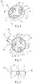
- FIG. 10 shows a perspective view of a spacer 10, the spacer 10 having an annular element 11 and three support elements 12. Furthermore, 12 bores 19 are provided in each of the three support elements. In particular, a bore 19 is provided in each support element 12.
- the hole 19 can be a through hole or a blind hole.
- the support elements 12 are attached to an inner surface 14 of the annular element 11. A radius can be provided as a transition between the respective support element 12 and the inner surface 14.
- the respective support elements 12 have an end face at an end 15 facing away from the inner face 14.
- Fig. 1 also shows a cylindrical outer surface 20 with a predetermined surface quality.
- the cylindrical outer surface 20 is designed to have an in Fig. 1 to keep outer conductor not shown at a distance.
- the end faces 16 provided on the end 15 facing away from the inner face 14 have a curved shape.
- a curved end face 16 is thus provided at the end 15 facing away from the inner surface 14 of the annular element 11.
- the support elements 12 are arranged at regular intervals along a circumferential direction 17 of the annular element 11.
- the support elements 12 are each equally spaced from one another along the circumferential direction 17.
- the angle between the radial directions 13 of the respective support elements 12 is preferably 120 ° in each case.
- the annular element 11 of the spacer 10 also has a center point which lies on an axis of rotation 18 of the annular element 11.
- Fig. 3 shows a sectional view through the spacer 10, in particular through the annular element 11.
- the annular element 11 can have a bevel on its edges, in particular on the edges delimiting the inner surface 14.
- the support element 12 can have an oval shape or a plan shape deviating from a circular shape in a plan on the inner surface 14.
- the end face 16 is in Fig. 3 shown in a top view.
- the axis of rotation 18 of the annular element 11 or of the spacer 10 is shown. The axis of rotation 18 runs through the center of the annular element 11.
- Fig. 4 shows a further example of a spacer 10, which has an annular element 11 and three support elements 12. There are in the support elements 12 in each case a bore 19, which can be designed, for example, as a through bore or as a blind bore, is provided.
- the outer surface 20 of the annular element 11 is again designed, one in Fig. 4 to keep outer conductor not shown at a distance.
- curved end faces are provided on an end 15 of the respective support element 12 facing away from the inner surface 14.
- the support elements 12 are arranged along the circumferential direction 17 at regular, but preferably at the same, intervals from one another.
- the angle between the radial directions 13 of the respective support elements 12 is 120 °, for example.
- the radial directions 13 of the respective support elements run through the center of the annular element 11, which lies on the axis of rotation 18 of the annular element or of the spacer 10.
- Fig. 6 shows the spacer 10, in which the annular element 11 is shown in section. It can be seen that the support element 12 has a plan area in the area of the inner surface 14 of the annular element 11 which deviates from a circular shape or is oval. It is also possible for the annular element 11 to have chamfers on the edges, in particular in the region of the inner surface 14.
- the embodiment shown of the spacer 10 has round support elements 12. Furthermore, material reinforcements are provided here in the area of the inclined bores 19 of the support elements 12.
- the material reinforcement has, for example, the shape of an attached spherical shape.
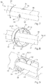
- Fig. 7 shows a rod-shaped inner conductor 30 with recesses 31 which are provided in a surface 37 of the rod-shaped inner conductor 30.
- the recesses 31 are provided in a row on the surface 37 of the rod-shaped inner conductor 30 along a circumferential direction 33 of the rod-shaped inner conductor. At least three recesses 31 can be provided on the surface 37 of the rod-shaped inner conductor 30.
- the recesses 31 are provided as blind bores, a base area 34 of the respective recesses 31 having a curved contour.
- the base area 34 of the recesses 31 has a single curved shape, the base area 34 being curved with respect to an axis of rotation which runs parallel to and preferably at a distance from an axis of rotation 35 of the rod-shaped inner conductor 30.
- the curved base surface 34 has a radius, the center of which does not lie on the axis of rotation 35 of the rod-shaped inner conductor 30.
- Fig. 8 shows a rod-shaped inner conductor 30 and a spacer 10 which is in engagement with the rod-shaped inner conductor 30.
- the spacer 10 has an annular element 11 with an inner surface 14.
- the support elements 12 protrude from the inner surface 14 in the radial direction of the annular element 11.
- Radial direction means that the support elements protrude in the direction of a center point of the annular element 11 from the inner surface 14 and thus the radial direction in the in Fig. 8
- the example shown extends through the axis of rotation 18 of the annular element 11, but also through the axis of rotation 35 of the rod-shaped inner conductor 30.
- the support elements 12 protrude into the recesses 31 which are provided in the surface 37 of the rod-shaped inner conductor 30.
- Fig. 9 shows an outer conductor 50 in a cut-away representation as well as the rod-shaped inner conductor 30 in which the spacer 10 engages.
- the Fig. 9 thus corresponds to in Fig. 8 illustrated case, where in Fig. 9 the outer conductor 50 of the coaxial measuring probe is also shown.
- the spacer 10 is designed in particular to keep or set a distance A between the rod-shaped inner conductor 30 and the outer conductor 50 essentially constant.
- An air gap can be provided between the outer surface 20 of the spacer 10 and the outer conductor 50, so that there is almost no play between the spacer 10 and the outer conductor 50. Forces can thus be effectively transmitted between the rod-shaped inner conductor 30 and the outer conductor 50 via the spacer 10.
- the distance A between the outer conductor 50 and the rod-shaped inner conductor 30 can be kept essentially constant, even if lateral forces act on the rod-shaped inner conductor 30 or the outer conductor 50, such as vibration loads.
- Fig. 10 shows a tool 60 for mounting the spacer 10 on the rod-shaped inner conductor 30.
- the rod-shaped inner conductor 30 is shown in FIG Fig. 10 not shown.
- the tool 60 has an annular clamping device 62 with at least three pin elements 63.
- the tool 60 also has a rough surface 61 for actuating the tool 60.
- the pin elements 63 each have a longitudinal axis 64, the longitudinal axes 64 of the individual pin elements 63 being arranged inclined to one another.
- the pin elements 63 are movably supported in the annular clamping device 62, see above that the longitudinal axes 64 of the respective pin elements 63 always intersect at one point. However, it is also possible that the longitudinal axes 64 of the individual pin elements 63 do not intersect at one point.
- the spacer 10 is also provided on the tool 60. In particular, the spacer 10 is plugged or pushed onto the tool 60 in order to mount it on the rod-shaped inner conductor.
- Fig. 12 it can be seen that the pin elements 63 of the tool 60 are pushed through the bores 19 of the respective support elements 12. Furthermore, in Fig. 12 It can be seen that the pin elements 63 are arranged along a circumferential direction 65 of the tool 60 on an end face 66 of the annular clamping device 62 at regular intervals. For example, the pin elements 63 are also arranged at equal distances from one another along the circumferential direction 65 of the annular clamping device 62. The spacer 10 is pretensioned by pushing the pin elements 63 of the tool 60 through the bores 19 of the respective support elements 12. The tool 60 is displaced along the axis of rotation 18 of the annular element 11.
- the spacer 10 is therefore pushed onto the tool 60. It is possible for the tool 60 to preload the spacer 10 by moving the pin elements 63 in the directions marked by arrows 67.
- the pin elements 63 can be designed to hold the spacer 10 for mounting on the in Fig. 12 bar-shaped inner conductor 30, not shown, by reducing an angle between the longitudinal axes 64 of at least two pin elements 63, but preferably all three pin elements 63.
- the spacer 10 is pretensioned by simply pushing the pin elements 63 through the bores 19 of the support elements 12.
- the deformation of the annular element 11 of the spacer 10 is shown in FIG Fig. 12 clearly visible.
- the spacer 10 or the annular element 11 is expanded at the points at which the pin elements 63 are located.
- Fig. 13 shows the positioning of the spacer 10 on the rod-shaped inner conductor 30, the spacer 10 being pretensioned with the aid of the pin elements 63 of the tool 60.
- the spacer 10 can be prestressed by the pin elements 63 in such a way that the curved end faces 16 of the support elements 12 can be guided along or on the surface 37 of the rod-shaped inner conductor 30. In other words, the spacer 10 is pushed over the surface 37 of the rod-shaped inner conductor 30 to the corresponding position on the rod-shaped inner conductor 30.
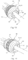
- Fig. 15 shows a side view of a rod-shaped inner conductor 30.
- the rod-shaped inner conductor 30 has a fastening unit 80, for example a screw connection, at a first end of the rod-shaped inner conductor 30, via which the rod-shaped inner conductor 30 is fastened to a measuring device.
- the outer conductor 50 can also be attached to this measuring device, so that the rod-shaped inner conductor 30 is only connected to the outer conductor 50 via the measuring device, since a small air gap can be provided between the spacer 10 and the outer conductor 50.
- the rod-shaped inner conductor 30 also has a first row 32 with at least three recesses 31 along one
- the spacer 10 is in Fig. 15 not shown.
- only one recess 31 of the first row 32 is shown completely.
- the rod-shaped inner conductor 30 also has a second row 36 with at least three recesses 31 along a circumferential direction 33 of the rod-shaped inner conductor 30 for receiving a support element 12 of a further not in each case Fig. 15 spacer 10 shown.
- only one recess 31 of the second row 36 of recesses 31 is shown completely.
- the second row 36 with at least three recesses 31 is arranged in the region of a second end of the rod-shaped inner conductor 30.
- the first row 32 with the at least three recesses 31 is arranged approximately centrally between the fastening unit 80 and the second row 36 with at least three recesses 31 on the rod-shaped inner conductor 30.
- Fig. 16 shows the rod-shaped inner conductor 30 and the outer conductor 50, the outer conductor 50 being held at a distance A from the rod-shaped inner conductor 30 by precisely two spacers 10.
- the spacers 10 are designed to hold the rod-shaped inner conductor 30 essentially coaxially to the outer conductor 50, or to keep it at a distance.
- the axis of rotation 18 of the spacer 10 lies on the axis of rotation 35 of the rod-shaped inner conductor 30 when the level measuring probe is in an assembled state and the rod-shaped inner conductor 30 and the outer conductor 50 are aligned coaxially to one another.
- Fig. 17 shows a side view of a level measuring probe 70 with an outer conductor 50.
- Several bores can be provided in the outer conductor 50, which are offset from one another.
- the rod-shaped inner conductor 30 and the spacers 10 are covered by the outer conductor 50.
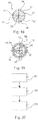
- Fig. 18 shows a sectional view of a rod-shaped inner conductor 30, the rod-shaped inner conductor 30 having recesses 31, in particular depressions, in the surface 37 of the rod-shaped inner conductor 30.
- the recesses 31 each have a base area 34, each base area 34 having a radius whose center point does not lie on the axis of rotation 35 of the rod-shaped inner conductor 30.
- the base surfaces 34 of the recesses 31 are designed to accommodate the curved end surfaces 16 of the support elements 12 of the spacer 10.
- the spacer 10 is in Fig. 18 not shown.
- Fig. 19 shows a sectional view through an outer conductor 50 and a rod-shaped inner conductor 30 of a coaxial fill level measuring probe 70 and a plan view of a spacer 10.
- the support elements 12 of the spacer 10 engage in the Fig. 19 Recesses 31, not shown, on the surface 37 of the rod-shaped inner conductor 30 in order to align the outer conductor 50 coaxially with the rod-shaped inner conductor 30 or to keep it at a distance.
- the axis of rotation 18 of the spacer 10 lies on the axis of rotation 35 of the rod-shaped inner conductor 30.
- Fig. 20 shows a flowchart for an assembly method for assembling a spacer 10 on a rod-shaped inner conductor 30.
- the spacer 10 is pretensioned so that the support elements 12 of the annular element 11 are positioned above a surface 37 of the rod-shaped inner conductor 30 along an axis of rotation 35 of the rod-shaped inner conductor 30 can be guided.
- the spacer 10 is positioned in relation to the rod-shaped inner conductor 30.
- the spacer 10 is guided over the rod-shaped inner conductor 30 or pushed onto the rod-shaped inner conductor 30 and positioned over the recesses 31 of the rod-shaped inner conductor 30 .
- the spacer 10 is relaxed so that the support elements 12 of the annular element 11 engage in corresponding recesses 31 of the rod-shaped inner conductor 30.
Landscapes
- Physics & Mathematics (AREA)
- General Physics & Mathematics (AREA)
- Electromagnetism (AREA)
- Fluid Mechanics (AREA)
- Thermal Sciences (AREA)
- Engineering & Computer Science (AREA)
- Mechanical Engineering (AREA)
- Measuring Leads Or Probes (AREA)
Claims (13)
- Écarteur (10) pour maintenir un écart (A) entre un conducteur interne en forme de tige (30) et un conducteur externe (50) d'une sonde de mesure de niveau de remplissage (70), comprenant :un élément annulaire (11) ;au moins trois éléments de support (12) faisant chacun saillie dans une direction radiale (13) à partir d'une surface intérieure (14) de l'élément annulaire (11) ;chacun des trois éléments de support (12) possédant une face d'extrémité (16) incurvée à une extrémité (15) éloignée de la surface intérieure (14) ; etl'extrémité (15) étant opposée à la surface intérieure (14) est conçue pour s'engager dans un évidement (31) du conducteur interne en forme de tige (30) ;caractérisé en ce queles au moins trois éléments de support (12) ont chacun un perçage (19) ; etles axes des perçages (19) traversant les éléments de support (12) sont chacun inclinés par rapport à un axe de rotation (18) de l'élément annulaire (11).
- Écarteur (10) selon la revendication 1,
dans lequel les au moins trois éléments de support (12) se rétrécissent dans la direction radiale (13). - Écarteur (10) selon l'une quelconque des revendications précédentes,
dans lequel les au moins trois éléments de support (12) sont disposés à intervalles réguliers le long d'une direction circonférentielle (17) de l'élément annulaire (11). - Écarteur (10) selon l'une quelconque des revendications précédentes,
dans lequel la face d'extrémité (16) incurvée de l'élément de support (12) respectif présente un rayon dont le centre ne se trouve pas sur un axe de rotation (18) de l'élément annulaire (11). - Écarteur (10) selon l'une quelconque des revendications précédentes,
dans lequel les axes respectifs des perçage (19) traversant les éléments de support (12) se croisent en un point commun qui se trouve sur l'axe de rotation (18) de l'élément annulaire (11). - Écarteur (10) selon l'une quelconque des revendications précédentes,
dans lequel l'écarteur (10) est en matière plastique. - Conducteur interne en forme de tige (30) d'une sonde de mesure (70), comprenant :une première rangée (32) avec au moins trois évidements (31) le long d'une direction circonférentielle (33) du conducteur interne (30) en forme de tige pour recevoir dans chaque cas un élément de support (12) d'un écarteur (10) ;caractérisé en ce queles évidements (31) comprennent chacun une surface de base (34) incurvée avec un rayon, dont le centre ne se trouve pas sur un axe de rotation (35) du conducteur interne (30) en forme de tigeles évidements (31) sont prévus comme des trous borgnes ; etle rayon de la surface de base incurvée correspond au rayon de la surface du conducteur interne en forme de tige (30).
- Conducteur interne en forme de tige (30) selon la revendication 7,
dans lequel la surface de base incurvée (34) des évidements (31) est simplement incurvée et un axe de rotation de la surface de base simplement incurvée (34) et l'axe de rotation (35) du conducteur interne en forme de tige (30) sont espacés l'un de l'autre. - Conducteur interne en forme de tige (30) selon l'une des revendications 7 ou 8, comprenant :une deuxième rangée (36) avec au moins trois évidements (31) le long d'une direction circonférentielle (33) du conducteur interne en forme de tige (30) pour recevoir dans chaque cas un élément de support (12) d'un écarteur (10) ;dans lequel la deuxième rangée (36) avec les au moins trois évidements (31) et la première rangée (32) avec les au moins trois évidements (31) sont espacées l'une de l'autre le long d'un axe de rotation (35) du conducteur interne en forme de tige (30).
- Sonde de mesure (70) pour déterminer un niveau de remplissage d'un milieu situé dans un contenant, comprenant :au moins un écarteur (10) selon l'une des revendications 1 à 6 ;un conducteur interne en forme de tige (30) ayant au moins trois évidements (31) le long d'une direction circonférentielle (33) du conducteur interne en forme de tige (30),un conducteur externe (50) ;dans lequel l'écarteur (10) est configuré pour maintenir le conducteur externe (50) et le conducteur interne en forme de tige (30) sensiblement coaxiale l'un par rapport à l'autre par engagement des éléments de support (12) dans les évidements (31) du conducteur interne en forme de tige (30).
- Sonde de mesure (70) selon la revendication 10, comprenant :dans lequel le conducteur intérieur en forme de tige (30) et le conducteur extérieur (50) sont alignés de manière sensiblement coaxiale l'un par rapport à l'autre au moyen de deux entretoises (10) espacées le long d'un axe de rotation (35) du conducteur intérieur en forme de tige (30).
- Sonde de mesure (70) selon l'une des revendications 10 ou 11,
dans lequel l'élément annulaire (11) de l'écarteur (10) comprend une surface extérieure cylindrique (20) ;
dans lequel un espace d'air est prévu entre la surface extérieure cylindrique (20) de l'élément annulaire (11) et une surface intérieure (51) du conducteur externe (5 - Méthode de montage pour monter un écarteur (10) selon l'une quelconque des revendications 1 à 7 sur un conducteur interne en forme de tige (30), comprenant les étapes suivantes :étirer l'écarteur (10) de sorte que les éléments de support (12) de l'élément annulaire (11) puissent être guidés sur une surface (37) du conducteur interne en forme de tige (30) le long d'un axe de rotation (35) du conducteur interne en forme de tige (30, S1) ;positionner l'écarteur (10) par rapport au conducteur interne en forme de tige (30, S2) ;relâcher l'écarteur (10) de sorte que les éléments de support (12) de l'élément annulaire (11) s'engagent dans des évidements correspondants (31) du conducteur interne en forme de tige (30, S3).
Priority Applications (3)
| Application Number | Priority Date | Filing Date | Title |
|---|---|---|---|
| EP16174228.3A EP3258224B1 (fr) | 2016-06-13 | 2016-06-13 | Ecarteur destine a conserver un ecart entre un conducteur interne en forme de tige et un conducteur externe d'une sonde de mesure de niveau de remplissage |
| US15/620,973 US10408657B2 (en) | 2016-06-13 | 2017-06-13 | Spacer to keep a distance between a bar-shaped inner conductor and an outer conductor of a filling level measuring probe |
| CN201710443414.5A CN107490333B (zh) | 2016-06-13 | 2017-06-13 | 间隔件、棒状内导体、测量探头、装配工具及装配方法 |
Applications Claiming Priority (1)
| Application Number | Priority Date | Filing Date | Title |
|---|---|---|---|
| EP16174228.3A EP3258224B1 (fr) | 2016-06-13 | 2016-06-13 | Ecarteur destine a conserver un ecart entre un conducteur interne en forme de tige et un conducteur externe d'une sonde de mesure de niveau de remplissage |
Publications (2)
| Publication Number | Publication Date |
|---|---|
| EP3258224A1 EP3258224A1 (fr) | 2017-12-20 |
| EP3258224B1 true EP3258224B1 (fr) | 2021-05-19 |
Family
ID=56120972
Family Applications (1)
| Application Number | Title | Priority Date | Filing Date |
|---|---|---|---|
| EP16174228.3A Active EP3258224B1 (fr) | 2016-06-13 | 2016-06-13 | Ecarteur destine a conserver un ecart entre un conducteur interne en forme de tige et un conducteur externe d'une sonde de mesure de niveau de remplissage |
Country Status (3)
| Country | Link |
|---|---|
| US (1) | US10408657B2 (fr) |
| EP (1) | EP3258224B1 (fr) |
| CN (1) | CN107490333B (fr) |
Families Citing this family (3)
| Publication number | Priority date | Publication date | Assignee | Title |
|---|---|---|---|---|
| US10340571B2 (en) * | 2017-02-22 | 2019-07-02 | Honeywell International Inc. | Rope conductor for guided wave radar coaxial waveguide |
| US10677634B2 (en) | 2017-07-05 | 2020-06-09 | Rosemount Tank Radar Ab | Radar level gauge system having longitudinally open two-conductor probe and method of assembly |
| US11339694B1 (en) * | 2021-01-15 | 2022-05-24 | GM Global Technology Operations LLC | Oil level indicator tube |
Citations (3)
| Publication number | Priority date | Publication date | Assignee | Title |
|---|---|---|---|---|
| US3260903A (en) * | 1963-07-30 | 1966-07-12 | Nippon Denshi Sokki Kabushiki | Electrical liquid level gauge |
| US20040177485A1 (en) * | 2001-08-29 | 2004-09-16 | Yaron Lihod | Boot-slider |
| US20130291957A1 (en) * | 2012-05-04 | 2013-11-07 | Caterpillar Inc. | Snap ring installation and removal tool |
Family Cites Families (29)
| Publication number | Priority date | Publication date | Assignee | Title |
|---|---|---|---|---|
| US2728546A (en) * | 1953-05-21 | 1955-12-27 | Liquidometer Corp | Vibration-resistant mounting for a capacitor type tank unit |
| US3214655A (en) * | 1962-05-29 | 1965-10-26 | Liquidometer Corp | Capacitive probe |
| GB999769A (en) * | 1963-11-11 | 1965-07-28 | Standard Telephones Cables Ltd | Electric cables |
| US3524116A (en) * | 1968-06-27 | 1970-08-11 | Honeywell Inc | Fluid level capacitor |
| IT1258132B (it) * | 1992-12-24 | 1996-02-20 | Dispositivo tastatore, particolarmente per macchine a copiare. | |
| US5651286A (en) * | 1996-07-23 | 1997-07-29 | Teleflex Incorporated | Microprocessor based apparatus and method for sensing fluid level |
| US6011391A (en) * | 1996-09-04 | 2000-01-04 | Elektro-Physik Hans Nix | Probe for measuring thin layers using a magnetic or eddy current process |
| US6016697A (en) * | 1997-09-09 | 2000-01-25 | American Magnetics, Inc. | Capacitive level sensor and control system |
| US6380746B1 (en) * | 1999-11-03 | 2002-04-30 | Eaton Corporation | Monitoring fluid condition with a spiral electrode configuration |
| US6380750B1 (en) * | 2000-10-25 | 2002-04-30 | William P. Schenck, Jr. | Capacitance probe and spacer therefor |
| US7354194B2 (en) * | 2003-01-06 | 2008-04-08 | Covidien Ag | Tympanic thermometer probe cover with film support mechanism |
| DE10308495A1 (de) | 2003-02-26 | 2004-09-16 | Endress + Hauser Gmbh + Co. Kg | Vorrichtung zur Bestimmung und/oder Überwachung des Füllstands eines Mediums in einem Behälter |
| US6988404B2 (en) * | 2003-12-11 | 2006-01-24 | Ohmart/Vega Corporation | Apparatus for use in measuring fluid levels |
| DE102004032965B4 (de) * | 2004-07-07 | 2015-03-05 | Endress + Hauser Gmbh + Co. Kg | Vorrichtung zum Ausrichten und Zentrieren eines stab- oder seilförmigen Oberflächenwellenleiters eines Feldgerätes |
| DE102006045940A1 (de) | 2006-09-28 | 2008-04-03 | Vega Grieshaber Kg | Abstandshalter für Koaxialinnenleiter |
| TWI426273B (zh) * | 2007-12-28 | 2014-02-11 | Mitsubishi Cable Ind Ltd | Probe and probe support construction |
| DE102008054942B4 (de) * | 2008-12-18 | 2021-02-11 | Endress+Hauser SE+Co. KG | Vorrichtung zur Bestimmung und/oder Überwachung einer Prozessgröße |
| DE102011009385A1 (de) * | 2011-01-25 | 2012-07-26 | Vega Grieshaber Kg | Füllstandmessgerät mit eiem Abstandshalter zur Zentrierung eines Innenstabes innen am Rohr |
| US8773302B2 (en) * | 2011-07-07 | 2014-07-08 | Rosemount Tank Radar Ab | Multi-channel radar level gauge |
| CN202351218U (zh) * | 2011-08-26 | 2012-07-25 | 吉林省电力有限公司电力科学研究院 | 大轴中心孔检测装置的支撑装置 |
| DE202012101989U1 (de) * | 2012-05-31 | 2013-09-02 | Sick Ag | Koaxialsonde für einen Füllstandssensor |
| EP2925961A1 (fr) * | 2012-12-03 | 2015-10-07 | Evolution Engineering Inc. | Sondes de fond de trou soutenues axialement |
| DE102012112318B4 (de) | 2012-12-14 | 2024-06-20 | Endress+Hauser SE+Co. KG | Vorrichtung zum Ausrichten und Zentrieren eines Oberflächenwellenleiters eines Feldgerätes |
| JP2014195497A (ja) * | 2013-03-29 | 2014-10-16 | セイコーエプソン株式会社 | 超音波プローブおよび音響カプラーアタッチメント並びに電子機器および超音波画像装置 |
| EP2977715B1 (fr) * | 2014-07-23 | 2017-12-06 | Tesa Sa | Support de sonde pour système de mesure |
| US9921096B2 (en) * | 2014-09-10 | 2018-03-20 | Honeywell International Inc. | Mechanical system for centering and holding a coax conductor in the center of an outer conductor |
| US20160334262A1 (en) * | 2015-05-11 | 2016-11-17 | Honeywell International Inc. | Tensioned coaxial probe for level measurement |
| US9711838B2 (en) * | 2015-10-29 | 2017-07-18 | Honeywell International Inc. | Indexed centering spacer for coaxial probes in guided wave radar level transmitters |
| CN205301247U (zh) * | 2016-01-05 | 2016-06-08 | 中国石油大学(北京) | 一种适用于针型探头声发射定位的实验夹具 |
-
2016
- 2016-06-13 EP EP16174228.3A patent/EP3258224B1/fr active Active
-
2017
- 2017-06-13 US US15/620,973 patent/US10408657B2/en active Active
- 2017-06-13 CN CN201710443414.5A patent/CN107490333B/zh active Active
Patent Citations (3)
| Publication number | Priority date | Publication date | Assignee | Title |
|---|---|---|---|---|
| US3260903A (en) * | 1963-07-30 | 1966-07-12 | Nippon Denshi Sokki Kabushiki | Electrical liquid level gauge |
| US20040177485A1 (en) * | 2001-08-29 | 2004-09-16 | Yaron Lihod | Boot-slider |
| US20130291957A1 (en) * | 2012-05-04 | 2013-11-07 | Caterpillar Inc. | Snap ring installation and removal tool |
Also Published As
| Publication number | Publication date |
|---|---|
| CN107490333B (zh) | 2021-12-03 |
| EP3258224A1 (fr) | 2017-12-20 |
| US10408657B2 (en) | 2019-09-10 |
| CN107490333A (zh) | 2017-12-19 |
| US20170356783A1 (en) | 2017-12-14 |
Similar Documents
| Publication | Publication Date | Title |
|---|---|---|
| EP2276658B1 (fr) | Palier de mesure, notamment pour une paire de roues d un véhicule ferroviaire | |
| DE2827036C2 (de) | Halterung für einen Meßfühler | |
| DE2749998B2 (de) | Federkraftmeßgerät | |
| EP3258224B1 (fr) | Ecarteur destine a conserver un ecart entre un conducteur interne en forme de tige et un conducteur externe d'une sonde de mesure de niveau de remplissage | |
| DE102006045940A1 (de) | Abstandshalter für Koaxialinnenleiter | |
| EP2598279B1 (fr) | Procédé de fabrication d'un arbre à cames | |
| EP2960444B1 (fr) | Procédé et dispositif de mesure de distance | |
| EP3105459B1 (fr) | Procédé de fixation de composants | |
| DE60004441T2 (de) | System zur Sitzreproduzierbarkeit in einem Tastkopf mit einer Doppelverschiebung der Kontaktpunkte | |
| DE102017111743B3 (de) | Vorspannungsmessung mit Kraftmessbolzen | |
| DE2849010A1 (de) | Messgeraet zur feststellung der massgenauigkeit von kegeligen bohrungen | |
| DE102017208841B3 (de) | NMR-Probenkopf mit lösbarer HF-Dichtung | |
| DE102016114285B4 (de) | Flanschträger zum gegenseitigen Tragen einer Stellarmatur und eines Stellantriebs und Messeinrichtung | |
| DE102011007494B4 (de) | Konzept zum Bereitstellen einer Anlageschulter in einem zylinderförmigen Lagergehäuse | |
| DE102018120670A1 (de) | Messtastelement und Verfahren zum Vermessen des Innengewindes oder eines Innenprofils eines Werkstücks mit einem solchen Messtastelement | |
| DE102015213235B4 (de) | Wälzkörper eines Wälzlagers | |
| EP2950059B1 (fr) | Élément de fermeture pour appareil de mesure du niveau de remplissage et appareil de mesure du niveau de remplissage | |
| DE2636107A1 (de) | Ultraschallsonde zur materialpruefung, insbesondere an schrauben von reaktordruckbehaeltern | |
| WO2018024519A1 (fr) | Dispositif de mesure de force à axe simple ou à axes multiples pourvu de zone de déformation réduite | |
| DE102006025341B4 (de) | Handler mit Beschleunigungsvorrichtung zum Testen von elektronischen Bauelementen | |
| DE102016008472A1 (de) | Elektrodensonde zur Befundung auf Feuchtigkeit | |
| EP3473992B1 (fr) | Dispositif de mesure pour mesurer des forces mecaniques et / ou des contraintes dans un composant | |
| DE102014016468A1 (de) | Vorrichtung zur Messung einer Körperlänge | |
| EP4320363B1 (fr) | Corps de roulement équipé d'un dispositif de mesure | |
| DE102018107320A1 (de) | Kraftmesseinrichtung |
Legal Events
| Date | Code | Title | Description |
|---|---|---|---|
| PUAI | Public reference made under article 153(3) epc to a published international application that has entered the european phase |
Free format text: ORIGINAL CODE: 0009012 |
|
| STAA | Information on the status of an ep patent application or granted ep patent |
Free format text: STATUS: REQUEST FOR EXAMINATION WAS MADE |
|
| 17P | Request for examination filed |
Effective date: 20161219 |
|
| AK | Designated contracting states |
Kind code of ref document: A1 Designated state(s): AL AT BE BG CH CY CZ DE DK EE ES FI FR GB GR HR HU IE IS IT LI LT LU LV MC MK MT NL NO PL PT RO RS SE SI SK SM TR |
|
| STAA | Information on the status of an ep patent application or granted ep patent |
Free format text: STATUS: EXAMINATION IS IN PROGRESS |
|
| 17Q | First examination report despatched |
Effective date: 20200313 |
|
| GRAP | Despatch of communication of intention to grant a patent |
Free format text: ORIGINAL CODE: EPIDOSNIGR1 |
|
| STAA | Information on the status of an ep patent application or granted ep patent |
Free format text: STATUS: GRANT OF PATENT IS INTENDED |
|
| INTG | Intention to grant announced |
Effective date: 20201204 |
|
| RIC1 | Information provided on ipc code assigned before grant |
Ipc: G01F 23/284 20060101AFI20201120BHEP Ipc: B25B 27/06 20060101ALI20201120BHEP Ipc: H01P 3/06 20060101ALI20201120BHEP |
|
| GRAS | Grant fee paid |
Free format text: ORIGINAL CODE: EPIDOSNIGR3 |
|
| GRAA | (expected) grant |
Free format text: ORIGINAL CODE: 0009210 |
|
| STAA | Information on the status of an ep patent application or granted ep patent |
Free format text: STATUS: THE PATENT HAS BEEN GRANTED |
|
| AK | Designated contracting states |
Kind code of ref document: B1 Designated state(s): AL AT BE BG CH CY CZ DE DK EE ES FI FR GB GR HR HU IE IS IT LI LT LU LV MC MK MT NL NO PL PT RO RS SE SI SK SM TR |
|
| REG | Reference to a national code |
Ref country code: GB Ref legal event code: FG4D Free format text: NOT ENGLISH |
|
| REG | Reference to a national code |
Ref country code: CH Ref legal event code: EP |
|
| REG | Reference to a national code |
Ref country code: DE Ref legal event code: R096 Ref document number: 502016013049 Country of ref document: DE |
|
| REG | Reference to a national code |
Ref country code: AT Ref legal event code: REF Ref document number: 1394439 Country of ref document: AT Kind code of ref document: T Effective date: 20210615 |
|
| REG | Reference to a national code |
Ref country code: IE Ref legal event code: FG4D Free format text: LANGUAGE OF EP DOCUMENT: GERMAN |
|
| REG | Reference to a national code |
Ref country code: LT Ref legal event code: MG9D |
|
| REG | Reference to a national code |
Ref country code: NL Ref legal event code: MP Effective date: 20210519 |
|
| PG25 | Lapsed in a contracting state [announced via postgrant information from national office to epo] |
Ref country code: LT Free format text: LAPSE BECAUSE OF FAILURE TO SUBMIT A TRANSLATION OF THE DESCRIPTION OR TO PAY THE FEE WITHIN THE PRESCRIBED TIME-LIMIT Effective date: 20210519 Ref country code: FI Free format text: LAPSE BECAUSE OF FAILURE TO SUBMIT A TRANSLATION OF THE DESCRIPTION OR TO PAY THE FEE WITHIN THE PRESCRIBED TIME-LIMIT Effective date: 20210519 Ref country code: HR Free format text: LAPSE BECAUSE OF FAILURE TO SUBMIT A TRANSLATION OF THE DESCRIPTION OR TO PAY THE FEE WITHIN THE PRESCRIBED TIME-LIMIT Effective date: 20210519 Ref country code: BG Free format text: LAPSE BECAUSE OF FAILURE TO SUBMIT A TRANSLATION OF THE DESCRIPTION OR TO PAY THE FEE WITHIN THE PRESCRIBED TIME-LIMIT Effective date: 20210819 |
|
| PG25 | Lapsed in a contracting state [announced via postgrant information from national office to epo] |
Ref country code: GR Free format text: LAPSE BECAUSE OF FAILURE TO SUBMIT A TRANSLATION OF THE DESCRIPTION OR TO PAY THE FEE WITHIN THE PRESCRIBED TIME-LIMIT Effective date: 20210820 Ref country code: IS Free format text: LAPSE BECAUSE OF FAILURE TO SUBMIT A TRANSLATION OF THE DESCRIPTION OR TO PAY THE FEE WITHIN THE PRESCRIBED TIME-LIMIT Effective date: 20210919 Ref country code: LV Free format text: LAPSE BECAUSE OF FAILURE TO SUBMIT A TRANSLATION OF THE DESCRIPTION OR TO PAY THE FEE WITHIN THE PRESCRIBED TIME-LIMIT Effective date: 20210519 Ref country code: SE Free format text: LAPSE BECAUSE OF FAILURE TO SUBMIT A TRANSLATION OF THE DESCRIPTION OR TO PAY THE FEE WITHIN THE PRESCRIBED TIME-LIMIT Effective date: 20210519 Ref country code: RS Free format text: LAPSE BECAUSE OF FAILURE TO SUBMIT A TRANSLATION OF THE DESCRIPTION OR TO PAY THE FEE WITHIN THE PRESCRIBED TIME-LIMIT Effective date: 20210519 Ref country code: PL Free format text: LAPSE BECAUSE OF FAILURE TO SUBMIT A TRANSLATION OF THE DESCRIPTION OR TO PAY THE FEE WITHIN THE PRESCRIBED TIME-LIMIT Effective date: 20210519 Ref country code: NO Free format text: LAPSE BECAUSE OF FAILURE TO SUBMIT A TRANSLATION OF THE DESCRIPTION OR TO PAY THE FEE WITHIN THE PRESCRIBED TIME-LIMIT Effective date: 20210819 Ref country code: PT Free format text: LAPSE BECAUSE OF FAILURE TO SUBMIT A TRANSLATION OF THE DESCRIPTION OR TO PAY THE FEE WITHIN THE PRESCRIBED TIME-LIMIT Effective date: 20210920 |
|
| PG25 | Lapsed in a contracting state [announced via postgrant information from national office to epo] |
Ref country code: NL Free format text: LAPSE BECAUSE OF FAILURE TO SUBMIT A TRANSLATION OF THE DESCRIPTION OR TO PAY THE FEE WITHIN THE PRESCRIBED TIME-LIMIT Effective date: 20210519 |
|
| PG25 | Lapsed in a contracting state [announced via postgrant information from national office to epo] |
Ref country code: SK Free format text: LAPSE BECAUSE OF FAILURE TO SUBMIT A TRANSLATION OF THE DESCRIPTION OR TO PAY THE FEE WITHIN THE PRESCRIBED TIME-LIMIT Effective date: 20210519 Ref country code: SM Free format text: LAPSE BECAUSE OF FAILURE TO SUBMIT A TRANSLATION OF THE DESCRIPTION OR TO PAY THE FEE WITHIN THE PRESCRIBED TIME-LIMIT Effective date: 20210519 Ref country code: EE Free format text: LAPSE BECAUSE OF FAILURE TO SUBMIT A TRANSLATION OF THE DESCRIPTION OR TO PAY THE FEE WITHIN THE PRESCRIBED TIME-LIMIT Effective date: 20210519 Ref country code: DK Free format text: LAPSE BECAUSE OF FAILURE TO SUBMIT A TRANSLATION OF THE DESCRIPTION OR TO PAY THE FEE WITHIN THE PRESCRIBED TIME-LIMIT Effective date: 20210519 Ref country code: CZ Free format text: LAPSE BECAUSE OF FAILURE TO SUBMIT A TRANSLATION OF THE DESCRIPTION OR TO PAY THE FEE WITHIN THE PRESCRIBED TIME-LIMIT Effective date: 20210519 Ref country code: RO Free format text: LAPSE BECAUSE OF FAILURE TO SUBMIT A TRANSLATION OF THE DESCRIPTION OR TO PAY THE FEE WITHIN THE PRESCRIBED TIME-LIMIT Effective date: 20210519 Ref country code: ES Free format text: LAPSE BECAUSE OF FAILURE TO SUBMIT A TRANSLATION OF THE DESCRIPTION OR TO PAY THE FEE WITHIN THE PRESCRIBED TIME-LIMIT Effective date: 20210519 |
|
| REG | Reference to a national code |
Ref country code: CH Ref legal event code: PL |
|
| REG | Reference to a national code |
Ref country code: DE Ref legal event code: R097 Ref document number: 502016013049 Country of ref document: DE |
|
| REG | Reference to a national code |
Ref country code: BE Ref legal event code: MM Effective date: 20210630 |
|
| PLBE | No opposition filed within time limit |
Free format text: ORIGINAL CODE: 0009261 |
|
| STAA | Information on the status of an ep patent application or granted ep patent |
Free format text: STATUS: NO OPPOSITION FILED WITHIN TIME LIMIT |
|
| PG25 | Lapsed in a contracting state [announced via postgrant information from national office to epo] |
Ref country code: MC Free format text: LAPSE BECAUSE OF FAILURE TO SUBMIT A TRANSLATION OF THE DESCRIPTION OR TO PAY THE FEE WITHIN THE PRESCRIBED TIME-LIMIT Effective date: 20210519 Ref country code: LU Free format text: LAPSE BECAUSE OF NON-PAYMENT OF DUE FEES Effective date: 20210613 |
|
| 26N | No opposition filed |
Effective date: 20220222 |
|
| PG25 | Lapsed in a contracting state [announced via postgrant information from national office to epo] |
Ref country code: LI Free format text: LAPSE BECAUSE OF NON-PAYMENT OF DUE FEES Effective date: 20210630 Ref country code: IE Free format text: LAPSE BECAUSE OF NON-PAYMENT OF DUE FEES Effective date: 20210613 Ref country code: CH Free format text: LAPSE BECAUSE OF NON-PAYMENT OF DUE FEES Effective date: 20210630 |
|
| PG25 | Lapsed in a contracting state [announced via postgrant information from national office to epo] |
Ref country code: IS Free format text: LAPSE BECAUSE OF FAILURE TO SUBMIT A TRANSLATION OF THE DESCRIPTION OR TO PAY THE FEE WITHIN THE PRESCRIBED TIME-LIMIT Effective date: 20210919 Ref country code: AL Free format text: LAPSE BECAUSE OF FAILURE TO SUBMIT A TRANSLATION OF THE DESCRIPTION OR TO PAY THE FEE WITHIN THE PRESCRIBED TIME-LIMIT Effective date: 20210519 |
|
| PG25 | Lapsed in a contracting state [announced via postgrant information from national office to epo] |
Ref country code: IT Free format text: LAPSE BECAUSE OF FAILURE TO SUBMIT A TRANSLATION OF THE DESCRIPTION OR TO PAY THE FEE WITHIN THE PRESCRIBED TIME-LIMIT Effective date: 20210519 Ref country code: BE Free format text: LAPSE BECAUSE OF NON-PAYMENT OF DUE FEES Effective date: 20210630 |
|
| REG | Reference to a national code |
Ref country code: AT Ref legal event code: MM01 Ref document number: 1394439 Country of ref document: AT Kind code of ref document: T Effective date: 20210613 |
|
| PG25 | Lapsed in a contracting state [announced via postgrant information from national office to epo] |
Ref country code: AT Free format text: LAPSE BECAUSE OF NON-PAYMENT OF DUE FEES Effective date: 20210613 |
|
| PG25 | Lapsed in a contracting state [announced via postgrant information from national office to epo] |
Ref country code: HU Free format text: LAPSE BECAUSE OF FAILURE TO SUBMIT A TRANSLATION OF THE DESCRIPTION OR TO PAY THE FEE WITHIN THE PRESCRIBED TIME-LIMIT; INVALID AB INITIO Effective date: 20160613 |
|
| P01 | Opt-out of the competence of the unified patent court (upc) registered |
Effective date: 20230508 |
|
| PG25 | Lapsed in a contracting state [announced via postgrant information from national office to epo] |
Ref country code: CY Free format text: LAPSE BECAUSE OF FAILURE TO SUBMIT A TRANSLATION OF THE DESCRIPTION OR TO PAY THE FEE WITHIN THE PRESCRIBED TIME-LIMIT Effective date: 20210519 |
|
| PG25 | Lapsed in a contracting state [announced via postgrant information from national office to epo] |
Ref country code: MK Free format text: LAPSE BECAUSE OF FAILURE TO SUBMIT A TRANSLATION OF THE DESCRIPTION OR TO PAY THE FEE WITHIN THE PRESCRIBED TIME-LIMIT Effective date: 20210519 |
|
| PG25 | Lapsed in a contracting state [announced via postgrant information from national office to epo] |
Ref country code: TR Free format text: LAPSE BECAUSE OF FAILURE TO SUBMIT A TRANSLATION OF THE DESCRIPTION OR TO PAY THE FEE WITHIN THE PRESCRIBED TIME-LIMIT Effective date: 20210519 |
|
| PG25 | Lapsed in a contracting state [announced via postgrant information from national office to epo] |
Ref country code: MT Free format text: LAPSE BECAUSE OF FAILURE TO SUBMIT A TRANSLATION OF THE DESCRIPTION OR TO PAY THE FEE WITHIN THE PRESCRIBED TIME-LIMIT Effective date: 20210519 |
|
| PGFP | Annual fee paid to national office [announced via postgrant information from national office to epo] |
Ref country code: DE Payment date: 20250618 Year of fee payment: 10 |
|
| PGFP | Annual fee paid to national office [announced via postgrant information from national office to epo] |
Ref country code: GB Payment date: 20250620 Year of fee payment: 10 |
|
| PGFP | Annual fee paid to national office [announced via postgrant information from national office to epo] |
Ref country code: FR Payment date: 20250618 Year of fee payment: 10 |