EP3258568A1 - Zurückziehbare ladevorrichtung - Google Patents
Zurückziehbare ladevorrichtung Download PDFInfo
- Publication number
- EP3258568A1 EP3258568A1 EP16748695.0A EP16748695A EP3258568A1 EP 3258568 A1 EP3258568 A1 EP 3258568A1 EP 16748695 A EP16748695 A EP 16748695A EP 3258568 A1 EP3258568 A1 EP 3258568A1
- Authority
- EP
- European Patent Office
- Prior art keywords
- pulley
- charging apparatus
- roller assembly
- retractable
- retractable charging
- Prior art date
- Legal status (The legal status is an assumption and is not a legal conclusion. Google has not performed a legal analysis and makes no representation as to the accuracy of the status listed.)
- Withdrawn
Links
Images


Classifications
-
- H—ELECTRICITY
- H02—GENERATION; CONVERSION OR DISTRIBUTION OF ELECTRIC POWER
- H02J—ELECTRIC POWER NETWORKS; CIRCUIT ARRANGEMENTS OR SYSTEMS FOR SUPPLYING OR DISTRIBUTING ELECTRIC POWER; SYSTEMS FOR STORING ELECTRIC ENERGY
- H02J7/00—Circuit arrangements for charging or discharging batteries or for supplying loads from batteries
- H02J7/70—Circuit arrangements for charging or discharging batteries or for supplying loads from batteries characterised by the mechanical construction
- H02J7/751—Circuit arrangements for charging or discharging batteries or for supplying loads from batteries characterised by the mechanical construction concerning the insertion or the connection of the batteries
-
- H—ELECTRICITY
- H02—GENERATION; CONVERSION OR DISTRIBUTION OF ELECTRIC POWER
- H02J—ELECTRIC POWER NETWORKS; CIRCUIT ARRANGEMENTS OR SYSTEMS FOR SUPPLYING OR DISTRIBUTING ELECTRIC POWER; SYSTEMS FOR STORING ELECTRIC ENERGY
- H02J7/00—Circuit arrangements for charging or discharging batteries or for supplying loads from batteries
- H02J7/32—Circuit arrangements for charging or discharging batteries or for supplying loads from batteries for charging batteries from a charging set comprising a non-electric prime mover rotating at constant speed
-
- H—ELECTRICITY
- H02—GENERATION; CONVERSION OR DISTRIBUTION OF ELECTRIC POWER
- H02J—ELECTRIC POWER NETWORKS; CIRCUIT ARRANGEMENTS OR SYSTEMS FOR SUPPLYING OR DISTRIBUTING ELECTRIC POWER; SYSTEMS FOR STORING ELECTRIC ENERGY
- H02J7/00—Circuit arrangements for charging or discharging batteries or for supplying loads from batteries
- H02J7/50—Circuit arrangements for charging or discharging batteries or for supplying loads from batteries acting upon multiple batteries simultaneously or sequentially
-
- H—ELECTRICITY
- H02—GENERATION; CONVERSION OR DISTRIBUTION OF ELECTRIC POWER
- H02J—ELECTRIC POWER NETWORKS; CIRCUIT ARRANGEMENTS OR SYSTEMS FOR SUPPLYING OR DISTRIBUTING ELECTRIC POWER; SYSTEMS FOR STORING ELECTRIC ENERGY
- H02J7/00—Circuit arrangements for charging or discharging batteries or for supplying loads from batteries
- H02J7/70—Circuit arrangements for charging or discharging batteries or for supplying loads from batteries characterised by the mechanical construction
- H02J7/731—Circuit arrangements for charging or discharging batteries or for supplying loads from batteries characterised by the mechanical construction specially adapted for holding portable devices containing batteries
Definitions
- the present invention relates to a charging apparatus, and particularly to a retractable (take-in) charging apparatus.
- the prior art has not yet provided an apparatus for charging the mobile devices in public occasions, because there are special requirements for arrangement of a charging apparatus in public occasions, e.g. the convenience and simplicity of operation, the dust-proof performance of the charging apparatus, the safety, maintenance and service life of the charging apparatus, and the convenience, safety and feel at ease of users in the charging.
- the apparatus will give a cumbersome and disorderly appearance, and electric wires will tend to be damaged and even lead to leakage of electricity.
- a special platform is needed to accommodate the electric wires and the charged mobile power packs, so that the apparatus will become more cumbersome and disorderly and give user's a poor experience, e.g. the inconvenience caused to the users having to wait at the site and the crowded and chaotic scenario caused by the simultaneous charging of many mobile power packs.
- the prior art has not yet provided a good solution to the demand of charging mobile power packs in public occasions.
- An object of the present invention is to provide a retractable charging apparatus with simple and convenient operation.
- the present invention provides a retractable charging apparatus, characterized by comprising a retraction roller mechanism, a charging mechanism and a main control PCB, wherein the retraction roller mechanism includes a first driving device, a transmission assembly in driving connection to the first driving device, and at least one roller assembly connected with the transmission assembly; each of the at least one roller assembly includes two opposite rollers; the first driving device is electrically connected with the main control PCB; and the charging mechanism includes a charging PCB connected with the main control PCB.
- the main control PCB instructs the first driving device to drive the retraction roller mechanism.
- the power pack can be taken into the apparatus by the rolling of the rollers, and then conveyed to the charging mechanism for charging, and after the charging, the power pack is sent out by the retraction roller mechanism.
- the users can perform a simple, convenient and flexible operation, can stably and accurately convey the power pack to be charged to the charging contacts so as to ensure the accurate contact in the charging, without needing any laborious manual adjustment and alignment for charging; and the apparatus is fast and easy to operate, times-saving and labor-saving, has a good charging performance, can improve the charging efficiency while ensuring good charging contact, is environment-friendly, and can save power consumption.
- the retractable charging apparatus according to the present invention can be used for charging not only mobile power packs but also common power packs of mobile products.
- the at least one roller assembly may only include one roller assembly, or a first roller assembly and a second roller assembly, or a first roller assembly, a second roller and a third roller assembly, or more than three roller assemblies. These all fall within the protection scope of the present invention.
- the transmission assembly comprises a first pulley group including a first pulley connected with the first driving device, a second pulley connected with the first roller assembly, and a first belt connecting the first pulley with the second pulley.
- the transmission assembly may also use e.g. gear transmission, etc.
- the first belt is a toothed belt.
- the transmission assembly comprises a corresponding number of pulley groups, each pulley group including two pulleys and a belt, the two pulleys and the belt of a first pulley group being connected with the first driving device and a first roller assembly, and two adjacent roller assemblies are connected through two pulleys and a belt of the other pulley group(s).
- driving of the first driving device is transmitted to each roller assembly, and the roller assemblies cooperate to retract and convey the power pack.
- the belt is a toothed belt.
- the pulleys connected to each roller assembly can be arranged on the same side or on two sides of each roller assembly.
- the pulleys connected to each roller assembly are arranged on two sides of each roller assembly, so as to achieve space saving.
- the retraction roller mechanism comprises a first roller assembly and a second roller assembly
- the first roller assembly and the second roller assembly cooperate to convey the power pack.
- the transmission assembly can also be divided into two stages for connecting the first driving device with the first roller assembly and connecting the first roller assembly with the second roller assembly; alternatively, the two-stage transmission can connect the first driving device with the first roller assembly and connect the first driving device with the second roller assembly respectively.
- the transmission assembly may be embodied in various means, e.g. pulley group transmission, gear transmission, etc.
- the transmission assembly comprises: a first pulley group including a first pulley connected with the first driving device, a second pulley connected with the first roller assembly and a first belt connecting the first pulley with the second pulley; and a second pulley group including a third pulley connected with the first roller assembly, a fourth pulley connected with the second roller assembly, and a second belt connecting the third pulley with the fourth pulley.
- the first belt and the second belt are toothed belts.
- the second pulley and the third pulley can be arranged on the same side or on two sides of the first roller assembly.
- the second pulley and the third pulley are arranged on two sides of the first roller assembly, so as to achieve space saving.
- the transmission assembly comprises: a first pulley group including a first pulley connected with the first driving device, a second pulley connected with the first roller assembly, and a first belt connecting the first pulley with the second pulley; a second pulley group including a third pulley connected with the first roller assembly, a fourth pulley connected with the second roller assembly, and a second belt connecting the third pulley with the fourth pulley; and a third pulley group including a fifth pulley connected with the second roller assembly, a sixth pulley connected with the third roller assembly, and a third belt connecting the fifth pulley with the sixth pulley.
- the first belt, the second belt and the third belt are toothed belts.
- the second pulley and the third pulley can be arranged on the same side or on two sides of the first roller assembly, and the fourth pulley and the fifth pulley can be arranged on the same side or on two sides of the second roller assembly.
- the second pulley and the third pulley are arranged on two sides of the first roller assembly, and the fourth pulley and the fifth pulley are arranged on two sides of the second roller assembly, so as to save space.
- the first driving device is a motor.
- the retraction roller mechanism further comprises a inlet/outlet door mechanism.
- the inlet/outlet door mechanism comprises an eccentric shaft, a second driving device, guide rails, and a door vertically slidable along the guide rails, the second driving device being connected with the main control PCB, the eccentric shaft being connected with the second driving device, and the door including a cross bar disposed above and abutting against the eccentric shaft.
- the main control PCB instructs the second driving device to drive the eccentric shaft to rotate, the rotation of the eccentric shaft pushes the cross bar abutting against the eccentric shaft, which results in vertical sliding of the door along the guide rails and accordingly results in opening and closing of the door.
- the inlet/outlet door mechanism may also be embodied in other means, e.g. a manually opened door mechanism, an inductively opened door mechanism, etc.
- the door is provided with positioning posts for limiting movement of the door in the guide rails, thereby resulting in a stable movement of the door.
- the second driving device is a motor.
- the inlet/outlet door mechanism is further provided with guiding means for guiding entrance of the power pack.
- the guiding means conforms to the profile of the power pack to be charged so as to facilitate insertion of the power pack.
- the retractable charging apparatus further comprises a thru-beam sensor, which is arranged at the inlet of the retractable charging apparatus and is connected with the main control PCB.
- the thru-beam sensor is provided with a receiving end and a transmitting end arranged in a vertical direction in communication with each other through infrared rays.
- the thru-beam sensor can detect the in and out of the power pack.
- the power pack When the user introduces the power pack to be charged, the power pack obstructs the infrared rays between the two ends of the thru-beam sensor, and the thru-beam sensor produces a pulse signal such that the main control PCB is informed of entrance of the power pack and activates the first driving device so as to drive the transmission assembly, and the power pack is slowly retracted into the mechanism under the frictional force of the rollers.
- the thru-beam sensor can also detect whether the power pack has been ejected; and the thru-beam sensor can also be used to detect whether the ejected power pack has been taken away, and if not taken away overtime, the power pack will be retracted.
- the retractable charging apparatus comprises two thru-beam sensors arranged in front of and behind the first roller assembly respectively and connected with the main control PCB.
- this preferred embodiment can also be used to detect the speed and position of the inserted power pack, as well as the condition of ejection of the power pack so as to prevent the forced pull-out of the power pack, and if the forced pull-out is detected, driving is started to retract the power pack.
- the rollers are each coated with a rubber layer on the surface, and a space is formed between the surfaces of the each pair of rollers for accommodating and pushing the power pack.
- the rubber material which is flexible and wearing resistant, is in direct contact with the power pack, and the power pack is retracted under the rolling friction, so that the power pack can be protected from wearing.
- the distance between the rubber layers of the vertically-arranged rollers is slightly smaller than the thickness of the power pack such that the retraction movement of the power pack can be more stable and precise.
- the retractable charging apparatus further comprises slide rails, which are arranged between the opposite rollers.
- the slide rails can be used to guide the power pack in the retraction and ejection, and has a sectional shape conforming to two sides of the power pack to be charged so as to achieve a guiding effect.
- the slide rails can also be in a special shape if necessary for charging a special power pack and preventing entrance of another power pack in a different shape.
- the charging mechanism further comprises a PCB fixing seat, on which the charging PCB is arranged.
- the charging PCB is provided with at least two pins matching with the pole contacts of the power pack and electrically connected with the charging PCB. After the pole contacts of the power pack to be charged are brought into contact with the pins, a circuit is formed, and a data transmission is formed between the power pack and the main control PCB.
- the main control PCB reads various internal information of the power pack, e.g. charging capacity, temperature, ID information, current, etc., and can judge whether the insertion direction of the power pack is reversed, whether the power pack is a specific one which is permitted to be charged, or the like; and/or the main control PCB can input current into the power pack to achieve a charging function.
- the charging PCB is provided with four pins matching with the pole contacts of the power pack, wherein two pins are used for charging, and the other two pins are used for data transmission. If the power pack is inserted in an incorrect direction, the two pins for data transmission detect the incorrect insertion of the power pack, and the main control PCB will drive the first driving device to rotate in an opposite direction so as to convey the power pack out.
- the tip of the pin is of a retractable pogo pin design.
- the PCB fixing seat is provided with a pin guide, through which the pin is inserted so as to improve the position accuracy.
- the PCB fixing seat is provided with a position limiting part for limiting the insertion position of the power pack.
- the stress on the pin may be reduced and the service life of the pin may be increased.
- the retractable charging apparatus further comprises a trigger switch disposed on the PCB fixing seat and connected with the main control PCB.
- the trigger switch is a "snap dome" typed mechanical trigger switch, and can be used to judge whether the power pack has been retracted in position.
- the snap dome trigger switch When the power pack to be charged is inserted and retracted in position, the snap dome trigger switch will be compressed, and a switch signal will be produced and transmitted to the main control PCB, wherein the trigger switch has an in-position warning effect, so as to cause the first driving device to stop working.
- the retractable charging apparatus further comprises a left-side frame and a right-side frame, between which the first roller assembly and the second roller assembly are arranged.
- the left-side frame and the right-side frame have the effect of stabilizing and facilitating arrangement of various elements.
- the retractable charging apparatus further comprises a fixing shaft arranged between the left-side frame and the right-side frame, and locked by a nut.
- the fixing shaft can produce the effect of stabilizing the left-side frame and the right-side frame.
- the present invention has the following advantages: in the retractable charging apparatus according to the present invention, the main control PCB instructs the first driving device to drive the retraction roller mechanism.
- the power pack can be retracted into the apparatus under rolling of the rollers and then conveyed to the charging mechanism for charging, and after the charging, the power pack is conveyed out by the retraction roller mechanism.
- the operation is simple and convenient for users.
- rollers coated with the rubber layers allow a stable and safe movement of retraction or ejection of the power pack, cause no damage to the power pack, improve users' experience, and have a high operating safety. Since the power pack when being charged is housed in the retractable charging apparatus, there are no messy power lines, and the dust-proof performance, the safety and the user's experience are improved.
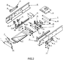
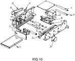
- the present invention provides a retractable (take-in) charging apparatus, comprising a retraction (take-in) roller mechanism, a charging mechanism, a main control PCB 11, and an inlet/outlet door mechanism.
- the retraction roller mechanism includes a first driving device (a first motor 13 in the present embodiment), a transmission assembly in driving connection to the first motor 13, and a first roller assembly 24 and a second roller assembly 25 connected to the transmission assembly. Each of the first roller assembly and the second roller assembly includes a pair of rollers.
- the first motor 13 is electrically connected with the main control PCB 11.
- the charging mechanism includes a charging PCB 18 connected with the main control PCB 11, and the charging PCB 18 is arranged on a PCB fixing seat 17.
- the inlet/outlet door mechanism is connected with the retraction roller mechanism.
- the transmission assembly comprises: a first pulley group including a first pulley 14 connected with a drive shaft of the first motor 13, a second pulley 16 connected with one side of the first roller assembly 24, and a first toothed belt 15 connecting the first pulley 14 with the second pulley 16; and a second pulley group including a third pulley 7 connected with the other side of the first roller assembly 24, a fourth pulley 5 connected with one side of the second roller assembly 25, and a second toothed belt 6 connecting the third pulley 7 with the fourth pulley 5.
- the inlet/outlet door mechanism comprises an eccentric shaft 2, a second driving device (a second motor 4 in the present embodiment), a left guide rail 3, a right guide rail 22, and a door 1 vertically slidable along the left guide rail 3 and the right guide rail 22, wherein the second motor 4 is eclectically with the main control PCB 11, and the eccentric shaft 2 is connected with the second motor 4.
- the door 1 comprises a cross bar 102 disposed above and abutting against the eccentric shaft 2, and positioning posts 101 disposed at both sides for engagement with the left guide rail 3 and the right guide rail 22, wherein the left guide rail 3 and the right guide rail 22 are each provided with a guide rail groove 221 and a guide structure 224; the positioning posts 101 on the door 1, after being placed in the guide rail groove 221, may have a position limiting effect on the door 1; and the guide structure 224 is used for facilitating arrangement of the power pack 27.
- a slide rail 222 is provided from between the upper and lower rollers of the first roller assembly 24 to between the upper and lower rollers of the second roller assembly 25, for guiding the power pack 27 in the retration and ejection operations.
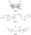
- the sectional shape of the slide rail 222 conforms with two sides of the power pack 27, as shown in Fig.3 .
- the left guide rail 3 and the right guide rail 22 each forms an integral unit with the slide rail 222, which is fixed to a left-side frame 8 and a right-side frame 12 of the retractable charging apparatus according to the present invention through positioning posts 301 disposed on the outer side of the slide rail 222.
- the front surface of the retractable charging apparatus forms a shape similar to the power pack 27 for the guiding thereof and additionally preventing entrance of another power pack in a different shape.
- the pair of vertically arranged rollers of the first roller assembly 24 and the pair of vertically arranged rollers of the second roller assembly 25 are each coated with a rubber layer 26 on the surface, and a gap for accommodating and pushing the power pack is formed between the surfaces of the pairs of rollers.
- the ends of the rollers are secured to the left-side frame 8 and the right-side frame 12 by bushings 23.
- the rubber material which is flexible and wearing resistant, is in direct contact with the power pack, and the power pack is taken in by rolling friction, so that the power pack can be protected from wearing.
- the distance between the rubber layers of the vertically-arranged rollers is slightly smaller than the thickness of the power pack to be charged such that movement of the taken-in power pack can be more stable and accurate.
- two thru-beam sensors 20, 21 are disposed both in front of and behind the second roller assembly 25 respectively, and are connected with the main control PCB 11.
- the slide rail 222 is provided with two sensor mounting seats 223 on which the thru-beam sensors 20, 21 are mounted, and the two thru-beam sensors can detect the in and out of the power pack.
- the two thru-beam sensors 20, 21 each are provided with an upper receiving end 211 and a lower transmitting end 212 in communication with each other through infrared rays.
- the power pack 27 When the user introduces a power pack to be charged, the power pack 27 obstructs the infrared rays between the thru-beam sensors, and the thru-beam sensors transmit a pulse signal such that the main control PCB 11 is informed of entrance of the power pack and activates the first motor 13 to drive the transmission assembly, and the power pack slowly enters into the mechanism under the frictional force of the rollers.
- the thru-beam sensors can also detect whether the power pack has been ejected and whether the ejected power pack has been taken away; if it is not taken away overtime, the transmission assembly will be driven to retract the power pack.
- the thru-beam sensors can also detect the speed and position of the power pack during the introduction as well as the condition of ejection of the power pack so as to prevent the forced pull-out of the power pack by a person, and if a forced pull-out is detected, driving is started to retract the power pack.
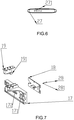
- the end surface of the power pack 27 to be charged is provided with pole contacts 271.
- the pole contact is made of copper and has a round contact surface
- the charging PCB 18 is provided with four pins 28, in which two pins used for charging match with the pole contacts 271 of the power pack, and the other two pins are used for data transmission.
- the pins 28 are electrically connected with the charging PCB 18.
- the main control PCB 11 can read various internal information of the power pack 27, e.g. charging capacity, temperature, ID information, current, etc., and can input current into the power pack 27 via the contact therebetween to achieve the charging function. Further, depending on whether the information of the power pack can be read through said contacts, it can be determined whether the power pack is inserted reversely, whether the power pack is a specific one permitted to be charged, and this is an important aspect for a "smart" apparatus. If the power pack is inserted in an incorrect direction and the two pins for data transmission detect the incorrect insertion of the power pack, the main control PCB will drive the first motor to rotate in an opposite direction so as to send the power pack out.
- various internal information of the power pack e.g. charging capacity, temperature, ID information, current, etc.
- the tip 281 of the pin 28 is retractable, and is of a pogo pin design.
- the PCB fixing seat 17 is provided with a pin guide 172 for improving the position accuracy when the pins 28 are inserted.
- the PCB fixing seat 17 is provided with a position limiting part 171 for limiting the position of the power pack when the power pack 27 is inserted in position, in order to reduce the stress on the pins 28 and improve the service life thereof.
- the retractable charging apparatus further comprises a trigger switch 19 disposed on the PCB fixing seat 17 and connected with the main control PCB 11.
- the trigger switch is a "snap dome" mechanical trigger switch and has an elastic sheet 191.
- a switch signal will be obtained and is transmitted to the main control PCB 11, wherein the trigger switch performs a function of in-position warning.
- the main control PCB 11 receives the in-position signal outputted by the trigger switch 19, and causes the first motor 13 to stop working.
- a fixing shaft 9 which is locked through a nut 10.
- the fixing shaft can stabilize the left-side frame and the right-side frame.
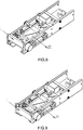
- the main control PCB instructs the second motor 14 to drive the eccentric shaft 2 of the inlet/outlet door mechanism so as to cause the door 1 to be opened upwards (see Fig.8 ).
- the power pack 27 obstructs the infrared rays, and the sensor 21 produces a pulse signal to inform the main control PCB 11 of the insertion of the power pack and then the first motor 13 is activated.
- the first motor 13 drives the retraction roller mechanism to operate by the two-stage transmission.
- the second roller assembly 25 and the first roller assembly 24 of the retraction roller mechanism operate, and the power pack 27 is taken in under the frictional force of the rollers, and is slowly introduced into the mechanism under the guiding of the left guide rail 3 and the right guide rail 22.
- the elastic sheet 191 is actuated, and the trigger switch 19 outputs an in-position signal to the main control PCB 11, which causes the first motor 13 to stop working.
- the main control PCB 11 will read information of the power pack; and if no information of the power pack can be read, the main control PCB 11 will instruct the retraction roller mechanism to operate in an opposite direction so as to eject the power pack.
- the power pack can be taken into the apparatus by the rolling of the rollers; the power pack is conveyed through the second roller assembly and the first roller assembly to the charging mechanism for charging; and after the charging, the power pack is sent out by the first roller assembly and the second roller assembly of the retraction (take-in) roller mechanism.
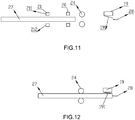
- Embodiment 2 of the retractable charging apparatus differs from Embodiment 1 in that the retraction roller mechanism in the present Embodiment 2 only uses a first roller assembly 24, and the transmission assembly comprises a first pulley group including a first pulley 14 connected with a drive shaft of the first motor 13, a second pulley 16 connected with one side of the first roller assembly 24, and a toothed belt 15 connecting the first pulley with the second pulley.
- Two thru-beam sensors 20, 21 can be spaced apart and arranged in front of the first roller assembly 24, or can be arranged in front of and behind the first roller assembly 24 respectively.
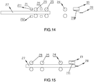
- Embodiment 3 of the retractable charging apparatus differs from Embodiment 1 and Embodiment 2 in that the retraction roller mechanism in the present Embodiment 3 comprises a first roller assembly 24, a second roller assembly 25 and a third roller assembly 29, and the transmission assembly comprises: a first pulley group including a first pulley 14 connected with a drive shaft of a first motor 13, a second pulley 16 connected with one side of the first roller assembly 24, and a first toothed belt 15 connecting the first pulley with the second pulley; a second pulley group including a third pulley 7 connected with the other side of the first roller assembly 24, a fourth pulley 5 connected with one side of the second roller assembly 25, and a second belt 6 connecting the third pulley 7 with the fourth pulley 5; and a third pulley group including a fifth pulley 141 connected with the other side of the second roller assembly 25, a sixth pulley 161 connected with one side of the
Landscapes
- Engineering & Computer Science (AREA)
- Power Engineering (AREA)
- Charge And Discharge Circuits For Batteries Or The Like (AREA)
Applications Claiming Priority (3)
| Application Number | Priority Date | Filing Date | Title |
|---|---|---|---|
| PCT/CN2015/072894 WO2016127359A1 (zh) | 2015-02-12 | 2015-02-12 | 吸纳式充电装置 |
| PCT/CN2015/072904 WO2016127363A1 (zh) | 2015-02-12 | 2015-02-12 | 移动电源自动租赁设备 |
| PCT/CN2016/073358 WO2016127894A1 (zh) | 2015-02-12 | 2016-02-03 | 吸纳式充电装置 |
Publications (2)
| Publication Number | Publication Date |
|---|---|
| EP3258568A1 true EP3258568A1 (de) | 2017-12-20 |
| EP3258568A4 EP3258568A4 (de) | 2018-08-22 |
Family
ID=56614154
Family Applications (1)
| Application Number | Title | Priority Date | Filing Date |
|---|---|---|---|
| EP16748695.0A Withdrawn EP3258568A4 (de) | 2015-02-12 | 2016-02-03 | Zurückziehbare ladevorrichtung |
Country Status (6)
| Country | Link |
|---|---|
| US (1) | US10615619B2 (de) |
| EP (1) | EP3258568A4 (de) |
| JP (1) | JP6437673B2 (de) |
| CN (1) | CN205509546U (de) |
| SG (1) | SG11201705360WA (de) |
| WO (1) | WO2016127894A1 (de) |
Families Citing this family (5)
| Publication number | Priority date | Publication date | Assignee | Title |
|---|---|---|---|---|
| EP3258568A4 (de) | 2015-02-12 | 2018-08-22 | Shenzhen Laidian Technology Co., Ltd. | Zurückziehbare ladevorrichtung |
| US11385681B1 (en) | 2020-08-05 | 2022-07-12 | Bretford Manufacturing, Inc. | Docking computer storage system |
| CN113241833B (zh) * | 2021-05-11 | 2023-04-14 | 诠航科技有限公司 | 一种隧道机 |
| CN114259252B (zh) * | 2021-11-18 | 2022-09-06 | 浙江大学滨江研究院 | 一种听诊器套装 |
| CN117614079B (zh) * | 2023-12-14 | 2024-12-17 | 江西京九电源(九江)有限公司 | 一种铅酸蓄电池的充电装置 |
Family Cites Families (33)
| Publication number | Priority date | Publication date | Assignee | Title |
|---|---|---|---|---|
| JP3515859B2 (ja) * | 1995-09-29 | 2004-04-05 | 株式会社リコー | 電池充電処理装置及び電池充電処理システム |
| US6496685B2 (en) * | 1998-06-15 | 2002-12-17 | Qualcomm, Incorporated | Portable phone with imbedded battery |
| JP2000090348A (ja) * | 1998-09-09 | 2000-03-31 | Honda Motor Co Ltd | バッテリ充電装置及びバッテリ返却装置 |
| CN1319242C (zh) * | 1998-12-04 | 2007-05-30 | 精工爱普生株式会社 | 电子机器与电子机器的供电方法 |
| JP4479977B2 (ja) * | 1999-05-25 | 2010-06-09 | 本田技研工業株式会社 | バッテリ交換装置 |
| IT1320305B1 (it) | 1999-05-25 | 2003-11-26 | Honda Motor Co Ltd | Apparecchiatura per il cambio di batterie. |
| JP2001101526A (ja) | 1999-09-30 | 2001-04-13 | Matsushita Electric Ind Co Ltd | 充電装置 |
| JP2001266954A (ja) * | 2000-03-15 | 2001-09-28 | Sony Corp | 電池充電販売装置及び電池充電販売方法 |
| JP2004013559A (ja) | 2002-06-07 | 2004-01-15 | Toshiba Tec Corp | カード処理装置 |
| JP4208513B2 (ja) * | 2002-07-25 | 2009-01-14 | キヤノン株式会社 | 画像形成装置 |
| CN1991896A (zh) | 2005-12-31 | 2007-07-04 | 财团法人工业技术研究院 | 一种储能装置及其租赁管理系统与方法 |
| ES2461867T3 (es) * | 2007-04-02 | 2014-05-21 | Mitoshi Ishii | Batería de almacenamiento, dispositivo de alojamiento de batería de almacenamiento, dispositivo de carga de batería de almacenamiento y dispositivo para el abono de los gastos de uso para una batería de almacenamiento |
| CN101217237A (zh) | 2008-01-18 | 2008-07-09 | 北京电巴科技有限公司 | 一种车用动力电池存储及充电平台 |
| JP2009201276A (ja) * | 2008-02-22 | 2009-09-03 | Okamura Corp | 可搬型電源装置の収納庫 |
| CN102082309B (zh) * | 2009-11-27 | 2014-09-17 | 尹学军 | 电动车辆快速补充电能的方法及其供电装置 |
| JP5184566B2 (ja) * | 2010-03-12 | 2013-04-17 | 株式会社コナミデジタルエンタテインメント | 充電装置およびゲーム装置 |
| JP5465155B2 (ja) * | 2010-11-16 | 2014-04-09 | 日立オムロンターミナルソリューションズ株式会社 | カード処理ユニット、および自動取引処理装置 |
| CN102005090A (zh) | 2010-12-06 | 2011-04-06 | 深圳市瑞摩特科技发展有限公司 | 具有商品销售与售后服务功能的自动售货机 |
| JP2012191701A (ja) | 2011-03-09 | 2012-10-04 | Sumitomo Forestry Co Ltd | 蓄電池搭載機器の蓄電池充放電構造 |
| US9123035B2 (en) * | 2011-04-22 | 2015-09-01 | Angel A. Penilla | Electric vehicle (EV) range extending charge systems, distributed networks of charge kiosks, and charge locating mobile apps |
| TWI420775B (zh) * | 2011-05-26 | 2013-12-21 | 鴻海精密工業股份有限公司 | 具有安全功能的充電座 |
| US20130132307A1 (en) | 2011-11-17 | 2013-05-23 | Rwdg Enterprises, Inc. | Managing the use of secure compartments in charging stations for portable electronic devices |
| CN202772633U (zh) | 2012-09-13 | 2013-03-06 | 上海电巴新能源科技有限公司 | 电动车车载动力电池充电平台 |
| CN203151138U (zh) | 2013-01-28 | 2013-08-21 | 上海普天能源科技有限公司 | 一种电池充电机柜 |
| CN203644131U (zh) | 2013-12-16 | 2014-06-11 | 深圳市拓特电子有限公司 | 充电器租售机 |
| CN103646470B (zh) | 2013-12-16 | 2016-06-29 | 深圳市拓特电子有限公司 | 充电器租售机 |
| US9407048B2 (en) * | 2014-08-07 | 2016-08-02 | Cordcase Llc | Protective case for portable electronic device with integrated dispensable and retractable charge and sync cable |
| DE102014016434B3 (de) | 2014-11-03 | 2016-03-17 | Audi Ag | Verfahren zum Betreiben einer Aufnahmevorrichtung, Aufnahmevorrichtung und Kraftwagen mit einer Aufnahmevorrichtung |
| CN104603849B (zh) * | 2015-02-12 | 2017-03-15 | 深圳来电科技有限公司 | 移动电源自动租赁设备 |
| CN204557649U (zh) * | 2015-02-12 | 2015-08-12 | 深圳来电科技有限公司 | 移动电源自动租赁设备 |
| CN204424974U (zh) | 2015-02-12 | 2015-06-24 | 深圳来电科技有限公司 | 吸纳式充电装置 |
| EP3258568A4 (de) | 2015-02-12 | 2018-08-22 | Shenzhen Laidian Technology Co., Ltd. | Zurückziehbare ladevorrichtung |
| CN107487195A (zh) * | 2016-06-13 | 2017-12-19 | 飞宏科技股份有限公司 | 移动式充电装置 |
-
2016
- 2016-02-03 EP EP16748695.0A patent/EP3258568A4/de not_active Withdrawn
- 2016-02-03 US US15/546,649 patent/US10615619B2/en active Active
- 2016-02-03 CN CN201620112192.XU patent/CN205509546U/zh not_active Expired - Lifetime
- 2016-02-03 SG SG11201705360WA patent/SG11201705360WA/en unknown
- 2016-02-03 WO PCT/CN2016/073358 patent/WO2016127894A1/zh not_active Ceased
- 2016-02-03 JP JP2017560859A patent/JP6437673B2/ja not_active Expired - Fee Related
Also Published As
| Publication number | Publication date |
|---|---|
| JP2018507681A (ja) | 2018-03-15 |
| EP3258568A4 (de) | 2018-08-22 |
| CN205509546U (zh) | 2016-08-24 |
| US10615619B2 (en) | 2020-04-07 |
| WO2016127894A1 (zh) | 2016-08-18 |
| JP6437673B2 (ja) | 2018-12-12 |
| US20180019604A1 (en) | 2018-01-18 |
| SG11201705360WA (en) | 2017-08-30 |
Similar Documents
| Publication | Publication Date | Title |
|---|---|---|
| US10615619B2 (en) | Retractable charging apparatus | |
| CN204424974U (zh) | 吸纳式充电装置 | |
| CN106463976B (zh) | 吸纳式充电装置 | |
| EP3813224B1 (de) | Drahtloses ladegerät | |
| CN104603849B (zh) | 移动电源自动租赁设备 | |
| CN115825844A (zh) | 一种电能表端子测试装置 | |
| CN205386993U (zh) | 带有导向机构的打码转运电池一体装置 | |
| CN106646194A (zh) | 键盘电路测试设备 | |
| CN109014850B (zh) | 一种电池滚压装置 | |
| HK1243236A1 (en) | Retractable charging apparatus | |
| US20200389037A1 (en) | Wireless charging device | |
| CN219302480U (zh) | 进样装置及样本检测流水线 | |
| KR20220050508A (ko) | 도어 자동개폐 및 내부함 자동 인출장치 | |
| CN115184791A (zh) | 一种按压键测试机头及测试装置 | |
| CN107958975B (zh) | 便携式超声电源系统及装置 | |
| CN210311993U (zh) | Agv电池自动充换设备 | |
| HK1230796B (en) | Absorption-type charging device | |
| CN218496939U (zh) | 一种检测卡自动进仓设备 | |
| CN204913977U (zh) | 一种防伤害的刀 | |
| CN214337603U (zh) | 蓄电设备和自动充电系统 | |
| CN113156311B (zh) | 马达堵转测试设备及测试方法 | |
| CN117849608A (zh) | 一种薄膜开关的键位测试设备 | |
| CN222979629U (zh) | 一种用于内花键产品的对接装置 | |
| HK1230796A1 (en) | Absorption-type charging device | |
| CN216958152U (zh) | 电芯整形装置及电芯整形线 |
Legal Events
| Date | Code | Title | Description |
|---|---|---|---|
| PUAI | Public reference made under article 153(3) epc to a published international application that has entered the european phase |
Free format text: ORIGINAL CODE: 0009012 |
|
| 17P | Request for examination filed |
Effective date: 20170627 |
|
| AK | Designated contracting states |
Kind code of ref document: A1 Designated state(s): AL AT BE BG CH CY CZ DE DK EE ES FI FR GB GR HR HU IE IS IT LI LT LU LV MC MK MT NL NO PL PT RO RS SE SI SK SM TR |
|
| AX | Request for extension of the european patent |
Extension state: BA ME |
|
| RIN1 | Information on inventor provided before grant (corrected) |
Inventor name: YUAN, BINGSONG Inventor name: YU, WEIGE Inventor name: LUO, CHANGMING |
|
| DAV | Request for validation of the european patent (deleted) | ||
| DAX | Request for extension of the european patent (deleted) | ||
| REG | Reference to a national code |
Ref country code: HK Ref legal event code: DE Ref document number: 1243236 Country of ref document: HK |
|
| A4 | Supplementary search report drawn up and despatched |
Effective date: 20180724 |
|
| RIC1 | Information provided on ipc code assigned before grant |
Ipc: H01R 3/00 20060101ALI20180718BHEP Ipc: H02J 7/00 20060101AFI20180718BHEP |
|
| 17Q | First examination report despatched |
Effective date: 20190306 |
|
| GRAP | Despatch of communication of intention to grant a patent |
Free format text: ORIGINAL CODE: EPIDOSNIGR1 |
|
| RIC1 | Information provided on ipc code assigned before grant |
Ipc: H02J 7/32 20060101ALI20200210BHEP Ipc: H02J 7/00 20060101AFI20200210BHEP Ipc: H01R 3/00 20060101ALI20200210BHEP |
|
| INTG | Intention to grant announced |
Effective date: 20200302 |
|
| STAA | Information on the status of an ep patent application or granted ep patent |
Free format text: STATUS: THE APPLICATION IS DEEMED TO BE WITHDRAWN |
|
| 18D | Application deemed to be withdrawn |
Effective date: 20200714 |
|
| REG | Reference to a national code |
Ref country code: HK Ref legal event code: WD Ref document number: 1243236 Country of ref document: HK |