EP3258574A1 - Machine électrique rotative, bobine et dispositif de bobine - Google Patents
Machine électrique rotative, bobine et dispositif de bobine Download PDFInfo
- Publication number
- EP3258574A1 EP3258574A1 EP16749169.5A EP16749169A EP3258574A1 EP 3258574 A1 EP3258574 A1 EP 3258574A1 EP 16749169 A EP16749169 A EP 16749169A EP 3258574 A1 EP3258574 A1 EP 3258574A1
- Authority
- EP
- European Patent Office
- Prior art keywords
- coil
- coil section
- conductive member
- motor
- electric machine
- Prior art date
- Legal status (The legal status is an assumption and is not a legal conclusion. Google has not performed a legal analysis and makes no representation as to the accuracy of the status listed.)
- Withdrawn
Links
- XEEYBQQBJWHFJM-UHFFFAOYSA-N Iron Chemical group [Fe] XEEYBQQBJWHFJM-UHFFFAOYSA-N 0.000 claims abstract description 15
- 238000010292 electrical insulation Methods 0.000 claims abstract description 15
- 238000005304 joining Methods 0.000 claims description 9
- 239000011248 coating agent Substances 0.000 claims description 5
- 238000000576 coating method Methods 0.000 claims description 5
- 238000003618 dip coating Methods 0.000 claims description 5
- 238000004070 electrodeposition Methods 0.000 claims description 5
- 230000000052 comparative effect Effects 0.000 description 20
- 238000004804 winding Methods 0.000 description 17
- 238000010586 diagram Methods 0.000 description 11
- 238000000034 method Methods 0.000 description 11
- 229920005989 resin Polymers 0.000 description 11
- 239000011347 resin Substances 0.000 description 11
- 210000003298 dental enamel Anatomy 0.000 description 6
- 238000009413 insulation Methods 0.000 description 4
- 238000004519 manufacturing process Methods 0.000 description 4
- 230000015572 biosynthetic process Effects 0.000 description 3
- -1 hydrotalcite Chemical compound 0.000 description 3
- 239000000463 material Substances 0.000 description 3
- 229920001721 polyimide Polymers 0.000 description 3
- 239000009719 polyimide resin Substances 0.000 description 3
- 238000003466 welding Methods 0.000 description 3
- 239000004677 Nylon Substances 0.000 description 2
- 239000004962 Polyamide-imide Substances 0.000 description 2
- VYPSYNLAJGMNEJ-UHFFFAOYSA-N Silicium dioxide Chemical compound O=[Si]=O VYPSYNLAJGMNEJ-UHFFFAOYSA-N 0.000 description 2
- 239000004927 clay Substances 0.000 description 2
- 239000010949 copper Substances 0.000 description 2
- 239000003822 epoxy resin Substances 0.000 description 2
- 239000000945 filler Substances 0.000 description 2
- 238000012986 modification Methods 0.000 description 2
- 230000004048 modification Effects 0.000 description 2
- 229920001778 nylon Polymers 0.000 description 2
- 229920002312 polyamide-imide Polymers 0.000 description 2
- 229920000647 polyepoxide Polymers 0.000 description 2
- 229920001225 polyester resin Polymers 0.000 description 2
- 239000004645 polyester resin Substances 0.000 description 2
- 239000000243 solution Substances 0.000 description 2
- 229920003002 synthetic resin Polymers 0.000 description 2
- 239000000057 synthetic resin Substances 0.000 description 2
- RYGMFSIKBFXOCR-UHFFFAOYSA-N Copper Chemical compound [Cu] RYGMFSIKBFXOCR-UHFFFAOYSA-N 0.000 description 1
- 229910000976 Electrical steel Inorganic materials 0.000 description 1
- 239000004734 Polyphenylene sulfide Substances 0.000 description 1
- 229920000122 acrylonitrile butadiene styrene Polymers 0.000 description 1
- PNEYBMLMFCGWSK-UHFFFAOYSA-N aluminium oxide Inorganic materials [O-2].[O-2].[O-2].[Al+3].[Al+3] PNEYBMLMFCGWSK-UHFFFAOYSA-N 0.000 description 1
- VXAUWWUXCIMFIM-UHFFFAOYSA-M aluminum;oxygen(2-);hydroxide Chemical compound [OH-].[O-2].[Al+3] VXAUWWUXCIMFIM-UHFFFAOYSA-M 0.000 description 1
- 238000005219 brazing Methods 0.000 description 1
- 230000015556 catabolic process Effects 0.000 description 1
- 239000003638 chemical reducing agent Substances 0.000 description 1
- 229910052802 copper Inorganic materials 0.000 description 1
- GDVKFRBCXAPAQJ-UHFFFAOYSA-A dialuminum;hexamagnesium;carbonate;hexadecahydroxide Chemical compound [OH-].[OH-].[OH-].[OH-].[OH-].[OH-].[OH-].[OH-].[OH-].[OH-].[OH-].[OH-].[OH-].[OH-].[OH-].[OH-].[Mg+2].[Mg+2].[Mg+2].[Mg+2].[Mg+2].[Mg+2].[Al+3].[Al+3].[O-]C([O-])=O GDVKFRBCXAPAQJ-UHFFFAOYSA-A 0.000 description 1
- 238000007598 dipping method Methods 0.000 description 1
- 230000000694 effects Effects 0.000 description 1
- 238000010291 electrical method Methods 0.000 description 1
- 239000011152 fibreglass Substances 0.000 description 1
- 229910001701 hydrotalcite Inorganic materials 0.000 description 1
- 229960001545 hydrotalcite Drugs 0.000 description 1
- XLYOFNOQVPJJNP-UHFFFAOYSA-M hydroxide Chemical compound [OH-] XLYOFNOQVPJJNP-UHFFFAOYSA-M 0.000 description 1
- 238000001746 injection moulding Methods 0.000 description 1
- 229910052809 inorganic oxide Inorganic materials 0.000 description 1
- 239000004973 liquid crystal related substance Substances 0.000 description 1
- 238000005259 measurement Methods 0.000 description 1
- 239000010445 mica Substances 0.000 description 1
- 229910052618 mica group Inorganic materials 0.000 description 1
- 238000000465 moulding Methods 0.000 description 1
- 229920006122 polyamide resin Polymers 0.000 description 1
- 229920001707 polybutylene terephthalate Polymers 0.000 description 1
- 229920000139 polyethylene terephthalate Polymers 0.000 description 1
- 239000005020 polyethylene terephthalate Substances 0.000 description 1
- 229920000069 polyphenylene sulfide Polymers 0.000 description 1
- 229920005749 polyurethane resin Polymers 0.000 description 1
- 239000000843 powder Substances 0.000 description 1
- 230000004043 responsiveness Effects 0.000 description 1
- 239000000377 silicon dioxide Substances 0.000 description 1
- 229910021647 smectite Inorganic materials 0.000 description 1
- 239000000126 substance Substances 0.000 description 1
- 230000008961 swelling Effects 0.000 description 1
- 230000001360 synchronised effect Effects 0.000 description 1
- 239000000454 talc Substances 0.000 description 1
- 229910052623 talc Inorganic materials 0.000 description 1
- 229920005992 thermoplastic resin Polymers 0.000 description 1
- 229920001187 thermosetting polymer Polymers 0.000 description 1
Images




Classifications
-
- H—ELECTRICITY
- H02—GENERATION; CONVERSION OR DISTRIBUTION OF ELECTRIC POWER
- H02K—DYNAMO-ELECTRIC MACHINES
- H02K3/00—Details of windings
- H02K3/32—Windings characterised by the shape, form or construction of the insulation
- H02K3/34—Windings characterised by the shape, form or construction of the insulation between conductors or between conductor and core, e.g. slot insulation
-
- H—ELECTRICITY
- H02—GENERATION; CONVERSION OR DISTRIBUTION OF ELECTRIC POWER
- H02K—DYNAMO-ELECTRIC MACHINES
- H02K3/00—Details of windings
- H02K3/04—Windings characterised by the conductor shape, form or construction, e.g. with bar conductors
- H02K3/18—Windings for salient poles
-
- H—ELECTRICITY
- H02—GENERATION; CONVERSION OR DISTRIBUTION OF ELECTRIC POWER
- H02K—DYNAMO-ELECTRIC MACHINES
- H02K1/00—Details of the magnetic circuit
- H02K1/06—Details of the magnetic circuit characterised by the shape, form or construction
- H02K1/12—Stationary parts of the magnetic circuit
- H02K1/14—Stator cores with salient poles
- H02K1/146—Stator cores with salient poles consisting of a generally annular yoke with salient poles
-
- H—ELECTRICITY
- H02—GENERATION; CONVERSION OR DISTRIBUTION OF ELECTRIC POWER
- H02K—DYNAMO-ELECTRIC MACHINES
- H02K1/00—Details of the magnetic circuit
- H02K1/06—Details of the magnetic circuit characterised by the shape, form or construction
- H02K1/22—Rotating parts of the magnetic circuit
- H02K1/27—Rotor cores with permanent magnets
- H02K1/2706—Inner rotors
- H02K1/272—Inner rotors the magnetisation axis of the magnets being perpendicular to the rotor axis
- H02K1/274—Inner rotors the magnetisation axis of the magnets being perpendicular to the rotor axis the rotor consisting of two or more circumferentially positioned magnets
- H02K1/2753—Inner rotors the magnetisation axis of the magnets being perpendicular to the rotor axis the rotor consisting of two or more circumferentially positioned magnets the rotor consisting of magnets or groups of magnets arranged with alternating polarity
-
- H—ELECTRICITY
- H02—GENERATION; CONVERSION OR DISTRIBUTION OF ELECTRIC POWER
- H02K—DYNAMO-ELECTRIC MACHINES
- H02K15/00—Processes or apparatus specially adapted for manufacturing, assembling, maintaining or repairing of dynamo-electric machines
- H02K15/04—Processes or apparatus specially adapted for manufacturing, assembling, maintaining or repairing of dynamo-electric machines of windings prior to their mounting into the machines
- H02K15/043—Processes or apparatus specially adapted for manufacturing, assembling, maintaining or repairing of dynamo-electric machines of windings prior to their mounting into the machines winding flat conductive wires or sheets
- H02K15/0431—Concentrated windings
-
- H—ELECTRICITY
- H02—GENERATION; CONVERSION OR DISTRIBUTION OF ELECTRIC POWER
- H02K—DYNAMO-ELECTRIC MACHINES
- H02K21/00—Synchronous motors having permanent magnets; Synchronous generators having permanent magnets
- H02K21/12—Synchronous motors having permanent magnets; Synchronous generators having permanent magnets with stationary armatures and rotating magnets
- H02K21/14—Synchronous motors having permanent magnets; Synchronous generators having permanent magnets with stationary armatures and rotating magnets with magnets rotating within the armatures
- H02K21/16—Synchronous motors having permanent magnets; Synchronous generators having permanent magnets with stationary armatures and rotating magnets with magnets rotating within the armatures having annular armature cores with salient poles
-
- H—ELECTRICITY
- H02—GENERATION; CONVERSION OR DISTRIBUTION OF ELECTRIC POWER
- H02K—DYNAMO-ELECTRIC MACHINES
- H02K2213/00—Specific aspects, not otherwise provided for and not covered by codes H02K2201/00 - H02K2211/00
- H02K2213/03—Machines characterised by numerical values, ranges, mathematical expressions or similar information
-
- H—ELECTRICITY
- H02—GENERATION; CONVERSION OR DISTRIBUTION OF ELECTRIC POWER
- H02K—DYNAMO-ELECTRIC MACHINES
- H02K29/00—Motors or generators having non-mechanical commutating devices, e.g. discharge tubes or semiconductor devices
- H02K29/03—Motors or generators having non-mechanical commutating devices, e.g. discharge tubes or semiconductor devices with a magnetic circuit specially adapted for avoiding torque ripples or self-starting problems
Definitions
- the cores 12 are provided to protrude outward from an outer circumferential surface 10a of the annular part 10 in a radial direction of the annular part 10.
- a plurality of cores 12 are arranged at predetermined intervals in a circumferential direction of the outer circumferential surface 10a of the annular part 10.
- the cores 12 have, for instance, a prismatic shape.
- a fan-like space S is defined between the two neighboring cores 12 by the two cores 12.
- a thickness dimension of the insulating film 24 is preferably greater than or equal to 10 ⁇ m, and more preferably greater than or equal to 10 ⁇ m and smaller than or equal to 50 ⁇ m.
- the thickness of the insulating film 24 may be adequately set according to design of the coil section 20.
- the thickness of the insulating film 24 may be constant throughout the circumference of the coil section 20, or be different in different portions of the coil section 20.
- Dielectric breakdown voltage (withstand voltage) of the insulating film 24 is preferably higher than or equal to 1 kV, for instance, when the thickness dimension is 10 ⁇ m, and higher than or equal to 4 kV, for instance, when the thickness dimension is 50 ⁇ m.
- the insulating film 24 more preferably has heat resistance.
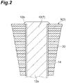
- the coil 9 is mounted on the core 12 by a bobbin 14.
- the bobbin 14 has a tubular shape.
- the bobbin 14 is a member that has an electrical insulation property, and is formed of, for instance, nylon, nylon containing fiberglass, a polybutylene terephthalate resin, a polyethylene terephthalate resin, an ABS resin, a polyamide resin, a polyphenylene sulfide resin, a liquid crystal polyester resin, or the like.
- the bobbin 14 is fitted around the core 12, and an upper end thereof is seized by the flange part 12b of the core 12. Thereby, the bobbin 14 is prevented from escaping from the core 12.
- the coil section 20 of the coil 9 is mounted on the core 12 such that one side thereof having a small width dimension is located at the base end side of the core 12. That is, the width dimension of the coil section 20 gradually increases toward a tip side of the core 12.
- the space factor is, for instance, higher than or equal to 90%.
- the motor has a smaller torque ripple in the case in which the distortion factor is small (the ratio of the harmonic component is small, and the distortion of the sine wave is small) than in the case in which the distortion factor is great (the ratio of the harmonic component is great, and the sine wave is distorted).
- the motor 1A it is confirmed that, in comparison with the coil configured by the concentrical winding of the enamel wire, a variation in torque caused by the torque ripple is small, and the rotation is smooth. Thereby, even in a low rotation region, the rotor 5A is smoothly rotated. This result is similarly obtained in the motor 1 (the outer rotor type).
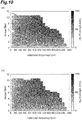
- FIG. 10 is a diagram illustrating a relationship (hereinafter referred to as "efficiency map") of motor efficiency to rotational frequency and torque of the motor 1A according to the present embodiment.
- FIG. 11 is a diagram illustrating an efficiency map of the motor according to the comparative example.
- the efficiency maps shown in FIGS. 10 and 11 are measured with a reducer connected to the motor. For this reason, in the efficiency maps shown in FIGS. 10 and 11 , the rotational frequency of the motor is 1/4 times, and the torque is four times.
- FIGS. 10(a) and 11(a) illustrate the efficiency map of a case measured at room temperature
- FIGS. 10(b) and 11(b) illustrate the efficiency map of a case measured at a high temperature (60°C).
- the insulating film 24 is formed by dip coating or electrodeposition coating. Thereby, the insulating film 24 can be formed well on the surface 21a of the conductive member 21.
- the coil section 20 is formed by joining the plurality of conductive members 21. Thereby, a desired shape of the coil section 20 can be easily formed. For this reason, the formation of a gap between the core 12 and the coil section 20 can be suppressed. As a result, the space factor of the coil 9 can be enhanced.
- the cross-sectional area of the conductive member 21 on the plane orthogonal to the extending direction of the conductive member 21 is uniform throughout the circumference of the coil section 20. Thereby, a value of electrical resistance becomes constant in the coil section 20. For this reason, the performance of the coil 9 can be improved.
- the configuration in which the plurality of conductive members 21 are joined to form the coil 9 has been described by way of example.
- the method of forming the coil 9 is not limited thereto.
- the configuration in which the coil section 20 is formed by joining the first portion 20a of a linear shape and the second portion 20b of a linear shape has been described by way of example.
- the formation of the coil section 20 is not limited to the junction between the first and second portions 20a and 20b of the linear shapes.
- the coil section 20 may be formed by joining first and second portions having other shapes.
- the configuration in which the insulating film 24 is formed by dip coating or electrodeposition coating has been described by way of example.
- the method of forming the insulating film 24 is not limited thereto.
Landscapes
- Engineering & Computer Science (AREA)
- Power Engineering (AREA)
- Manufacturing & Machinery (AREA)
- Insulation, Fastening Of Motor, Generator Windings (AREA)
- Windings For Motors And Generators (AREA)
Applications Claiming Priority (2)
| Application Number | Priority Date | Filing Date | Title |
|---|---|---|---|
| JP2015023554 | 2015-02-09 | ||
| PCT/JP2016/053529 WO2016129525A1 (fr) | 2015-02-09 | 2016-02-05 | Machine électrique rotative, bobine et dispositif de bobine |
Publications (2)
| Publication Number | Publication Date |
|---|---|
| EP3258574A1 true EP3258574A1 (fr) | 2017-12-20 |
| EP3258574A4 EP3258574A4 (fr) | 2018-09-12 |
Family
ID=56688522
Family Applications (1)
| Application Number | Title | Priority Date | Filing Date |
|---|---|---|---|
| EP16749169.5A Withdrawn EP3258574A4 (fr) | 2015-02-09 | 2016-02-05 | Machine électrique rotative, bobine et dispositif de bobine |
Country Status (5)
| Country | Link |
|---|---|
| US (1) | US20180041087A1 (fr) |
| EP (1) | EP3258574A4 (fr) |
| JP (1) | JP2016149930A (fr) |
| CN (1) | CN107210636A (fr) |
| TW (1) | TW201637327A (fr) |
Cited By (5)
| Publication number | Priority date | Publication date | Assignee | Title |
|---|---|---|---|---|
| CN108923703A (zh) * | 2018-07-25 | 2018-11-30 | 江苏大学 | 一种基于损耗调节的高效率区移动方法 |
| EP3742587A4 (fr) * | 2018-02-08 | 2021-10-13 | Aster Co., Ltd. | Unité de bobine, élément de stator, stator, moteur et procédé de fabrication pour unité de bobine, élément de stator, stator et moteur |
| EP3863154A4 (fr) * | 2018-10-02 | 2021-11-24 | Panasonic Intellectual Property Management Co., Ltd. | Stator et moteur l'utilisant |
| EP4383524A1 (fr) * | 2022-12-07 | 2024-06-12 | Fukuta Electric & Machinery Co., Ltd. | Stator de moteur |
| WO2026057883A1 (fr) | 2024-09-16 | 2026-03-19 | Sonceboz Mechatronics Boncourt Sa | Dispositif d'entrainement à assemblage facilité |
Families Citing this family (10)
| Publication number | Priority date | Publication date | Assignee | Title |
|---|---|---|---|---|
| KR20180028454A (ko) * | 2015-07-09 | 2018-03-16 | 스미토모 세이카 가부시키가이샤 | 내부분방전용 전기 절연 수지 조성물 |
| CN109478813B (zh) * | 2017-01-27 | 2021-04-06 | 株式会社日立产机系统 | 轴向间隙型旋转电机 |
| US11489387B2 (en) | 2017-04-13 | 2022-11-01 | Panasonic Intellectual Property Management Co., Ltd. | Coil and motor using same |
| TWI656712B (zh) * | 2018-06-13 | 2019-04-11 | 東元電機股份有限公司 | 馬達繞線結構 |
| US11811282B2 (en) * | 2018-10-18 | 2023-11-07 | Panasonic Intellectual Property Management Co., Ltd. | Coil device having a core with plate shaped coil bodies |
| CN109378957B (zh) * | 2018-12-22 | 2024-07-09 | 山东唐骏欧铃汽车制造有限公司 | 一种发动机直驱飞轮式发电机 |
| DE102019202236A1 (de) * | 2019-02-19 | 2020-08-20 | Fraunhofer-Gesellschaft zur Förderung der angewandten Forschung e.V. | Verfahren zum Herstellen eines wendelförmigen Metallkörpers |
| JP2020171096A (ja) * | 2019-04-02 | 2020-10-15 | 株式会社Ihi | ステータ |
| JP7334558B2 (ja) * | 2019-09-25 | 2023-08-29 | 株式会社村田製作所 | インダクタ部品 |
| EP4383525A1 (fr) * | 2022-12-09 | 2024-06-12 | Fukuta Electric & Machinery Co., Ltd. | Bobine de moteur et stator de moteur |
Family Cites Families (6)
| Publication number | Priority date | Publication date | Assignee | Title |
|---|---|---|---|---|
| JP2006158024A (ja) * | 2004-11-26 | 2006-06-15 | Sumitomo Electric Ind Ltd | コイル及びその製造方法 |
| JP2007295697A (ja) * | 2006-04-24 | 2007-11-08 | Toyota Motor Corp | 回転電機の固定子および固定子に用いられる部品 |
| JP5252807B2 (ja) * | 2006-04-28 | 2013-07-31 | 三菱電線工業株式会社 | 線状部材 |
| EP2112744A1 (fr) * | 2008-04-24 | 2009-10-28 | Magneti Marelli Holding S.p.A. | Machine synchrone polyphasée pour convertir l'énergie cinétique en énergie électrique et l'énergie électrique en une énergie cinétique à bord d'un véhicule de transport, et véhicule de transport comprenant cette machine électrique |
| DK2362526T3 (da) * | 2010-02-26 | 2014-05-05 | Siemens Ag | Fremgangsmåde til fremstilling af en stator til en energiomdannelsesindretning |
| DE102013212087C5 (de) * | 2013-06-25 | 2019-12-12 | Breuckmann GmbH & Co. KG | Verfahren zur Herstellung einer Spule |
-
2016
- 2016-02-05 EP EP16749169.5A patent/EP3258574A4/fr not_active Withdrawn
- 2016-02-05 US US15/549,592 patent/US20180041087A1/en not_active Abandoned
- 2016-02-05 JP JP2016020470A patent/JP2016149930A/ja active Pending
- 2016-02-05 CN CN201680009288.6A patent/CN107210636A/zh active Pending
- 2016-02-15 TW TW105104219A patent/TW201637327A/zh unknown
Cited By (9)
| Publication number | Priority date | Publication date | Assignee | Title |
|---|---|---|---|---|
| EP3742587A4 (fr) * | 2018-02-08 | 2021-10-13 | Aster Co., Ltd. | Unité de bobine, élément de stator, stator, moteur et procédé de fabrication pour unité de bobine, élément de stator, stator et moteur |
| US12199483B2 (en) | 2018-02-08 | 2025-01-14 | Aster Co., Ltd. | Coil unit, stator member, stator, motor, and manufacturing method for coil unit, stator member, stator, and motor |
| CN108923703A (zh) * | 2018-07-25 | 2018-11-30 | 江苏大学 | 一种基于损耗调节的高效率区移动方法 |
| CN108923703B (zh) * | 2018-07-25 | 2021-07-20 | 江苏大学 | 一种基于损耗调节的高效率区移动方法 |
| EP3863154A4 (fr) * | 2018-10-02 | 2021-11-24 | Panasonic Intellectual Property Management Co., Ltd. | Stator et moteur l'utilisant |
| US12095325B2 (en) | 2018-10-02 | 2024-09-17 | Panasonic Intellectual Property Management Co., Ltd. | Stator and motor using same |
| EP4383524A1 (fr) * | 2022-12-07 | 2024-06-12 | Fukuta Electric & Machinery Co., Ltd. | Stator de moteur |
| WO2026057883A1 (fr) | 2024-09-16 | 2026-03-19 | Sonceboz Mechatronics Boncourt Sa | Dispositif d'entrainement à assemblage facilité |
| FR3166497A1 (fr) * | 2024-09-16 | 2026-03-20 | Sonceboz Mechatronics Boncourt Sa | Dispositif d’entrainement à assemblage facilité |
Also Published As
| Publication number | Publication date |
|---|---|
| JP2016149930A (ja) | 2016-08-18 |
| CN107210636A (zh) | 2017-09-26 |
| TW201637327A (zh) | 2016-10-16 |
| EP3258574A4 (fr) | 2018-09-12 |
| US20180041087A1 (en) | 2018-02-08 |
Similar Documents
| Publication | Publication Date | Title |
|---|---|---|
| EP3258574A1 (fr) | Machine électrique rotative, bobine et dispositif de bobine | |
| US11075556B2 (en) | Coreless electric machine with magnet coils with effective coil part and end coil parts | |
| US8614617B2 (en) | Reactor | |
| CN103929000B (zh) | 用于旋转电机绕组的集合导线和旋转电机 | |
| US11152828B2 (en) | Rotating electric machine | |
| JP5214064B2 (ja) | インバータ一体型駆動モジュール | |
| US11063486B2 (en) | Coreless electric machine with magnet coils having trapezoidal shape and angle less than 90 degrees with circumferentially aligned legs | |
| US20170237304A1 (en) | Stator for rotary electric machine | |
| JP2013215021A (ja) | 電磁誘導装置 | |
| JP2015133772A (ja) | バスバーモジュールおよび回転電機 | |
| CN113039704A (zh) | 定子及使用该定子的电动机 | |
| JP5399317B2 (ja) | リアクトル | |
| JP2015223028A (ja) | 回転電機用のステータ | |
| KR20160086698A (ko) | 모터의 스테이터 어셈블리 | |
| KR102342560B1 (ko) | 회전전기기기의 스테이터 | |
| US20190035548A1 (en) | Laminated core rotatable transformer | |
| CN112789785B (zh) | 带有环形线圈以及曲折的线圈的爪极电动机 | |
| JP2015027208A (ja) | 電磁誘導装置 | |
| JP2014054092A (ja) | アキシャルギャップ型ブラシレスモータ | |
| US20230208238A1 (en) | Electric drive for a vehicle | |
| JP6394542B2 (ja) | 回転電機ステータ | |
| WO2016129525A1 (fr) | Machine électrique rotative, bobine et dispositif de bobine | |
| JP2015082952A (ja) | 回転電機用のステータ及びコイルの絶縁膜形成方法 | |
| US20200136457A1 (en) | Stator of rotating electric apparatus | |
| KR102068566B1 (ko) | 모터 |
Legal Events
| Date | Code | Title | Description |
|---|---|---|---|
| PUAI | Public reference made under article 153(3) epc to a published international application that has entered the european phase |
Free format text: ORIGINAL CODE: 0009012 |
|
| 17P | Request for examination filed |
Effective date: 20170905 |
|
| AK | Designated contracting states |
Kind code of ref document: A1 Designated state(s): AL AT BE BG CH CY CZ DE DK EE ES FI FR GB GR HR HU IE IS IT LI LT LU LV MC MK MT NL NO PL PT RO RS SE SI SK SM TR |
|
| AX | Request for extension of the european patent |
Extension state: BA ME |
|
| DAV | Request for validation of the european patent (deleted) | ||
| DAX | Request for extension of the european patent (deleted) | ||
| RIC1 | Information provided on ipc code assigned before grant |
Ipc: H02K 1/14 20060101ALN20180802BHEP Ipc: H02K 3/34 20060101ALN20180802BHEP Ipc: H02K 15/04 20060101ALI20180802BHEP Ipc: H02K 29/03 20060101ALN20180802BHEP Ipc: H02K 3/18 20060101AFI20180802BHEP Ipc: H02K 21/16 20060101ALN20180802BHEP Ipc: H02K 1/27 20060101ALN20180802BHEP |
|
| A4 | Supplementary search report drawn up and despatched |
Effective date: 20180809 |
|
| STAA | Information on the status of an ep patent application or granted ep patent |
Free format text: STATUS: THE APPLICATION IS DEEMED TO BE WITHDRAWN |
|
| 18D | Application deemed to be withdrawn |
Effective date: 20190308 |