EP3258587B1 - Drehzahlvariable leistungsregelung mit konstanter frequenz - Google Patents
Drehzahlvariable leistungsregelung mit konstanter frequenz Download PDFInfo
- Publication number
- EP3258587B1 EP3258587B1 EP17174956.7A EP17174956A EP3258587B1 EP 3258587 B1 EP3258587 B1 EP 3258587B1 EP 17174956 A EP17174956 A EP 17174956A EP 3258587 B1 EP3258587 B1 EP 3258587B1
- Authority
- EP
- European Patent Office
- Prior art keywords
- control
- inverter
- vscf
- generator
- power converter
- Prior art date
- Legal status (The legal status is an assumption and is not a legal conclusion. Google has not performed a legal analysis and makes no representation as to the accuracy of the status listed.)
- Active
Links
Images


Classifications
-
- H—ELECTRICITY
- H02—GENERATION; CONVERSION OR DISTRIBUTION OF ELECTRIC POWER
- H02H—EMERGENCY PROTECTIVE CIRCUIT ARRANGEMENTS
- H02H7/00—Emergency protective circuit arrangements specially adapted for specific types of electric machines or apparatus or for sectionalised protection of cable or line systems, and effecting automatic switching in the event of an undesired change from normal working conditions
- H02H7/06—Emergency protective circuit arrangements specially adapted for specific types of electric machines or apparatus or for sectionalised protection of cable or line systems, and effecting automatic switching in the event of an undesired change from normal working conditions for dynamo-electric generators; for synchronous capacitors
-
- H—ELECTRICITY
- H02—GENERATION; CONVERSION OR DISTRIBUTION OF ELECTRIC POWER
- H02M—APPARATUS FOR CONVERSION BETWEEN AC AND AC, BETWEEN AC AND DC, OR BETWEEN DC AND DC, AND FOR USE WITH MAINS OR SIMILAR POWER SUPPLY SYSTEMS; CONVERSION OF DC OR AC INPUT POWER INTO SURGE OUTPUT POWER; CONTROL OR REGULATION THEREOF
- H02M5/00—Conversion of AC power input into AC power output, e.g. for change of voltage, for change of frequency, for change of number of phases
- H02M5/40—Conversion of AC power input into AC power output, e.g. for change of voltage, for change of frequency, for change of number of phases with intermediate conversion into DC
- H02M5/42—Conversion of AC power input into AC power output, e.g. for change of voltage, for change of frequency, for change of number of phases with intermediate conversion into DC by static converters
- H02M5/44—Conversion of AC power input into AC power output, e.g. for change of voltage, for change of frequency, for change of number of phases with intermediate conversion into DC by static converters using discharge tubes or semiconductor devices to convert the intermediate DC into AC
- H02M5/453—Conversion of AC power input into AC power output, e.g. for change of voltage, for change of frequency, for change of number of phases with intermediate conversion into DC by static converters using discharge tubes or semiconductor devices to convert the intermediate DC into AC using devices of a triode or transistor type requiring continuous application of a control signal
- H02M5/458—Conversion of AC power input into AC power output, e.g. for change of voltage, for change of frequency, for change of number of phases with intermediate conversion into DC by static converters using discharge tubes or semiconductor devices to convert the intermediate DC into AC using devices of a triode or transistor type requiring continuous application of a control signal using semiconductor devices only
-
- B—PERFORMING OPERATIONS; TRANSPORTING
- B60—VEHICLES IN GENERAL
- B60R—VEHICLES, VEHICLE FITTINGS, OR VEHICLE PARTS, NOT OTHERWISE PROVIDED FOR
- B60R16/00—Electric or fluid circuits specially adapted for vehicles and not otherwise provided for; Arrangement of elements of electric or fluid circuits specially adapted for vehicles and not otherwise provided for
- B60R16/02—Electric or fluid circuits specially adapted for vehicles and not otherwise provided for; Arrangement of elements of electric or fluid circuits specially adapted for vehicles and not otherwise provided for electric constitutive elements
- B60R16/03—Electric or fluid circuits specially adapted for vehicles and not otherwise provided for; Arrangement of elements of electric or fluid circuits specially adapted for vehicles and not otherwise provided for electric constitutive elements for supply of electrical power to vehicle subsystems or for
-
- B—PERFORMING OPERATIONS; TRANSPORTING
- B64—AIRCRAFT; AVIATION; COSMONAUTICS
- B64D—EQUIPMENT FOR FITTING IN OR TO AIRCRAFT; FLIGHT SUITS; PARACHUTES; ARRANGEMENT OR MOUNTING OF POWER PLANTS OR PROPULSION TRANSMISSIONS IN AIRCRAFT
- B64D41/00—Power installations for auxiliary purposes
-
- H—ELECTRICITY
- H02—GENERATION; CONVERSION OR DISTRIBUTION OF ELECTRIC POWER
- H02H—EMERGENCY PROTECTIVE CIRCUIT ARRANGEMENTS
- H02H7/00—Emergency protective circuit arrangements specially adapted for specific types of electric machines or apparatus or for sectionalised protection of cable or line systems, and effecting automatic switching in the event of an undesired change from normal working conditions
- H02H7/10—Emergency protective circuit arrangements specially adapted for specific types of electric machines or apparatus or for sectionalised protection of cable or line systems, and effecting automatic switching in the event of an undesired change from normal working conditions for converters; for rectifiers
- H02H7/12—Emergency protective circuit arrangements specially adapted for specific types of electric machines or apparatus or for sectionalised protection of cable or line systems, and effecting automatic switching in the event of an undesired change from normal working conditions for converters; for rectifiers for static converters or rectifiers
- H02H7/122—Emergency protective circuit arrangements specially adapted for specific types of electric machines or apparatus or for sectionalised protection of cable or line systems, and effecting automatic switching in the event of an undesired change from normal working conditions for converters; for rectifiers for static converters or rectifiers for inverters, i.e. DC/AC converters
-
- H—ELECTRICITY
- H02—GENERATION; CONVERSION OR DISTRIBUTION OF ELECTRIC POWER
- H02P—CONTROL OR REGULATION OF ELECTRIC MOTORS, ELECTRIC GENERATORS OR DYNAMO-ELECTRIC CONVERTERS; CONTROLLING TRANSFORMERS, REACTORS OR CHOKE COILS
- H02P9/00—Arrangements for controlling electric generators for the purpose of obtaining a desired output
- H02P9/006—Means for protecting the generator by using control
-
- H—ELECTRICITY
- H02—GENERATION; CONVERSION OR DISTRIBUTION OF ELECTRIC POWER
- H02P—CONTROL OR REGULATION OF ELECTRIC MOTORS, ELECTRIC GENERATORS OR DYNAMO-ELECTRIC CONVERTERS; CONTROLLING TRANSFORMERS, REACTORS OR CHOKE COILS
- H02P9/00—Arrangements for controlling electric generators for the purpose of obtaining a desired output
- H02P9/10—Control effected upon generator excitation circuit to reduce harmful effects of overloads or transients, e.g. sudden application of load, sudden removal of load, sudden change of load
-
- H—ELECTRICITY
- H02—GENERATION; CONVERSION OR DISTRIBUTION OF ELECTRIC POWER
- H02P—CONTROL OR REGULATION OF ELECTRIC MOTORS, ELECTRIC GENERATORS OR DYNAMO-ELECTRIC CONVERTERS; CONTROLLING TRANSFORMERS, REACTORS OR CHOKE COILS
- H02P9/00—Arrangements for controlling electric generators for the purpose of obtaining a desired output
- H02P9/14—Arrangements for controlling electric generators for the purpose of obtaining a desired output by variation of field
- H02P9/26—Arrangements for controlling electric generators for the purpose of obtaining a desired output by variation of field using discharge tubes or semiconductor devices
- H02P9/30—Arrangements for controlling electric generators for the purpose of obtaining a desired output by variation of field using discharge tubes or semiconductor devices using semiconductor devices
- H02P9/305—Arrangements for controlling electric generators for the purpose of obtaining a desired output by variation of field using discharge tubes or semiconductor devices using semiconductor devices controlling voltage
-
- B—PERFORMING OPERATIONS; TRANSPORTING
- B64—AIRCRAFT; AVIATION; COSMONAUTICS
- B64D—EQUIPMENT FOR FITTING IN OR TO AIRCRAFT; FLIGHT SUITS; PARACHUTES; ARRANGEMENT OR MOUNTING OF POWER PLANTS OR PROPULSION TRANSMISSIONS IN AIRCRAFT
- B64D2221/00—Electric power distribution systems onboard aircraft
-
- H—ELECTRICITY
- H02—GENERATION; CONVERSION OR DISTRIBUTION OF ELECTRIC POWER
- H02P—CONTROL OR REGULATION OF ELECTRIC MOTORS, ELECTRIC GENERATORS OR DYNAMO-ELECTRIC CONVERTERS; CONTROLLING TRANSFORMERS, REACTORS OR CHOKE COILS
- H02P2101/00—Special adaptation of control arrangements for generators
- H02P2101/30—Special adaptation of control arrangements for generators for aircraft
Definitions
- This disclosure relates to a variable-speed constant-frequency, (VSCF), power converter and a method to control such a converter.
- VSCF variable-speed constant-frequency
- aircraft To produce electric power, aircraft typically use generators coupled to engines located on the wings. Different types of generators have been used that have varying levels of complexity and output power characteristics. Aircraft engines are normally used over a wide range of operating conditions in the air, including takeoff, cruise, descent, and landing. This demands that the engines operate over a range of rotating speeds. Previous generators required constant speed inputs for producing power and use mechanisms including constant speed drives and integrated drive generators. Such devices include heavy hydro-mechanical devices that are coupled to an input shaft rotating at varying input speeds (indexed to the engine speed) and deliver power to an output shaft that rotates at a constant speed, despite the varying input. The heavy hydro-mechanical devices may add unwanted loads to the wings of the aircraft.
- VFGs variable frequency generators
- control electronics typically employ static switch timing. Tightly coupled control of the VFG with power conversion control may increase the risk of faults or component defects producing abnormally high generator output voltages and/or other performance issues.
- US 4937 723A describes a VSCF system with an overload protection. Examples of the prior art describing redundant fault protection are the following: US4403292A , US5438502A , US2012/106009A1 , US9018889B2 and EP2482445A2 .
- variable-speed constant-frequency, VSCF, power converter as recited in claim 1.
- a method of controlling a VSCF power converter according to claim 8 is provided.
- a variable-speed constant-frequency (VSCF) power system is provided with independent control and monitoring of generator excitation current control, and inverter control to improve failure modes, and enhance point-of-regulation (POR) voltage power quality.
- redundancy and independent voltage control, monitoring, and protection functions provide separate control paths for both generator and inverter power controls as series elements.
- the control topologies described herein may have dissimilar and independent voltage control and protection functions to provide robust failure response to meet the needs of high integrity (e.g., flight safety) aircraft equipment.
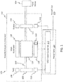
- the VSCF power generating system 100 includes variable frequency generator (VFG) 102 that is driven by rotation of a prime mover 104, such as an aircraft engine operating a various speeds.
- VFG 102 includes a permanent magnet generator (PMG) 106 that comprises a rotating portion 108 and a stationary portion 110.
- the PMG 106 can include a plurality of permanent magnets and phase windings (not depicted) distributed between the rotating portion 108 and the stationary portion 110 to induce an electric current in response to the prime mover 104 driving the rotating portion 108 to rotate proximate to the stationary portion 110.
- a voltage produced by the PMG 106 can be output to a VSCF power converter 112, which may be a unit within a power panel 114 of an aircraft (e.g., within an aircraft fuselage).
- the voltage from the PMG 106 can be used to power control circuitry within the VSCF power converter 112.
- the VSCF power converter 112 controls an exciter 116 of the VFG 102 and regulates an output voltage of a main generator 118 of the VFG 102 at a variable frequency for an aircraft use 120.
- the exciter 116 includes a rotating portion 122 and a stationary portion 124.
- the main generator 118 includes a rotating portion 126 and a stationary portion 128.
- the rotation portion 108 of the PMG 106, the rotating portion 122 of the exciter 116, and the rotating portion 126 of the main generator 118 can all be coupled to a common shaft 130 in one or more segments driven by rotation of the prime mover 104 at varying speeds.
- the rotating portion 122 of the exciter 116 is electrically coupled to the rotating portion 126 of the main generator 118.
- the VSCF power converter 112 controls an exciter current provided to the exciter 116, which can adjust the field strength of the main generator 118 to regulate an output voltage of the VFG 102 at stationary portion 128.
- Various sensors such as a generator current sensor 132, can also be included for control and fault detection by the VSCF power converter 112.
- the VSCF power converter 112 of FIG. 1 includes a generator control 202 operable to regulate an output voltage of the VFG 102 at a variable frequency on feeder lines 204.
- the output voltage of the VFG 102 can be multi-phase (e.g., three or more phases) depending on the winding configuration used in the VFG 102.
- the generator control 202 can interface with the VFG 102 over multiple signal lines 206, for instance, to receive a PMG voltage from the PMG 106, source an exciter current to the exciter 116, and receive a sensed generator current from the generator current sensor 132 of the main generator 118.
- the VSCF power converter 112 also includes an inverter control 208 operable to regulate a VSCF output voltage at a point-of-regulation 210 at a constant frequency.
- the generator control 202 and the inverter control 208 independently control a main line contactor 212 (e.g., a breaker) of the point-of-regulation 210 to provide redundant fault protection for the aircraft use 120.
- the generator control 202 and the inverter control 208 can act as series controls, where the generator control 202 monitors sensed inputs 214 indicative of a voltage and current output by the VFG 102 and actively adjusts the exciter current to regulate the output voltage of the VFG 102 within a predetermined range.
- the inverter control 208 also monitors sensed inputs 214 indicative of the voltage and current output by the VFG 102 and actively adjusts gate drive timing of an inverter 216 to regulate the output voltage at the point-of-regulation 210.
- the VSCF power converter 112 can also include a filter 218 to adjust power quality and filter electromagnetic interference of multi-phase output voltage of the VFG 102.
- a rectifier 220 e.g., a multi-pulse rectifier
- filter 222 perform alternating current (AC) to direct current (DC) conversion and signal conditioning.
- the inverter control 208 can perform DC link voltage and current sensing 224 at a DC link between the filter 222 and inverter 216.
- the inverter control 208 can also perform voltage and current sensing 226 at one or more outputs of the inverter 216.
- the inverter 216 can include various architectures, such as a 2-level, 3-level, 3-legged with neutral forming transformer, 4-legged inverter to eliminate a heavy autotransformer, and/or other architectures known in the art.
- a filter 228 between the inverter 216 and point-of-regulation 210 can adjust power quality and filter electromagnetic interference of the constant frequency output of the VSCF power converter 112.
- Point-of-regulation status (e.g., voltage and current) as well as main line contactor status can be provided on lines 230 from the point-of-regulation 210 and main line contactor 212 to the generator control 202 and the inverter control 208. If the lines 230 between the inverter control 208 and the point-of-regulation 210 and/or main line contactor 212 experience a fault or sustain damage, the generator control 202 can relay the information redundantly on line 232 as a backup. Lines 232 can be used to provide the inverter control 208 with redundant point-of-regulation status, to command enablement of the inverter control 208, and provide a power ready indication from the generator control 202 when the output of the VFG 204 is ready to use.
- Lines 232 can be used to provide the inverter control 208 with redundant point-of-regulation status, to command enablement of the inverter control 208, and provide a power ready indication from the generator control 202 when the output of the VFG 204 is ready to use.
- the inverter control 208 can monitor temperature and faults in the inverter 216 and may dynamically adjust gate drive timing on lines 234 to the inverter 216 based on a required POR voltage, a DC conversion of the output voltage of the VFG 102 at a DC link and one or more outputs of the inverter 216. For instance, an amount of over or under voltage may be accommodated by adjusting gate drive timing (e.g., pulse width modulation timing) to the inverter 216.
- the inverter control 208 can provide an inverter status, inverter faults, load faults, and/or other information to the generator control 202 on lines 236.
- faults detected by or received at the generator control 202 result in the generator control 202 inhibiting excitation power to prevent conditions such as over excitation or over/under frequency conditions, for example.
- the generator control 202 can open the main line contactor 212 to prevent a fault from propagating to the aircraft use 120 for an extended period of time.
- the inverter control 208 can open the main line contactor 212 if the inverter control 208 is unable to accommodate the fault.
- the generator control 202 and the inverter control 208 can be implemented as separate modules of the VSCF power converter 112.
- the term "module” refers to an application specific integrated circuit (ASIC), an electronic circuit, an electronic computer processor (shared, dedicated, or group) and memory that executes one or more software or firmware programs, a combinational logic circuit, and/or other suitable components that provide the described functionality.
- ASIC application specific integrated circuit
- a module can be embodied in memory as a non-transitory machine-readable storage medium readable by a processing circuit and storing instructions for execution by the processing circuit for performing a method.
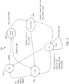
- FIG. 3 depicts an example of a state transition diagram 300 that can be implemented within the generator control 202 of FIG. 2 .
- the generator control 202 operates functionally independent of the inverter control 208 of FIG. 2 , but signals generated by the generator control 202 can trigger transitions of the inverter control 208 and signals from the inverter control 208 can trigger transitions of the generator control 202.
- the generator control 202 is initially in an off state 302 and upon a reset, performs a health check 304.
- the health check 304 can include built-in checks of the generator control 202 and its associated hardware.
- the health check 304 can include monitoring values on signal lines 206 of FIG.
- the channel e.g., system executing generator control 202
- the generator control 202 can output a status report (e.g., to a maintenance system) before transitioning to the off state 302.
- the generator control 202 can indicate that generator power is ready and transition to GC enable state 308.
- the generator power ready indication can be sent on lines 232 to the inverter control 208 along with an inverter enable signal and currently sensed POR value.
- the generator control 202 can transition from the GC enable state 308 to assert fault 306. If the generator control 202 receives an inverter status ok indication from the inverter control 208 and determines that POR power is ready based on values from lines 230, the generator control 202 transitions to an on state 310. In the on state 310, an MLC control command can be output from the generator control 202 on lines 230. If a generator wiring fault, load fault (e.g., from aircraft use 120), inverter fault, or POR fault is detected, the generator control 202 can assert a fault 306.
- FIG. 4 depicts an example of a state transition diagram 400 that can be implemented within the inverter control 208 of FIG. 2 .
- the inverter control 208 is initially in an off state 402 and upon an inverter enable and generator power ready indication from the generator control 202 on lines 232, the inverter control 208 can perform a health check 404.
- the health check 404 can include checks of the inverter 216 and its associated wiring.
- the health check 404 can include monitoring values on signal lines 214, 224, 226, and 234 of FIG. 2 . If an inverter or wiring fault is detected at the health check 404, a fault 406 is asserted.
- the inverter control 208 can output a status report (e.g., to a maintenance system) before transitioning to the off state 402. If the health check 404 is successful, the inverter control 208 can transition to inverter enable state 408 and indicate that the inverter status is ok to the generator control 202 on lines 236. If the inverter control 208 detects an inverter fault, the inverter control 208 can transition from the inverter enable state 408 to assert fault 406. If the inverter control 208 receives and/or determines that POR power is ready based on values from lines 230 and/or 232, the inverter control 208 transitions to an on state 410.
- a status report e.g., to a maintenance system
- an MLC enable command can be output from the inverter control 208 on lines 230.
- the MLC enable command from the inverter control 208 and the MLC control command from the generator control 202 can control opening and closing of the main line contactor 212 as an AND-gate function, where either the generator control 202 or the inverter control 208 can open the main line contactor 212 but both are used to close the main line contactor 212. If a load fault (e.g., from aircraft use 120), inverter fault, or POR fault is detected, the inverter control 208 can assert a fault 406.
- FIG. 5 is a flow chart illustrating a method 500 for controlling a VSCF power converter 112 in accordance with an embodiment.
- the method 500 of FIG. 5 is described in reference to FIGS. 1-4 and may be performed with an alternate order and include additional steps.
- an output voltage of a VFG 102 is regulated at a variable frequency by a generator control 202 of the VSCF power converter 112.
- a VSCF power converter output voltage is regulated at a point-of-regulation 210 at a constant frequency by an inverter control 208 of the VSCF power converter 112.
- a main line contactor 212 of the point-of-regulation 210 is independently controlled by the generator control 202 and the inverter control 208 to provide redundant fault protection for an aircraft use 120.
- the generator control 202 can adjust an exciter current of the VFG 102 to maintain the output voltage of the VFG 102 within a predetermined voltage range.
- the inverter control 208 can dynamically adjust gate drive timing to the inverter 216 based on a required POR voltage, DC conversion of the output voltage of the VFG 102 at a DC link and one or more outputs of the inverter 102.
- a redundant point-of-regulation status can be provided from the generator control 202 to the inverter control 208.
- An inverter status, inverter faults, and load faults from the inverter control 208 can be provided to the generator control 202.
- the generator control 202 can also control enablement of the inverter control 208.
- the output voltage of the VFG 102 can be a multi-phase voltage, and the VSCF output voltage may be a three phase voltage.
Landscapes
- Engineering & Computer Science (AREA)
- Power Engineering (AREA)
- Mechanical Engineering (AREA)
- Aviation & Aerospace Engineering (AREA)
- Control Of Eletrric Generators (AREA)
Claims (13)
- Stromrichter (112) mit konstanter Frequenz bei variabler Drehzahl (variable-speed constant-Frequenz - VSCF), der so ausgelegt ist, dass er Leistung von einem Generator mit variabler Frequenz (variable Frequenz generator - VFG) (102) aufnimmt und ein Hauptleitungsschütz (212) eines Regulierungspunkts (210) steuert, wobei der VSCF-Stromrichter Folgendes umfasst:eine Generatorsteuerung (202), die so betrieben werden kann, dass sie eine Ausgangsspannung des VFG mit einer variablen Frequenz regelt; undeine Invertersteuerung (208), die so betrieben werden kann, dass sie eine VSCF-Ausgangsspannung an dem Regulierungspunkt mit einer konstanten Frequenz regelt, und dadurch gekennzeichnet, dass die Generatorsteuerung (202) und die Invertersteuerung (208) so konfiguriert sind, dass siedas Hauptleitungsschütz des Regulierungspunkts unabhängig als eine UND-Gate-Funktion steuern, um einen redundanten Fehlerschutz für eine Luftfahrzeugverwendung bereitzustellen, wobei der VSCF-Stromrichter so konfiguriert ist, dass er das Hauptleitungsschütz bei einem Befehl entweder der Generatorsteuerung (202) oder der Invertersteuerung (208) öffnet, und das Hauptleitungsschütz bei einem Befehl sowohl der Generatorsteuerung (202) als auch der Invertersteuerung (208) schließt.
- VSCF-Stromrichter nach Anspruch 1, wobei die Generatorsteuerung (202) so konfiguriert ist, dass sie einen Erregerstrom des VFG so anpasst, dass die Ausgangsspannung des VFG innerhalb eines vorbestimmten Spannungsbereichs gehalten wird.
- VSCF-Stromrichter nach Anspruch 2, wobei die Invertersteuerung (208) so konfiguriert ist, dass sie eine Gate-Ansteuerungszeitsteuerung zu einem Inverter basierend auf einer Gleichstrom(direct current - DC)-Umwandlung der Ausgangsspannung des VFG an einem Zwischenkreis und einem oder mehreren Ausgängen des Inverters dynamisch anpasst.
- VSCF-Stromrichter nach einem der vorstehenden Ansprüche, wobei die Generatorsteuerung (202) so konfiguriert ist, dass sie einen redundanten Regulierungspunktstatus für die Invertersteuerung (208) als eine Sicherung im Fall eines Fehlers oder eines Schadens an einer oder mehreren Leitungen, die einen Regulierungspunktstatus zwischen dem Regulierungspunkt und der Invertersteuerung (208) bereitstellen, bereitstellt.
- VSCF-Stromrichter nach Anspruch 4, wobei die Invertersteuerung (208) so konfiguriert ist, dass sie einen Inverterstatus, Inverterfehler und Lastfehler für die Generatorsteuerung bereitstellt.
- VSCF-Stromrichter nach einem der vorstehenden Ansprüche, wobei die Generatorsteuerung (202) so konfiguriert ist, dass sie die Aktivierung der Invertersteuerung befiehlt.
- VSCF-Stromrichter nach einem der vorstehenden Ansprüche, wobei die Ausgangsspannung des VFG eine Mehrphasenspannung ist und die VSCF-Ausgangsspannung eine Dreiphasenspannung ist.
- Verfahren zum Steuern eines Stromrichter (112) mit konstanter Frequenz bei variabler Drehzahl (variable-speed constant-Frequenz - VSCF), der so ausgelegt ist, dass er Leistung von einem Generator mit variabler Frequenz (variable Frequenz generator - VFG) (102) aufnimmt und ein Hauptleitungsschütz (212) eines Regulierungspunkts (210) steuert, der VSCF-Stromrichter, wobei das Verfahren Folgendes umfasst:Regeln einer Ausgangsspannung des VFG mit einer variablen Frequenz durch eine Generatorsteuerung des VSCF-Stromrichters;Regeln einer VSCF-Stromrichter-Ausgangsspannung an dem Regulierungspunkt mit einer konstanten Frequenz durch eine Invertersteuerung des VSCF-Stromrichters; und gekennzeichnet durchunabhängiges Steuern des Hauptleitungsschützes des Regulierungspunkts durch die Generatorsteuerung (202) und die Invertersteuerung (208) als eine UND-Gate-Funktion, um einen redundanten Fehlerschutz für eine Luftfahrzeugverwendung bereitzustellen, wobei das Hauptleitungsschütz als Reaktion auf entweder die Generatorsteuerung (202) oder die Invertersteuerung (208) geöffnet wird, und das Hauptleitungsschütz geschlossen wird, wenn dies sowohl von der Generatorsteuerung (202) als auch der Invertersteuerung (208) befohlen wird.
- Verfahren nach Anspruch 8, ferner Folgendes umfassend:
Anpassen, durch die Generatorsteuerung (202), eines Erregerstroms des VFG so, dass die Ausgangsspannung des VFG innerhalb eines vorbestimmten Spannungsbereichs gehalten wird. - Verfahren nach Anspruch 9, ferner Folgendes umfassend:
dynamisches Anpassen, durch die Invertersteuerung (208), einer Gate-Ansteuerungszeitsteuerung zu einem Inverter basierend auf einer erforderlichen Regulierungspunktspannung, einer Gleichstrom(direct current - DC)-Umwandlung der Ausgangsspannung des VFG an einem Zwischenkreis und einem oder mehreren Ausgängen des Inverters. - Verfahren nach Anspruch 8, 9 oder 10, ferner Folgendes umfassend:Bereitstellen eines redundanten Regulierungspunktstatus von der Generatorsteuerung (202) für die Invertersteuerung (208) als eine Sicherung im Fall eines Fehlers oder eines Schadens an einer oder mehreren Leitungen, die einen Regulierungspunktstatus zwischen dem Regulierungspunkt und der Invertersteuerung (208) bereitstellen,; undBereitstellen eines Inverterstatus, von Inverterfehlern und Lastfehlern von der Invertersteuerung (208) für die Generatorsteuerung (202).
- Verfahren nach einem der Ansprüche 8 bis 11, ferner das Steuern einer Aktivierung der Invertersteuerung durch die Generatorsteuerung (202) umfassend.
- Verfahren nach einem der Ansprüche 8 bis 12, wobei die Ausgangsspannung des VFG eine Mehrphasenspannung ist und die VSCF-Ausgangsspannung eine Dreiphasenspannung ist.
Applications Claiming Priority (1)
| Application Number | Priority Date | Filing Date | Title |
|---|---|---|---|
| US15/182,782 US10003186B2 (en) | 2016-06-15 | 2016-06-15 | Variable-speed constant-frequency power control |
Publications (2)
| Publication Number | Publication Date |
|---|---|
| EP3258587A1 EP3258587A1 (de) | 2017-12-20 |
| EP3258587B1 true EP3258587B1 (de) | 2021-12-08 |
Family
ID=59067494
Family Applications (1)
| Application Number | Title | Priority Date | Filing Date |
|---|---|---|---|
| EP17174956.7A Active EP3258587B1 (de) | 2016-06-15 | 2017-06-08 | Drehzahlvariable leistungsregelung mit konstanter frequenz |
Country Status (2)
| Country | Link |
|---|---|
| US (1) | US10003186B2 (de) |
| EP (1) | EP3258587B1 (de) |
Families Citing this family (11)
| Publication number | Priority date | Publication date | Assignee | Title |
|---|---|---|---|---|
| US11522412B2 (en) | 2018-05-24 | 2022-12-06 | Hamilton Sundstrand Corporation | Mounting arrangements for gas turbine engine accessories |
| CN110556785B (zh) * | 2018-05-31 | 2022-11-04 | 上海航空电器有限公司 | 单通道多电飞机发电机控制器的vfsg频率保护结构 |
| US10965125B2 (en) | 2018-07-11 | 2021-03-30 | The Boeing Company | Simultaneous bidirectional power usage of generator power feeders |
| US10746803B2 (en) | 2018-12-06 | 2020-08-18 | Hamilton Sunstrand Corporation | Fault detection and isolation in generator modules |
| US10491138B1 (en) | 2019-02-07 | 2019-11-26 | Hamilton Sundstrand Corporation | Multilevel inverters and methods of controlling multilevel inverters |
| US11502617B2 (en) | 2019-02-08 | 2022-11-15 | Hamilton Sundstrand Corporation | Generator systems and controllers |
| US10715029B1 (en) | 2019-02-08 | 2020-07-14 | Hamilton Sundstrand Corporation | Generator systems and controllers |
| US10630164B1 (en) | 2019-02-08 | 2020-04-21 | Hamilton Sundstrand Corporation | Generator systems |
| US11611287B2 (en) | 2021-02-10 | 2023-03-21 | Hamilton Sundstrand Corporation | Dual sourced common 3-level VSCF |
| US11482957B1 (en) * | 2021-08-02 | 2022-10-25 | Hamilton Sundstrand Corporation | Cascaded multiple feedback controller |
| US20240372492A1 (en) * | 2023-05-04 | 2024-11-07 | Hamilton Sundstrand Corporation | Generator control architecture |
Citations (5)
| Publication number | Priority date | Publication date | Assignee | Title |
|---|---|---|---|---|
| EP1187293A2 (de) * | 2000-08-28 | 2002-03-13 | Honda Giken Kogyo Kabushiki Kaisha | Motorgeneratorvorrichtung |
| US20080164850A1 (en) * | 2006-12-29 | 2008-07-10 | Elias Ayana | Shore power transfer switch |
| US20120106009A1 (en) * | 2010-10-28 | 2012-05-03 | Hamilton Sundstrand Corporation | Shunt Regulator at Excitation Output of Generator Control Unit for Overvoltage Protection |
| EP2482445A2 (de) * | 2011-01-28 | 2012-08-01 | Hamilton Sundstrand Corporation | Unabhängiger, redundanter Überspannungsschutz für einen Generator |
| US9018889B2 (en) * | 2012-12-18 | 2015-04-28 | Hamilton Sundstrand Corporation | Hardware-based, redundant overvoltage protection |
Family Cites Families (20)
| Publication number | Priority date | Publication date | Assignee | Title |
|---|---|---|---|---|
| US4403292A (en) | 1979-05-30 | 1983-09-06 | Sundstrand Corporation | Control for an electrical generating and distribution system, and method of operation |
| US4456830A (en) * | 1982-04-22 | 1984-06-26 | Lockheed Corporation | AC Motor-starting for aircraft engines using APU free turbine driven generators |
| US4862341A (en) * | 1988-11-02 | 1989-08-29 | Sundstrand Corporation | Filter for variable speed, constant frequency electrical system |
| WO1990006621A1 (en) | 1988-12-05 | 1990-06-14 | Sundstrand Corporation | Vscf start system with precise voltage control |
| US4956598A (en) | 1988-12-16 | 1990-09-11 | Sundstrand Corporation | Low distortion control for a VSCF generating system |
| US4937462A (en) * | 1989-01-23 | 1990-06-26 | Sundstrand Corporation | No break power transfer control for a VSCF power generating system |
| US4937723A (en) | 1989-05-15 | 1990-06-26 | Sundstrand Corporation | VSCF system with an overload protection |
| US5117174A (en) * | 1989-10-03 | 1992-05-26 | Westinghouse Electric Corp. | Electric power system with line drop compensation |
| US4937720A (en) | 1989-10-13 | 1990-06-26 | Sundstrand Corporation | PWM inverter circuit analytically compensating for DC link distortion |
| US5317500A (en) | 1992-08-06 | 1994-05-31 | Sundstrand Corporation | Active no-break power transfer control for a VSCF power generating system |
| US5438502A (en) | 1992-12-22 | 1995-08-01 | Rozman; Gregory I. | VSCF system with voltage estimation |
| US5559689A (en) * | 1994-08-08 | 1996-09-24 | Sundstrand Corporation | Harmonic content determination apparatus |
| US5798631A (en) | 1995-10-02 | 1998-08-25 | The State Of Oregon Acting By And Through The State Board Of Higher Education On Behalf Of Oregon State University | Performance optimization controller and control method for doubly-fed machines |
| US5737196A (en) * | 1996-08-12 | 1998-04-07 | Sundstrand Corporation | Electrical power generating system producing alternating and direct current |
| US6844706B2 (en) | 2002-08-30 | 2005-01-18 | Active Power, Inc. | Multiple path variable speed constant frequency device having automatic power path selection capability |
| US6778414B2 (en) | 2002-12-20 | 2004-08-17 | The Boeing Company | Distributed system and methodology of electrical power regulation, conditioning and distribution on an aircraft |
| KR100947975B1 (ko) | 2007-10-04 | 2010-03-15 | 경성대학교 산학협력단 | 직접적이고 순시적인 발전기의 여자기 제어시스템 및 방법 |
| US8039983B2 (en) * | 2008-12-02 | 2011-10-18 | The Boeing Company | Systems and methods for providing AC power from multiple turbine engine spools |
| US8829707B2 (en) * | 2010-07-15 | 2014-09-09 | Hamilton Sundstrand Corporation | Methods for aircraft emergency power management |
| US8836293B1 (en) | 2013-03-15 | 2014-09-16 | Hamilton Sundstrand Corporation | Variable speed constant frequency system with generator and rotating power converter |
-
2016
- 2016-06-15 US US15/182,782 patent/US10003186B2/en active Active
-
2017
- 2017-06-08 EP EP17174956.7A patent/EP3258587B1/de active Active
Patent Citations (5)
| Publication number | Priority date | Publication date | Assignee | Title |
|---|---|---|---|---|
| EP1187293A2 (de) * | 2000-08-28 | 2002-03-13 | Honda Giken Kogyo Kabushiki Kaisha | Motorgeneratorvorrichtung |
| US20080164850A1 (en) * | 2006-12-29 | 2008-07-10 | Elias Ayana | Shore power transfer switch |
| US20120106009A1 (en) * | 2010-10-28 | 2012-05-03 | Hamilton Sundstrand Corporation | Shunt Regulator at Excitation Output of Generator Control Unit for Overvoltage Protection |
| EP2482445A2 (de) * | 2011-01-28 | 2012-08-01 | Hamilton Sundstrand Corporation | Unabhängiger, redundanter Überspannungsschutz für einen Generator |
| US9018889B2 (en) * | 2012-12-18 | 2015-04-28 | Hamilton Sundstrand Corporation | Hardware-based, redundant overvoltage protection |
Also Published As
| Publication number | Publication date |
|---|---|
| EP3258587A1 (de) | 2017-12-20 |
| US10003186B2 (en) | 2018-06-19 |
| US20170365993A1 (en) | 2017-12-21 |
Similar Documents
| Publication | Publication Date | Title |
|---|---|---|
| EP3258587B1 (de) | Drehzahlvariable leistungsregelung mit konstanter frequenz | |
| US7365521B2 (en) | Fault tolerant architecture for permanent magnet starter generator subsystem | |
| Tabbache et al. | A control reconfiguration strategy for post-sensor FTC in induction motor-based EVs | |
| US10042011B2 (en) | Method to detect or monitor the demagnetization of a magnet | |
| EP2077612A2 (de) | System und Verfahren zur Unterdrückung eines Gleichspannungsanstiegs aufgrund einer Ankerrückwirkung des Generators | |
| EP2026459B1 (de) | Erzeugungssystem mit einem regulierten Permanentmagnetgerät | |
| US6850043B1 (en) | Excessive voltage protector for a variable frequency generating system | |
| EP2617998B1 (de) | Fehlertolerantes Elektroantriebssystem | |
| US7535684B2 (en) | Overspeed protection for sensorless electric drives | |
| EP2808996A1 (de) | Spannungsgesteuerter Gleichstromzwischenkreis zur Anregung eines frequenzvariablen Generators | |
| EP3518417A1 (de) | Echtzeiterfassung von motorfehlern in dreiphasigen sinusförmig angetriebenen motoren | |
| EP3109997B1 (de) | Permanentmagneterreger stromgenerator konstanter frequenz betrieben mit variabler geschwindigkeit | |
| US9088230B2 (en) | Dual generator system | |
| CN101911472A (zh) | 用于电力供应的装置、系统和方法 | |
| US10975801B2 (en) | Integrated test method for testing the electrical operation of a thrust reverser of an aircraft turbojet, and an associated system | |
| EP2045910B1 (de) | Starter/Generatorsystem mit Steuerung zur Adressierung eines Spannungsanstiegs | |
| EP2882952B1 (de) | Elektrische vorrichtung eines flugzeugs | |
| CN108370230B (zh) | 多级同步发电机 | |
| EP3240184B1 (de) | Method for implementing a pmg varaible speed constant frequency generating system and a control processor | |
| EP4024697A1 (de) | Sensorlose strombestimmung in einem generatorsteuerungssystem mit variabler drehzahl und konstanter frequenz | |
| EP3255779B1 (de) | Rekonfigurierbares, auf multi-permanentmagnetgenerator basierendes energieerzeugungssystem | |
| EP4057496B1 (de) | Niedrigspannungsvorspannungsversorgung zum erleichtern der niedrigdrehzahl-inbetriebnahme von dreiphasigen wechselstromgeneratoren | |
| WO2024247485A1 (ja) | インバータ制御装置および制御方法 | |
| GĘBURA et al. | Selected problems in controlling on-board direct and alternating current systems |
Legal Events
| Date | Code | Title | Description |
|---|---|---|---|
| PUAI | Public reference made under article 153(3) epc to a published international application that has entered the european phase |
Free format text: ORIGINAL CODE: 0009012 |
|
| STAA | Information on the status of an ep patent application or granted ep patent |
Free format text: STATUS: THE APPLICATION HAS BEEN PUBLISHED |
|
| AK | Designated contracting states |
Kind code of ref document: A1 Designated state(s): AL AT BE BG CH CY CZ DE DK EE ES FI FR GB GR HR HU IE IS IT LI LT LU LV MC MK MT NL NO PL PT RO RS SE SI SK SM TR |
|
| AX | Request for extension of the european patent |
Extension state: BA ME |
|
| STAA | Information on the status of an ep patent application or granted ep patent |
Free format text: STATUS: REQUEST FOR EXAMINATION WAS MADE |
|
| 17P | Request for examination filed |
Effective date: 20180620 |
|
| RBV | Designated contracting states (corrected) |
Designated state(s): AL AT BE BG CH CY CZ DE DK EE ES FI FR GB GR HR HU IE IS IT LI LT LU LV MC MK MT NL NO PL PT RO RS SE SI SK SM TR |
|
| STAA | Information on the status of an ep patent application or granted ep patent |
Free format text: STATUS: EXAMINATION IS IN PROGRESS |
|
| 17Q | First examination report despatched |
Effective date: 20190409 |
|
| REG | Reference to a national code |
Ref country code: DE Ref legal event code: R079 Ref document number: 602017050483 Country of ref document: DE Free format text: PREVIOUS MAIN CLASS: H02M0005451000 Ipc: H02P0009100000 |
|
| GRAP | Despatch of communication of intention to grant a patent |
Free format text: ORIGINAL CODE: EPIDOSNIGR1 |
|
| STAA | Information on the status of an ep patent application or granted ep patent |
Free format text: STATUS: GRANT OF PATENT IS INTENDED |
|
| RIC1 | Information provided on ipc code assigned before grant |
Ipc: H02P 9/10 20060101AFI20210330BHEP Ipc: H02H 7/122 20060101ALI20210330BHEP Ipc: H02M 5/458 20060101ALI20210330BHEP Ipc: H02P 9/30 20060101ALI20210330BHEP |
|
| INTG | Intention to grant announced |
Effective date: 20210426 |
|
| GRAJ | Information related to disapproval of communication of intention to grant by the applicant or resumption of examination proceedings by the epo deleted |
Free format text: ORIGINAL CODE: EPIDOSDIGR1 |
|
| STAA | Information on the status of an ep patent application or granted ep patent |
Free format text: STATUS: EXAMINATION IS IN PROGRESS |
|
| GRAP | Despatch of communication of intention to grant a patent |
Free format text: ORIGINAL CODE: EPIDOSNIGR1 |
|
| STAA | Information on the status of an ep patent application or granted ep patent |
Free format text: STATUS: GRANT OF PATENT IS INTENDED |
|
| INTC | Intention to grant announced (deleted) | ||
| INTG | Intention to grant announced |
Effective date: 20210726 |
|
| GRAS | Grant fee paid |
Free format text: ORIGINAL CODE: EPIDOSNIGR3 |
|
| GRAA | (expected) grant |
Free format text: ORIGINAL CODE: 0009210 |
|
| STAA | Information on the status of an ep patent application or granted ep patent |
Free format text: STATUS: THE PATENT HAS BEEN GRANTED |
|
| AK | Designated contracting states |
Kind code of ref document: B1 Designated state(s): AL AT BE BG CH CY CZ DE DK EE ES FI FR GB GR HR HU IE IS IT LI LT LU LV MC MK MT NL NO PL PT RO RS SE SI SK SM TR |
|
| REG | Reference to a national code |
Ref country code: GB Ref legal event code: FG4D |
|
| REG | Reference to a national code |
Ref country code: AT Ref legal event code: REF Ref document number: 1454507 Country of ref document: AT Kind code of ref document: T Effective date: 20211215 Ref country code: CH Ref legal event code: EP |
|
| REG | Reference to a national code |
Ref country code: DE Ref legal event code: R096 Ref document number: 602017050483 Country of ref document: DE |
|
| REG | Reference to a national code |
Ref country code: IE Ref legal event code: FG4D |
|
| REG | Reference to a national code |
Ref country code: LT Ref legal event code: MG9D |
|
| REG | Reference to a national code |
Ref country code: NL Ref legal event code: MP Effective date: 20211208 |
|
| PG25 | Lapsed in a contracting state [announced via postgrant information from national office to epo] |
Ref country code: RS Free format text: LAPSE BECAUSE OF FAILURE TO SUBMIT A TRANSLATION OF THE DESCRIPTION OR TO PAY THE FEE WITHIN THE PRESCRIBED TIME-LIMIT Effective date: 20211208 Ref country code: LT Free format text: LAPSE BECAUSE OF FAILURE TO SUBMIT A TRANSLATION OF THE DESCRIPTION OR TO PAY THE FEE WITHIN THE PRESCRIBED TIME-LIMIT Effective date: 20211208 Ref country code: FI Free format text: LAPSE BECAUSE OF FAILURE TO SUBMIT A TRANSLATION OF THE DESCRIPTION OR TO PAY THE FEE WITHIN THE PRESCRIBED TIME-LIMIT Effective date: 20211208 Ref country code: BG Free format text: LAPSE BECAUSE OF FAILURE TO SUBMIT A TRANSLATION OF THE DESCRIPTION OR TO PAY THE FEE WITHIN THE PRESCRIBED TIME-LIMIT Effective date: 20220308 |
|
| REG | Reference to a national code |
Ref country code: AT Ref legal event code: MK05 Ref document number: 1454507 Country of ref document: AT Kind code of ref document: T Effective date: 20211208 |
|
| PG25 | Lapsed in a contracting state [announced via postgrant information from national office to epo] |
Ref country code: SE Free format text: LAPSE BECAUSE OF FAILURE TO SUBMIT A TRANSLATION OF THE DESCRIPTION OR TO PAY THE FEE WITHIN THE PRESCRIBED TIME-LIMIT Effective date: 20211208 Ref country code: NO Free format text: LAPSE BECAUSE OF FAILURE TO SUBMIT A TRANSLATION OF THE DESCRIPTION OR TO PAY THE FEE WITHIN THE PRESCRIBED TIME-LIMIT Effective date: 20220308 Ref country code: LV Free format text: LAPSE BECAUSE OF FAILURE TO SUBMIT A TRANSLATION OF THE DESCRIPTION OR TO PAY THE FEE WITHIN THE PRESCRIBED TIME-LIMIT Effective date: 20211208 Ref country code: HR Free format text: LAPSE BECAUSE OF FAILURE TO SUBMIT A TRANSLATION OF THE DESCRIPTION OR TO PAY THE FEE WITHIN THE PRESCRIBED TIME-LIMIT Effective date: 20211208 Ref country code: GR Free format text: LAPSE BECAUSE OF FAILURE TO SUBMIT A TRANSLATION OF THE DESCRIPTION OR TO PAY THE FEE WITHIN THE PRESCRIBED TIME-LIMIT Effective date: 20220309 Ref country code: ES Free format text: LAPSE BECAUSE OF FAILURE TO SUBMIT A TRANSLATION OF THE DESCRIPTION OR TO PAY THE FEE WITHIN THE PRESCRIBED TIME-LIMIT Effective date: 20211208 |
|
| PG25 | Lapsed in a contracting state [announced via postgrant information from national office to epo] |
Ref country code: NL Free format text: LAPSE BECAUSE OF FAILURE TO SUBMIT A TRANSLATION OF THE DESCRIPTION OR TO PAY THE FEE WITHIN THE PRESCRIBED TIME-LIMIT Effective date: 20211208 |
|
| PG25 | Lapsed in a contracting state [announced via postgrant information from national office to epo] |
Ref country code: SM Free format text: LAPSE BECAUSE OF FAILURE TO SUBMIT A TRANSLATION OF THE DESCRIPTION OR TO PAY THE FEE WITHIN THE PRESCRIBED TIME-LIMIT Effective date: 20211208 Ref country code: SK Free format text: LAPSE BECAUSE OF FAILURE TO SUBMIT A TRANSLATION OF THE DESCRIPTION OR TO PAY THE FEE WITHIN THE PRESCRIBED TIME-LIMIT Effective date: 20211208 Ref country code: RO Free format text: LAPSE BECAUSE OF FAILURE TO SUBMIT A TRANSLATION OF THE DESCRIPTION OR TO PAY THE FEE WITHIN THE PRESCRIBED TIME-LIMIT Effective date: 20211208 Ref country code: PT Free format text: LAPSE BECAUSE OF FAILURE TO SUBMIT A TRANSLATION OF THE DESCRIPTION OR TO PAY THE FEE WITHIN THE PRESCRIBED TIME-LIMIT Effective date: 20220408 Ref country code: EE Free format text: LAPSE BECAUSE OF FAILURE TO SUBMIT A TRANSLATION OF THE DESCRIPTION OR TO PAY THE FEE WITHIN THE PRESCRIBED TIME-LIMIT Effective date: 20211208 Ref country code: CZ Free format text: LAPSE BECAUSE OF FAILURE TO SUBMIT A TRANSLATION OF THE DESCRIPTION OR TO PAY THE FEE WITHIN THE PRESCRIBED TIME-LIMIT Effective date: 20211208 |
|
| PG25 | Lapsed in a contracting state [announced via postgrant information from national office to epo] |
Ref country code: PL Free format text: LAPSE BECAUSE OF FAILURE TO SUBMIT A TRANSLATION OF THE DESCRIPTION OR TO PAY THE FEE WITHIN THE PRESCRIBED TIME-LIMIT Effective date: 20211208 Ref country code: AT Free format text: LAPSE BECAUSE OF FAILURE TO SUBMIT A TRANSLATION OF THE DESCRIPTION OR TO PAY THE FEE WITHIN THE PRESCRIBED TIME-LIMIT Effective date: 20211208 |
|
| REG | Reference to a national code |
Ref country code: DE Ref legal event code: R097 Ref document number: 602017050483 Country of ref document: DE |
|
| PG25 | Lapsed in a contracting state [announced via postgrant information from national office to epo] |
Ref country code: IS Free format text: LAPSE BECAUSE OF FAILURE TO SUBMIT A TRANSLATION OF THE DESCRIPTION OR TO PAY THE FEE WITHIN THE PRESCRIBED TIME-LIMIT Effective date: 20220408 |
|
| PLBE | No opposition filed within time limit |
Free format text: ORIGINAL CODE: 0009261 |
|
| STAA | Information on the status of an ep patent application or granted ep patent |
Free format text: STATUS: NO OPPOSITION FILED WITHIN TIME LIMIT |
|
| PG25 | Lapsed in a contracting state [announced via postgrant information from national office to epo] |
Ref country code: DK Free format text: LAPSE BECAUSE OF FAILURE TO SUBMIT A TRANSLATION OF THE DESCRIPTION OR TO PAY THE FEE WITHIN THE PRESCRIBED TIME-LIMIT Effective date: 20211208 Ref country code: AL Free format text: LAPSE BECAUSE OF FAILURE TO SUBMIT A TRANSLATION OF THE DESCRIPTION OR TO PAY THE FEE WITHIN THE PRESCRIBED TIME-LIMIT Effective date: 20211208 |
|
| 26N | No opposition filed |
Effective date: 20220909 |
|
| PG25 | Lapsed in a contracting state [announced via postgrant information from national office to epo] |
Ref country code: SI Free format text: LAPSE BECAUSE OF FAILURE TO SUBMIT A TRANSLATION OF THE DESCRIPTION OR TO PAY THE FEE WITHIN THE PRESCRIBED TIME-LIMIT Effective date: 20211208 |
|
| REG | Reference to a national code |
Ref country code: DE Ref legal event code: R119 Ref document number: 602017050483 Country of ref document: DE |
|
| PG25 | Lapsed in a contracting state [announced via postgrant information from national office to epo] |
Ref country code: MC Free format text: LAPSE BECAUSE OF FAILURE TO SUBMIT A TRANSLATION OF THE DESCRIPTION OR TO PAY THE FEE WITHIN THE PRESCRIBED TIME-LIMIT Effective date: 20211208 |
|
| REG | Reference to a national code |
Ref country code: CH Ref legal event code: PL |
|
| REG | Reference to a national code |
Ref country code: BE Ref legal event code: MM Effective date: 20220630 |
|
| PG25 | Lapsed in a contracting state [announced via postgrant information from national office to epo] |
Ref country code: LU Free format text: LAPSE BECAUSE OF NON-PAYMENT OF DUE FEES Effective date: 20220608 Ref country code: LI Free format text: LAPSE BECAUSE OF NON-PAYMENT OF DUE FEES Effective date: 20220630 Ref country code: IE Free format text: LAPSE BECAUSE OF NON-PAYMENT OF DUE FEES Effective date: 20220608 Ref country code: CH Free format text: LAPSE BECAUSE OF NON-PAYMENT OF DUE FEES Effective date: 20220630 |
|
| PG25 | Lapsed in a contracting state [announced via postgrant information from national office to epo] |
Ref country code: IT Free format text: LAPSE BECAUSE OF FAILURE TO SUBMIT A TRANSLATION OF THE DESCRIPTION OR TO PAY THE FEE WITHIN THE PRESCRIBED TIME-LIMIT Effective date: 20211208 Ref country code: DE Free format text: LAPSE BECAUSE OF NON-PAYMENT OF DUE FEES Effective date: 20230103 Ref country code: BE Free format text: LAPSE BECAUSE OF NON-PAYMENT OF DUE FEES Effective date: 20220630 |
|
| P01 | Opt-out of the competence of the unified patent court (upc) registered |
Effective date: 20230522 |
|
| PG25 | Lapsed in a contracting state [announced via postgrant information from national office to epo] |
Ref country code: HU Free format text: LAPSE BECAUSE OF FAILURE TO SUBMIT A TRANSLATION OF THE DESCRIPTION OR TO PAY THE FEE WITHIN THE PRESCRIBED TIME-LIMIT; INVALID AB INITIO Effective date: 20170608 |
|
| PG25 | Lapsed in a contracting state [announced via postgrant information from national office to epo] |
Ref country code: MK Free format text: LAPSE BECAUSE OF FAILURE TO SUBMIT A TRANSLATION OF THE DESCRIPTION OR TO PAY THE FEE WITHIN THE PRESCRIBED TIME-LIMIT Effective date: 20211208 Ref country code: CY Free format text: LAPSE BECAUSE OF FAILURE TO SUBMIT A TRANSLATION OF THE DESCRIPTION OR TO PAY THE FEE WITHIN THE PRESCRIBED TIME-LIMIT Effective date: 20211208 |
|
| PG25 | Lapsed in a contracting state [announced via postgrant information from national office to epo] |
Ref country code: MT Free format text: LAPSE BECAUSE OF FAILURE TO SUBMIT A TRANSLATION OF THE DESCRIPTION OR TO PAY THE FEE WITHIN THE PRESCRIBED TIME-LIMIT Effective date: 20211208 |
|
| PGFP | Annual fee paid to national office [announced via postgrant information from national office to epo] |
Ref country code: GB Payment date: 20250520 Year of fee payment: 9 |
|
| PGFP | Annual fee paid to national office [announced via postgrant information from national office to epo] |
Ref country code: FR Payment date: 20250520 Year of fee payment: 9 |
|
| PG25 | Lapsed in a contracting state [announced via postgrant information from national office to epo] |
Ref country code: TR Free format text: LAPSE BECAUSE OF FAILURE TO SUBMIT A TRANSLATION OF THE DESCRIPTION OR TO PAY THE FEE WITHIN THE PRESCRIBED TIME-LIMIT Effective date: 20211208 |