EP3258626A1 - Dispositif de station de base et dispositif de terminal - Google Patents
Dispositif de station de base et dispositif de terminal Download PDFInfo
- Publication number
- EP3258626A1 EP3258626A1 EP16737430.5A EP16737430A EP3258626A1 EP 3258626 A1 EP3258626 A1 EP 3258626A1 EP 16737430 A EP16737430 A EP 16737430A EP 3258626 A1 EP3258626 A1 EP 3258626A1
- Authority
- EP
- European Patent Office
- Prior art keywords
- modulation symbol
- unit
- signal
- modulation
- base station
- Prior art date
- Legal status (The legal status is an assumption and is not a legal conclusion. Google has not performed a legal analysis and makes no representation as to the accuracy of the status listed.)
- Ceased
Links
Images



Classifications
-
- H—ELECTRICITY
- H04—ELECTRIC COMMUNICATION TECHNIQUE
- H04W—WIRELESS COMMUNICATION NETWORKS
- H04W52/00—Power management, e.g. Transmission Power Control [TPC] or power classes
- H04W52/04—Transmission power control [TPC]
- H04W52/18—TPC being performed according to specific parameters
- H04W52/26—TPC being performed according to specific parameters using transmission rate or quality of service QoS [Quality of Service]
- H04W52/262—TPC being performed according to specific parameters using transmission rate or quality of service QoS [Quality of Service] taking into account adaptive modulation and coding [AMC] scheme
-
- H—ELECTRICITY
- H04—ELECTRIC COMMUNICATION TECHNIQUE
- H04B—TRANSMISSION
- H04B1/00—Details of transmission systems, not covered by a single one of groups H04B3/00 - H04B13/00; Details of transmission systems not characterised by the medium used for transmission
- H04B1/02—Transmitters
- H04B1/04—Circuits
-
- H—ELECTRICITY
- H04—ELECTRIC COMMUNICATION TECHNIQUE
- H04J—MULTIPLEX COMMUNICATION
- H04J11/00—Orthogonal multiplex systems, e.g. using WALSH codes
-
- H—ELECTRICITY
- H04—ELECTRIC COMMUNICATION TECHNIQUE
- H04L—TRANSMISSION OF DIGITAL INFORMATION, e.g. TELEGRAPHIC COMMUNICATION
- H04L27/00—Modulated-carrier systems
- H04L27/0008—Modulated-carrier systems arrangements for allowing a transmitter or receiver to use more than one type of modulation
-
- H—ELECTRICITY
- H04—ELECTRIC COMMUNICATION TECHNIQUE
- H04L—TRANSMISSION OF DIGITAL INFORMATION, e.g. TELEGRAPHIC COMMUNICATION
- H04L27/00—Modulated-carrier systems
- H04L27/32—Carrier systems characterised by combinations of two or more of the types covered by groups H04L27/02, H04L27/10, H04L27/18 or H04L27/26
- H04L27/34—Amplitude- and phase-modulated carrier systems, e.g. quadrature-amplitude modulated carrier systems
- H04L27/36—Modulator circuits; Transmitter circuits
-
- H—ELECTRICITY
- H04—ELECTRIC COMMUNICATION TECHNIQUE
- H04W—WIRELESS COMMUNICATION NETWORKS
- H04W28/00—Network traffic management; Network resource management
- H04W28/02—Traffic management, e.g. flow control or congestion control
- H04W28/0215—Traffic management, e.g. flow control or congestion control based on user or device properties, e.g. MTC-capable devices
-
- H—ELECTRICITY
- H04—ELECTRIC COMMUNICATION TECHNIQUE
- H04L—TRANSMISSION OF DIGITAL INFORMATION, e.g. TELEGRAPHIC COMMUNICATION
- H04L27/00—Modulated-carrier systems
- H04L27/0012—Modulated-carrier systems arrangements for identifying the type of modulation
-
- H—ELECTRICITY
- H04—ELECTRIC COMMUNICATION TECHNIQUE
- H04L—TRANSMISSION OF DIGITAL INFORMATION, e.g. TELEGRAPHIC COMMUNICATION
- H04L5/00—Arrangements affording multiple use of the transmission path
- H04L5/003—Arrangements for allocating sub-channels of the transmission path
- H04L5/0048—Allocation of pilot signals, i.e. of signals known to the receiver
- H04L5/005—Allocation of pilot signals, i.e. of signals known to the receiver of common pilots, i.e. pilots destined for multiple users or terminals
-
- H—ELECTRICITY
- H04—ELECTRIC COMMUNICATION TECHNIQUE
- H04W—WIRELESS COMMUNICATION NETWORKS
- H04W28/00—Network traffic management; Network resource management
- H04W28/02—Traffic management, e.g. flow control or congestion control
- H04W28/06—Optimizing the usage of the radio link, e.g. header compression, information sizing, discarding information
Definitions
- the present invention relates to base station apparatuses and terminal apparatuses.
- 5G fifth-generation mobile communication systems
- LTE long term evolution
- LTE-A LTE-advanced
- OFDMA orthogonal frequency division multiple access
- 5G non-orthogonal multi-access technology
- reception process such as interference canceller at a receiver, maximum likelihood estimation, or the like is performed, a non-orthogonal signal is transmitted.
- DL-NOMA downlink non-orthogonal multiple access
- eNB evolved node B
- UE user equipment
- MCS modulation and coding scheme
- the terminal apparatus decodes a signal to another terminal apparatus, and generates a replica of the signal to the other terminal apparatus, and cancels the replica from the received signal, thereby allowing only a modulation symbol to a local terminal to be extracted.
- the terminal for which cancellation is to be performed has to be notified of, in addition to the MCS of that terminal apparatus, the MCS of the signal to the other terminal.
- the MCS and assignment information of the other terminal to be multiplexed by DL-NOMA are notified other than the MCS of each terminal, there is a problem in which the amount of control information for the downlink is increased, and the amount of information data that can be transmitted on the downlink is decreased.
- the present invention was made in view of these circumstances, and has an object of providing, in a DL-NOMA system, a system capable of improving performance of DL-NOMA without increasing control information.
- the terminal apparatus and the base station apparatus according to the present invention to solve the above-described problems are as follows.
- the performance of DL-NOMA can be enhanced without increasing the amount of control information, thereby making it possible to improve cell throughput or user throughput.
- a communication system in the present embodiment includes at least one base station apparatus (transmission apparatus, cell, transmission point, transmit antenna group, transmit antenna port group, component carrier, evolved node B (eNB)) and a plurality of terminal apparatuses (terminals, mobile terminals, reception points, reception terminals, reception apparatuses, receive antenna groups, receive antenna port groups, user equipment (UE)).
- base station apparatus transmission apparatus, cell, transmission point, transmit antenna group, transmit antenna port group, component carrier, evolved node B (eNB)
- terminal apparatuses terminal apparatuses
- terminal apparatuses terminal apparatuses
- terminal apparatuses terminal apparatuses
- UE user equipment
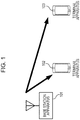
- Fig. 1 is a schematic diagram depicting one example of a downlink (forward link) of a cellular system according to a first embodiment of the present invention.
- one base station apparatus (eNB) 101 is present, and a terminal apparatus 102 and a terminal apparatus 103 to be connected to the base station apparatus 101 are present.
- the base station apparatus 101 multiplexes signals to the terminal apparatus 102 and the terminal apparatus 103 for transmission with the same sub-carrier.
- Fig. 2 is a block diagram depicting one example of the structure of a transmitter of a conventional base station apparatus 101 which performs DL-NOMA.
- the number of signals to be multiplexed is assumed to be 2.
- Information bits are inputted to a coding unit 201-1 and a coding unit 201-2, where error correction coding is applied. Note that which coding rate is to be used in error correction coding is determined based on, for example, information about MCS inputted from a scheduling unit 206. Also, at the coding unit 201-1 and the coding unit 201-2, process capable of improving effects of error correction such as bit interleave may be performed.
- Error-correction coded bits are inputted to a modulation unit 202-1 and a modulation unit 202-2, respectively, where process of transforming a bit sequence to a modulation symbol sequence is performed.
- the generated modulation symbol is of quadrature phase shift keying (QPSK), 16 quadrature amplitude modulation (QAM), 64 QAM, or the like, and different modulation schemes may be used between the modulation unit 202-1 and the modulation unit 202-2.
- QPSK quadrature phase shift keying
- QAM quadrature amplitude modulation
- 64 QAM 64 QAM
- different modulation schemes may be used between the modulation unit 202-1 and the modulation unit 202-2.
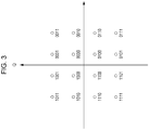
- which modulation scheme is to be used is determined based on information about MCS inputted from the scheduling unit 206, for example. For example, when the modulation scheme applied at the modulation unit 202-1 is 16 QAM, of modulation symbol candidate points depicted in Fig.
- any one of the points is transmitted depending on the transmission bit sequence.
- a numeral accompanying a signal candidate point of Fig. 3 represents a bit sequence for configuring that signal candidate point, and the I axis represents in-phase components, and the Q axis represents orthogonal components.
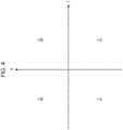
- the modulation scheme applied at the modulation unit 202-2 is QPSK
- modulation symbol candidate points depicted in Fig. 4 any one of the points is transmitted.
- each terminal apparatus is notified of information about MCS in each terminal apparatus via a control information channel.
- Outputs from the modulation unit 202-1 and the modulation unit 202-2 are inputted to a power assignment unit 203-1 and a power assignment unit 203-2, respectively.
- power assignment is performed so that a total value of average powers of the outputs from the modulation unit 202-1 and the modulation unit 202-2 is a predetermined value.
- This power assignment is determined in advance or determined in consideration of cell throughput, user throughput, or the like at the scheduling unit 206, and is performed based on values inputted to the power assignment unit 203-1 and the power assignment unit 203-2.
- Outputs from the power assignment unit 203-1 and the power assignment unit 203-2 are inputted to resource assignment units 204-1 and 204-2, respectively.
- signals inputted from the power assignment unit 203-1 and the power assignment unit 203-2 are each mapped to a predetermined sub-carrier in accordance with assignment information inputted from the scheduling unit 206.
- the scheduling unit 206 determines resource assignment so that the resource assignment units 204-1 and 204-2 each use a different resource. For example, resource assignment is made to each terminal apparatus as depicted in Fig. 5(a) . That is, resources used by the resource assignment units 204-1 and 204-2 do not overlap each other.
- the resource assignment units 204-1 and 204-2 perform the same resource assignment. For example, resources are assigned to each terminal apparatus, as depicted in Fig. 5(b) .
- the resource assignment units 204-1 and 204-2 assign, to each terminal apparatus, not only exactly the same resources or resources not overlapping each other but also resources, for example, as depicted in Fig. 6(a) or Fig. 6(b) . That is, according to the present embodiment, resources can be assigned so that part of the assigned resources overlap. The reason why such resource assignment can be performed will be described further below. Note that as power assignment at the power assignment unit 203-1 and the power assignment unit 203-2, as depicted in Fig. 6(a) and Fig.
- the same power may be assigned in all of a plurality of sub-carriers to be used for signals to the respective terminal apparatuses, or power may be changed for each sub-carrier depending on whether non-orthogonal multiplexing has been performed, the number of times of non-orthogonal multiplexing, or the like.
- Outputs from the resource assignment units 204-1 and 204-2 are inputted to a signal addition unit 205.
- the outputs from the resource assignment units 204-1 and 204-2 are added (combined; superposition coding) for each sub-carrier.
- superposition coding When part or all of the assigned resources at the resource assignment units 204-1 and 204-2 overlap, non-orthogonal multiplexing by superimposing (superposition coding) is performed at that resource (sub-carrier).
- the signal addition unit 205 transmits any one of the points in a signal point constellation as depicted in Fig. 7 .
- labeling in Fig. 7 represents only bit sequences to be transmitted to a terminal apparatus by 16 QAM.
- An output from the signal addition unit 205 is inputted to a control information multiplexing unit 207.
- process of multiplexing control information and so forth for reception process at the terminal apparatus is applied.
- control information MCS, assignment information, and so forth are included.
- An output from the control information multiplexing unit 207 is inputted to an OFDM signal generation unit 208.
- the structure of the OFDM signal generation unit 208 is depicted in Fig. 8 . As depicted in Fig.
- the output from the control information multiplexing unit 207 is inputted to an IFFT unit 801, where transformation from a frequency domain signal to a time domain signal is performed by inverse fast Fourier transform (IFFT).
- An output from the IFFT unit 801 is inputted to a CP attachment unit 802, where a cyclic prefix (CP) is attached in order to acquire tolerance to delay waves.
- An output from the CP attachment unit 802 is inputted to a wireless transmission unit 803, where process such as digital to analog (D/A) conversion, band-limiting filtering, up-conversion, or the like is applied.
- An output from the wireless transmission unit 803 is transmitted as an output from the OFDM signal generation unit 208 from a transmit antenna 209 of Fig. 2 .
- FIG. 9 A conventional example of the structure of a receiver of the terminal apparatus 102 which receives a signal subjected to DL-NOMA is depicted in Fig. 9 .
- a signal received via a receive antenna 900 is inputted to an OFDM received signal processing unit 901.
- One example of the structure of the OFDM received signal processing unit 901 is depicted in Fig. 10 .
- the signal received at the receive antenna 900 is inputted to a wireless reception unit 1001, where process such as down conversion, filtering, A/D conversion, or the like is performed.
- An output from the wireless reception unit 1001 is inputted to a CP removal unit 1002, where the CP inserted on a transmission side is removed.
- An output from the CP removal unit 1002 is inputted to an FFT unit 1003, where transformation from the time domain signal to a frequency domain signal is performed by FFT.
- An output from the FFT unit 1003 is inputted to a control information demultiplexing unit 902 of Fig. 9 .
- the control information is demultiplexed.
- the acquired control information (such as MCS and assignment information) is used for reception process at a later stage.
- a signal other than the control information is inputted to a resource extraction unit 903.
- a resource (sub-carrier) to which a signal to the terminal apparatus 102 is mapped is extracted. Note that information for resource extraction is included in the control information acquired at the control information demultiplexing unit or control information separately notified from a higher layer.
- An output from the resource extraction unit 903 is inputted to a channel compensation unit 904.
- channel estimation is performed with a demodulation reference signal (DMRS), cell-specific reference signal (CRS), or the like transmitted from the base station apparatus together with a data signal to compensate for influences received on a propagation channel (channel) by using the acquired channel estimation value.
- DMRS demodulation reference signal
- CRS cell-specific reference signal
- An output from the channel compensation unit 904 is inputted to a demodulation unit 905 and a cancellation unit 906.
- demodulation is performed by the modulation scheme used at the terminal 101. Note that, as described above, the terminal apparatus 102 has been notified of the MCS of the terminal apparatus 103.
- An output from the demodulation unit 905 is inputted to a decoding unit 907, where decoding is performed based on information about the MCS of the terminal apparatus 103.
- An information bit sequence to the terminal apparatus 103 acquired by decoding is inputted to a coding unit 908 for recoding.
- a coding rate is determined based on the information about the MCS of the terminal apparatus 103. That is, at the coding unit 908, process similar to that of the coding unit 201-1 of Fig. 2 is performed.
- An output from the coding unit 908 is inputted to a modulation unit 909, where modulation is performed based on the information about the MCS of the signal to the terminal apparatus 103.
- a control value at the power assignment unit 910 may be notified from the base station apparatus 101 or may be estimated from a reference signal such as DMRS or CRS.
- An output from the power assignment unit 910 is inputted to the cancellation unit 906.
- the cancellation unit 906 from the signal inputted from the channel compensation unit 904, a signal to the terminal apparatus 103 outputted from the power assignment unit 910 is subtracted (cancelled), thereby acquiring a modulation symbol to the terminal apparatus 102.
- An output from the cancellation unit 906 is inputted to a demodulation unit 911, where demodulation is performed based on the MCS of the terminal apparatus 102.
- the terminal apparatus in which cancellation of a signal to another terminal apparatus is assumed has to be notified, by the base station apparatus, of the MCS for use by the other terminal apparatus for communication.
- the types of MCS have a limitation, it is also possible to consider a try-out of all MCSs of the other terminal apparatus.
- the amount of calculation becomes enormous, and this is not practical.
- the structure of a receiver is used in which maximum likelihood detection (MLD) is used for signal demultiplexing at the receiver and the signal to the other terminal is not decoded.
- MLD maximum likelihood detection
- One example of the structure of a receiver in the present embodiment is depicted in Fig. 11 . Since processes until the output from a resource assignment unit 1104 is acquired are similar to those depicted in Fig. 9 , description of the processes is omitted.
- a maximum likelihood detection unit 1105 first compensates for influences of the channel.
- a reference signal such as CRS or DMRS described above
- CRS or DMRS described above which is a known signal
- channel compensation is performed.
- the maximum likelihood detection unit 1105 performs the subsequent signal processing by assuming that, among candidate points, a candidate point "1011" at the shortest distance to the received signal point has been transmitted.
- the modulation scheme used for the signal to a local station and the modulation scheme used for the signal to another terminal apparatus subjected to non-orthogonal multiplexing are required. That is, to decode the signal to the other signal, the coding rate and the assignment information of the other signal are not required in the structure of the receiver in the present invention.
- the control information may be notified with a frame (sub-frame) where the data transmission is being performed, or may be notified in advance by a higher layer (for example, radio resource control (RRC)).
- RRC radio resource control
- the signal to the other terminal does not have to be decoded. Therefore, decoding of the signal to the local station can be made even without the limitation that the same resource assignment is performed on terminal apparatuses joining non-orthogonal multi-access or notification of the MCS and the assignment information of the signal to the other terminal. That is, without significantly increasing control information, non-orthogonal multiplexing can be performed independently of assignment of the other terminal. As a result, an increase in the number of terminals performing non-orthogonal multi-access can be addressed, each terminal can perform transmission by appropriate resource assignment, and therefore throughput can be increased.
- resource assignment can be flexibly performed by using maximum likelihood detection (MLD).
- MLD maximum likelihood detection
- the signal to the local station can be decoded without decoding of the signal to the other terminal.
- a power difference is large in power assignment to a plurality of terminals performing non-orthogonal multiplexing, as depicted in Fig. 7 , a distance between signal points due to different transmission bits of the signal to the other station is longer compared with a distance between signal points due to different transmission bits to the local station. That is, it is possible to detect a signal to the local station as being relatively less prone to receive influences by non-orthogonal multiplexing.
- Fig. 14 depicts a structure approximately similar to that of Fig. 2 , but is different in that the modulation unit 202-1 and the modulation unit 202-2 are changed to a modulation symbol generation unit 1402-1 and a modulation symbol generation unit 1402-2.
- the process of the modulation symbol generation unit 1402-1 and the modulation symbol generation unit 1402-2 is described.
- the modulation scheme for use at the modulation symbol generation unit 1402-1 is 16 QAM and the modulation scheme for use at the modulation symbol generation unit 1402-2 is QPSK
- signal point candidates outputted from a signal addition unit 1405 are as in Fig. 15 .
- the modulation symbol generation unit 1402-1 changes mapping or labeling at the modulation symbol generation unit 1402-1 by the bit sequence.
- the modulation symbol generation unit 1402-1 conventionally performs fixed mapping irrespectively of the bit sequence inputted to the modulation symbol generation unit 1402-2
- the modulation symbol generation unit 1402-1 of the present embodiment changes mapping by the signal to the other signal.
- the modulation symbol generation unit 1402-1 and the modulation symbol generation unit 1402-2 perform labeling to each signal point so that the signal after non-orthogonal multiplexing is line-symmetric to the I axis and the Q axis with reference to mapping of 16 QAM in the first quadrant.
- an adjacent signal candidate point can also be regarded as the same signal point for the terminal apparatus having 16 QAM transmitted thereto. Therefore, bit error or symbol error can be made less prone to occur.
- the modulation symbol generation unit 1402-1 changes mapping based on a bit sequence configuring a modulation symbol at the modulation symbol generation unit 1402-2.
- the modulation symbol generation unit 1402-1 performs process similar to that of the conventional modulation unit (the modulation unit 202-1 of Fig. 2 ).
- the exclusive OR is 1
- the modulation symbol generation unit 1402-1 generates a modulation symbol as conventional, and then performs process of inverting a code on the I axis.
- the modulation symbol generation unit 1402-1 performs process as conventional (the modulation unit 202-1 of Fig. 2 ).
- the exclusive OR is 1
- the modulation symbol generation unit 1402-1 generates a modulation symbol as conventional, and then performs process of inverting a code on the Q axis.
- the above-described modulation scheme can be applied not only to QAM but also to BPSK. Since binary phase shift keying (BPSK) does not have orthogonal components (values on the Q axis), the above-described method is applied only to in-phase components (values on the I axis).
- BPSK binary phase shift keying
- Fig. 11 one example of the structure of a receiver in the present embodiment is depicted in Fig. 11 .
- the structure of the receiver in the present embodiment is approximately similar to that of the first embodiment, but is different in the process at the maximum likelihood detection unit 1105.
- transmission signal candidate points as in Fig. 15 are generated, and a candidate point at the closest distance from the received signal point is calculated as a transmit signal point. This is an example when a hard decision is made. As with the first embodiment, however, a soft decision may be performed to calculate a bit LLR.
- mapping scheme Gray coding
- an adjacent bit is a signal point different by one bit
- a further adjacent signal point is a signal point different by two bits.
- mapping can be made in a manner such that a signal adjacent to an adjacent signal point is different only by one bit, thereby allowing a bit error rate to be decreased. That is, the bit error rate can be reduced even if relatively large noise occurs.
- maximum likelihood detection is performed as process at the receiver in the present embodiment, not only maximum likelihood but also any can be effective as a detection method. For example, it is also effective when a replica is generated based on a soft decision result in a symbol level interference canceller or an interference canceller of a code word level.
- a program operating on the base station apparatus and the terminal apparatus is a program which controls a CPU and so forth so as to achieve the functions of the above-described embodiments regarding the present invention. And, information handled in these apparatuses is temporarily accumulated in a RAM at the time of processing thereof, then stored in various ROMs and HDDs, and read by the CPU as required for correction and writing.
- a recording medium which stores the program any of semiconductor media (for example, ROM, non-volatile memory card, and so forth), optical recording media (for example, DVD, MO, MD, CD, BD, and so forth), magnetic recording media (for example, magnetic tape, flexible disc, and so forth), and so forth may suffice.
- the functions of the above-described embodiments are achieved not only by executing the loaded program. Based on an instruction of that program, the functions of the present invention may be achieved also by processing in association with an operating system, another application program, or the like.
- the program can be stored in a portable recording medium for distribution, or can be transferred to a server computer connected via a network such as the Internet.
- a storage apparatus of the server computer is also included in the present invention.
- an entire or part of the terminal apparatus and the base station apparatus in the above-described embodiments may be achieved as, typically, an LSI, which is an integrated circuit.
- Function blocks of the reception apparatus may be each made individually into a chip, or an entire or part thereof may be integrated into a chip. When each of the function blocks is made into an integrated circuit, an integrated circuit control unit which controls those is added.
- circuit integration scheme is not restricted to LSI, but circuit integration may be achieved by a dedicated circuit or a general-purpose processor. Also, if a circuit integration technique as an alternative to LSI emerges with the advance of semiconductor technology, an integrated circuit by that technique can be used.
- the invention of the present application is not restricted to the above-described embodiments. It goes without saying that the terminal apparatus of the invention of the present application is not restricted to be applied to a mobile station apparatus and can be applied to stationary-type or non-movable-type electronic devices installed indoors or outdoors, for example, AV devices, kitchen devices, cleaning/washing devices, air conditioners, office devices, automatic vending machines, and other home devices.
- the present invention is suitable for use in a terminal apparatus, base station apparatus, communication system, and communication method.
Landscapes
- Engineering & Computer Science (AREA)
- Signal Processing (AREA)
- Computer Networks & Wireless Communication (AREA)
- Quality & Reliability (AREA)
- Mobile Radio Communication Systems (AREA)
- Transmitters (AREA)
Applications Claiming Priority (2)
| Application Number | Priority Date | Filing Date | Title |
|---|---|---|---|
| JP2015004610 | 2015-01-14 | ||
| PCT/JP2016/051011 WO2016114359A1 (fr) | 2015-01-14 | 2016-01-14 | Dispositif de station de base et dispositif de terminal |
Publications (2)
| Publication Number | Publication Date |
|---|---|
| EP3258626A1 true EP3258626A1 (fr) | 2017-12-20 |
| EP3258626A4 EP3258626A4 (fr) | 2018-10-31 |
Family
ID=56405899
Family Applications (1)
| Application Number | Title | Priority Date | Filing Date |
|---|---|---|---|
| EP16737430.5A Ceased EP3258626A4 (fr) | 2015-01-14 | 2016-01-14 | Dispositif de station de base et dispositif de terminal |
Country Status (5)
| Country | Link |
|---|---|
| US (1) | US10136397B2 (fr) |
| EP (1) | EP3258626A4 (fr) |
| JP (1) | JP6716469B2 (fr) |
| CN (1) | CN107210838B (fr) |
| WO (1) | WO2016114359A1 (fr) |
Families Citing this family (5)
| Publication number | Priority date | Publication date | Assignee | Title |
|---|---|---|---|---|
| CN107926032A (zh) * | 2015-09-11 | 2018-04-17 | 富士通株式会社 | 信息传输装置、方法以及通信系统 |
| CN107707496B (zh) * | 2016-08-09 | 2022-04-29 | 中兴通讯股份有限公司 | 调制符号的处理方法及装置 |
| EP3771123B1 (fr) * | 2016-08-12 | 2022-02-16 | Panasonic Intellectual Property Corporation of America | Dispositif et procédé de réception |
| WO2018030204A1 (fr) * | 2016-08-12 | 2018-02-15 | パナソニック インテレクチュアル プロパティ コーポレーション オブ アメリカ | Dispositif de transmission, dispositif de réception, procédé de transmission, et procédé de réception |
| JP2020017779A (ja) * | 2016-11-02 | 2020-01-30 | 株式会社Nttドコモ | ユーザ装置、及び信号受信方法 |
Family Cites Families (13)
| Publication number | Priority date | Publication date | Assignee | Title |
|---|---|---|---|---|
| US4806881A (en) * | 1987-08-28 | 1989-02-21 | Hewlett-Packard Company | Multi-channel modulated numerical frequency synthesizer |
| JP4540284B2 (ja) * | 1999-11-23 | 2010-09-08 | トムソン ライセンシング | 変化するグループ化係数を有するヒエラキカルqam伝送システム |
| KR100569402B1 (ko) | 2001-02-21 | 2006-04-07 | 마츠시타 덴끼 산교 가부시키가이샤 | 통신 시스템에 있어서의 하이브리드 arq 전송 방법, 전송 장치 및 이를 구비한 기지국 장치, 통신 단말 장치 및 통신 시스템 |
| CN101091345A (zh) * | 2004-12-27 | 2007-12-19 | 松下电器产业株式会社 | 无线发送装置、无线接收装置、无线发送方法及无线接收方法 |
| US7729232B2 (en) * | 2006-02-01 | 2010-06-01 | Lg Electronics Inc. | Method of transmitting and receiving data using superposition modulation in a wireless communication system |
| WO2010029615A1 (fr) * | 2008-09-09 | 2010-03-18 | 富士通株式会社 | Émetteur, procédé de transmission, récepteur et procédé de réception |
| EP2219312A1 (fr) * | 2009-02-11 | 2010-08-18 | NTT DoCoMo, Inc. | Appareil pour fournir un signal numérique combiné |
| JP5869836B2 (ja) | 2011-05-20 | 2016-02-24 | 株式会社Nttドコモ | 受信装置、送信装置及び無線通信方法 |
| JP5785845B2 (ja) | 2011-05-20 | 2015-09-30 | 株式会社Nttドコモ | 受信装置、送信装置及び無線通信方法 |
| JP5871362B2 (ja) * | 2011-08-29 | 2016-03-01 | 学校法人日本大学 | 変復調方法 |
| JP6050028B2 (ja) * | 2012-05-25 | 2016-12-21 | シャープ株式会社 | 端末、基地局、通信方法及び集積回路 |
| JP5775105B2 (ja) * | 2013-03-04 | 2015-09-09 | 日本電信電話株式会社 | 受動光通信網における送信装置/方法及び受信装置/方法 |
| JP6031000B2 (ja) * | 2013-06-07 | 2016-11-24 | 日本電信電話株式会社 | 無線通信方法、送信側装置、受信側装置、及び無線通信システム |
-
2016
- 2016-01-14 WO PCT/JP2016/051011 patent/WO2016114359A1/fr not_active Ceased
- 2016-01-14 EP EP16737430.5A patent/EP3258626A4/fr not_active Ceased
- 2016-01-14 CN CN201680005974.6A patent/CN107210838B/zh active Active
- 2016-01-14 US US15/543,017 patent/US10136397B2/en active Active
- 2016-01-14 JP JP2016569510A patent/JP6716469B2/ja active Active
Also Published As
| Publication number | Publication date |
|---|---|
| JP6716469B2 (ja) | 2020-07-01 |
| CN107210838A (zh) | 2017-09-26 |
| JPWO2016114359A1 (ja) | 2017-11-16 |
| CN107210838B (zh) | 2019-12-06 |
| US20180035390A1 (en) | 2018-02-01 |
| US10136397B2 (en) | 2018-11-20 |
| EP3258626A4 (fr) | 2018-10-31 |
| WO2016114359A1 (fr) | 2016-07-21 |
Similar Documents
| Publication | Publication Date | Title |
|---|---|---|
| US11750423B2 (en) | Common phase error and/or inter-carrier interference | |
| EP3497785B1 (fr) | Procédé pour le multiplexage multi-utilisateurs de signaux d'espace temps-fréquence orthogonaux | |
| CN107534508B (zh) | 终端装置及基站装置 | |
| KR102534065B1 (ko) | 기지국 장치 및 단말 장치 | |
| US10136397B2 (en) | Base station apparatus and terminal apparatus | |
| US20160182193A1 (en) | Base station apparatus, terminal apparatus, and integrated circuit | |
| US20170279561A1 (en) | Base station device and terminal device | |
| EP3355607A1 (fr) | Dispositif de station de base, dispositif de terminal, et procédé de communication | |
| CN103858401B (zh) | 无线通信系统中灵活的消息传送 | |
| CN109981241B (zh) | 一种下行多用户叠加的传输方法和装置 | |
| EP3355604A1 (fr) | Dispositif de station de base, dispositif terminal et procédé de communication | |
| US20160173234A1 (en) | Base station apparatus, terminal device, and transmission method | |
| JP5441811B2 (ja) | 受信装置、基地局装置、無線通信システム、伝搬路推定方法、制御プログラムおよび集積回路 | |
| HK40093164A (en) | Common phase error and/or inter-carrier interference | |
| JP2018056812A (ja) | 基地局装置、端末装置及び通信方法 | |
| JP2018101818A (ja) | 端末装置および基地局装置 | |
| HK1198851B (en) | Flexible transmission of messages in a wireless communication system |
Legal Events
| Date | Code | Title | Description |
|---|---|---|---|
| STAA | Information on the status of an ep patent application or granted ep patent |
Free format text: STATUS: THE INTERNATIONAL PUBLICATION HAS BEEN MADE |
|
| PUAI | Public reference made under article 153(3) epc to a published international application that has entered the european phase |
Free format text: ORIGINAL CODE: 0009012 |
|
| STAA | Information on the status of an ep patent application or granted ep patent |
Free format text: STATUS: REQUEST FOR EXAMINATION WAS MADE |
|
| 17P | Request for examination filed |
Effective date: 20170808 |
|
| AK | Designated contracting states |
Kind code of ref document: A1 Designated state(s): AL AT BE BG CH CY CZ DE DK EE ES FI FR GB GR HR HU IE IS IT LI LT LU LV MC MK MT NL NO PL PT RO RS SE SI SK SM TR |
|
| AX | Request for extension of the european patent |
Extension state: BA ME |
|
| DAV | Request for validation of the european patent (deleted) | ||
| DAX | Request for extension of the european patent (deleted) | ||
| A4 | Supplementary search report drawn up and despatched |
Effective date: 20181001 |
|
| RIC1 | Information provided on ipc code assigned before grant |
Ipc: H04J 11/00 20060101ALI20180925BHEP Ipc: H04B 1/04 20060101ALI20180925BHEP Ipc: H04L 27/36 20060101ALI20180925BHEP Ipc: H04J 99/00 20090101AFI20180925BHEP |
|
| STAA | Information on the status of an ep patent application or granted ep patent |
Free format text: STATUS: EXAMINATION IS IN PROGRESS |
|
| 17Q | First examination report despatched |
Effective date: 20190924 |
|
| APBK | Appeal reference recorded |
Free format text: ORIGINAL CODE: EPIDOSNREFNE |
|
| APBN | Date of receipt of notice of appeal recorded |
Free format text: ORIGINAL CODE: EPIDOSNNOA2E |
|
| APBR | Date of receipt of statement of grounds of appeal recorded |
Free format text: ORIGINAL CODE: EPIDOSNNOA3E |
|
| APAV | Appeal reference deleted |
Free format text: ORIGINAL CODE: EPIDOSDREFNE |
|
| APAF | Appeal reference modified |
Free format text: ORIGINAL CODE: EPIDOSCREFNE |
|
| APBT | Appeal procedure closed |
Free format text: ORIGINAL CODE: EPIDOSNNOA9E |
|
| REG | Reference to a national code |
Ref country code: DE Ref legal event code: R003 |
|
| STAA | Information on the status of an ep patent application or granted ep patent |
Free format text: STATUS: THE APPLICATION HAS BEEN REFUSED |
|
| 18R | Application refused |
Effective date: 20240716 |