EP3258686B1 - Dispositif de détermination de possibilité d'entrée pour véhicule - Google Patents
Dispositif de détermination de possibilité d'entrée pour véhicule Download PDFInfo
- Publication number
- EP3258686B1 EP3258686B1 EP16748946.7A EP16748946A EP3258686B1 EP 3258686 B1 EP3258686 B1 EP 3258686B1 EP 16748946 A EP16748946 A EP 16748946A EP 3258686 B1 EP3258686 B1 EP 3258686B1
- Authority
- EP
- European Patent Office
- Prior art keywords
- vehicle
- dimensional object
- road surface
- areas
- image
- Prior art date
- Legal status (The legal status is an assumption and is not a legal conclusion. Google has not performed a legal analysis and makes no representation as to the accuracy of the status listed.)
- Active
Links
Images


Classifications
-
- H—ELECTRICITY
- H04—ELECTRIC COMMUNICATION TECHNIQUE
- H04N—PICTORIAL COMMUNICATION, e.g. TELEVISION
- H04N7/00—Television systems
- H04N7/18—Closed-circuit television [CCTV] systems, i.e. systems in which the video signal is not broadcast
-
- G—PHYSICS
- G06—COMPUTING OR CALCULATING; COUNTING
- G06V—IMAGE OR VIDEO RECOGNITION OR UNDERSTANDING
- G06V20/00—Scenes; Scene-specific elements
- G06V20/50—Context or environment of the image
- G06V20/56—Context or environment of the image exterior to a vehicle by using sensors mounted on the vehicle
- G06V20/58—Recognition of moving objects or obstacles, e.g. vehicles or pedestrians; Recognition of traffic objects, e.g. traffic signs, traffic lights or roads
-
- B—PERFORMING OPERATIONS; TRANSPORTING
- B60—VEHICLES IN GENERAL
- B60R—VEHICLES, VEHICLE FITTINGS, OR VEHICLE PARTS, NOT OTHERWISE PROVIDED FOR
- B60R21/00—Arrangements or fittings on vehicles for protecting or preventing injuries to occupants or pedestrians in case of accidents or other traffic risks
-
- G—PHYSICS
- G06—COMPUTING OR CALCULATING; COUNTING
- G06T—IMAGE DATA PROCESSING OR GENERATION, IN GENERAL
- G06T1/00—General purpose image data processing
-
- G—PHYSICS
- G06—COMPUTING OR CALCULATING; COUNTING
- G06T—IMAGE DATA PROCESSING OR GENERATION, IN GENERAL
- G06T7/00—Image analysis
- G06T7/10—Segmentation; Edge detection
- G06T7/13—Edge detection
-
- G—PHYSICS
- G06—COMPUTING OR CALCULATING; COUNTING
- G06T—IMAGE DATA PROCESSING OR GENERATION, IN GENERAL
- G06T7/00—Image analysis
- G06T7/10—Segmentation; Edge detection
- G06T7/174—Segmentation; Edge detection involving the use of two or more images
-
- G—PHYSICS
- G06—COMPUTING OR CALCULATING; COUNTING
- G06T—IMAGE DATA PROCESSING OR GENERATION, IN GENERAL
- G06T7/00—Image analysis
- G06T7/60—Analysis of geometric attributes
-
- G—PHYSICS
- G06—COMPUTING OR CALCULATING; COUNTING
- G06V—IMAGE OR VIDEO RECOGNITION OR UNDERSTANDING
- G06V20/00—Scenes; Scene-specific elements
- G06V20/50—Context or environment of the image
- G06V20/56—Context or environment of the image exterior to a vehicle by using sensors mounted on the vehicle
- G06V20/58—Recognition of moving objects or obstacles, e.g. vehicles or pedestrians; Recognition of traffic objects, e.g. traffic signs, traffic lights or roads
- G06V20/586—Recognition of moving objects or obstacles, e.g. vehicles or pedestrians; Recognition of traffic objects, e.g. traffic signs, traffic lights or roads of parking space
-
- G—PHYSICS
- G08—SIGNALLING
- G08G—TRAFFIC CONTROL SYSTEMS
- G08G1/00—Traffic control systems for road vehicles
- G08G1/16—Anti-collision systems
-
- B—PERFORMING OPERATIONS; TRANSPORTING
- B60—VEHICLES IN GENERAL
- B60R—VEHICLES, VEHICLE FITTINGS, OR VEHICLE PARTS, NOT OTHERWISE PROVIDED FOR
- B60R2300/00—Details of viewing arrangements using cameras and displays, specially adapted for use in a vehicle
- B60R2300/30—Details of viewing arrangements using cameras and displays, specially adapted for use in a vehicle characterised by the type of image processing
- B60R2300/304—Details of viewing arrangements using cameras and displays, specially adapted for use in a vehicle characterised by the type of image processing using merged images, e.g. merging camera image with stored images
-
- B—PERFORMING OPERATIONS; TRANSPORTING
- B60—VEHICLES IN GENERAL
- B60R—VEHICLES, VEHICLE FITTINGS, OR VEHICLE PARTS, NOT OTHERWISE PROVIDED FOR
- B60R2300/00—Details of viewing arrangements using cameras and displays, specially adapted for use in a vehicle
- B60R2300/80—Details of viewing arrangements using cameras and displays, specially adapted for use in a vehicle characterised by the intended use of the viewing arrangement
-
- G—PHYSICS
- G06—COMPUTING OR CALCULATING; COUNTING
- G06T—IMAGE DATA PROCESSING OR GENERATION, IN GENERAL
- G06T2207/00—Indexing scheme for image analysis or image enhancement
- G06T2207/20—Special algorithmic details
- G06T2207/20212—Image combination
- G06T2207/20224—Image subtraction
-
- G—PHYSICS
- G06—COMPUTING OR CALCULATING; COUNTING
- G06T—IMAGE DATA PROCESSING OR GENERATION, IN GENERAL
- G06T2207/00—Indexing scheme for image analysis or image enhancement
- G06T2207/30—Subject of image; Context of image processing
- G06T2207/30248—Vehicle exterior or interior
- G06T2207/30252—Vehicle exterior; Vicinity of vehicle
-
- G—PHYSICS
- G06—COMPUTING OR CALCULATING; COUNTING
- G06V—IMAGE OR VIDEO RECOGNITION OR UNDERSTANDING
- G06V2201/00—Indexing scheme relating to image or video recognition or understanding
- G06V2201/12—Acquisition of 3D measurements of objects
Definitions
- This invention relates to a device for processing images around a vehicle that are captured by a camera attached to the vehicle, and particularly to processing by converting the images around the vehicle into an overhead image.
- Patent Literature 1 discloses a method for determining whether a vehicle can pass through an object using a 3D camera. From the image data it is determined whether an object is located above the trajectory of the vehicle and whether the object has connections to the ground. By comparing dimensions and shapes of the object and the vehicle it is determined whether the vehicle can pass.
- Patent Literature 3 refers to a detector which detects the height of an obstacle in front of a vehicle, the detected height being compared with the height of the vehicle.
- Patent Literature 4 discloses a method for detecting objects using projected images and edge detection.
- a vehicle periphery image display device disclosed in Patent Literature 1 can correct the distortion of the three-dimensional objects which are placed on a road surface.
- the portion is projected to be deformed and inclined toward the road surface in a direction away from the vehicle. Therefore, relying on the overhead images, the vehicle may hit the three-dimensional objects when the vehicle is moved close to the three-dimensional objects.
- the three-dimensional object is an object such as a garage the vehicle enters, it cannot be determined whether the vehicle can enter the garage or not only by seeing the overhead images.
- the present invention is made in view of above problems.
- the present invention determines whether there is a space to which a vehicle can access in a three-dimensional object detected on a road surface around the vehicle, and determines whether the vehicle can access to the space or not.
- the vehicle accessibility determination device of the present invention can determine whether the vehicle may hit the three-dimensional objects around the vehicle or not.
- the three-dimensional object has a floating area which does not contact the road surface.
- the three-dimensional object may be a three-dimensional object having a portion floating in the air, or a three-dimensional object having an overhang portion. Accordingly, a driver can be provided with information regarding accessibility of the vehicle to the three-dimensional objects and positions to which the vehicle can access. Therefore, the contact of the vehicle to the three-dimensional objects can be prevented.
- the present invention is adopted to a vehicle accessibility determination device that detects a three-dimensional object around a vehicle, determines whether the vehicle can access to the detected three-dimensional object, and then informs a driver of a result.
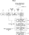
- a vehicle accessibility determination device 100 of the present invention includes an imager 12, an image inputting portion 20, an image convertor 30, a three-dimensional object detector 40, a vehicle accessibility determiner 50, and a vehicle accessible and inaccessible range display 60.
- the imager 12 is mounted to a vehicle 10 to capture images including a road surface in front of the vehicle 10.
- the image inputting portion 20 converts an image signal output from the imager 12 into an original image 70 which is in a digital image format capable of being processed by a computer.
- the image convertor 30 converts the original image 70 into a virtual image 72 viewed from a predetermined viewpoint.
- the three-dimensional object detector 40 detects from the virtual image 72 a three-dimensional object having a height from the road surface.
- the vehicle accessibility determiner 50 determines whether the vehicle 10 can access to the inside of the detected three-dimensional object or to a space defined between the detected three-dimensional objects.
- the vehicle accessible and inaccessible range display 60 displays a range to which the vehicle can access or a range to which the vehicle cannot access as a result of the vehicle accessibility determination by the vehicle accessibility determiner 50.
- the imager 12 is attached to the front portion of the vehicle 10 and captures the inside of a front observation range 14 in the visual field range of 180 degrees.
- the front observation range 14 includes a road surface right before the vehicle 10.
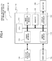
- the three-dimensional object detector 40 specifically includes a first frame difference calculator 40a, a second frame difference calculator 40b, an edge detector 40c, and a three-dimensional object area clustering portion 40d.
- the first frame difference calculator 40a performs a frame difference between two virtual images 72(t), 72(t- ⁇ t) that are generated from two original images 70(t), 70(t- ⁇ t), respectively.
- the two original images 70(t), 70(t- ⁇ t) are captured by the imager 12 ( Fig. 1 ) at a predetermined time interval, converted by the image convertor 30 ( Fig. 1 ), and obtained at different times.
- the second frame difference calculator 40b generates an expected virtual image 72'(t) at time t from the virtual image 72(t- ⁇ t) generated from the original image 70(t- ⁇ t) obtained at time (t- ⁇ t).
- the second frame difference calculator 40b then performs a frame difference for subtracting the expected virtual image 72'(t) from the virtual image 72(t) actually obtained at time t.
- the edge detector 40c detects from the virtual image 72(t) pixels which change in brightness more than adjacent pixels. In other words, the edge detector 40c detects pixels constituting an edge.
- the three-dimensional object area clustering portion 40d detects an area which is considered constituting a three-dimensional object based on the calculated result of the first frame difference calculator 40a and the calculated result of the second frame difference calculator 40b, and the detected result of the edge detector 40c.
- the vehicle accessibility determiner 50 specifically includes a three-dimensional object area extracting portion 50a, a road surface projecting position calculating portion 50b, and a vehicle accessible space identifying portion 50c.
- the three-dimensional object area extracting portion 50a extracts an area corresponding to the three-dimensional object detected by the three-dimensional object detector 40 from the original image 70.
- the road surface projecting position calculating portion 50b calculates a road surface projection position.
- the road surface projection position indicates a limit position in which the vehicle can access to the three-dimensional object relative to the three-dimensional object area extracted by the three-dimensional object area extracting portion 50a.
- the vehicle accessible space identifying portion 50c identifies whether there is a space inside the three-dimensional object or in a clearance among other three-dimensional objects to which the vehicle 10 can access.
- the vehicle accessibility determination device 100 includes ECU (electronic control unit) 110, a front camera 12a, a vehicle condition sensor 140, and a monitor 150.
- ECU 110 is mounted to the vehicle 10 and performs required image processing and/or arithmetic processing.
- the front camera 12a is connected to ECU 110 and constitutes the imager 12 ( Fig. 1 ).
- the vehicle condition sensor 140 calculates a moving direction and a moving amount of the vehicle 10 by sensing the behavior of the vehicle 10.
- the vehicle condition sensor 140 consists of a steering angle sensor and/or a distance sensor.
- the monitor 150 displays a processed result of the vehicle accessible and inaccessible range display 60 ( Fig. 1 ).
- ECU 110 includes CPU 112, a camera interface 114, a sensor interface 116, an image processing module 118, a memory 120, and a display controller 122.
- CPU 112 receives and transmits required data, and executes programs.
- the camera interface 114 is connected to CPU 112 and controls the front camera 12a.
- the sensor interface 116 obtains measured results of the vehicle condition sensor 140.
- the image processing module 118 performs image processing with predetermined programs stored in the module 118.
- the memory 120 stores intermediate results of the image processing, required constants, programs, or the like.
- the display controller 122 controls the monitor 150.
- the image inputting portion 20, the image convertor 30, the three-dimensional object detector 40, the vehicle accessibility determiner 50, and the vehicle accessible and inaccessible range display 60 described in Fig. 1 are respectively controlled with pieces of software, each of which achieves an operation described below.
- the pieces of software are stored in the memory 120 and executed when needed. Note that the pieces of software may be stored in CPU 112 and/or the image processing module 118 if required.
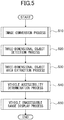
- Step S10 An image conversion process is performed. Specifically, the captured original image is converted into the virtual image.
- Step S20 A three-dimensional object detection process is performed. The detailed process will be described later.
- Step S30 A three-dimensional object area extraction process is performed. The detailed process will be described later.
- Step S40 A vehicle accessibility determination process is performed. The detailed process will be described later.
- Step S50 A vehicle inaccessible range display process is performed. The detailed process will be described later.
- the image inputting portion 20 converts an output from the front camera 12a ( Fig. 4 ), which constitutes the imager 12, into a digital image.
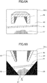
- the converted digital image is input to the image convertor 30 as the original image 70 shown in Fig. 6A . Note that the original image captured at time t is indicated with 70(t).
- the original image 70(t) in Fig. 6A is a captured image of a road surface 80 in front of the vehicle 10 ( Fig. 1 ).
- a lane marker 81 is drawn on the road surface, and a garage 82 (a three-dimensional object) for parking the vehicle 10 is located behind the lane marker 81.
- the garage 82 has leg portions 83, 85 on the left and the right sides of the garage 82, respectively.
- a vehicle shadow 87 which is the shadow of the vehicle 10 is shown in the bottom of the original image 70(t).
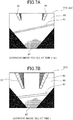
- the image convertor 30 converts the original image 70(t) shown in Fig. 6A into the virtual image 72(t) (overhead image or bird's-eye view image) viewed from directly above the vehicle 10 as shown in Fig. 6B .
- the virtual image 72(t) is obtained by performing the coordinate conversion on the original image 70(t) using installation layout information (a height of the camera, a depression angle of the camera, lens parameters) of the front camera 12a ( Fig. 4 ).
- the coordinate conversion is to be projected to the road surface on which the vehicle 10 is located. Note that the virtual image converted from the original image 70(t) is indicated with 72(t).
- the left and right leg portions 83, 85 are projected as deformed on the virtual image 72(t). Specifically, the left and right leg portions 83, 85 are projected to be inclined toward the road surface in a direction away from the vehicle 10 as the leg portions 83, 85 go upward. In other words, the leg portions 83, 85 are projected to be deformed such that a width between the leg portions 83, 85 becomes wider in the top of the virtual image 72(t).
- leg portions 83, 85 that is, the deformation in areas each having a height from the road surface occurs to spread radially toward the periphery of the virtual image 72(t) from a installation position PI ( Fig. 6B ) of the front camera 12a ( Fig. 4 ).
- invisible areas 86, 86 which are outside the field of view of the front camera 12a, are generated in the virtual image 72(t). Accordingly, predetermined gray values (0, for example) are stored in the invisible areas 86, 86.
- the three-dimensional object detector 40 detects three-dimensional objects from the virtual images respectively generated from two original images that are captured at a time interval ⁇ t.
- the description is made as the three-dimensional objects are to be detected from the virtual image 72(t) generated from the original image 70(t) captured at time t, and the virtual image 72(t- ⁇ t) generated from the original image 70(t- ⁇ t) captured at time t- ⁇ t.
- a frame difference of the two virtual images 72(t), 72(t- ⁇ t) is calculated. This process is performed in the first frame difference calculator 40a shown in Fig. 3 .
- the virtual image 72(t) at time t is expected from the virtual image 72(t- ⁇ t) to generate an expected virtual image 72'(t).
- a frame difference of the expected virtual image 72'(t) and the virtual images 72(t) actually obtained at time t is calculated. This process is performed in the second frame difference calculator 40b shown in Fig. 3 .
- the expected virtual image 72'(t) is generated as follows.
- the vehicle condition sensor 140 ( Fig. 4 ) measures the traveling amount and the moving direction of the vehicle 10 for the time interval ⁇ t whenever necessary.
- the virtual image 72(t- ⁇ t) is translated and rotated to correspond to the measured traveling amount and moving direction for the time interval ⁇ t, and accordingly, the expected virtual image 72'(t) at time t is generated.
- the expected virtual image 72'(t) is generated on the assumption that the whole road surface is reflected on the virtual image 72(t- ⁇ t).
- the frame difference in the second frame difference calculator 40b may be performed between the expected virtual image 72'(t- ⁇ t) and the virtual image 72(t- ⁇ t) actually obtained at time t- ⁇ t, after generating the expected virtual image 72'(t- ⁇ t) at time t- ⁇ t based on the virtual image 72(t) at time t.
- Performing the frame deference between the virtual image 72(t) and the expected virtual image 72'(t) matches positions of patterns drawn on the road surface such as the lane marker 81 shown in Fig. 7B . Accordingly, the lane marker 81 can be restrained or deleted as shown in Fig. 7D .
- the vehicle shadow 87 on the road surface is formed in the substantially same positions even when the vehicle 10 moves during a short time interval for which the frame difference is performed. As a result, the vehicle shadow 87 cannot be deleted with the frame difference between the virtual image and the expected virtual image as shown in Fig. 7D .
- the vehicle shadow 87 formed in the substantially same positions can be deleted as shown in Fig. 7C with the frame difference of the two virtual image 72(t), 72(t- ⁇ t) actually obtained at two different times. Patterns drawn on the road surface such as the lane marker 81 cannot be deleted with this frame difference since an observation position moves as the vehicle moves.
- a result of the frame difference performed in the first frame difference calculator 40a ( Fig. 7C ) is compared with a result of the frame difference performed in the second frame difference calculator 40b ( Fig. 7D ).
- the areas detected with the frame difference in the second frame difference calculator 40b can be presumed as the vehicle shadow 87 on the road surface or reflections that occur on the road surface by the sun or the lighting lamp. Then, the areas are deleted since the areas are determined not to represent three-dimensional objects.
- the fact that the areas obtained as a result of the frame differences are inclined toward the road surface in the direction away from the vehicle 10 can be determined by referring to a result of an edge detection from the vertical image 72(t) and by confirming that edge directions in the areas obtained as a result of the frame differences extend along radial lines through the installation position PI ( Fig. 6B ) of the front camera 12a ( Fig. 4 ).
- a result of the first frame difference shown in Fig. 7C is binarized with a predetermined threshold value, and pixels having gray values larger than the threshold value are detected as first three-dimensional object candidate areas (not shown). This process detects areas such as the leg portions 83, 85 and/or the lane marker 81.
- a result of the second frame difference shown in Fig. 7D is binarized with a predetermined threshold value, and pixels having gray values larger than the threshold value are detected as second three-dimensional object candidate areas (not shown). This process detects areas such as the leg portions 83, 85 and/or the vehicle shadow 87.
- deletion of non three-dimensional objects is performed. This process can delete non three-dimensional objects whose positions are moved as the vehicle moves. Specifically, the areas of the lane marker 81 and/or the vehicle shadow 87 can be deleted. The deletion of the non three-dimensional objects can be carried out, for example by performing a logical AND operation on the detected first and second three-dimensional object candidate areas.
- features used in this embodiment are not limited to shapes of the areas. Specifically, areas located in close positions relative to each other may be detected using the luminance differences of the areas. Further, as features, similarity (similarity in edge directions, edge intensity) obtained as a result of performing the edge detection on the virtual images may be used. Also, similarity of a histogram of the edge detection result or a density histogram obtained from each of a plurality of small blocks made by dividing the virtual images, or the like may be used.
- the edge detector 40c ( Fig. 3 ) performs an edge detection on the vertical image 72(t).
- the edge detection is performed by calculating difference in brightness between adjacent pixels as generally performed.
- a direction in which each of the areas extends is evaluated by referring to a result of the edge detection of the pixels in the same positions as the remaining areas.
- the areas constituting the three-dimensional objects are converted to areas radially extending from the installation position PI ( Fig. 6B ) of the front camera 12a ( Fig. 4 ) toward the periphery of the virtual image 72(t). Accordingly, the areas constituting the three-dimensional objects are determined by confirming the shapes of the areas and/or the extending directions to meet the above condition.
- the areas detected with the frame differences are not directly determined as the three-dimensional areas, but the edge detection result of the virtual image 72(t) is referred. Accordingly, the influence of the time variation of the exposure characteristic of the camera, shadows, lighting, which may be mixed in the results of the frame differences, can be reduced.
- the edge detection result of the virtual image 72(t) is referred, the three-dimensional object area at time t- ⁇ t may not be left as afterimages, and an erroneous detection is suppressed in the case where the three-dimensional objects move. Accordingly, the detection performance of the three-dimensional objects can be further improved.
- the three-dimensional object areas 90, 92 which are considered to constitute three-dimensional objects, are detected with a series of the processes. Then, the lowermost edge positions of the detected three-dimensional object areas 90, 92 are detected as road surface grounding positions 90a, 92a.
- the road surface grounding positions 90a, 92a represent positions where the three-dimensional objects are in contact with the road surface.
- Step S100 The frame difference is performed in the first frame difference calculator 40a.
- Step S110 The frame difference is performed in the second frame difference calculator 40b.
- Step S120 A result of Step S100 is compared with a result of Step S110, and areas moving with the movement of the vehicle 10 are deleted as the non three-dimensional objects.
- Step S130 The edge detection is performed on the virtual image 72(t).
- Step S140 In the remaining areas as a result of Step S120, only areas inclined toward the road surface in the direction away from the vehicle 10 are detected.
- Step S150 Road surface grounding positions of the detected areas are detected.
- a reverse overhead view conversion is performed on the three-dimensional object areas detected from the virtual image 72 to convert the areas into the coordinate system of the original image 70.
- the reverse overhead view conversion identifies the three-dimensional object areas in the original image 70(t) as shown in Fig. 9A .
- upper portions of the garage 82 three-dimensional object
- the superimposition in this embodiment means to superimpose another layer on the original image 70.
- a rectangular area W1 is set in the original image 70(t).
- the outer edge of the rectangular area W1 contacts the outer edges of the three-dimensional object areas 90, 92 in a lateral direction.
- the vertical size of the rectangular area W1 is set to a preset predetermined value.
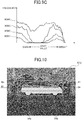
- the three-dimensional object area extracting portion 50a creates a density histogram H (W1) in the area of the original image 70(t) corresponding to the rectangular area W1.
- An example of the density histogram H (W1) created as above is shown in Fig. 9C .
- the density histogram H (W1) includes two areas, namely a dark area and a bright area.
- the dark area forms three-dimensional object areas 90, 92 and the bright area forms non-three-dimensional object areas.
- rectangular areas W2, W3, and W4 are set by increasing the vertical size of the rectangular area W1 by a predetermined value, and the density histograms H (W2), H (W3), and H (W4) of the original image 70(t) corresponding to each of the rectangular areas are created each time the rectangular area is set. Examples of the density histograms H (W2), H (W3), and H (W4) created as above are shown in Fig. 9C .
- the density histograms have similar forms. Specifically, in the example of Fig. 9C , from the density histograms H (W1), H (W2), and H (W3) obtained when the rectangular areas W1, W2, and W3 are set, it can be noticed that two areas, that is the dark area forming the three-dimensional object areas 90, 92 and the bright area forming the non-three-dimensional object areas appear. Then, with regard to the density histogram H (W4) obtained when the rectangular area W4 completely overlaps the three-dimensional object areas 90, 92, the similarity of the density distribution to the others is disrupted.
- the similarities in the density histograms H (Wi) may be evaluated based on a mode method assuming bimodality of the histograms, stability of binarization threshold by discriminant analysis, or the like, by considering variations in the area (dimension) of the three-dimensional object areas and the non-three-dimensional object areas in the rectangular areas Wi.
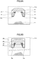
- Fig. 10 is an original image 70(t) captured at time t and showing a condition in which another vehicle 11 (three-dimensional object) is parked in front of the vehicle 10.
- Fig. 10 also shows a condition in which a three-dimensional object area 94 detected by the three-dimensional object area detection is superimposed to the original image 70(t). Locations on which tires of vehicle 11 (three-dimensional object) are grounded are detected as road surface grounding positions 94a, 94b.
- Step S200 The three-dimensional object areas detected from the virtual image 72 are inversely converted and superimposed on the corresponding positions in the original image 70.
- the rectangular areas Wi contact in a lateral direction the three-dimensional object areas superimposed on the original image 70.
- Step S220 The density histograms H (Wi) are created with regard to areas corresponding to the rectangular areas Wi from the original image 70.
- Step S230 Similarities of the created density histograms H (Wi) are calculated to find a set of the density histograms H (Wi) having a high degree of similarity. Then, in the set of the density histograms H (Wi) determined to have the high degree of similarity, a rectangular area Wi having the maximum vertical size is set as the three-dimensional object area.
- Step S240 It is determined whether the three-dimensional object area is set or not. The process of FIG. 11 ends when the three-dimensional object area is set. Otherwise, the process returns to Step S210 to repeat the process for another three-dimensional object candidate area.
- Fig. 11 shows an example of a three-dimensional object area extraction process.
- the three-dimensional object areas may be extracted using another characteristic such as the edge detection result of the virtual image, or the like, in addition to using similarities of the density histograms H (Wi) of the areas as described above.
- Three-dimensional objects on the road surface do not necessarily contact the road surface at their bottom portions thereof. Specifically, there are three-dimensional objects each having a floating area which does not contact the road surface. For example, with regard to the garage 82 (three-dimensional object) shown in Figs. 6A, 6B , only the leg portions 83, 85 contact the road surface, but an area between the leg portions 83, 85 are floating above the road surface. With regard to the other vehicle 11 (three-dimensional object) shown in Fig. 10 , only tires contact the road surface but the other portion (the body of the vehicle) are floating above the road surface.
- a road surface projecting position in which the other vehicle 11 is projected to the road surface from directly above, is calculated.
- the other vehicle 11 is a three-dimensional object area extracted in the three-dimensional object area extraction process. This process is performed in the road surface projecting position calculating portion 50b. The process can detect whether the extracted three-dimensional object area includes portions floating above the road surface.
- a line segment L is set.
- the line segment L extends between the left end and the right end of the other vehicle 11, which is the detected three-dimensional object area.
- the other vehicle 11 also includes the road surface grounding positions 94a, 94b. Then, the positions of points, which are above the line segment L and contacting the other vehicle 11 on the original image 70(t), are detected.
- a point Pi when a search is performed from a point Pi, a point Qi which floats in a space is detected.
- a point Qj which floats in the space is detected.
- the road surface grounding positions 94a, 94b are excluded from the object of the process since the road surface grounding positions 94a, 94b are in contact with the road surface.
- the detected points Qi, Qj, ... which float in the space are projected inversely on the line segment L to set road surface grounding points Ri, Rj, ....
- the road surface grounding positions 94a, 94b remain as road surface grounding points.
- the road surface grounding points Ri, Rj, ... set as described above represent the road surface projecting positions in which the other vehicle 11 (three-dimensional object) is projected to the road surface from directly above.
- the road surface grounding points Ri, Rj obtained as described above the road surface grounding points detected continuously in left and right directions are connected to each other to create road surface grounding lines L1, L2, L3.
- the road surface grounding lines L1, L2, L3 are equal to one line segment.
- the road surface grounding lines L1, L2 are connected to the road surface grounding position 94a, and the road surface grounding lines L2, L3 are connected to the road surface grounding position 94b. Therefore, the road surface grounding positions 94a, 94b and the road surface grounding lines L1, L2, L3 are unified as one road surface grounding line N.
- determination whether the vehicle 10 can farther move beyond the road surface grounding lines Li, Lj, Lk or not is performed by confirming that the length of each of the road surface grounding lines Li, Lj, Lk is longer than the width of the vehicle 10, and there are spaces higher than the height of the vehicle 10 above the road surface grounding lines Li, Lj, Lk.
- the original image 70(t) is generated by receiving a perspective conversion. That is, the farther the portions are located, the shorter the portions are reflected or shown in the upper part of the image. Therefore, actual lengths of the road surface grounding lines Li, Lj, Lk can be estimated with the vertical positions and the lengths of the road surface grounding lines Li, Lj, Lk on the original image 70(t), which are detected in the original image 70(t). Further, the heights of spaces to which the vehicle 10 is accessible in the positions of the road surface grounding lines Li, Lj, Lk can be estimated with the vertical positions of the road surface grounding lines Li, Lj, Lk on the original image 70(t).
- the heights Hi, Hj, Hk of the spaces above each of the road surface grounding lines Li, Lj, Lk necessary for the vehicle 10 to access beyond each of the road surface grounding lines Li, Lj, Lk can be estimated based on the vertical positions of the road surface grounding lines Li, Lj, Lk.
- Actual lengths of the road surface grounding lines Li, Lj, Lk and the heights Hi, Hj, Hk of the spaces above the road surface grounding lines Li, Lj, Lk can be respectively estimated based on installation layout information (the height of the camera, the depression angle of the camera, lens parameters) of the front camera 12a ( Fig. 4 ). Specifically, since the installation layout of the front camera 12a is known in advance, the actual lengths of the respective road surface grounding lines L1, L2, L3, and the heights H1, H2, H3 of the spaces above the road surface grounding lines Li, Lj, Lk can be obtained in advance by calculation. Then, calculated values are stored in the form of a table in the vehicle accessible space identifying portion 50c ( Fig. 1 ).
- each of the road surface grounding lines Li, Lj, Lk exceeds the width of the vehicle 10, and whether there are spaces exceeding the height of the vehicle 10 above the grounding lines Li, Lj, Lk by referring to the contents of the stored table.
- Step S300 The road surface projecting positions of the three-dimensional object areas are calculated as the road surface grounding points Ri, Rj...
- the specific content of the process is as described above.
- Step S310 Among the road surface grounding points Ri, Rj..., successively located points are unified as the road surface grounding line N. Then, the length of the road surface grounding line N, and the vertical position of the road surface grounding line N on the original image 70 are calculated.
- Step S320 The height H of the space above the road surface grounding line N is calculated.
- Step S330 It is determined whether the vehicle 10 can access beyond the road surface grounding line N or not.
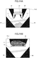
- Fig. 14A shows an example of a display image 74(t) generated from Figs. 6A, 6B .
- the display image 74(t) is displayed in the monitor 150 ( Fig. 4 ) of the vehicle 10.
- the road surface grounding lines L1, L2 are drawn with bold lines on in the virtual image 72(t) (overhead view).
- the three-dimensional object area corresponding to the extracted garage 82 is superimposed and displayed. Since the vehicle 10 can access to an area between the road surface grounding lines L1, L2, a bold line is not drawn in the position of a road surface grounding line.
- a driver of the vehicle 10 decides that the vehicle 10 can be farther moved to the rear side of the garage 82 (three-dimensional object) by seeing the display image 74(t).
- predetermined colors such as red may be added to the bold lines which indicate the road surface grounding lines L1, L2 to improve visibility.
- predetermined gray values (0, for example) are stored in the invisible areas 86 which are outside the field of view of the front camera 12a, and the invisible areas 88 which are the shadow of the garage 82 (three-dimensional object).
- Fig. 14B shows an example of a display image 75(t) generated when the original image 70(t) shown in Fig. 10 is observed.
- display image 75(t) a bold line which indicates the road surface grounding line N is drawn below the other vehicle 11. It shows that the vehicle 10 can approach only to the position of the road surface grounding line N. In other words, it shows that the vehicle 10 cannot access beyond the road surface grounding line N.
- the display form of the display image 74 (t) is not limited to the examples shown in Figs. 14A, 14B . That is, in the road surface grounding line N, bold lines may be displayed relative to a range to which the vehicle 10 can access, not to a range to which the vehicle 10 cannot access.
- the image convertor 30 converts the original image 70 including the road surface around the vehicle 10 which is captured by the front camera 12a (imager 12) into the virtual image 72 (overhead image) viewed from a predetermined viewpoint.
- the three-dimensional object detector 40 detects from the virtual image 72 the three-dimensional object having a height from the road surface.
- the vehicle accessibility determiner 50 determines whether the vehicle 10 can access to the inside of the detected three-dimensional object or to a clearance among other three-dimensional objects. Accordingly, even if the three-dimensional object has a floating area which does not contact the road surface, it can be detected whether the vehicle 10 can access to the space or not. Therefore, it is possible to prevent the vehicle 10 from hitting the three-dimensional object in advance.
- the three-dimensional object area extracting portion 50a extracts an area corresponding to the three-dimensional object from the original image 70.
- the road surface projecting position calculating portion 50b calculates the presence or absence of a floating area that does not contact the road surface and the height of the floating area from the road surface relative to the three-dimensional object area extracted by the three-dimensional object area extracting portion 50a.
- the floating area constitutes the three-dimensional object.
- the road surface projecting position calculating portion 50b calculates the road surface projecting position in which the floating area is projected to the road surface from directly above.
- the vehicle accessible space identifying portion 50c identifies whether there is the space inside the detected three-dimensional object or in the clearance among other three-dimensional objects to which the vehicle 10 can access, based on the presence or absence of the floating area and the road surface projecting position calculated by the road surface projecting position calculating portion 50b. Accordingly, the presence or absence of the floating area and the road surface projecting position can be calculated with a simple process.
- the vehicle accessible and inaccessible range display 60 superimposes, to the road surface position of the virtual image 72, the vehicle inaccessible range to which the vehicle 10 cannot access determined in the vehicle accessibility determiner 50, or the vehicle accessible range to which the vehicle 10 can access determined in the vehicle accessibility determiner 50, and displays the superimposed ranges. Accordingly, it is possible to visualize how far the vehicle 10 can access to the three-dimensional object even if the three-dimensional object has the floating area that does not contact the road surface. Therefore, it is possible to prevent the vehicle 10 from hitting the three-dimensional object in advance.
- the three-dimensional object detector 40 deletes the non three-dimensional objects.
- the deletion of the non three-dimensional objects is made based on a result of the frame difference between the two virtual images 72(t- ⁇ t), 72(t) (overhead images) calculated in the first frame difference calculator 40a, and a result of the frame difference between the expected virtual image 72'(t) and the other virtual image 72(t) calculated in the second frame difference calculator 40b.
- the two virtual images 72(t- ⁇ t), 72(t) (overhead images) are respectively generated from the two original images captured at different times.
- the expected virtual image 72'(t) is expected to be generated from the original image captured at the same time as the time at which the original image (t) is captured which is the conversion source of the other virtual image 72(t), and is expected based on the traveling amount and the moving direction of the vehicle 10 from the virtual image 72(t- ⁇ t) which is one of the two virtual images (overhead images).
- the three-dimensional object detector 40 detects the three-dimensional object on the road surface by referring to the edge information of the virtual image 72(t) detected in the edge detector 40c. Accordingly, it is possible to identify the three-dimensional object having a height from the road surface from paints, stains or darts on the road, or the vehicle shadow 87, and detect the three-dimensional object with a simple process.
- the vehicle accessibility determination device 100 according to the first embodiment of the present invention as configured above, areas having same shapes (features) and located in close positions are detected from the first three-dimensional object candidate areas detected by the first frame difference calculator 40a and the second three-dimensional object candidate areas detected by the second frame difference calculator 40b.
- the detected areas are detected to be inclined toward the road surface in a direction away from the vehicle 10 based on the edge detection result of the virtual image 72(t) by the edge detector 40c, the areas are detected as areas indicating the three-dimensional objects on the road surface. Accordingly, it is possible to reduce the influence of the time variation of the exposure characteristics of the camera, shadows, lighting, which may be mixed in the results of the frame differences, by referring to the edge detection result of the virtual image 72(t). Therefore, the detection performance of the three-dimensional object can be further improved.
- the number of cameras to be used is not limited to one. That is, it is also possible for the vehicle accessibility determination device to include a plurality of cameras directed to the front, the left, the right, and the rear of the vehicle 10 so as to be able to monitor the entire circumference of the vehicle 10.
- the original images captured by the respective cameras are respectively converted into a virtual image (overhead image), and then combined into one composite image. Processes described in the embodiment are performed on the composite image.
- the invention is not limited to a case where it is determined whether the vehicle 10 can access to the inside of a single three-dimensional object or not. That is, the invention may be applied to a case where it is determined whether the vehicle 10 can access to a space between two vehicles to park the vehicle 10 when the other two vehicles are parked with the space therebetween in a parking lot which does not have lines indicating a parking space for each vehicle.
- accessibility of the vehicle 10 is determined by detecting each of the two vehicles as the three-dimensional objects, by respectively calculating the width and the height of the space between the vehicles, and by comparing the calculated size (width and height) with that of the vehicle 10.
- the procedure of the image processing described in the first embodiment is not limited to one described above in the embodiment.
- the garage 82 is detected as one three-dimensional object from the virtual image 72(t) when the garage 82 is uninterruptedly reflected within the virtual image 72(t).
- a procedure including detecting the road surface grounding line N from the virtual image 72(t), and subsequently calculating the height H of the space above the road surface grounding line N may be applicable. Taking such the procedure, when the entire three-dimensional object is reflected in the virtual image 72(t), the three-dimensional object region extraction process and the accessibility determination process are performed by using only the virtual image 72(t). Accordingly, a series of processes can be performed more easily.
- the vehicle accessibility determination device 100 is configured to obtain the road surface grounding line N of the detected three-dimensional object, and to display and inform to a driver only the range to which the vehicle 10 cannot access in the road surface grounding line N.
- the invention is not limited to the above configuration. That is, it may be configured to automatically park the vehicle 10 based on the information of the range to which the vehicle 10 can access in the calculated road surface grounding line N, for example.
- the frame difference between the virtual images is performed to detect the three-dimensional object.
- the frame difference to be performed at that time is not limited to a frame difference between gray values representing brightness of the virtual images. That is, it is possible to perform an edge detection on the virtual images and then perform a frame differences between the virtual images in which the detected edge strengths are stored. It is also possible to perform a frame difference between the virtual images in which the detected edge directions are stored to detect an area where the change is occurred. Further, it is also possible to divide the virtual image into a plurality of small blocks and to use similarity of the histogram of the density histogram of each small block and/or the edge detection result.
Landscapes
- Engineering & Computer Science (AREA)
- Physics & Mathematics (AREA)
- General Physics & Mathematics (AREA)
- Theoretical Computer Science (AREA)
- Multimedia (AREA)
- Computer Vision & Pattern Recognition (AREA)
- Mechanical Engineering (AREA)
- Signal Processing (AREA)
- Geometry (AREA)
- Closed-Circuit Television Systems (AREA)
- Image Analysis (AREA)
- Image Processing (AREA)
Claims (3)
- Dispositif de détermination d'accessibilité pour véhicule (100) comprenant :un dispositif imageur (12) qui est lié à un véhicule (10) et qui capture une plage qui inclut une surface de route autour du véhicule (10) ;un convertisseur d'image (30) qui convertit une image originale (70, 70(t), 70(t-Δt)) qui est capturée par le dispositif imageur (12) selon une image virtuelle (72, 72(t), 72(t-Δt)) qui est vue depuis directement au-dessus du véhicule (10) ;un détecteur d'objet tridimensionnel (40) qui détecte un objet tridimensionnel qui présente une hauteur par rapport à la surface de route à partir d'images virtuelles (72(t), 72(t-Δ)) qui sont respectivement générées à partir de deux images originales (70(t), 70(t-Δt)) qui sont capturées par le dispositif imageur (12) selon un intervalle temporel (Δt) ; etun moyen de détermination d'accessibilité pour véhicule (50) qui détermine si oui ou non le véhicule (10) dispose de la capacité d'accéder à un intérieur de l'objet tridimensionnel ou à un espace libre entre d'autres objets tridimensionnels, le moyen de détermination d'accessibilité pour véhicule (50) comprenant :une partie d'extraction de zone surfacique d'objet tridimensionnel (50a) qui extrait une zone surfacique qui correspond à l'objet tridimensionnel à partir de l'image originale (70, 70(t), 70(t-Δt)) ;une partie de calcul de position de projection de surface de route (50b) qui calcule une présence ou une absence d'une zone surfacique flottante qui n'est pas en contact avec la surface de route et une hauteur de la zone surfacique flottante par rapport à la surface de route en relation avec la zone surfacique d'objet tridimensionnel qui est extraite par la partie d'extraction de zone surfacique d'objet tridimensionnel (50a), et qui calcule une position de projection de surface de route au niveau de laquelle la zone surfacique flottante est projetée sur la surface de route depuis directement au-dessus, l'objet tridimensionnel comportant la zone surfacique flottante ; etune partie d'identification d'espace accessible pour véhicule (50c) qui identifie si oui ou non il y a un espace à l'intérieur de l'objet tridimensionnel ou dans l'espace libre entre d'autres objets tridimensionnels auquel le véhicule (10) dispose de la capacité d'accéder, sur la base de la présence ou de l'absence de la zone surfacique flottante et de la position de projection de surface de route qui sont calculées par la partie de calcul de position de projection de surface de route (50b) ;un affichage de plage accessible et inaccessible pour véhicule (60) qui superpose, sur une position de surface de route des images virtuelles (72(t), 72(t-Δt)), une plage inaccessible pour véhicule pour laquelle il est déterminé, dans le moyen de détermination d'accessibilité pour véhicule (50), que le véhicule (10) ne dispose pas d'une capacité d'accès, ou une plage accessible pour véhicule pour laquelle il est déterminé, dans le moyen de détermination d'accessibilité pour véhicule (50), que le véhicule (10) dispose d'une capacité d'accès, et qui affiche les plages.
- Dispositif de détermination d'accessibilité pour véhicule (100) selon la revendication 1, dans lequel le détecteur d'objet tridimensionnel (40) comprend :un premier calculateur de différence de trame (40a) qui calcule une différence de trame entre deux images virtuelles (72(t), 72(t-Δt)) qui sont respectivement générées à partir des deux images originales (70(t), 70(t-Δt)) qui sont capturées à des temps différents (t, t-Δt) ;un second calculateur de différence de trame (40b) qui convertit une image virtuelle (72(t-Δt)) des deux images virtuelles (72(t), 72(t-Δt)) selon une image virtuelle attendue (72'(t)) dont on s'attend à ce qu'elle soit générée à partir d'une image originale qui est capturée à un temps auquel une image originale (70(t)), qui est une source de conversion de l'autre image virtuelle (72(t)), est capturée sur la base d'une distance parcourue et d'une direction de déplacement du véhicule (10) pour les temps différents (t, t-Δt), et qui calcule une différence de trame entre l'image virtuelle attendue (72'(t)) et l'autre image virtuelle (72(t)) ; etun détecteur de bord (40c) qui détecte un bord de l'autre image virtuelle (72(t)) ; etdans lequel le détecteur d'objet tridimensionnel (40) détecte un objet tridimensionnel sur la surface de route en supprimant un objet non tridimensionnel sur la surface de route sur la base d'un résultat d'un calcul du premier calculateur de différence de trame (40a), d'un résultat d'un calcul du second calculateur de différence de trame (40b) et d'un résultat d'un calcul du détecteur de bord (40c).
- Dispositif de détermination d'accessibilité pour véhicule (100) selon la revendication 1,dans lequel le détecteur d'objet tridimensionnel (40)détecte des zones surfaciques parmi des premières zones surfaciques candidates d'objet tridimensionnel qui sont détectées par le premier calculateur de différence de trame (40a) et parmi des secondes zones surfaciques candidates d'objet tridimensionnel qui sont détectées par le second calculateur de différence de trame (40b), les zones surfaciques présentant les mêmes caractéristiques et étant localisées au niveau de positions proches les unes des autres ; etdétecte les zones surfaciques en tant que zones surfaciques qui représentent des objets tridimensionnels sur la surface de route lorsque les zones surfaciques sont détectées comme étant inclinées en direction de la surface de route dans une direction d'éloignement par rapport au véhicule (10) sur la base d'un résultat d'une détection du détecteur de bord (40c) ;dans lequel le fait que les zones surfaciques sont inclinées en direction de la surface de route dans la direction d'éloignement par rapport au véhicule (10) est déterminé par référence à un résultat d'une détection de bord à partir de l'autre image virtuelle (72(t)) et en confirmant que des directions de bord dans les zones surfaciques qui sont obtenues en tant que résultat des différences de trame sont étendues suivant des lignes radiales qui passent par la position d'installation (P1) du dispositif imageur (12a).
Applications Claiming Priority (2)
| Application Number | Priority Date | Filing Date | Title |
|---|---|---|---|
| JP2015024261A JP6542539B2 (ja) | 2015-02-10 | 2015-02-10 | 車両用進入可否判定装置 |
| PCT/JP2016/050236 WO2016129301A1 (fr) | 2015-02-10 | 2016-01-06 | Dispositif de détermination de possibilité d'entrée pour véhicule |
Publications (3)
| Publication Number | Publication Date |
|---|---|
| EP3258686A1 EP3258686A1 (fr) | 2017-12-20 |
| EP3258686A4 EP3258686A4 (fr) | 2018-10-10 |
| EP3258686B1 true EP3258686B1 (fr) | 2021-08-04 |
Family
ID=56614658
Family Applications (1)
| Application Number | Title | Priority Date | Filing Date |
|---|---|---|---|
| EP16748946.7A Active EP3258686B1 (fr) | 2015-02-10 | 2016-01-06 | Dispositif de détermination de possibilité d'entrée pour véhicule |
Country Status (4)
| Country | Link |
|---|---|
| US (1) | US10339396B2 (fr) |
| EP (1) | EP3258686B1 (fr) |
| JP (1) | JP6542539B2 (fr) |
| WO (1) | WO2016129301A1 (fr) |
Families Citing this family (11)
| Publication number | Priority date | Publication date | Assignee | Title |
|---|---|---|---|---|
| JP6595401B2 (ja) * | 2016-04-26 | 2019-10-23 | 株式会社Soken | 表示制御装置 |
| CN114359487B (zh) | 2016-09-16 | 2025-06-24 | 松下电器(美国)知识产权公司 | 三维数据制作方法以及三维数据制作装置 |
| US10936884B2 (en) * | 2017-01-23 | 2021-03-02 | Magna Electronics Inc. | Vehicle vision system with object detection failsafe |
| CN107176100A (zh) * | 2017-05-12 | 2017-09-19 | 深圳市京弘全智能科技股份有限公司 | 具有测距功能的车载终端及其测距方法 |
| JP7027749B2 (ja) * | 2017-09-14 | 2022-03-02 | 日産自動車株式会社 | ランドマーク検出方法及びランドマーク検出装置 |
| JP6985089B2 (ja) * | 2017-09-29 | 2021-12-22 | トヨタ自動車株式会社 | 立体物接地判定装置 |
| JP6983309B2 (ja) * | 2018-04-16 | 2021-12-17 | 三菱電機株式会社 | 障害物検出装置、障害物検出装置を利用した自動ブレーキ装置、障害物検出方法、および障害物検出方法を利用した自動ブレーキ方法 |
| JP7111586B2 (ja) * | 2018-11-09 | 2022-08-02 | 株式会社Soken | 物体検出装置 |
| JP7183117B2 (ja) * | 2019-06-06 | 2022-12-05 | エムケー精工株式会社 | 洗車装置 |
| JP7331605B2 (ja) * | 2019-10-07 | 2023-08-23 | 富士通株式会社 | 撮影画像処理装置、撮影画像処理方法及び撮影画像処理プログラム |
| WO2021111531A1 (fr) * | 2019-12-03 | 2021-06-10 | 株式会社ソシオネクスト | Dispositif de traitement d'images, procédé de traitement d'images, et programme de traitement d'images |
Family Cites Families (11)
| Publication number | Priority date | Publication date | Assignee | Title |
|---|---|---|---|---|
| JPH1062162A (ja) | 1996-08-13 | 1998-03-06 | Nissan Motor Co Ltd | 障害物検出装置 |
| JP3917241B2 (ja) * | 1997-06-25 | 2007-05-23 | 富士重工業株式会社 | 車両用運転支援装置 |
| JP2008219063A (ja) * | 2007-02-28 | 2008-09-18 | Sanyo Electric Co Ltd | 車両周辺監視装置及び方法 |
| JP5003395B2 (ja) * | 2007-10-05 | 2012-08-15 | 日産自動車株式会社 | 車両周辺画像処理装置及び車両周辺状況提示方法 |
| JP5163165B2 (ja) * | 2008-02-05 | 2013-03-13 | 日産自動車株式会社 | 車両周辺画像処理装置及び車両周辺状況提示方法 |
| JP5518407B2 (ja) * | 2009-09-10 | 2014-06-11 | 東芝アルパイン・オートモティブテクノロジー株式会社 | 車両用障害物検出装置 |
| WO2012039004A1 (fr) * | 2010-09-22 | 2012-03-29 | 三菱電機株式会社 | Dispositif d'assistance à la conduite |
| JP2012147149A (ja) | 2011-01-11 | 2012-08-02 | Aisin Seiki Co Ltd | 画像生成装置 |
| JP5724446B2 (ja) * | 2011-02-21 | 2015-05-27 | 日産自動車株式会社 | 車両の運転支援装置 |
| JP5554261B2 (ja) * | 2011-02-24 | 2014-07-23 | アルパイン株式会社 | 立体物検出装置および立体物検出方法 |
| DE102011113077A1 (de) | 2011-09-07 | 2013-03-07 | Conti Temic Microelectronic Gmbh | Verfahren zur Bestimmung einer Durchfahrbarkeit eines Objekts für ein Fahrzeug mittels einer 3D-Kamera |
-
2015
- 2015-02-10 JP JP2015024261A patent/JP6542539B2/ja active Active
-
2016
- 2016-01-06 US US15/548,930 patent/US10339396B2/en active Active
- 2016-01-06 EP EP16748946.7A patent/EP3258686B1/fr active Active
- 2016-01-06 WO PCT/JP2016/050236 patent/WO2016129301A1/fr not_active Ceased
Non-Patent Citations (1)
| Title |
|---|
| None * |
Also Published As
| Publication number | Publication date |
|---|---|
| US10339396B2 (en) | 2019-07-02 |
| US20180032823A1 (en) | 2018-02-01 |
| WO2016129301A1 (fr) | 2016-08-18 |
| JP6542539B2 (ja) | 2019-07-10 |
| EP3258686A4 (fr) | 2018-10-10 |
| EP3258686A1 (fr) | 2017-12-20 |
| JP2016149594A (ja) | 2016-08-18 |
Similar Documents
| Publication | Publication Date | Title |
|---|---|---|
| EP3258686B1 (fr) | Dispositif de détermination de possibilité d'entrée pour véhicule | |
| US8976999B2 (en) | Vehicle detection apparatus | |
| US9818301B2 (en) | Lane correction system, lane correction apparatus and method of correcting lane | |
| EP2958054B1 (fr) | Détection des risques dans une scène comprenant de l'ombre agitée | |
| CN106951879B (zh) | 基于摄像头与毫米波雷达的多特征融合车辆检测方法 | |
| Yan et al. | A method of lane edge detection based on Canny algorithm | |
| JP4241834B2 (ja) | 車載霧判定装置 | |
| KR101483742B1 (ko) | 지능형 차량의 차선 검출방법 | |
| WO2016117200A1 (fr) | Dispositif de reconnaissance d'environnement extérieur pour véhicules, et dispositif de commande de comportement de véhicule l'utilisant | |
| JP2008170284A (ja) | 車載霧判定装置 | |
| CN110826512A (zh) | 地面障碍物检测方法、设备及计算机可读存储介质 | |
| JP2011243161A (ja) | 車線境界検出装置、車線境界検出プログラム | |
| EP3584763A1 (fr) | Dispositif de reconnaissance d'environnement monté sur vehicule | |
| JP2019020956A (ja) | 車両周囲認識装置 | |
| US20240177325A1 (en) | Image analysis device, method, and program | |
| CN101978392B (zh) | 车辆用图像处理装置 | |
| CN110633699B (zh) | Agv智能泊车系统交互区停车行为的视觉检测方法 | |
| US20200211194A1 (en) | Attached object detection apparatus | |
| CN119693908B (zh) | 一种自动驾驶汽车避障控制方法、系统、汽车及存储介质 | |
| WO2023068034A1 (fr) | Dispositif de traitement d'images | |
| CN117789198B (zh) | 基于4d毫米波成像雷达实现点云退化检测的方法 | |
| JP3532896B2 (ja) | スミア検出方法及びこのスミア検出方法を用いた画像処理装置 | |
| CN111090096B (zh) | 夜间车辆检测方法、装置及系统 | |
| JP3808727B2 (ja) | 物体検出装置及びその方法 | |
| JP7086892B2 (ja) | 対象の情報を接地点含有画像領域から推定する装置、プログラム及び方法 |
Legal Events
| Date | Code | Title | Description |
|---|---|---|---|
| STAA | Information on the status of an ep patent application or granted ep patent |
Free format text: STATUS: THE INTERNATIONAL PUBLICATION HAS BEEN MADE |
|
| PUAI | Public reference made under article 153(3) epc to a published international application that has entered the european phase |
Free format text: ORIGINAL CODE: 0009012 |
|
| STAA | Information on the status of an ep patent application or granted ep patent |
Free format text: STATUS: REQUEST FOR EXAMINATION WAS MADE |
|
| 17P | Request for examination filed |
Effective date: 20170815 |
|
| AK | Designated contracting states |
Kind code of ref document: A1 Designated state(s): AL AT BE BG CH CY CZ DE DK EE ES FI FR GB GR HR HU IE IS IT LI LT LU LV MC MK MT NL NO PL PT RO RS SE SI SK SM TR |
|
| AX | Request for extension of the european patent |
Extension state: BA ME |
|
| DAV | Request for validation of the european patent (deleted) | ||
| DAX | Request for extension of the european patent (deleted) | ||
| A4 | Supplementary search report drawn up and despatched |
Effective date: 20180907 |
|
| RIC1 | Information provided on ipc code assigned before grant |
Ipc: G06T 1/00 20060101ALI20180901BHEP Ipc: H04N 7/18 20060101AFI20180901BHEP Ipc: B60R 21/00 20060101ALI20180901BHEP Ipc: G08G 1/16 20060101ALI20180901BHEP Ipc: B60R 1/00 20060101ALI20180901BHEP |
|
| STAA | Information on the status of an ep patent application or granted ep patent |
Free format text: STATUS: EXAMINATION IS IN PROGRESS |
|
| 17Q | First examination report despatched |
Effective date: 20200103 |
|
| GRAP | Despatch of communication of intention to grant a patent |
Free format text: ORIGINAL CODE: EPIDOSNIGR1 |
|
| STAA | Information on the status of an ep patent application or granted ep patent |
Free format text: STATUS: GRANT OF PATENT IS INTENDED |
|
| INTG | Intention to grant announced |
Effective date: 20210224 |
|
| RIN1 | Information on inventor provided before grant (corrected) |
Inventor name: OHIZUMI, YUTA |
|
| GRAS | Grant fee paid |
Free format text: ORIGINAL CODE: EPIDOSNIGR3 |
|
| GRAA | (expected) grant |
Free format text: ORIGINAL CODE: 0009210 |
|
| STAA | Information on the status of an ep patent application or granted ep patent |
Free format text: STATUS: THE PATENT HAS BEEN GRANTED |
|
| AK | Designated contracting states |
Kind code of ref document: B1 Designated state(s): AL AT BE BG CH CY CZ DE DK EE ES FI FR GB GR HR HU IE IS IT LI LT LU LV MC MK MT NL NO PL PT RO RS SE SI SK SM TR |
|
| REG | Reference to a national code |
Ref country code: GB Ref legal event code: FG4D |
|
| REG | Reference to a national code |
Ref country code: AT Ref legal event code: REF Ref document number: 1418213 Country of ref document: AT Kind code of ref document: T Effective date: 20210815 |
|
| REG | Reference to a national code |
Ref country code: CH Ref legal event code: EP |
|
| REG | Reference to a national code |
Ref country code: DE Ref legal event code: R096 Ref document number: 602016061609 Country of ref document: DE |
|
| REG | Reference to a national code |
Ref country code: IE Ref legal event code: FG4D |
|
| REG | Reference to a national code |
Ref country code: LT Ref legal event code: MG9D |
|
| REG | Reference to a national code |
Ref country code: NL Ref legal event code: MP Effective date: 20210804 |
|
| REG | Reference to a national code |
Ref country code: AT Ref legal event code: MK05 Ref document number: 1418213 Country of ref document: AT Kind code of ref document: T Effective date: 20210804 |
|
| PG25 | Lapsed in a contracting state [announced via postgrant information from national office to epo] |
Ref country code: RS Free format text: LAPSE BECAUSE OF FAILURE TO SUBMIT A TRANSLATION OF THE DESCRIPTION OR TO PAY THE FEE WITHIN THE PRESCRIBED TIME-LIMIT Effective date: 20210804 Ref country code: SE Free format text: LAPSE BECAUSE OF FAILURE TO SUBMIT A TRANSLATION OF THE DESCRIPTION OR TO PAY THE FEE WITHIN THE PRESCRIBED TIME-LIMIT Effective date: 20210804 Ref country code: AT Free format text: LAPSE BECAUSE OF FAILURE TO SUBMIT A TRANSLATION OF THE DESCRIPTION OR TO PAY THE FEE WITHIN THE PRESCRIBED TIME-LIMIT Effective date: 20210804 Ref country code: BG Free format text: LAPSE BECAUSE OF FAILURE TO SUBMIT A TRANSLATION OF THE DESCRIPTION OR TO PAY THE FEE WITHIN THE PRESCRIBED TIME-LIMIT Effective date: 20211104 Ref country code: LT Free format text: LAPSE BECAUSE OF FAILURE TO SUBMIT A TRANSLATION OF THE DESCRIPTION OR TO PAY THE FEE WITHIN THE PRESCRIBED TIME-LIMIT Effective date: 20210804 Ref country code: NO Free format text: LAPSE BECAUSE OF FAILURE TO SUBMIT A TRANSLATION OF THE DESCRIPTION OR TO PAY THE FEE WITHIN THE PRESCRIBED TIME-LIMIT Effective date: 20211104 Ref country code: PT Free format text: LAPSE BECAUSE OF FAILURE TO SUBMIT A TRANSLATION OF THE DESCRIPTION OR TO PAY THE FEE WITHIN THE PRESCRIBED TIME-LIMIT Effective date: 20211206 Ref country code: FI Free format text: LAPSE BECAUSE OF FAILURE TO SUBMIT A TRANSLATION OF THE DESCRIPTION OR TO PAY THE FEE WITHIN THE PRESCRIBED TIME-LIMIT Effective date: 20210804 Ref country code: ES Free format text: LAPSE BECAUSE OF FAILURE TO SUBMIT A TRANSLATION OF THE DESCRIPTION OR TO PAY THE FEE WITHIN THE PRESCRIBED TIME-LIMIT Effective date: 20210804 Ref country code: HR Free format text: LAPSE BECAUSE OF FAILURE TO SUBMIT A TRANSLATION OF THE DESCRIPTION OR TO PAY THE FEE WITHIN THE PRESCRIBED TIME-LIMIT Effective date: 20210804 |
|
| PG25 | Lapsed in a contracting state [announced via postgrant information from national office to epo] |
Ref country code: PL Free format text: LAPSE BECAUSE OF FAILURE TO SUBMIT A TRANSLATION OF THE DESCRIPTION OR TO PAY THE FEE WITHIN THE PRESCRIBED TIME-LIMIT Effective date: 20210804 Ref country code: LV Free format text: LAPSE BECAUSE OF FAILURE TO SUBMIT A TRANSLATION OF THE DESCRIPTION OR TO PAY THE FEE WITHIN THE PRESCRIBED TIME-LIMIT Effective date: 20210804 Ref country code: GR Free format text: LAPSE BECAUSE OF FAILURE TO SUBMIT A TRANSLATION OF THE DESCRIPTION OR TO PAY THE FEE WITHIN THE PRESCRIBED TIME-LIMIT Effective date: 20211105 |
|
| PG25 | Lapsed in a contracting state [announced via postgrant information from national office to epo] |
Ref country code: NL Free format text: LAPSE BECAUSE OF FAILURE TO SUBMIT A TRANSLATION OF THE DESCRIPTION OR TO PAY THE FEE WITHIN THE PRESCRIBED TIME-LIMIT Effective date: 20210804 |
|
| PG25 | Lapsed in a contracting state [announced via postgrant information from national office to epo] |
Ref country code: DK Free format text: LAPSE BECAUSE OF FAILURE TO SUBMIT A TRANSLATION OF THE DESCRIPTION OR TO PAY THE FEE WITHIN THE PRESCRIBED TIME-LIMIT Effective date: 20210804 |
|
| REG | Reference to a national code |
Ref country code: DE Ref legal event code: R097 Ref document number: 602016061609 Country of ref document: DE |
|
| PG25 | Lapsed in a contracting state [announced via postgrant information from national office to epo] |
Ref country code: SM Free format text: LAPSE BECAUSE OF FAILURE TO SUBMIT A TRANSLATION OF THE DESCRIPTION OR TO PAY THE FEE WITHIN THE PRESCRIBED TIME-LIMIT Effective date: 20210804 Ref country code: SK Free format text: LAPSE BECAUSE OF FAILURE TO SUBMIT A TRANSLATION OF THE DESCRIPTION OR TO PAY THE FEE WITHIN THE PRESCRIBED TIME-LIMIT Effective date: 20210804 Ref country code: RO Free format text: LAPSE BECAUSE OF FAILURE TO SUBMIT A TRANSLATION OF THE DESCRIPTION OR TO PAY THE FEE WITHIN THE PRESCRIBED TIME-LIMIT Effective date: 20210804 Ref country code: EE Free format text: LAPSE BECAUSE OF FAILURE TO SUBMIT A TRANSLATION OF THE DESCRIPTION OR TO PAY THE FEE WITHIN THE PRESCRIBED TIME-LIMIT Effective date: 20210804 Ref country code: CZ Free format text: LAPSE BECAUSE OF FAILURE TO SUBMIT A TRANSLATION OF THE DESCRIPTION OR TO PAY THE FEE WITHIN THE PRESCRIBED TIME-LIMIT Effective date: 20210804 Ref country code: AL Free format text: LAPSE BECAUSE OF FAILURE TO SUBMIT A TRANSLATION OF THE DESCRIPTION OR TO PAY THE FEE WITHIN THE PRESCRIBED TIME-LIMIT Effective date: 20210804 |
|
| PLBE | No opposition filed within time limit |
Free format text: ORIGINAL CODE: 0009261 |
|
| STAA | Information on the status of an ep patent application or granted ep patent |
Free format text: STATUS: NO OPPOSITION FILED WITHIN TIME LIMIT |
|
| 26N | No opposition filed |
Effective date: 20220506 |
|
| PG25 | Lapsed in a contracting state [announced via postgrant information from national office to epo] |
Ref country code: IT Free format text: LAPSE BECAUSE OF FAILURE TO SUBMIT A TRANSLATION OF THE DESCRIPTION OR TO PAY THE FEE WITHIN THE PRESCRIBED TIME-LIMIT Effective date: 20210804 |
|
| PG25 | Lapsed in a contracting state [announced via postgrant information from national office to epo] |
Ref country code: SI Free format text: LAPSE BECAUSE OF FAILURE TO SUBMIT A TRANSLATION OF THE DESCRIPTION OR TO PAY THE FEE WITHIN THE PRESCRIBED TIME-LIMIT Effective date: 20210804 Ref country code: MC Free format text: LAPSE BECAUSE OF FAILURE TO SUBMIT A TRANSLATION OF THE DESCRIPTION OR TO PAY THE FEE WITHIN THE PRESCRIBED TIME-LIMIT Effective date: 20210804 |
|
| REG | Reference to a national code |
Ref country code: CH Ref legal event code: PL |
|
| GBPC | Gb: european patent ceased through non-payment of renewal fee |
Effective date: 20220106 |
|
| REG | Reference to a national code |
Ref country code: BE Ref legal event code: MM Effective date: 20220131 |
|
| PG25 | Lapsed in a contracting state [announced via postgrant information from national office to epo] |
Ref country code: LU Free format text: LAPSE BECAUSE OF NON-PAYMENT OF DUE FEES Effective date: 20220106 Ref country code: GB Free format text: LAPSE BECAUSE OF NON-PAYMENT OF DUE FEES Effective date: 20220106 |
|
| PG25 | Lapsed in a contracting state [announced via postgrant information from national office to epo] |
Ref country code: BE Free format text: LAPSE BECAUSE OF NON-PAYMENT OF DUE FEES Effective date: 20220131 |
|
| PG25 | Lapsed in a contracting state [announced via postgrant information from national office to epo] |
Ref country code: LI Free format text: LAPSE BECAUSE OF NON-PAYMENT OF DUE FEES Effective date: 20220131 Ref country code: CH Free format text: LAPSE BECAUSE OF NON-PAYMENT OF DUE FEES Effective date: 20220131 |
|
| PG25 | Lapsed in a contracting state [announced via postgrant information from national office to epo] |
Ref country code: IE Free format text: LAPSE BECAUSE OF NON-PAYMENT OF DUE FEES Effective date: 20220106 |
|
| PG25 | Lapsed in a contracting state [announced via postgrant information from national office to epo] |
Ref country code: HU Free format text: LAPSE BECAUSE OF FAILURE TO SUBMIT A TRANSLATION OF THE DESCRIPTION OR TO PAY THE FEE WITHIN THE PRESCRIBED TIME-LIMIT; INVALID AB INITIO Effective date: 20160106 |
|
| PG25 | Lapsed in a contracting state [announced via postgrant information from national office to epo] |
Ref country code: MK Free format text: LAPSE BECAUSE OF FAILURE TO SUBMIT A TRANSLATION OF THE DESCRIPTION OR TO PAY THE FEE WITHIN THE PRESCRIBED TIME-LIMIT Effective date: 20210804 Ref country code: CY Free format text: LAPSE BECAUSE OF FAILURE TO SUBMIT A TRANSLATION OF THE DESCRIPTION OR TO PAY THE FEE WITHIN THE PRESCRIBED TIME-LIMIT Effective date: 20210804 |
|
| PG25 | Lapsed in a contracting state [announced via postgrant information from national office to epo] |
Ref country code: TR Free format text: LAPSE BECAUSE OF FAILURE TO SUBMIT A TRANSLATION OF THE DESCRIPTION OR TO PAY THE FEE WITHIN THE PRESCRIBED TIME-LIMIT Effective date: 20210804 |
|
| PG25 | Lapsed in a contracting state [announced via postgrant information from national office to epo] |
Ref country code: MT Free format text: LAPSE BECAUSE OF FAILURE TO SUBMIT A TRANSLATION OF THE DESCRIPTION OR TO PAY THE FEE WITHIN THE PRESCRIBED TIME-LIMIT Effective date: 20210804 |
|
| PGFP | Annual fee paid to national office [announced via postgrant information from national office to epo] |
Ref country code: FR Payment date: 20241219 Year of fee payment: 10 |
|
| PGFP | Annual fee paid to national office [announced via postgrant information from national office to epo] |
Ref country code: DE Payment date: 20241218 Year of fee payment: 10 |