EP3258740A1 - Hybride akustik- und induktionsheizsysteme und verfahren zur verhinderung der eisbildung - Google Patents
Hybride akustik- und induktionsheizsysteme und verfahren zur verhinderung der eisbildung Download PDFInfo
- Publication number
- EP3258740A1 EP3258740A1 EP17163101.3A EP17163101A EP3258740A1 EP 3258740 A1 EP3258740 A1 EP 3258740A1 EP 17163101 A EP17163101 A EP 17163101A EP 3258740 A1 EP3258740 A1 EP 3258740A1
- Authority
- EP
- European Patent Office
- Prior art keywords
- skin
- airfoil
- magnetic field
- induction coil
- subject matter
- Prior art date
- Legal status (The legal status is an assumption and is not a legal conclusion. Google has not performed a legal analysis and makes no representation as to the accuracy of the status listed.)
- Granted
Links
Images



Classifications
-
- B—PERFORMING OPERATIONS; TRANSPORTING
- B64—AIRCRAFT; AVIATION; COSMONAUTICS
- B64D—EQUIPMENT FOR FITTING IN OR TO AIRCRAFT; FLIGHT SUITS; PARACHUTES; ARRANGEMENT OR MOUNTING OF POWER PLANTS OR PROPULSION TRANSMISSIONS IN AIRCRAFT
- B64D15/00—De-icing or preventing icing on exterior surfaces of aircraft
- B64D15/12—De-icing or preventing icing on exterior surfaces of aircraft by electric heating
-
- B—PERFORMING OPERATIONS; TRANSPORTING
- B64—AIRCRAFT; AVIATION; COSMONAUTICS
- B64C—AEROPLANES; HELICOPTERS
- B64C3/00—Wings
- B64C3/26—Construction, shape, or attachment of separate skins, e.g. panels
-
- B—PERFORMING OPERATIONS; TRANSPORTING
- B64—AIRCRAFT; AVIATION; COSMONAUTICS
- B64D—EQUIPMENT FOR FITTING IN OR TO AIRCRAFT; FLIGHT SUITS; PARACHUTES; ARRANGEMENT OR MOUNTING OF POWER PLANTS OR PROPULSION TRANSMISSIONS IN AIRCRAFT
- B64D15/00—De-icing or preventing icing on exterior surfaces of aircraft
- B64D15/16—De-icing or preventing icing on exterior surfaces of aircraft by mechanical means, e.g. pulsating mats or shoes attached to, or built into, surface
- B64D15/163—De-icing or preventing icing on exterior surfaces of aircraft by mechanical means, e.g. pulsating mats or shoes attached to, or built into, surface using electro-impulsive devices
-
- B—PERFORMING OPERATIONS; TRANSPORTING
- B64—AIRCRAFT; AVIATION; COSMONAUTICS
- B64D—EQUIPMENT FOR FITTING IN OR TO AIRCRAFT; FLIGHT SUITS; PARACHUTES; ARRANGEMENT OR MOUNTING OF POWER PLANTS OR PROPULSION TRANSMISSIONS IN AIRCRAFT
- B64D15/00—De-icing or preventing icing on exterior surfaces of aircraft
- B64D15/20—Means for detecting icing or initiating de-icing
-
- H—ELECTRICITY
- H05—ELECTRIC TECHNIQUES NOT OTHERWISE PROVIDED FOR
- H05B—ELECTRIC HEATING; ELECTRIC LIGHT SOURCES NOT OTHERWISE PROVIDED FOR; CIRCUIT ARRANGEMENTS FOR ELECTRIC LIGHT SOURCES, IN GENERAL
- H05B6/00—Heating by electric, magnetic or electromagnetic fields
- H05B6/02—Induction heating
- H05B6/10—Induction heating apparatus, other than furnaces, for specific applications
-
- H—ELECTRICITY
- H05—ELECTRIC TECHNIQUES NOT OTHERWISE PROVIDED FOR
- H05B—ELECTRIC HEATING; ELECTRIC LIGHT SOURCES NOT OTHERWISE PROVIDED FOR; CIRCUIT ARRANGEMENTS FOR ELECTRIC LIGHT SOURCES, IN GENERAL
- H05B6/00—Heating by electric, magnetic or electromagnetic fields
- H05B6/02—Induction heating
- H05B6/10—Induction heating apparatus, other than furnaces, for specific applications
- H05B6/105—Induction heating apparatus, other than furnaces, for specific applications using a susceptor
-
- H—ELECTRICITY
- H05—ELECTRIC TECHNIQUES NOT OTHERWISE PROVIDED FOR
- H05B—ELECTRIC HEATING; ELECTRIC LIGHT SOURCES NOT OTHERWISE PROVIDED FOR; CIRCUIT ARRANGEMENTS FOR ELECTRIC LIGHT SOURCES, IN GENERAL
- H05B2214/00—Aspects relating to resistive heating, induction heating and heating using microwaves, covered by groups H05B3/00, H05B6/00
- H05B2214/02—Heaters specially designed for de-icing or protection against icing
Definitions
- Induction-heating systems for preventing ice formation on aircraft control surfaces have several advantages over resistive-heating systems. Electrically, induction heating is more efficient than resistive heating. However, induction heating still requires large amounts of energy to heat an area, such as a leading-edge region of an airplane wing.
- Acoustic methods used for de-icing aircraft control surfaces, usually involve sending strong acoustic pulses to areas where ice has formed to remove the accumulated ice using vibration.
- an acoustic coupling between acoustic transducers and surfaces, covered with ice is required. The complexity of such a coupling reduces the net efficiency of acoustic methods for ice removal.
- an airfoil that comprises a skin, comprising an external surface and an internal surface, opposite the external surface.
- the skin is magnetically and electrically conductive.
- the airfoil also comprises an interior space, formed by the skin.
- the internal surface of the skin faces the interior space.
- the airfoil additionally comprises a leading edge along the external surface of the skin.
- the airfoil further comprises a hybrid acoustic induction-heating system, configured to impede formation of ice on the external surface of the skin.
- the hybrid acoustic induction-heating system comprises an induction coil within the interior space.
- the hybrid acoustic induction-heating system also comprises at least one magnet within the interior space. At least the one magnet is configured to produce a steady-state magnetic field within the skin.
- an airfoil that comprises a skin, comprising an external surface and an internal surface, opposite the external surface.
- the skin is magnetically and electrically conductive and has a controlled region.
- the airfoil also comprises an interior space, formed by the skin.
- the internal surface of the skin faces the interior space.
- the airfoil additionally comprises a leading edge along the external surface of the skin.
- the airfoil further comprises a hybrid acoustic induction-heating system, configured to impede formation of ice on the external surface of the skin.
- the hybrid acoustic induction-heating system comprises an induction coil within the interior space.
- the hybrid acoustic induction-heating system also comprises a control system, configured to generate inductive heat and acoustic pressure in the controlled region of the skin by supplying the alternating electrical current to the induction coil based, at least in part, on an ambient temperature of a layer of fluid flowing over the external surface of the skin.
- an airfoil that comprises a skin, comprising an external surface and an internal surface, opposite the external surface.
- the skin is magnetically and electrically conductive and has a controlled region.
- the airfoil also comprises an interior space, formed by the skin.
- the internal surface of the skin faces the interior space.
- the airfoil additionally comprises a leading edge along the external surface of the skin.
- the airfoil further comprises a hybrid acoustic induction-heating system, configured to impede formation of ice on the external surface of the skin.
- the hybrid acoustic induction-heating system comprises induction coils, located within the interior space.
- Each one of the induction coils in which a phase of an alternating electrical current is flowing, has a portion, arranged sufficiently close to the internal surface of the skin to produce an eddy current within the controlled region of the skin.
- the portion of one of the induction coils is adjacent to the portion of at least another one of the induction coils.
- the hybrid acoustic induction-heating system also comprises a control system, configured to generate inductive heat and traveling-wave acoustic pressure in the controlled region of the skin by supplying the phases of the alternating electrical current to the induction coils based, at least in part, on an ambient temperature of a layer of fluid flowing over the external surface of the skin.
- the supplying the phases of the alternating electrical current comprises supplying different ones of the phases of the alternating electrical current to those of the induction coils having the portions that are adjacent to each other.
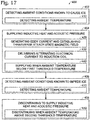
- Yet another example of the subject matter according to the present disclosure relates to a method of impeding formation of ice on an exterior surface of an airfoil.
- the method comprises detecting first ambient conditions known to cause the ice to form on the exterior surface.
- the method also comprises supplying inductive heat and acoustic pressure to the exterior surface when the first ambient conditions are detected.
- the method additionally comprises detecting second ambient conditions known to impede the ice from forming on the exterior surface.
- the method further comprises discontinuing to supply the inductive heat and the acoustic pressure to the exterior surface when the second ambient conditions are detected.
- solid lines, if any, connecting various elements and/or components may represent mechanical, electrical, fluid, optical, electromagnetic and other couplings and/or combinations thereof.
- "coupled” means associated directly as well as indirectly.
- a member A may be directly associated with a member B, or may be indirectly associated therewith, e.g., via another member C. It will be understood that not all relationships among the various disclosed elements are necessarily represented. Accordingly, couplings other than those depicted in the block diagrams may also exist.
- Dashed lines, if any, connecting blocks designating the various elements and/or components represent couplings similar in function and purpose to those represented by solid lines; however, couplings represented by the dashed lines may either be selectively provided or may relate to alternative examples of the present disclosure.
- elements and/or components, if any, represented with dashed lines indicate alternative examples of the present disclosure.
- One or more elements shown in solid and/or dashed lines may be omitted from a particular example without departing from the scope of the present disclosure.
- Environmental elements, if any, are represented with dotted lines. Virtual (imaginary) elements may also be shown for clarity.
- FIGS. 1-16 may be combined in various ways without the need to include other features described in FIGS. 1-16 , other drawing figures, and/or the accompanying disclosure, even though such combination or combinations are not explicitly illustrated herein.
- additional features not limited to the examples presented may be combined with some or all of the features shown and described herein.
- FIGS. 17-19 referred to above, the blocks may represent operations and/or portions thereof and lines connecting the various blocks do not imply any particular order or dependency of the operations or portions thereof. Blocks represented by dashed lines indicate alternative operations and/or portions thereof. Dashed lines, if any, connecting the various blocks represent alternative dependencies of the operations or portions thereof. It will be understood that not all dependencies among the various disclosed operations are necessarily represented.
- FIGS. 17-19 and the accompanying disclosure describing the operations of the method(s) set forth herein should not be interpreted as necessarily determining a sequence in which the operations are to be performed. Rather, although one illustrative order is indicated, it is to be understood that the sequence of the operations may be modified when appropriate. Accordingly, certain operations may be performed in a different order or simultaneously. Additionally, those skilled in the art will appreciate that not all operations described need be performed.
- first, second, etc. are used herein merely as labels, and are not intended to impose ordinal, positional, or hierarchical requirements on the items to which these terms refer. Moreover, reference to, e.g., a “second” item does not require or preclude the existence of, e.g., a "first” or lower-numbered item, and/or, e.g., a "third" or higher-numbered item.
- a system, apparatus, structure, article, element, component, or hardware “configured to” perform a specified function is indeed capable of performing the specified function without any alteration, rather than merely having potential to perform the specified function after further modification.
- the system, apparatus, structure, article, element, component, or hardware “configured to” perform a specified function is specifically selected, created, implemented, utilized, programmed, and/or designed for the purpose of performing the specified function.
- "configured to” denotes existing characteristics of a system, apparatus, structure, article, element, component, or hardware which enable the system, apparatus, structure, article, element, component, or hardware to perform the specified function without further modification.
- a system, apparatus, structure, article, element, component, or hardware described as being “configured to” perform a particular function may additionally or alternatively be described as being “adapted to” and/or as being “operative to” perform that function.
- coordinate frames with an x-axis, a y-axis, and/or a z-axis may be provided.
- the coordinate frames are to assist interpretation of FIGS. 4-16 relative to each other and relative to airfoils 100, 200, and 300.
- the x-axis is generally in the direction of airflow encountered by airfoils 100, 200, and 300.
- the y-axis is perpendicular to the x-axis and generally parallel to leading edges 106, 206, and 306 of respective airfoils 100, 200, and 300.
- the z-axis is perpendicular to the x-axis and the y-axis.
- Airfoil 100 comprises skin 110, comprising external surface 112 and internal surface 114, opposite external surface 112. Skin 110 is magnetically and electrically conductive. Airfoil 100 also comprises interior space 108, formed by skin 110. Internal surface 114 of skin 110 faces interior space 108. Airfoil 100 additionally comprises leading edge 106 along external surface 112 of skin 110. Airfoil 100 further comprises hybrid acoustic induction-heating system 102, configured to impede formation of ice on external surface 112 of skin 110. Hybrid acoustic induction-heating system 102 comprises induction coil 130 within interior space 108.
- Hybrid acoustic induction-heating system 102 also comprises at least one magnet 140 within interior space 108. At least one magnet 140 is configured to produce steady-state magnetic field 182 within skin 110.
- Airfoil 100 is configured to impede, prevent, reduce, and/or remove ice that may form on skin 110. Ice on an airfoil may disturb the aerodynamic flow of air over the airfoil. Use of airfoil 100 may impede, prevent, reduce, and/or remove ice on airfoil 100 and, thus, may eliminate or reduce the effects of ice on airfoil 100. Airfoil 100 is configured to use both inductive heat and acoustic vibrations to impede, prevent, reduce, and/or remove ice on airfoil 100. Inductive heat may be used to increase and/or to maintain the temperature of skin 110, in particular external surface 112 and/or leading edge 106.
- the temperature of skin 110, in particular external surface 112 and/or leading edge 106, to impede, prevent, reduce, and/or to remove ice generally is above the freezing point of water.
- Acoustic vibrations may be used to keep external surface 112, and in particular leading edge 106, non-static (vibrating).
- a static (non-vibrating) structure may be more amenable to ice nucleation, moisture adhesion, and/or heat transfer to moisture particles than a non-static (vibrating) structure.
- the combination of inductive heat and acoustic vibrations may more efficiently impede, prevent, reduce, and/or remove ice from an airfoil than use of either technique alone.
- Airfoil 100 is a body shaped to provide a desired reaction force when in motion relative to a surrounding fluid (e.g., air). Relevant to icing, the fluid may include moisture that may impact airfoil 100 and may tend to form ice on airfoil 100 if hybrid acoustic induction-heating system 102 is not operative.
- Leading edge 106 is the foremost edge of airfoil 100 or an edge that meets the fluid first as airfoil 100 moves therethrough.
- Airfoil 100 includes induction coil 130 and at least one magnet 140 within interior space 108. Hence, induction coil 130 and magnet 140 are not exposed at exterior surface 112 and do not affect the aerodynamic airflow across airfoil 100.
- Skin 110 is magnetically conductive so that a magnetic field is will tend to concentrate within skin 110.
- Skin 110 is magnetically conductive at temperatures near and below the freezing point of water, and above the lowest operating temperature for airfoil 100.
- skin 110 may be a soft magnetic material (easily magnetized and demagnetized) and/or a ferromagnetic material (exhibiting a large, positive, non-linear susceptibility to an external magnetic field).
- Ferromagnetic materials exhibit saturation, a maximum magnetic field (B-field) within the material, and a Curie temperature, the temperature above which the ferromagnetic material does not exhibit spontaneous magnetism.
- materials may be magnetic or non-magnetic.
- Magnetic materials are ferromagnetic.
- ferromagnetic materials include ferrimagnetic materials.
- Magnetic materials and ferromagnetic materials are not necessarily permanent magnets.
- Ferromagnetic materials do not necessarily include iron.
- Non-magnetic materials are paramagnetic (exhibiting a small, positive, substantially linear susceptibility to an external magnetic field) or diamagnetic (exhibiting a small, negative, substantially linear susceptibility to an external magnetic field).
- Skin 110 is electrically conductive so that eddy current 180 will form in skin 110 and so that skin 110 is susceptible to inductive heat.
- Inductive heat heats an electrically conductive object by applying an alternating magnetic field to the object.
- the alternating magnetic field causes eddy current 180 to circulate on the object.
- Eddy current 180 causes resistive heating (also called Joule heating) due to the electrical resistance of the electrically conductive object.
- Eddy current 180 and consequent heat generation are confined generally to a thin surface region of the object characterized by the frequency-dependent skin depth parameter.
- the skin depth also called the electrical skin depth and the electromagnetic skin depth
- the efficiency of inductive heat is related to the intensity and frequency of the alternating magnetic field, the geometry of induction coil 130, the relative size and position of induction coil 130 and skin 110, and the material of skin 110.
- Materials for skin 110 may be selected for suitability as the external surface of an airfoil (e.g., external surface 112 of airfoil 100).
- Properties that may be selected comprise high magnetic permeability (magnetic conductivity), suitable electrical conductivity, strength, environmental resistance, abrasion resistance, and coefficient of temperature variation.
- Induction coil 130 is configured to produce an alternating magnetic field when alternating electrical current 134 is flowing through induction coil 130.
- Induction coil 130 is a coil of wire configured to carry alternating electrical current 134 therethrough.
- the wire is electrically conductive, generally with low resistance (e.g., copper or aluminum wire).
- the wire of induction coil 130 is wound generally in a spiral or helical pattern such that the wire forms parallel loops with sections of parallel wires.
- the loops and the individual wire segments of the parallel wires are electrically isolated such that electrical current follows the path of the wire and does not short between loops or the parallel wires.
- the wire may be a solid conductor, an assembly of individual conductors, and/or an assembly of electrically isolated conductors. For example, higher efficiency alternating electrical current flow (less current crowding) may be achieved by using a Litz wire configuration (a braided assembly of electrically isolated wires used as a single wire).
- Portion 136 of induction coil 130 is a portion of parallel wire of induction coil 130. Generally, portion 136 is a portion of the virtual surface of induction coil.
- the shape of induction coil 130 and portion 136 of induction coil 130 is defined by the exterior form of induction coil.
- induction coil 130 may be formed of a helix of wire.
- the exterior form of a regular helix is a cylinder.
- Such induction coil 130 may be referred to as a cylindrical induction coil.
- Portion 136 of a cylindrical induction coil is a segment of the cylinder that defines the exterior form of the cylindrical induction coil.
- Portion 136 of induction coil 130 is located sufficiently close to internal surface 114 of skin 110 to produce eddy current 180 in skin 110 when alternating electrical current 134 is flowing in induction coil 130.
- induction coil 130 may be called inductively coupled to skin 110. If induction coil 130 and portion 136 of induction coil 130 are not sufficiently close to skin 110 and internal surface 114 of skin 110, no significant eddy current 180 will be produced in skin 110 and therefore induction coil 130 would not be positioned to inductively heat skin 110.
- Magnet 140 is configured to produce steady-state magnetic field 182 (also referred to as a DC magnetic field) within skin 110. Magnet 140 also may be referred to as magnetic source. Steady-state magnetic field 182 generally interacts with electrical currents (such as eddy current 180) within skin 110 to produce force 184 (Lorentz force) within skin 110. The Lorenz force is proportional to the cross product of the velocity of a charged particle (such as an electron) and the magnetic field (B field), in the absence of an applied electric field. Force 184 due to alternating electrical currents (such as eddy current 180) within skin 110 interacting with steady-state magnetic field 182 within skin 110 produces acoustic vibrations within skin 110 (at twice the frequency of the alternating electrical current).
- Force 184 is absent (or zero) when eddy current 180 within skin 110 and steady-state magnetic field 182 are parallel. All other things being equal, force 184 is a maximum when eddy current 180 within skin 110 and steady-state magnetic field 182 are perpendicular.
- eddy current 180 is generated in skin 110 to inductively heat skin 110 directly, without requiring thermal contact to a heat source (e.g., no heating element is required).
- the interaction of eddy current 180 with steady-state magnetic field 182 generates force 184 and acoustic vibrations directly in skin 110, without requiring acoustic contact to a sound source (e.g., no acoustic transducer such as piezoelectric element is required).
- acoustic refers to sound waves and may indicate audible (e.g., sonic) and/or inaudible (e.g., ultrasonic, infrasonic) frequencies. Higher frequencies have shorter wavelengths.
- the acoustic frequency (and the alternating electrical current frequency) may affect the efficiency of impeding, preventing, reducing, and/or removing ice from airfoil 100. Generally higher frequencies produce a more capable acoustic wave (i.e., generation of acoustic pressure is more efficient).
- magnet 140 is within interior space 108 of airfoil 100 and skin 110 is magnetically conductive (and/or ferromagnetic), most or all of the resultant magnetic field (such as steady-state magnetic field 182) is contained within airfoil 100. Magnetic field lines that would otherwise extend beyond skin 110, if skin 110 were not present (or not magnetically conductive and/or ferromagnetic), are substantially redirected within skin 110. Thus, little to no magnetic field from magnet 140 is present outside of airfoil 100. Hence, special precautions for operating near high magnetic fields are not needed for personnel, tools, or equipment operating outside of airfoil 100.
- Steady-state magnetic field 182 may be a permanent magnetic field (e.g., from permanent magnet 142), or may be controllable (e.g., from electromagnet 144). Where controllable, steady-state magnetic field 182 may be turned on or off as desired to actuate the acoustic vibrations in skin 110. In addition to controlling acoustic vibrations, a controllable steady-state magnetic field may be turned off to eliminate high magnetic fields within airfoil 100. Thus, special precautions for operating near high magnetic fields within airfoil 100 may be avoided.
- example 2 also includes the subject matter according to example 1, above.
- steady-state magnetic field 182 produced by at least one magnet 140, is transverse to eddy current 180.
- Eddy current 180 is the result alternating electrical current 134 flowing in induction coil 130.
- Eddy current 180 may be represented as one or more mirror currents (virtual currents) within skin 110 that flow in the opposite direction of (and at the same frequency as) alternating electrical current 134 and at a position in skin 110 that is a mirror image of the position of the parallel wires carrying alternating electrical current 134 (with respect to internal surface 114).
- eddy current 180 is transverse to steady-state magnetic field 182
- moving charges that make up eddy current 180 experience force 184.
- the force 184 on eddy current 180 results in acoustic vibrations in skin 110 (at twice the frequency of eddy current 180 and twice the frequency of alternating electrical current 134).
- transverse means not parallel. Transverse arrangements encompass perpendicular arrangements.
- induction coil 130 has a sheet form.
- a sheet-form induction coil also may be referred to as a flat induction coil, a pancake induction coil, and/or a planar induction coil.
- the wire of the induction coil is spiraled into the shape of a substantially two-dimensional (2D) surface.
- the virtual 2D surface does not need to be a plane or flat.
- the virtual 2D surface may be a surface of a virtual three-dimensional (3D) structure such as the shape of the interior of airfoil 100, interior space 108, and/or internal surface 114 of skin 110.
- a sheet-form induction coil produces a magnetic field perpendicular to the sheet, at the core of the sheet-form induction coil (center of the spiral of wire). Sheet-form induction coils have high inductive coupling to skin 110 on opposite sides of the sheet that defines the shape of the sheet-form induction coil.
- induction coil 130 has a volumetric form.
- a volumetric-form induction coil is a coil that encloses a core volume with the center of the spiral of wire within the core volume.
- a sheet-form induction coil may or may not enclose a core volume (e.g., a sheet-form induction coil may conform to the shape of a cylindrical shell) but the center of the spiral of wire is within the sheet.
- a volumetric-form coil would be substantially tube-like with the wire spiraled around the outside of the virtual tube (e.g., the classical shape of a wire-wound inductor).
- a volumetric-form induction coil produces a magnetic field parallel to the center of the spiral of wire and generally parallel to the longitudinal axis of the enclosed volume.
- example 5 also includes the subject matter according to any one of examples 1 to 4, above.
- at least portion 136 of induction coil 130 is no more than 10mm away from internal surface 114 of skin 110.
- Portion 136 of induction coil 130 is proximate to skin 110 and internal surface 114 of skin 110.
- portion 136 of induction coil 130 may be better inductively coupled to skin 110 and/or may produce stronger eddy current 180.
- the distance between portion 136 of induction coil 130 and internal surface 114 of skin 110 affects the efficiency of applying inductive and acoustic pressure (also referred to as acoustic energy) within skin 110.
- example 6 also includes the subject matter according to example 5, above.
- at least portion 136 of induction coil 130 is no more than 1mm away from internal surface 114 of skin 110.
- portion 136 of induction coil 130 is very close to internal surface 114 of skin 110.
- portion 136 may be within a small integer multiple of the thickness of skin 110 and/or within a small integer multiple of the skin depth of the material of skin 110 at the frequency of alternating electrical current 134.
- example 7 also includes the subject matter according to any one of examples 1 to 6, above.
- at least portion 136 of induction coil 130 is parallel to skin 110.
- Portion 136 of induction coil 130 may be located parallel to skin 110 to provide a substantially constant distance between skin 110 (i.e., internal surface 114 of skin 110) and portion 136 of induction coil 130.
- the constant distance may provide a substantially uniform coupling efficiency for inductive heat and/or a substantially uniform eddy current 180 across skin 110 that is parallel to portion 136.
- Portion 136 and/or substantially all of induction coil 130 (e.g., where induction coil 130 has a sheet form) may be substantially conformal to internal surface 114 of skin 110.
- airfoil 100 is selected from the group consisting of a wing, an erosion shield, an empennage, a horizontal stabilizer, a vertical stabilizer, a winglet, a turbine-engine inlet, an engine nacelle, and a turbine blade.
- Airfoil 100 may be a portion of an aircraft or other structure with aerodynamic surfaces. Such aircraft or structures may include one or more airfoils 100 and may include other aerodynamic surfaces that are not airfoils 100. Use of airfoils 100 on an aircraft or other structure may protect that aircraft or structure from the effects of ice formation.
- An erosion shield is a section of an aerodynamic surface configured to resist erosion due to air flow impinging the leading edge of the aerodynamic surface. An erosion shield may form all or a substantial portion of a leading edge such as leading edge 106.
- An empennage may include a horizontal stabilizer and/or a vertical stabilizer. A common empennage configuration includes a single vertical stabilizer and a pair of horizontal stabilizers. Horizontal stabilizers are not necessarily horizontal when the corresponding aircraft is resting in a parked configuration on the ground. Vertical stabilizers are not necessarily vertical when the corresponding aircraft is resting in a parked configuration on the ground.
- example 9 also includes the subject matter according to any one of examples 1 to 8, above.
- at least portion 136 of induction coil 130 is closer to leading edge 106 than any other portion of induction coil 130 and is positioned to heat leading edge 106.
- induction coil 130 is positioned to heat and to apply acoustic pressure to leading edge 106 and regions of external surface 112 proximate to leading edge 106.
- ice formation and/or accumulation effects are strong at and near the leading edge of an aerodynamic structure.
- example 10 also includes the subject matter according to any one of examples 1 to 9, above.
- at least portion 136 of induction coil 130 is transverse to leading edge 106.
- Portion 136 of induction coil 130 is transverse to leading edge 106 when the parallel wires in portion 136 are transverse to leading edge 106.
- the direction of the parallel wires defines the direction of eddy current 180 within skin 110.
- eddy current 180 due to portion 136 of induction coil 130 with alternating current 134 flowing therethrough is transverse to leading edge 106.
- force 184 is perpendicular to eddy current 180
- force 184 in this arrangement, may be perpendicular to leading edge 106 (i.e., in the x-direction) or parallel to leading edge 106 (i.e., in the y-direction).
- example 11 also includes the subject matter according to any one of examples 1 to 9, above.
- at least portion 136 of induction coil 130 is parallel to leading edge 106.
- Portion 136 of induction coil 130 is parallel to leading edge 106 when the parallel wires in portion 136 are parallel to leading edge 106.
- the direction of the parallel wires defines the direction of eddy current 180 within skin 110.
- eddy current 180 due to portion 136 of induction coil 130 with alternating current 134 flowing therethrough is parallel to leading edge 106.
- force 184 is perpendicular to eddy current 180
- force 184 in this arrangement, may be perpendicular to leading edge 106 (e.g., in the x-direction or the z-direction).
- example 12 also includes the subject matter according to any one of examples 1 to 11, above.
- at least one magnet 140 is permanent magnet 142.
- Permanent magnet 142 produces a magnetic field without electronics or electrical current flow. Hence, use of permanent magnet 142 may simplify construction and/or control of airfoil 100 and/or hybrid acoustic induction-heating system 102.
- example 13 also includes the subject matter according to any one of examples 1 to 12, above.
- at least one magnet 140 is electromagnet 144.
- Electromagnet 144 produces steady-state magnetic field 182 when a steady-state (direct current, DC) electrical current flows through a coil.
- the magnetic field may be turned on or off by controlling the electrical current flow. Additionally or alternatively, the magnetic field strength and direction may be adjusted according to the electrical current flow.
- Electromagnet 144 generally is controllable and may be referred to as a controllable magnet.
- Induction coil 130 may serve as the coil of electromagnet 144.
- Induction coil 130 may be adapted to flow steady-state electrical current so that induction coil 130 may produce steady-state magnetic field 182.
- the steady-state electrical current to produce steady-state magnetic field 182 is typically much greater (has a much greater magnitude) than the amplitude of alternating electrical current 134.
- induction coil 130 adapted to flow steady-state electrical current may have wires with a higher cross section (lower resistance) than corresponding wires of induction coil 130 that is adapted to flow only alternating electrical current 134.
- example 14 also includes the subject matter according to any one of examples 1 to 13, above.
- at least one magnet 140 is a plurality of magnets.
- the plurality of magnets may be arranged to position and/or direct steady-state magnetic field 182 to generate force 182 in suitable positions and/or directions.
- At least one magnet 140 may comprise one or more permanent magnets 142 and/or one or more electromagnets 144.
- example 15 also includes the subject matter according to any one of examples 1 to 14, above.
- steady-state magnetic field 182 produced by at least one magnet 140, is transverse to at least portion 136 of induction coil 130.
- Steady-state magnetic field 182 is transverse to portion 136 of induction coil 130 when steady-state magnetic field 182 is transverse to the parallel wires of portion 136.
- Steady-state magnetic field 182 forms loops of magnetic field lines (as do all magnetic fields).
- the direction is specified at the location of the corresponding structure, unless otherwise explicitly stated.
- steady-state magnetic field 182 is transverse to portion 136 of induction coil 130 at portion 136 of induction coil 130.
- steady-state magnetic field 182 at the parallel wires of portion 136 is transverse to the parallel wires of portion 136.
- the direction of parallel wires of induction coil 130 determines the direction of eddy currents 180 within skin 110. Generating steady-state magnetic field 182 transverse to portion 136 generally produces steady-state magnetic field 182 transverse to eddy current 180. Steady-state magnetic field 182 being transverse to eddy current 180 generates force 184.
- example 16 also includes the subject matter according to any one of examples 1 to 15, above.
- steady-state magnetic field 182 produced by at least one magnet 140, is transverse to skin 110 at internal surface 114 of skin 110.
- Eddy current 180 is within skin 110 and hence is substantially parallel to skin 110.
- Steady-state magnetic field 182 is transverse to eddy current 180 when also transverse to internal surface 114 of skin 110.
- Steady-state magnetic field 182 being transverse to eddy current 180 generates force 184.
- example 17 also includes the subject matter according to any one of examples 1 to 16, above.
- steady-state magnetic field 182 produced by at least one magnet 140, is transverse to a portion of internal surface 114 of skin 110 that is closest to leading edge 106.
- Portion of internal surface 114 of skin 110 that is closest to leading edge 106 also may be referred to as the portion of internal surface 114 that is directly opposite, directly behind, and/or directly downstream of leading edge 106.
- Leading edge 106 is on external surface 112 of skin 110.
- a position on internal surface 114 of skin 110 that is closest to leading edge 106 is a position on internal surface 114 that is separated by leading edge 106 by the thickness of skin 110.
- the distance between a point, line, and/or plane to another point, line, and/or plane is the geometric distance between the objects, which is the shortest perpendicular distance.
- example 18 also includes the subject matter according to any one of examples 1 to 16, above.
- steady-state magnetic field 182 produced by at least one magnet 140, is parallel to leading edge 106 at a portion of internal surface 114 of skin 110 that is closest to leading edge 106.
- example 19 also includes the subject matter according to any one of examples 1 to 18, above.
- steady-state magnetic field 182, produced by at least one magnet 140 has a magnitude greater than 0.1T (tesla) and less than 100T.
- Steady-state magnetic field 182 is sufficiently strong so as to cause significant acoustic pressure in skin 110 when steady-state magnetic field 182 interacts with eddy current 180 caused by alternating electrical current 134 in induction coil 130.
- Steady-state magnetic field 182 may be a strong magnetic field, with a magnitude greater than 0.1T, and a magnetic field that is practical to generate with permanent magnet 142 or electromagnet 144 within airfoil 100.
- airfoil 100 further comprises control system 150.
- Skin 110 has controlled region 116, in which eddy current 180 is produced when alternating electrical current 134 is flowing in induction coil 130.
- Control system 150 is configured to supply alternating electrical current 134 to induction coil 130 to generate inductive heat and acoustic pressure in controlled region 116 of skin 110.
- Control system 150 may be used to control the amount and timing of generation of inductive heat and acoustic pressure to impede, to prevent, to reduce, and/or to remove ice on airfoil 100.
- control system 150 is configured to supply alternating electrical current 134 based, at least in part, on an ambient temperature of layer of fluid 118 flowing over external surface 112 of skin 110.
- Layer of fluid 118 flowing over external surface 112 of skin 110 generally is air that may include moisture.
- moisture from the fluid may accumulate on external surface 112 of skin 110 as ice, e.g., moisture may freeze on contact with external surface 112 of skin 110.
- controlling the supply of alternating electrical current 134 based on the ambient temperature permits selectively applying inductive heat and acoustic pressure when ambient conditions may cause icing.
- airfoil 100 further comprises temperature sensor 160, configured to measure the ambient temperature of layer of fluid 118 flowing over external surface 112 of skin 110.
- Temperature sensor 160 is configured to measure the ambient temperature and configured such that control system 150 may determine the ambient temperature through use of temperature sensor. For example, temperature sensor 160 may transfer a signal representative of the ambient temperature to control system 150. Temperature sensor 160 may be configured to measure ambient temperature directly or indirectly. For example, temperature sensor 160 may be in direct thermal contact with layer of fluid 118 flowing over external surface 112 of skin 110. As another example, temperature sensor 160 may be configured to measure the temperature of a portion of external surface 112 of skin 110, which is in thermal contact with layer of fluid 118 flowing over external surface 112. Examples of temperature sensors 160 include a thermocouple, a resistance temperature detector, an infrared sensor, and a thermistor. Additionally or alternatively, one or more temperature sensors 160 may be remote from airfoil 100 and configured to measure a temperature characteristic of and/or related to the ambient temperature of layer of fluid 118 flowing over external surface 112 of skin 110.
- control system 150 is configured to supply alternating electrical current 134 to induction coil 130 based, at least in part, on an ambient temperature at an altitude of airfoil 100.
- Ambient temperature at the altitude of airfoil 100 may be characteristic of and/or related to the ambient temperature of the layer of fluid flowing over external surface 112 of skin 110. Hence, controlling the supply of alternating electrical current 134 based on the ambient temperature at the altitude of airfoil 110 permits selectively applying inductive heat and acoustic pressure when the ambient conditions may cause icing.
- altitude refers to elevation above sea level, and may be referred to as true altitude.
- the elevation above the ground below an elevated structure such as an aircraft may be referred to as absolute altitude to distinguish absolute altitude from altitude (true altitude).
- alternating electrical current 134 has a frequency that is at least 100kHz (kilohertz) and at most 10MHz (megahertz).
- the frequency of alternating electrical current 134 affects the skin depth of inductive heat as discussed above. Higher frequencies have thinner skin depths. Efficiency of inductive heat improves when the skin depth is similar to the thickness of skin 110.
- the frequency of alternating electrical current 180 may be selected to produce skin depth that is a small integer divisor of the thickness of skin 110 (e.g., a skin depth of 1 ⁇ 2 to 1 ⁇ 4 of the thickness of skin 110).
- the frequency of alternating electrical current 134 is the frequency of eddy current 180 and half the frequency of the acoustic pressure generated by eddy current 180 interacting with steady-state magnetic field 182. Higher frequencies may lead to more efficient acoustic ice impediment, prevention, reduction, and/or removal.
- the frequency of alternating electrical current 134 may be selected to tune (e.g., to balance) the effects of inductive heat and acoustic pressure on ice impediment, prevention, reduction, and/or removal from airfoil 100.
- example 25 also includes the subject matter according to example 24, above.
- the frequency of alternating electrical current 134 is at least 1MHz.
- Higher frequencies such as a frequency at least 1MHz, may emphasize the effects of acoustic pressure over the effects of inductive heat.
- example 26 also includes the subject matter according to any one of examples 20 to 25, above.
- alternating electrical current 134 generates alternating magnetic field 186 with an amplitude that is less than a magnitude of steady-state magnetic field 182.
- Alternating magnetic field 286 generates eddy current 180 within skin 110, with the amplitude of eddy current 180 related to the amplitude of alternating magnetic field 186.
- the amplitude of eddy current 180 affects the efficiency of inductive heat.
- the magnitude of steady-state magnetic field 182 affects the amplitude of force 184 that acts on skin 110 to produce acoustic pressure.
- the relative size of the amplitude of alternating magnetic field 186 and the magnitude of steady-state magnetic field 182 affects the relative contributions of inductive heat and acoustic pressure to impeding, preventing, reducing, and/or removing ice from airfoil 100.
- inductive heat would be more efficient that force generation.
- example 27 also includes the subject matter according to example 26, above.
- a ratio of the amplitude of alternating magnetic field 186 to the magnitude of steady-state magnetic field 182 is less than 0.1 and greater than 0.0001.
- the amplitude of alternating magnetic field 186 may be much smaller than the magnitude of steady-state magnetic field 182 to produce a system in which acoustic pressure has a significant, or more significant, contribution to impeding, preventing, reducing, and/or removing ice from airfoil 100.
- control system 150 comprises power supply 154 and controller 152.
- Power supply 154 is configured to supply alternating electrical current 134 to induction coil 130.
- Controller 152 is programmed to receive signals, representative of first ambient conditions known to cause formation of the ice on external surface 112 of skin 110 and second ambient conditions known to impede formation of the ice on external surface 112.
- the first ambient conditions and the second ambient conditions both comprise an ambient temperature of layer of fluid 118 flowing over external surface 112 of skin 110.
- Controller 152 is programmed to cause power supply 154 to supply alternating electrical current 134 to induction coil 130 to generate inductive heat and acoustic pressure in controlled region 116 of skin 110, based upon the first ambient conditions. Controller 152 is programmed to cause power supply 154 to discontinue supplying alternating electrical current 134 to induction coil 130, based upon the second ambient conditions.
- Power supply 154 is configured to selectively supply alternating electrical current 134 to induction coil 130, thereby selectively producing eddy current 180, inductive heat, and/or acoustic pressure in skin 110.
- Controller 152 may be configured to turn on and off power supply 154 and thus to control the application of inductive heat and acoustic pressure based upon ambient conditions (e.g., first ambient conditions and second ambient conditions) which may otherwise cause ice to form or impede ice from forming on external surface 112 of skin 110.
- Controller 152 may be a computer (e.g., comprising a processor and memory) and/or dedicated hardware. Controller 152 may implement its functions (e.g., receiving signals, causing power supply 154 to supply current, and causing power supply 154 to discontinue supplying current) in software, firmware, and/or hardware. Controller 152 may be referred to as an embedded computer and/or an embedded system.
- controller 152 is also programmed to cause power supply 154 to supply alternating electrical current 134 to induction coil 130 when the ambient temperature of layer of fluid 118 flowing over external surface 112 of skin 110 is below a first threshold temperature.
- Controller 152 may be configured to cause power supply 154 to supply current based on the ambient temperature being below a first threshold temperature such as a temperature known to permit ice to accumulate on external surface 112 of airfoil 100.
- the first threshold temperature may be a predetermined threshold or may be a function of other parameters (e.g., the temperature of external surface 112 of airfoil 100, humidity, operation time of hybrid acoustic induction-heating system 102, etc.).
- example 30 also includes the subject matter according to example 29, above.
- the first threshold temperature is above freezing point of water and below 5°C.
- the temperature range from the freezing point of water to 5°C is a range in which water impacting airfoil 100 may transition from remaining liquid to accumulating as ice.
- the first threshold being within this range is a reasonable predictor of the need to turn on the inductive heat and acoustic pressure to impede, to prevent, to reduce, and/or to remove ice from airfoil 100.
- controller 152 is also programmed to cause power supply 154 to discontinue supplying alternating electrical current 134 to induction coil 130 when the ambient temperature of layer of fluid 118 flowing over external surface 112 of skin 110 is above a second threshold temperature.
- Controller 152 may be configured to cause power supply 154 to discontinue supplying current based on the ambient temperature being above a second threshold temperature such as a temperature known to not significantly permit ice to accumulate on external surface 112 of airfoil 100.
- the second threshold temperature may be a predetermined threshold or may be a function of other parameters (e.g., the temperature of external surface 112 of airfoil 100, humidity, operation time of hybrid acoustic induction-heating system 102, etc.).
- example 32 also includes the subject matter according to example 31, above.
- the second threshold temperature is different than the first threshold temperature.
- the second threshold temperature value may be the same as or different than the first threshold temperature value. Different values for the second threshold temperature and the first threshold temperature permit the controller to turn on or off the inductive heat and acoustic pressure at different temperatures.
- example 33 also includes the subject matter according to any one of examples 31 to 32, above.
- the second threshold temperature is greater than the first threshold temperature.
- the second threshold temperature being higher than the first threshold temperature tends to prevent oscillation in the turning on and turning off of the inductive heat and acoustic pressure. If the second threshold temperature is the same as the first threshold temperature, small variations in the ambient temperature about the single temperature threshold may cause to controller 152 to command power supply 154 in contrary manners in rapid succession. If by supplying alternating electrical current 134, the ambient temperature is increased, the act of causing power supply 154 to supply current could cause the ambient temperature to rise and thereby cause controller 152 to cause power supply 154 to discontinue supplying current, with the likely consequence of reducing the ambient temperature. Such conditions could cause controller 152 and hybrid acoustic induction-heating system 102 to oscillate and ineffectively supply inductive heat and acoustic pressure.
- example 34 also includes the subject matter according to any one of examples 31 to 33, above.
- the second threshold temperature is above 2°C and below 10°C.
- the temperature range from above 2°C to below 10°C is a range in which water impacting airfoil 100 may transition from accumulating as ice to remaining liquid.
- the second threshold being within this range is a reasonable predictor of the need to turn off the inductive heat and acoustic pressure to impede, to prevent, to reduce, and/or to remove ice from airfoil 100.
- example 35 of the present disclosure, wherein example 35 also includes the subject matter according to any one of examples 1 to 34, above.
- skin 110 comprises a nickel-iron alloy.
- Nickel-iron alloys are a class of alloys that are suitable for skin 110. Nickel-iron alloys are electrically and magnetically conductive, and are susceptible to inductive heat and acoustic pressure generation. Nickel-iron alloys consist primarily of nickel and iron. Concentrations of nickel may be about 20% to about 90%. Concentrations of iron may be about 10% to about 80%. Examples of specific nickel-iron alloys include MU-METAL-brand alloy, PERMALLOY-brand alloy, HYMU 80-brand alloy, and INVAR-brand alloy.
- example 36 also includes the subject matter according to any one of examples 1 to 35, above.
- skin 110 has a thickness of less than 1mm and greater than 0.001mm.
- Skin 110 generally is thin so that skin 110 may be affected rapidly by the inductive heat and acoustic pressure generated by hybrid acoustic induction-heating system 102.
- the thickness of skin 110 may be selected based on practical and/or desired frequencies of alternating electrical current 134 and/or skin depth at those frequencies. Skin 110 is thick enough to maintain structural integrity when subjected to conditions of airfoil 100.
- example 37 also includes the subject matter according to any one of examples 1 to 36, above.
- skin 110 is ferromagnetic.
- skin 110 may be ferromagnetic to concentrate magnetic fields within skin 110.
- example 38 of the present disclosure also includes the subject matter according to any one of examples 1 to 37, above.
- skin 110 has relative magnetic permeability of greater than 1,000 and less than 10,000,000.
- Magnetic materials have a relative magnetic permeability significantly greater than unity.
- Non-magnetic materials have a relative magnetic permeability near unity. Higher relative magnetic permeabilities indicate a higher affinity for and concentration of magnetic fields within the material.
- Typical magnetic materials have a relative magnetic permeability greater than about 100.
- Highly magnetic materials have a relative magnetic permeability of greater than about 1,000. All known materials have a relative magnetic permeability of less than 10,000,000.
- example 39 also includes the subject matter according to any one of examples 1 to 38, above.
- Curie temperature of skin 110 is less than 300°C and greater than 50°C.
- the Curie temperature is a transition temperature of ferromagnetic materials. Below the Curie temperature, the material has a high relative magnetic permeability. Above the Curie temperature, the material is paramagnetic with a lower relative magnetic permeability. If skin 110 becomes paramagnetic (as opposed to ferromagnetic or magnetically conductive at a particular temperature), the efficiency of inductive heat and/or generation of acoustic pressure will be significantly reduced.
- hybrid acoustic induction-heating system 102 may be configured to automatically cease significant induction-heating and/or acoustic pressure generation if skin 110 becomes too hot (e.g., in the event of a malfunction of hybrid acoustic induction-heating system 102 or excessive solar heating of airfoil 100).
- airfoil 100 further comprises electrical insulator 120 in interior space 108. Electrical insulator 120 is coupled to skin 110.
- Airfoil 100 may be heated and/or subject to acoustic pressure in a similar manner as skin 110. Hence, forms, supports, and other structures within airfoil 100 may be electrically insulating and/or located sufficiently far away from induction coil 130 and/or magnet 140.
- example 41 also includes the subject matter according to example 40, above.
- electrical insulator 120 supports skin 110.
- Airfoils 100 may be constructed with an internal support, such as electrical insulator 120, to support skin 110 and/or induction coil 130, and/or to maintain the aerodynamic shape of airfoil 100.
- an internal support such as electrical insulator 120, to support skin 110 and/or induction coil 130, and/or to maintain the aerodynamic shape of airfoil 100.
- example 42 also includes the subject matter according to any one of examples 40 to 41, above.
- electrical insulator 120 supports at least one magnet 140.
- Magnet(s) 140 may be supported by internal structure, such as electrical insulator 120, so that magnet(s) 140 is held in a fixed position relative to skin 110 and/or induction coil 130.
- Airfoil 200 comprises skin 210, comprising external surface 212 and internal surface 214, opposite external surface 212. Skin 210 is magnetically and electrically conductive and has controlled region 216. Airfoil 200 also comprises interior space 208, formed by skin 210. Internal surface 214 of skin 210 faces interior space 208. Airfoil 200 additionally comprises leading edge 206 along external surface 212 of skin 210. Airfoil 200 further comprises hybrid acoustic induction-heating system 202, configured to impede formation of ice on external surface 212 of skin 210.
- Hybrid acoustic induction-heating system 202 comprises induction coil 230 within interior space 208. At least portion 236 of induction coil 230 is sufficiently close to internal surface 214 of skin 210 to produce eddy current 280 within controlled region 216 of skin 210 when alternating electrical current 234 is flowing in induction coil 230.
- Hybrid acoustic induction-heating system 202 also comprises control system 250, configured to generate inductive heat and acoustic pressure in controlled region 216 of skin 210 by supplying alternating electrical current 234 to induction coil 230 based, at least in part, on an ambient temperature of layer of fluid 218 flowing over external surface 212 of skin 210.
- Airfoil 200 is configured to impede, prevent, reduce, and/or remove ice that may form on skin 210. Ice on an airfoil may disturb the aerodynamic flow of air over the airfoil. Use of airfoil 200 may impede, prevent, reduce, and/or remove ice on airfoil 200 and, thus, may eliminate or reduce the effects of ice on airfoil 200. Airfoil 200 is configured to use both inductive heat and acoustic vibrations to impede, prevent, reduce, and/or remove ice on airfoil 200. Inductive heat may be used to increase and/or to maintain the temperature of skin 210, in particular external surface 212 and/or leading edge 206.
- the temperature of skin 210, in particular external surface 212 and/or leading edge 206, to impede, prevent, reduce, and/or to remove ice generally is above the freezing point of water. Acoustic vibrations may be used to keep external surface 212, and in particular leading edge 206, non-static (vibrating).
- Airfoil 200 is a body shaped to provide a desired reaction force when in motion relative to a surrounding fluid (e.g., air). Relevant to icing, the fluid may include moisture that may impact airfoil 200 and may tend to form ice on airfoil 200 if hybrid acoustic induction-heating system 202 is not operative.
- Leading edge 206 is the foremost edge of airfoil 200 or an edge that meets the fluid first as airfoil 200 moves therethrough.
- Airfoil 200 includes induction coil 230 within interior space 208. Hence, induction coil 230 is not exposed at exterior surface 212 and does not affect the aerodynamic airflow across airfoil 200.
- Skin 210 is magnetically conductive so that a magnetic field is will tend to concentrate within skin 210.
- Skin 210 is magnetically conductive at temperatures near and below the freezing point of water, and above the lowest operating temperature for airfoil 200.
- skin 210 may be a soft magnetic material (easily magnetized and demagnetized) and/or a ferromagnetic material (exhibiting a large, positive, non-linear susceptibility to an external magnetic field).
- Skin 210 is electrically conductive so that eddy current 280 will form in skin 210 and so that skin 210 is susceptible to inductive heat.
- Inductive heat heats an electrically conductive object by applying an alternating magnetic field to the object.
- the alternating magnetic field causes eddy current 280 to circulate on the object.
- Eddy current 280 causes resistive heating (also called Joule heating) due to the electrical resistance of the electrically conductive object.
- Eddy current 280 and consequent heat generation are confined generally to a thin surface region of the object characterized by the frequency-dependent skin depth parameter.
- the skin depth also called the electrical skin depth and the electromagnetic skin depth
- the efficiency of inductive heat is related to the intensity and frequency of the alternating magnetic field, the geometry of induction coil 230, the relative size and position of induction coil 230 and skin 210, and the material of skin 210.
- Materials for skin 210 may be selected for suitability as the external surface of an airfoil (e.g., external surface 212 of airfoil 200).
- Properties that may be selected comprise high magnetic permeability (magnetic conductivity), suitable electrical conductivity, strength, environmental resistance, abrasion resistance, and coefficient of temperature variation.
- Induction coil 230 is configured to produce an alternating magnetic field when alternating electrical current 234 is flowing through induction coil 230.
- Induction coil 230 is a coil of wire configured to carry alternating electrical current 234 therethrough.
- the wire is electrically conductive, generally with low resistance (e.g., copper or aluminum wire).
- the wire of induction coil 230 is wound generally in a spiral or helical pattern such that the wire forms parallel loops with sections of parallel wires.
- the loops and the individual wire segments of the parallel wires are electrically isolated such that electrical current follows the path of the wire and does not short between loops or the parallel wires.
- the wire may be a solid conductor, an assembly of individual conductors, and/or an assembly of electrically isolated conductors. For example, higher efficiency alternating electrical current flow (less current crowding) may be achieved by using a Litz wire configuration (a braided assembly of electrically isolated wires used as a single wire).
- Portion 236 of induction coil 230 is a portion of parallel wire of induction coil 230. Generally, portion 236 is a portion of the virtual surface of induction coil.
- the shape of induction coil 230 and portion 236 of induction coil 230 is defined by the exterior form of induction coil.
- induction coil 230 may be formed of a helix of wire.
- the exterior form of a regular helix is a cylinder.
- Such induction coil 230 may be referred to as a cylindrical induction coil.
- Portion 236 of a cylindrical induction coil is a segment of the cylinder that defines the exterior form of the cylindrical induction coil.
- Portion 236 of induction coil 230 is located sufficiently close to internal surface 214 of skin 210 to produce eddy current 280 within controlled region 216 of skin 210 when alternating electrical current 234 is flowing in induction coil 230.
- induction coil 230 may be called inductively coupled to skin 210. If induction coil 230 and portion 236 of induction coil 230 are not sufficiently close to skin 210 and internal surface 214 of skin 210, no significant eddy current 280 will be produced in skin 210 and therefore induction coil 230 would not be positioned to inductively heat skin 210.
- Control system 250 may be used to control the amount and timing of generation of inductive heat and acoustic pressure to impede, to prevent, to reduce, and/or to remove ice on airfoil 200, in controlled region 216 of skin 210.
- Control system 250 controls the supply of alternating electrical current 234 to supply alternating electrical current 234 to induction coil 230 to generate inductive heat and acoustic pressure.
- alternating electrical current 234 in induction coil 230 By use of alternating electrical current 234 in induction coil 230, eddy current 280 is generated in skin 210 to inductively heat skin 210 directly, without requiring thermal contact to a heat source (e.g., no heating element is required).
- Control system 250 controls generation of inductive heat and acoustic pressure based on the ambient temperature of layer of fluid 218 flowing over external surface 212 of skin 210.
- Layer of fluid 218 generally is air that may include moisture.
- moisture from the fluid may accumulate on external surface 212 of skin 210 as ice, e.g., moisture may freeze on contact with external surface 212 of skin 210.
- controlling the supply of alternating electrical current 234 based on the ambient temperature permits selectively applying inductive heat and acoustic pressure when ambient conditions may cause icing.
- induction coil 230 has a sheet form.
- a sheet-form induction coil also may be referred to as a flat induction coil, a pancake induction coil, and/or a planar induction coil.
- the wire of the induction coil is spiraled into the shape of a substantially two-dimensional (2D) surface.
- the virtual 2D surface does not need to be a plane or flat.
- the virtual 2D surface may be a surface of a virtual three-dimensional (3D) structure, such as the shape of the interior of airfoil 200, interior space 208, and/or internal surface 214 of skin 210.
- a sheet-form induction coil produces a magnetic field perpendicular to the sheet, at the core of the sheet-form induction coil (center of the spiral of wire). Sheet-form induction coils have high inductive coupling to skin 210 on opposite sides of the sheet that defines the shape of the sheet-form induction coil.
- example 45 of the present disclosure, wherein example 45 also includes the subject matter according to any one of examples 43 to 44, above.
- induction coil 230 has a volumetric form.
- a volumetric-form induction coil is a coil that encloses a core volume with the center of the spiral of wire within the core volume.
- a sheet-form induction coil may or may not enclose a core volume (e.g., a sheet-form induction coil may conform to the shape of a cylindrical shell) but the center of the spiral of wire is within the sheet.
- a volumetric-form coil would be substantially tube-like with the wire spiraled around the outside of the virtual tube (e.g., the classical shape of a wire-wound inductor).
- a volumetric-form induction coil produces a magnetic field parallel to the center of the spiral of wire and generally parallel to the longitudinal axis of the enclosed volume.
- example 46 also includes the subject matter according to any one of examples 43 to 45, above.
- at least portion 236 of induction coil 230 is no more than 10mm away from internal surface 214 of skin 210.
- Portion 236 of induction coil 230 is proximate to skin 210 and internal surface 214 of skin 210.
- portion 236 of induction coil 230 may be better inductively coupled to skin 210 and/or may produce stronger eddy current 280.
- the distance between portion 236 of induction coil 230 and internal surface 214 of skin 210 affects the efficiency of applying inductive and acoustic pressure (also referred to as acoustic energy) within skin 210.
- example 47 also includes the subject matter according to example 46, above.
- at least portion 236 of induction coil 230 is no more than 1mm away from internal surface 214 of skin 210.
- portion 236 of induction coil 230 is very close to internal surface 214 of skin 210.
- portion 236 may be within a small integer multiple of the thickness of skin 210 and/or within a small integer multiple of the skin depth of the material of skin 210 at the frequency of alternating electrical current 234.
- example 48 also includes the subject matter according to any one of examples 43 to 47, above.
- FIG. 2 and particularly to, e.g., FIGS. 10-13 , at least portion 236 of induction coil 230 is parallel to skin 210.
- Portion 236 of induction coil 230 may be located parallel to skin 210 to provide a substantially constant distance between skin 210 (i.e., internal surface 214 of skin 210) and portion 236 of induction coil 230.
- the constant distance may provide a substantially uniform coupling efficiency for inductive heat and/or a substantially uniform eddy current 280 across skin 210 that is parallel to portion 236.
- Portion 236 and/or substantially all of induction coil 230 (e.g., where induction coil 230 has a sheet form) may be substantially conformal to internal surface 214 of skin 210.
- airfoil 200 is selected from the group consisting of a wing, an erosion shield, an empennage, a horizontal stabilizer, a vertical stabilizer, a winglet, a turbine-engine inlet, an engine nacelle, and a turbine blade.
- Airfoil 200 may be a portion of an aircraft or other structure with aerodynamic surfaces. Such aircraft or structures may include one or more airfoils 200 and may include other aerodynamic surfaces that are not airfoils 200. Use of airfoils 200 on an aircraft or other structure may protect that aircraft or structure from the effects of ice formation.
- An erosion shield may form all or a substantial portion of a leading edge such as leading edge 206.
- example 50 also includes the subject matter according to any one of examples 43 to 49, above.
- at least portion 236 of induction coil 230 is closer to leading edge 206 than any other portion of induction coil 230 and is positioned to heat leading edge 206.
- induction coil 230 is positioned to heat and to apply acoustic pressure to leading edge 206 and regions of external surface 212 proximate to leading edge 206.
- ice formation and/or accumulation effects are strong at and near the leading edge of an aerodynamic structure.
- example 51 also includes the subject matter according to any one of examples 43 to 50, above.
- at least portion 236 of induction coil 230 is transverse to leading edge 206 in controlled region 216.
- Portion 236 of induction coil 230 is transverse to leading edge 206 when the parallel wires in portion 236 are transverse to leading edge 206.
- the direction of the parallel wires defines the direction of eddy current 280 within skin 210.
- eddy current 280 due to portion 236 of induction coil 230 with alternating current 234 flowing therethrough is transverse to leading edge 206.
- force 284 in this arrangement, may be perpendicular to leading edge 206 (i.e., in the x-direction) or parallel to leading edge 206 (i.e., in the y-direction).
- example 52 also includes the subject matter according to any one of examples 43 to 50, above.
- at least portion 236 of induction coil 230 is parallel to leading edge 206 in controlled region 216.
- Portion 236 of induction coil 230 is parallel to leading edge 206 when the parallel wires in portion 236 are parallel to leading edge 206.
- the direction of the parallel wires defines the direction of eddy current 280 within skin 210.
- eddy current 280 due to portion 236 of induction coil 230 with alternating current 234 flowing therethrough is parallel to leading edge 206.
- force 284 in this arrangement, may be perpendicular to leading edge 206 (e.g., in the x-direction or the z-direction).
- control system 250 is configured to supply direct electrical current 246 to induction coil 230 to generate steady-state magnetic field 282 within skin 210.
- Direct electrical current 246 in induction coil 230 generates a magnetic field including steady-state magnetic field 282 (also referred to as a DC magnetic field) within skin 210.
- Steady-state magnetic field 282 generally interacts with electrical currents (such as eddy current 280) within skin 210 to produce force 284 (Lorentz force) within skin 210.
- the Lorenz force is proportional to the cross product of the velocity of a charged particle (such as an electron) and the magnetic field (B field), in the absence of an applied electric field.
- Force 284 due to alternating electrical currents (such as eddy current 280) within skin 210 interacting with steady-state magnetic field 282 within skin 210 produces acoustic vibrations within skin 210 (at twice the frequency of the alternating electrical current). Force 284 is absent (or zero) when eddy current 280 within skin 210 and steady-state magnetic field 282 are parallel. All other things being equal, force 284 is a maximum when eddy current 280 within skin 210 and steady-state magnetic field 282 are perpendicular.
- eddy current 280 with steady-state magnetic field 282 generates force 284 and acoustic vibrations directly in skin 210, without requiring acoustic contact to a sound source (e.g., no acoustic transducer such as piezoelectric element is required).
- induction coil 230 and the magnetic field generated by direct electrical current 246 in induction coil 230 are within interior space 208 of airfoil 200 and skin 210 is magnetically conductive (and/or ferromagnetic), most or all of the resultant magnetic field (such as steady-state magnetic field 282) is contained within airfoil 200. Magnetic field lines that would otherwise extend beyond skin 210, if skin 210 were not present (or not magnetically conductive and/or ferromagnetic), are substantially redirected within skin 210. Thus, little to no magnetic field from direct electrical current 246 in induction coil 230 is present outside of airfoil 200. Hence, special precautions for operating near high magnetic fields are not needed for personnel, tools, or equipment operating outside of airfoil 200.
- Steady-state magnetic field 282 is controllable by control system 250 by supplying (or not) direct electrical current 246 to induction coil 230. Steady-state magnetic field 282 may be turned on or off as desired to actuate the acoustic vibrations in skin 210. In addition to controlling acoustic vibrations, a controllable steady-state magnetic field may be turned off to eliminate high magnetic fields within airfoil200. Thus, special precautions for operating near high magnetic fields within airfoil 200 may be avoided.
- example 54 also includes the subject matter according to example 53, above.
- steady-state magnetic field 282 induced by direct electrical current 246, supplied to induction coil 230, is transverse to skin 210 at internal surface 214 of skin 210.
- Eddy current 280 is within skin 210 and hence is substantially parallel to skin 210.
- Steady-state magnetic field 282 is transverse to eddy current 280 when also transverse to internal surface 214 of skin 210.
- Steady-state magnetic field 282 being transverse to eddy current 280 generates force 284.
- example 55 also includes the subject matter according to any one of examples 53 to 54, above.
- steady-state magnetic field 282 is transverse to leading edge 206.
- Portion of internal surface 214 of skin 210 that is closest to leading edge 206 also may be referred to as the portion of internal surface 214 that is directly opposite, directly behind, and/or directly downstream of leading edge 206.
- Leading edge 206 is on external surface 212 of skin 210.
- a position on internal surface 214 of skin 210 that is closest to leading edge 206 is a position on internal surface 214 that is separated by leading edge 206 by the thickness of skin 210.
- Having steady-state magnetic field 282 transverse to leading edge 206 (and hence eddy current 280) near leading edge 206 permits applying inductive heat and acoustic pressure to skin 210 near leading edge 206.
- force 284 may be parallel to leading edge 206 (i.e., in the y-direction) or perpendicular to leading (i.e., in the z-direction).
- example 56 also includes the subject matter according to any one of examples 53 to 54, above.
- steady-state magnetic field 282 is parallel to leading edge 206.
- example 57 of the present disclosure also includes the subject matter according to any one of examples 53 to 56, above.
- a magnitude of steady-state magnetic field 282 is greater than 0.1T (tesla) and less than 100T.
- Steady-state magnetic field 282 is sufficiently strong so as to cause significant acoustic pressure in skin 210 when steady-state magnetic field 282 interacts with eddy current 280 caused by alternating electrical current 234 in induction coil 230.
- Steady-state magnetic field 282 may be a strong magnetic field, with a magnitude greater than 0.1T, and a magnetic field that is practical to generate with direct electrical current 246 flowing in induction coil 230.
- example 58 also includes the subject matter according to any one of examples 53 to 57, above.
- alternating electrical current 234 generates alternating magnetic field 286 with an amplitude that is less than a magnitude of steady-state magnetic field 282.
- Alternating magnetic field 286 generates eddy current 280 within skin 210, with the amplitude of eddy current 280 related to the amplitude of alternating magnetic field 286.
- the amplitude of eddy current 280 affects the efficiency of inductive heat.
- the magnitude of steady-state magnetic field 282 affects the amplitude of force 284 that acts on skin 210 to produce acoustic pressure.
- the relative size of the amplitude of alternating magnetic field 286 and the magnitude of steady-state magnetic field 282 affects the relative contributions of inductive heat and acoustic pressure to impeding, preventing, reducing, and/or removing ice from airfoil 200.
- inductive heat would be more efficient that force generation.
- example 59 also includes the subject matter according to example 58, above.
- a ratio of the amplitude of alternating magnetic field 286 to the magnitude of steady-state magnetic field 282 is less than 0.1 and greater than 0.0001.
- the amplitude of alternating magnetic field 286 may be much smaller than the magnitude of steady-state magnetic field 282 to produce a system in which acoustic pressure has a significant, or more significant, contribution to impeding, preventing, reducing, and/or removing ice from airfoil 200.
- example 60 also includes the subject matter according to any one of examples 53 to 59, above.
- an amplitude of alternating electrical current 234 is less than a magnitude of direct electrical current 246.
- Alternating electrical current 234 flowing in induction coil 230 generates alternating magnetic field 286, with the amplitude of alternating magnetic field 286 related to the amplitude of alternating electrical current 234. Alternating magnetic field 286 generates eddy current 280 within skin 210, with the amplitude of eddy current 280 related to the amplitude of alternating magnetic field 286 and the amplitude of alternating electrical current 234. The amplitude of eddy current 280 affects the efficiency of inductive heat.
- Direct electrical current 246 flowing in induction coil 230 generates steady-state magnetic field 282, with the magnitude of steady-state magnetic field 282 related to the magnitude of direct electrical current 246.
- the magnitude of steady-state magnetic field 282 affects the amplitude of force 284 that acts on skin 210 to produce acoustic pressure.
- the relative size of the amplitude of alternating electrical current 234 and the magnitude of direct electrical current 246 affects the relative contributions of inductive heat and acoustic pressure to impeding, preventing, reducing, and/or removing ice from airfoil 200.
- inductive heat would be more efficient that force generation.
- example 61 also includes the subject matter according to example 60, above.
- a ratio of the amplitude of alternating electrical current 234 and the magnitude of direct electrical current 246 is less than 0.1 and greater than 0.0001.
- the amplitude of alternating electrical current 234 may be much smaller than the magnitude of direct electrical current 246 to produce a system in which acoustic pressure has a significant, or more significant, contribution to impeding, preventing, reducing, and/or removing ice from airfoil 200.
- alternating electrical current 234 has a frequency that is at least 100kHz (kilohertz) and at most 10MHz (megahertz).
- the frequency of alternating electrical current 234 affects the skin depth of inductive heat as discussed above. Higher frequencies have thinner skin depths. Efficiency of inductive heat improves when the skin depth is similar to the thickness of skin 210.
- the frequency of alternating electrical current 280 may be selected to produce skin depth that is a small integer divisor of the thickness of skin 210 (e.g., a skin depth of 1 ⁇ 2 to 1 ⁇ 4 of the thickness of skin 210).
- the frequency of alternating electrical current 234 is the frequency of eddy current 280 and half the frequency of the acoustic pressure generated by eddy current 280 interacting with steady-state magnetic field 282. Higher frequencies may lead to more efficient acoustic ice impediment, prevention, reduction, and/or removal.
- the frequency of alternating electrical current 234 may be selected to tune (e.g., to balance) the effects of inductive heat and acoustic pressure on ice impediment, prevention, reduction, and/or removal from airfoil 200.
- example 63 also includes the subject matter according to example 62, above.
- the frequency of alternating electrical current 234 is at least 1MHz.
- Higher frequencies such as a frequency at least 1MHz, may emphasize the effects of acoustic pressure over the effects of inductive heat.
- airfoil 200 further comprises temperature sensor 260, configured to measure the ambient temperature of layer of fluid 218 flowing over external surface 212 of skin 210.
- Temperature sensor 260 is configured to measure the ambient temperature and configured such that control system 250 may determine the ambient temperature through use of temperature sensor. For example, temperature sensor 260 may transfer a signal representative of the ambient temperature to control system 250. Temperature sensor 260 may be configured to measure ambient temperature directly or indirectly. For example, temperature sensor 260 may be in direct thermal contact with the layer of fluid 218 flowing over external surface 212 of skin 210. As another example, temperature sensor 260 may be configured to measure the temperature of a portion of external surface 212 of skin 210, which is in thermal contact with the layer of fluid 218 flowing over external surface 212. Examples of temperature sensors 260 include a thermocouple, a resistance temperature detector, an infrared sensor, and a thermistor. Additionally or alternatively, one or more temperature sensors 260 may be remote from airfoil 200 and configured to measure a temperature characteristic of and/or related to the ambient temperature of the layer of fluid 218 flowing over external surface 212 of skin 210.
- control system 250 comprises power supply 254 and controller 252.
- Power supply 254 is configured to supply alternating electrical current 234 to induction coil 230.
- Controller 252 is programmed to receive signals, representative of first ambient conditions known to cause formation of the ice on external surface 212 of skin 210 and second ambient conditions known to impede formation of the ice on external surface 212.
- the first ambient conditions and the second ambient conditions both comprise the ambient temperature of layer of fluid 218 flowing over external surface 212 of skin 210.
- Controller 252 is also programmed to cause power supply 254 to supply alternating electrical current 234 to induction coil 230 to generate inductive heat and acoustic pressure in controlled region 216 of skin 210 based upon the first ambient conditions. Controller 252 is additionally programmed to cause power supply 254 to discontinue supplying alternating electrical current 234 to induction coil 230 based upon the second ambient conditions.
- Power supply 254 is configured to selectively supply alternating electrical current 234 to induction coil 230, thereby selectively producing eddy current 280, inductive heat, and/or acoustic pressure in skin 210.
- Controller 252 may be configured to turn on and off power supply 254 and thus to control the application of inductive heat and acoustic pressure based upon ambient conditions (e.g., first ambient conditions and second ambient conditions) which may otherwise cause ice to form or impede ice from forming on external surface 212 of skin 210.
- Controller 252 may be a computer (e.g., comprising a processor and memory) and/or dedicated hardware. Controller 252 may implement its functions (e.g., receiving signals, causing power supply 254 to supply current, and causing power supply 254 to discontinue supplying current) in software, firmware, and/or hardware. Controller 252 may be referred to as an embedded computer and/or an embedded system.
- controller 252 is also programmed to cause power supply 254 to supply alternating electrical current 234 to induction coil 230 when the ambient temperature of layer of fluid 218, flowing over external surface 212 of skin 210, is below a first threshold temperature.
- Controller 252 may be configured to cause power supply 254 to supply current based on the ambient temperature being below a first threshold temperature such as a temperature known to permit ice to accumulate on external surface 212 of airfoil 200.
- the first threshold temperature may be a predetermined threshold or may be a function of other parameters (e.g., the temperature of external surface 212 of airfoil 200, humidity, operation time of hybrid acoustic induction-heating system 202, etc.).
- example 67 of the present disclosure also includes the subject matter according to example 66, above.
- the first threshold temperature is above a freezing point of water and below 5°C.
- the temperature range from the freezing point of water to 5°C is a range in which water impacting airfoil 200 may transition from remaining liquid to accumulating as ice.
- the first threshold being within this range is a reasonable predictor of the need to turn on the inductive heat and acoustic pressure to impede, to prevent, to reduce, and/or to remove ice from airfoil 200.
- controller 252 is also programmed to cause power supply 254 to discontinue supplying alternating electrical current 234 to induction coil 230 when the ambient temperature of layer of fluid 218, flowing over external surface 212 of skin 210, is above a second threshold temperature.
- Controller 252 may be configured to cause power supply 254 to discontinue supplying current based on the ambient temperature being above a second threshold temperature such as a temperature known to not significantly permit ice to accumulate on external surface 212 of airfoil 200.
- the second threshold temperature may be a predetermined threshold or may be a function of other parameters (e.g., the temperature of external surface 212 of airfoil 200, humidity, operation time of hybrid acoustic induction-heating system 202, etc.).
- example 69 of the present disclosure also includes the subject matter according to example 68, above.
- the second threshold temperature is different than the first threshold temperature.
- the second threshold temperature value may be the same as or different than the first threshold temperature value. Different values for the second threshold temperature and the first threshold temperature permit the controller to turn on or off the inductive heat and acoustic pressure at different temperatures.
- example 70 also includes the subject matter according to any one of examples 68 to 69, above.
- the second threshold temperature is greater than the first threshold temperature.
- the second threshold temperature being higher than the first threshold temperature tends to prevent oscillation in the turning on and turning off of the inductive heat and acoustic pressure. If the second threshold temperature is the same as the first threshold temperature, small variations in the ambient temperature about the single temperature threshold may cause to controller 252 to command power supply 254 in contrary manners in rapid succession. If by supplying alternating electrical current 234, the ambient temperature is increased, the act of causing power supply 254 to supply current could cause the ambient temperature to rise and thereby cause controller 252 to cause power supply 254 to discontinue supplying current, with the likely consequence of reducing the ambient temperature. Such conditions could cause controller 252 and hybrid acoustic induction-heating system 202 to oscillate and ineffectively supply inductive heat and acoustic pressure.
- example 71 also includes the subject matter according to any one of examples 68 to 70, above.
- the second threshold temperature is above 2°C and below 10°C.
- the temperature range from above 2°C to below 10°C is a range in which water impacting airfoil 200 may transition from accumulating as ice to remaining liquid.
- the second threshold being within this range is a reasonable predictor of the need to turn off the inductive heat and acoustic pressure to impede, to prevent, to reduce, and/or to remove ice from airfoil 200.
- example 72 also includes the subject matter according to any one of examples 43 to 71, above.
- skin 210 comprises a nickel-iron alloy.
- Nickel-iron alloys are a class of alloys that are suitable for skin 210. Nickel-iron alloys are electrically and magnetically conductive, and are susceptible to inductive heat and acoustic pressure generation.
- example 73 also includes the subject matter according to any one of examples 43 to 72, above.
- skin 210 has a thickness of less than 1mm and greater than 0.001mm.
- Skin 210 generally is thin so that skin 210 may be affected rapidly by the inductive heat and acoustic pressure generated by hybrid acoustic induction-heating system 202.
- the thickness of skin 210 may be selected based on practical and/or desired frequencies of alternating electrical current 234 and/or skin depth at those frequencies. Skin 210 is thick enough to maintain structural integrity when subjected to conditions of airfoil 200.
- example 74 of the present disclosure also includes the subject matter according to any one of examples 43 to 73, above.
- skin 210 is ferromagnetic.
- skin 210 may be ferromagnetic to concentrate magnetic fields within skin 210.
- example 75 also includes the subject matter according to any one of examples 43 to 74, above.
- skin 210 has relative magnetic permeability of greater than 1,000 and less than 10,000,000.
- Magnetic materials have a relative magnetic permeability significantly greater than unity.
- Non-magnetic materials have a relative magnetic permeability near unity. Higher relative magnetic permeabilities indicate a higher affinity for and concentration of magnetic fields within the material.
- Typical magnetic materials have a relative magnetic permeability greater than about 100.
- Highly magnetic materials have a relative magnetic permeability of greater than about 1,000. All known materials have a relative magnetic permeability of less than 10,000,000.
- example 76 of the present disclosure also includes the subject matter according to any one of examples 43 to 75, above.
- skin 210 has Curie temperature less than 300°C and greater than 50°C.
- the Curie temperature is a transition temperature of ferromagnetic materials. Below the Curie temperature, the material has a high relative magnetic permeability. Above the Curie temperature, the material is paramagnetic with a lower relative magnetic permeability. If skin 210 becomes paramagnetic (as opposed to ferromagnetic or magnetically conductive at a particular temperature), the efficiency of inductive heat and/or generation of acoustic pressure will be significantly reduced.
- hybrid acoustic induction-heating system 202 may be configured to automatically cease significant induction-heating and/or acoustic pressure generation if skin 210 becomes too hot (e.g., in the event of a malfunction of hybrid acoustic induction-heating system 202 or excessive solar heating of airfoil 200).
- airfoil 200 further comprises electrical insulator 220 in interior space 208, wherein electrical insulator 220 is coupled to skin 210.
- Airfoil 200 may be heated and/or subject to acoustic pressure in a similar manner as skin 210. Hence, forms, supports, and other structures within airfoil 200 may be electrically insulating and/or located sufficiently far away from induction coil 230 and/or magnet 240.
- example 78 of the present disclosure also includes the subject matter according to example 77, above.
- electrical insulator 220 supports skin 210.
- Airfoils 200 may be constructed with an internal support, such as electrical insulator 220, to support skin 210 and/or induction coil 230, and/or to maintain the aerodynamic shape of airfoil 200.
- an internal support such as electrical insulator 220, to support skin 210 and/or induction coil 230, and/or to maintain the aerodynamic shape of airfoil 200.
- example 79 of the present disclosure also includes the subject matter according to any one of examples 77 to 78, above.
- electrical insulator 220 supports at least one magnet 240.
- At least one magnet 240 produces a steady-state magnetic field that may contribute to steady-state magnetic field 282 that affects acoustic pressure in controlled region 216 of skin 210.
- Each of at least one magnet 240 may be permanent magnet 242 or electromagnet 244.
- Airfoil 300 comprises skin 310, comprising external surface 312 and internal surface 314, opposite external surface 312. Skin 310 is magnetically and electrically conductive and has controlled region 316. Airfoil 300 also comprises interior space 308, formed by skin 310. Internal surface 314 of skin 310 faces interior space 308. Airfoil 300 additionally comprises leading edge 306 along external surface 312 of skin 310. Airfoil 300 further comprises hybrid acoustic induction-heating system 302, configured to impede formation of ice on external surface 312 of skin 310.
- Hybrid acoustic induction-heating system 302 comprises induction coils 328, located within interior space 308. Each one of induction coils 328, in which phase 348 of alternating electrical current 334 is flowing, has portion 336, arranged sufficiently close to internal surface 314 of skin 310 to produce eddy current 380 within controlled region 316 of skin 310. Portion 336 of one of induction coils 328 is adjacent to portion 336 of at least another one of induction coils 328.
- Hybrid acoustic induction-heating system 302 also comprises control system 350, configured to generate inductive heat and traveling-wave acoustic pressure in controlled region 316 of skin 310 by supplying phases 348 of alternating electrical current 334 to induction coils 328 based, at least in part, on an ambient temperature of layer of fluid 318 flowing over external surface 312 of skin 310.
- Supplying phases 348 of alternating electrical current 334 comprises supplying different ones of phases 348 of alternating electrical current 334 to those of induction coils 328 having portions 336 that are adjacent to each other.
- Airfoil 300 is configured to impede, prevent, reduce, and/or remove ice that may form on skin310. Ice on an airfoil may disturb the aerodynamic flow of air over the airfoil. Use of airfoil 300 may impede, prevent, reduce, and/or remove ice on airfoil 300 and, thus, may eliminate or reduce the effects of ice on airfoil 300. Airfoil 300 is configured to use both inductive heat and acoustic vibrations to impede, prevent, reduce, and/or remove ice on airfoil 300. Inductive heat may be used to increase and/or to maintain the temperature of skin 310, in particular external surface 312 and/or leading edge 306.
- the temperature of skin 310, in particular external surface 312 and/or leading edge 306, to impede, prevent, reduce, and/or to remove ice generally is above the freezing point of water. Acoustic vibrations may be used to keep external surface 312, and in particular leading edge 306, non-static (vibrating).
- Airfoil 300 is a body shaped to provide a desired reaction force when in motion relative to a surrounding fluid (e.g., air). Relevant to icing, the fluid may include moisture that may impact airfoil 300 and may tend to form ice on airfoil 300 if hybrid acoustic induction-heating system 302 is not operative.
- Leading edge 306 is the foremost edge of airfoil 300 or an edge that meets the fluid first as airfoil 300 moves therethrough.
- Airfoil 300 includes induction coil 330 within interior space 308. Hence, induction coil 330 is not exposed at exterior surface 312 and does not affect the aerodynamic airflow across airfoil 300.
- Skin 310 is magnetically conductive so that a magnetic field is will tend to concentrate within skin 310.
- Skin 310 is magnetically conductive at temperatures near and below the freezing point of water, and above the lowest operating temperature for airfoil 300.
- skin 310 may be a soft magnetic material (easily magnetized and demagnetized) and/or a ferromagnetic material (exhibiting a large, positive, non-linear susceptibility to an external magnetic field).
- Skin 310 is electrically conductive so that eddy current 380 will form in skin 310 and so that skin 310 is susceptible to inductive heat.
- Inductive heat heats an electrically conductive object by applying an alternating magnetic field to the object.
- the alternating magnetic field causes eddy current 380 to circulate on the object.
- Eddy current 380 causes resistive heating (also called Joule heating) due to the electrical resistance of the electrically conductive object.
- Eddy current 380 and consequent heat generation are confined generally to a thin surface region of the object characterized by the frequency-dependent skin depth parameter.
- the skin depth also called the electrical skin depth and the electromagnetic skin depth
- the efficiency of inductive heat is related to the intensity and frequency of the alternating magnetic field, the geometry of induction coil 330, the relative size and position of induction coil 330 and skin 310, and the material of skin 310.
- Materials for skin 310 may be selected for suitability as the external surface of an airfoil (e.g., external surface 312 of airfoil 300).
- Properties that may be selected comprise high magnetic permeability (magnetic conductivity), suitable electrical conductivity, strength, environmental resistance, abrasion resistance, and coefficient of temperature variation.
- Induction coils 328 include two or more induction coil 330 (e.g., three induction coils 330 illustrated in FIG. 14 as induction coil 331, induction coil 332, and induction coil 333). Each one of induction coils 328 is configured to produce an alternating magnetic field when alternating electrical current 334 is flowing therethrough. Phase 348 of alternating electrical current 334 affects the phase of alternating magnetic field generated by respective induction coil 330. In FIGS. 14 and 16 , three different phases 348 are schematically indicated as A, B, C and labeled as first phase 348a, second phase 348b, and third phase 348c.
- Induction coil 330 is a coil of wire configured to carry alternating electrical current 334 therethrough.
- the wire is electrically conductive, generally with low resistance (e.g., copper or aluminum wire).
- the wire of induction coil 330 is wound generally in a spiral or helical pattern such that the wire forms parallel loops with sections of parallel wires.
- the loops and the individual wire segments of the parallel wires are electrically isolated such that electrical current follows the path of the wire and does not short between loops or the parallel wires.
- the wire may be a solid conductor, an assembly of individual conductors, and/or an assembly of electrically isolated conductors.
- each one of induction coils 328 is constructed in a similar manner, for example to facilitate supplying corresponding phases 348 of alternating electrical current 334 to each of induction coils 328.
- Portions 336 of each one of induction coils 328 are portions of parallel wire of respective induction coil 330, in analog to portion 136 of induction coil 130 and portion 236 of induction coil 230 as described herein. Individual portions 336 of individual induction coils 330 are indicated as portion 336a, portion 336b, and portion 336c in FIG. 14 . Generally, portion 336 is a portion of the virtual surface of corresponding induction coil 330.
- the shape of induction coil 330 and portion 336 of induction coil 330 is defined by the exterior form of induction coil.
- induction coil 330 may be formed of a helix of wire.
- the exterior form of a regular helix is a cylinder.
- Such induction coil 330 may be referred to as a cylindrical induction coil.
- Portion 336 of a cylindrical induction coil is a segment of the cylinder that defines the exterior form of the cylindrical induction coil.
- Portion 336 of each one of induction coils 328 is located sufficiently close to internal surface 314 of skin 310 to produce eddy current 380 within controlled region 316 of skin 310 when phase 348 of alternating electrical current 334 is flowing in induction coil 330.
- induction coil 330 may be called inductively coupled to skin 310. If induction coil 330 and portion 336 of induction coil 330 are not sufficiently close to skin 310 and internal surface 314 of skin 310, no significant eddy current 380 will be produced in skin 310 and therefore induction coil 330 would not be positioned to inductively heat skin 310.
- Portion 336 of one of induction coils 328 is adjacent to portion 336 of at least another one of induction coils 328.
- induction coils 328 may be described as adjacent induction coils 328. All induction coils 328 may be arranged with portion 336 of each of induction coils 328 adjacent to portion 336 of at least one other of induction coils 328.
- Induction coils 328 arranged adjacently may generate adjacent eddy currents 380 and provide for controlled region 316 that has few or no gaps between eddy currents 380.
- FIGS. 14 and 15 illustrate adjacent induction coils 328 and adjacent current domains 338 due to phases 348 of alternating electrical current 334 flowing in induction coils 328.
- FIG. 14 and 15 illustrate adjacent induction coils 328 and adjacent current domains 338 due to phases 348 of alternating electrical current 334 flowing in induction coils 328.
- FIG. 14 and 15 illustrate adjacent induction coils 328 and adjacent current domains 338 due to phases 348 of
- current domains 348 corresponding to individual induction coils 330 are indicated as current domain 348a, current domain 348b, and current domain 348c corresponding to phase 348a flowing in portion 336a of first induction coil 331, phase 348b flowing in portion 336b of second induction coil 332, and phase 348c flowing in portion 336c of third induction coil 333.
- Adjacent current domains 338 generate corresponding adjacent eddy currents 380 as illustrated in the example of FIG. 15 .
- Control system 350 may be used to control the amount and timing of generation of inductive heat and acoustic pressure to impede, to prevent, to reduce, and/or to remove ice on airfoil 300, in controlled region 316 of skin 310.
- Control system 350 controls the supply of phases 348 of alternating electrical current 334 to supply phases 348 of alternating electrical current 334 to induction coils 328 to generate inductive heat and acoustic pressure. Different ones of phases 348 of alternating electrical current 334 are supplied to those of induction coils 328 having portions 336 adjacent to each other.
- alternating electrical current 334 in induction coils 328 By use of alternating electrical current 334 in induction coils 328, corresponding eddy currents 380 are generated within controlled region 316 of skin 310 to inductively heat skin 310 directly, without requiring thermal contact to a heat source (e.g., no heating element is required).
- adjacent eddy currents 380 in skin 310 have different phases.
- Different phases of eddy currents 380 may be used to generate traveling-wave acoustic pressure (traveling-wave vibrations). Traveling-wave acoustic pressure vibrates different parts of skin 310 at different phases, with the peak amplitude of vibration shifting in location across external surface 312 of skin 310 according to the instantaneous phase of the vibration, corresponding eddy current 380, and corresponding phase 348 of alternating current 334.
- traveling-wave acoustic pressure traveling-wave vibrations
- Control system 350 controls generation of inductive heat and acoustic pressure based on the ambient temperature of layer of fluid 318 flowing over external surface 312 of skin 310.
- Layer of fluid 318 generally is air that may include moisture.
- moisture from the fluid may accumulate on external surface 312 of skin 310 as ice, e.g., moisture may freeze on contact with external surface 312 of skin 310.
- controlling the supply of alternating electrical current 334 based on the ambient temperature permits selectively applying inductive heat and acoustic pressure when ambient conditions may cause icing.
- airfoil 300 further comprises at least one magnet 340, located within interior space 308 and configured to produce steady-state magnetic field 382 within skin 310.
- Airfoil 300 includes at least one magnet 340 within interior space 308. Hence, magnet 340 is not exposed at exterior surface 312 and does not affect the aerodynamic airflow across airfoil 300.
- Magnet 340 is configured to produce steady-state magnetic field 382 (also referred to as a DC magnetic field) within skin 310. Magnet 340 also may be referred to as magnetic source. Steady-state magnetic field 382 generally interacts with electrical currents (such as eddy current 380) within skin 310 to produce force 384 (Lorentz force) within skin 310.
- the Lorenz force is proportional to the cross product of the velocity of a charged particle (such as an electron) and the magnetic field (B field), in the absence of an applied electric field.
- Force 384 due to alternating electrical currents (such as eddy current 380) within skin 310 interacting with steady-state magnetic field 382 within skin 310 produces acoustic vibrations within skin 310 (at twice the frequency of the alternating electrical current). Force 384 is absent (or zero) when eddy current 380 within skin 310 and steady-state magnetic field 382 are parallel. All other things being equal, force 384 is a maximum when eddy current 380 within skin 310 and steady-state magnetic field 382 are perpendicular.
- eddy currents 380 are generated in skin 310 to inductively heat skin 310 directly, without requiring thermal contact to a heat source (e.g., no heating element is required).
- the interaction of eddy currents 380 with steady-state magnetic field 382 generates force 384 and acoustic vibrations directly in skin 310, without requiring acoustic contact to a sound source (e.g., no acoustic transducer such as piezoelectric element is required).
- magnet 340 is within interior space 308 of airfoil 300 and skin 310 is magnetically conductive (and/or ferromagnetic), most or all of the resultant magnetic field (such as steady-state magnetic field 382) is contained within airfoil 300. Magnetic field lines that would otherwise extend beyond skin 310, if skin 310 were not present (or not magnetically conductive and/or ferromagnetic), are substantially redirected within skin 310. Thus, little to no magnetic field from magnet 340 is present outside of airfoil 300. Hence, special precautions for operating near high magnetic fields are not needed for personnel, tools, or equipment operating outside of airfoil 300.
- Steady-state magnetic field 382 may be a permanent magnetic field (e.g., from permanent magnet 342), or may be controllable (e.g., from electromagnet 344). Where controllable, steady-state magnetic field 382 may be turned on or off (e.g., by control system 350) as desired to actuate the acoustic vibrations in skin 310. In addition to controlling acoustic vibrations, a controllable steady-state magnetic field may be turned off to eliminate high magnetic fields within airfoil 300. Thus, special precautions for operating near high magnetic fields within airfoil 300 may be avoided.
- example 82 of the present disclosure also includes the subject matter according to example 81, above.
- steady-state magnetic field 382 produced by at least one magnet 340, is transverse to eddy current 380, induced by one of phases 348 of alternating electrical current 334, flowing in a corresponding one of induction coils 328.
- Eddy currents 380 are result of phases 348 of alternating electrical current 334 flowing in induction coils 328.
- Each eddy current 380 may be represented as one or more mirror currents (virtual currents) within skin 310 that flow in the opposite direction of (and at the same frequency as) alternating electrical current 334 and at a position in skin 310 that is a mirror image of the position of the parallel wires carrying alternating electrical current 334 (with respect to internal surface 314). If eddy current 380 is transverse to steady-state magnetic field 382, moving charges that make up eddy current 380 experience force 384.
- transverse means not parallel. Transverse arrangements encompass perpendicular arrangements.
- example 83 of the present disclosure also includes the subject matter according to any one of examples 81 to 82, above.
- at least one magnet 340 is permanent magnet 342.
- Permanent magnet 342 produces a magnetic field without electronics or electrical current flow. Hence, use of permanent magnet 342 may simplify construction and/or control of airfoil 300 and/or hybrid acoustic induction-heating system 302.
- example 84 of the present disclosure also includes the subject matter according to any one of examples 81 to 83, above.
- at least one magnet 340 is electromagnet 344.
- Electromagnet 344 produces steady-state magnetic field 382 when a steady-state (direct current, DC) electrical current flows through a coil.
- the magnetic field may be turned on or off by controlling the electrical current flow (e.g., with control system 350). Additionally or alternatively, the magnetic field strength and direction may be adjusted according to the electrical current flow.
- Electromagnet 344 generally is controllable and may be referred to as a controllable magnet.
- Induction coil 330 may serve as the coil of electromagnet 344.
- Induction coil 330 may be adapted to flow steady-state electrical current so that induction coil 330 may produce steady-state magnetic field 382.
- the steady-state electrical current to produce steady-state magnetic field 382 is typically much greater (has a much greater magnitude) than the amplitudes of phases 348 of alternating electrical current 334 (generally amplitudes of phases 348 of alternating electrical current 334 are equal).
- induction coil 330 adapted to flow steady-state electrical current may have wires with a higher cross section (lower resistance) than corresponding wires of induction coil 330 that is adapted to flow only alternating electrical current 334.
- example 85 also includes the subject matter according to any one of examples 81 to 84, above.
- at least one magnet 340 is a plurality of magnets within interior space 308.
- the plurality of magnets may be arranged to position and/or direct steady-state magnetic field 382 to generate force 382 in suitable positions and/or directions.
- At least one magnet 340 may comprise one or more permanent magnets 342 and/or one or more electromagnets 344.
- example 86 of the present disclosure also includes the subject matter according to any one of examples 81 to 85, above.
- steady-state magnetic field 382 is transverse to portions 336 of induction coils 328.
- Steady-state magnetic field 382 is transverse to portions 336 of induction coils 328 when steady-state magnetic field 382 is transverse to the parallel wires of portions 336.
- the direction of parallel wires of induction coils 328 determines the direction of eddy currents 380 within skin 310.
- Generating steady-state magnetic field 382 transverse to portions 336 generally produces steady-state magnetic field 382 transverse to eddy currents 380.
- Steady-state magnetic field 382 being transverse to eddy currents 380 generates force 384.
- example 87 also includes the subject matter according to any one of examples 81 to 86, above.
- steady-state magnetic field 382 at a location at internal surface 314 of skin 310 is transverse to internal surface 314 at the location.
- Eddy currents 380 are within skin 310 and hence are substantially parallel to skin 310.
- Steady-state magnetic field 382 is transverse to eddy currents 380 when also transverse to internal surface 314 of skin 310.
- Steady-state magnetic field 382 being transverse to eddy currents 380 generates force 384.
- example 88 of the present disclosure also includes the subject matter according to any one of examples 81 to 87, above.
- steady-state magnetic field 382 is transverse to a portion of internal surface 314 of skin 310 that is closest to leading edge 306.
- Portion of internal surface 314 of skin 310 that is closest to leading edge 306 also may be referred to as the portion of internal surface 314 that is directly opposite, directly behind, and/or directly downstream of leading edge 306.
- Leading edge 306 is on external surface 312 of skin 310.
- a position on internal surface 314 of skin 310 that is closest to leading edge 306 is a position on internal surface 314 that is separated by leading edge 306 by the thickness of skin 310.
- Having steady-state magnetic field 382 transverse to skin 310 (and hence eddy currents 380) near leading edge 306 permits applying inductive heat and acoustic pressure to skin 310 near leading edge 306.
- force 384 may be parallel to leading edge 306 (i.e., in the y-direction) or perpendicular to leading (i.e., in the z-direction).
- example 89 of the present disclosure also includes the subject matter according to any one of examples 81 to 87, above.
- steady-state magnetic field 382 is parallel to a portion of internal surface 314 of skin 310 that is closest to leading edge 306.
- example 90 of the present disclosure, wherein example 90 also includes the subject matter according to any one of examples 81 to 89, above.
- a magnitude of steady-state magnetic field 382 is greater than 0.1T (tesla) and less than 100T.
- Steady-state magnetic field 382 is sufficiently strong so as to cause significant acoustic pressure in skin 310 when steady-state magnetic field 382 interacts with eddy currents 380 caused by phases 348 of alternating electrical current 334 in induction coils 328.
- Steady-state magnetic field 382 may be a strong magnetic field, with a magnitude greater than 0.1T, and a magnetic field that is practical to generate with direct electrical current 346 flowing in at least one of induction coils 328 or with magnet 340.
- phase 348 of alternating electrical current 334 each generate alternating magnetic field 386 with an amplitude that is less than a magnitude of steady-state magnetic field 382.
- Alternating magnetic fields 386 generate respective eddy currents 380 within skin 310, with the amplitudes of eddy currents 380 related to the amplitudes of respective alternating magnetic fields 386.
- the amplitude of eddy currents 380 affects the efficiency of inductive heat.
- the magnitude of steady-state magnetic field 382 affects the amplitude of force 384 that acts on skin 310 to produce acoustic pressure.
- the relative size of the amplitudes of alternating magnetic fields 386 and the magnitude of steady-state magnetic field 382 affects the relative contributions of inductive heat and acoustic pressure to impeding, preventing, reducing, and/or removing ice from airfoil 300.
- inductive heat would be more efficient that force generation.
- the amplitudes of phases 348 of alternating electrical current 334 generally are equal, the amplitudes of alternating magnetics fields 386 generally are equal.
- example 92 of the present disclosure also includes the subject matter according to example 91, above.
- ratios of each of the amplitudes of alternating magnetic fields 386 to the magnitude of steady-state magnetic field 382 are less than 0.1 and greater than 0.0001.
- the amplitudes of alternating magnetic fields 386 may be much smaller than the magnitude of steady-state magnetic field 382 to produce a system in which acoustic pressure has a significant, or more significant, contribution to impeding, preventing, reducing, and/or removing ice from airfoil 300. As all of the amplitudes of alternating magnetics fields 386 generally are equal, the ratios of each to the magnitude of steady-state magnetic field 382 generally are equal.
- control system 350 is configured to supply direct electrical current 346 to at least one of induction coils 328 to generate steady-state magnetic field 382 within skin 310.
- Direct electrical current 346 in at least one of induction coils 328 generates a magnetic field including steady-state magnetic field 382 (also referred to as a DC magnetic field) within skin 310.
- Steady-state magnetic field 382 generally interacts with electrical currents (such as eddy currents 380) within skin 310 to produce force 384 (Lorentz force) within skin 310.
- the Lorenz force is proportional to the cross product of the velocity of a charged particle (such as an electron) and the magnetic field (B field), in the absence of an applied electric field.
- Force 384 due to alternating electrical currents (such as eddy currents 380) within skin 310 interacting with steady-state magnetic field 382 within skin 310 produces acoustic vibrations within skin 310 (at twice the frequency of the alternating electrical currents). Force 384 is absent (or zero) when eddy current 380 within skin 310 and steady-state magnetic field 382 are parallel. All other things being equal, force 384 is a maximum when eddy current 380 within skin 310 and steady-state magnetic field 382 are perpendicular.
- eddy currents 380 with steady-state magnetic field 382 generates force 384 and acoustic vibrations directly in skin 310, without requiring acoustic contact to a sound source (e.g., no acoustic transducer such as piezoelectric element is required).
- induction coils 328 and the magnetic field generated by direct electrical current 346 in at least one of induction coils 328 are within interior space 308 of airfoil 300 and skin 310 is magnetically conductive (and/or ferromagnetic), most or all of the resultant magnetic field (such as steady-state magnetic field 382) is contained within airfoil 300. Magnetic field lines that would otherwise extend beyond skin 310, if skin 310 were not present (or not magnetically conductive and/or ferromagnetic), are substantially redirected within skin 310. Thus, little to no magnetic field from direct electrical current 346 in at least one of induction coils 328 is present outside of airfoil 300. Hence, special precautions for operating near high magnetic fields are not needed for personnel, tools, or equipment operating outside of airfoil 300.
- Steady-state magnetic field 382 is controllable by control system 350 by supplying (or not) direct electrical current 346 to at least one of induction coils 328. Steady-state magnetic field 382 may be turned on or off as desired to actuate the acoustic vibrations in skin 310. In addition to controlling acoustic vibrations, a controllable steady-state magnetic field may be turned off to eliminate high magnetic fields within airfoil 300. Thus, special precautions for operating near high magnetic fields within airfoil 300 may be avoided.
- control system 350 is configured to supply direct electrical current 346 to all of induction coils 328 to generate steady-state magnetic field 382 within skin 310.
- steady-state magnetic field 382 may be directed to a larger spatial extent, e.g., along the entirety of leading edge 306 on opposite surface of skin 310 of induction coils 328.
- example 95 also includes the subject matter according to any one of examples 93 to 94, above.
- steady-state magnetic field 382 is transverse to skin 310 at internal surface 314 of skin 310.
- Eddy currents 380 are within skin 310 and hence are substantially parallel to skin 310.
- Steady-state magnetic field 382 is transverse to eddy currents 380 when also transverse to internal surface 314 of skin 310.
- Steady-state magnetic field 382 being transverse to eddy currents 380 generates force 384.
- example 96 of the present disclosure also includes the subject matter according to any one of examples 93 to 95, above.
- steady-state magnetic field 382 is transverse to leading edge 306.
- Portion of internal surface 314 of skin 310 that is closest to leading edge 306 also may be referred to as the portion of internal surface 314 that is directly opposite, directly behind, and/or directly downstream of leading edge 306.
- Leading edge 306 is on external surface 312 of skin 310.
- a position on internal surface 314 of skin 310 that is closest to leading edge 306 is a position on internal surface 314 that is separated by leading edge 306 by the thickness of skin 310.
- Having steady-state magnetic field 382 transverse to leading edge 306 (and hence eddy current 380) near leading edge 306 permits applying inductive heat and acoustic pressure to skin 310 near leading edge 306.
- force 384 may be parallel to leading edge 306 (i.e., in the y-direction) or perpendicular to leading (i.e., in the z-direction).
- example 97 also includes the subject matter according to any one of examples 93 to 95, above.
- steady-state magnetic field 382 is parallel to leading edge 306.
- example 98 of the present disclosure also includes the subject matter according to any one of examples 93 to 97, above.
- a magnitude of steady-state magnetic field 382 is greater than 0.1T (tesla) and less than 100T.
- Steady-state magnetic field 382 is sufficiently strong so as to cause significant acoustic pressure in skin 310 when steady-state magnetic field 382 interacts with eddy currents 380 caused by phases 348 of alternating electrical current 334 in induction coils 328.
- Steady-state magnetic field 382 may be a strong magnetic field, with a magnitude greater than 0.1T, and a magnetic field that is practical to generate with direct electrical current 346 flowing in at least one of induction coils 328.
- control system 350 comprises power supply 354, configured to supply one of phases 348 of alternating electrical current 334 and to supply direct electrical current 346 to at least one of induction coils 328.
- Power supply 354 is configured to selectively supply alternating electrical current 334 to induction coil 330, thereby selectively producing eddy current 380, inductive heat, and/or acoustic pressure in skin 310.
- phase 348 of alternating electrical current 334 each generate alternating magnetic field 386 with an amplitude that is less than a magnitude of steady-state magnetic field 382.
- Alternating magnetic fields 386 generate respective eddy currents 380 within skin 310, with the amplitudes of eddy currents 380 related to the amplitudes of respective alternating magnetic fields 386.
- the amplitude of eddy currents 380 affects the efficiency of inductive heat.
- the magnitude of steady-state magnetic field 382 affects the amplitude of force 384 that acts on skin 310 to produce acoustic pressure.
- the relative size of the amplitudes of alternating magnetic fields 386 and the magnitude of steady-state magnetic field 382 affects the relative contributions of inductive heat and acoustic pressure to impeding, preventing, reducing, and/or removing ice from airfoil 300.
- inductive heat would be more efficient that force generation.
- the amplitudes of phases 348 of alternating electrical current 334 generally are equal, the amplitudes of alternating magnetics fields 386 generally are equal.
- example 101 also includes the subject matter according to example 100, above.
- ratios of the amplitudes of alternating magnetic fields 386 to the magnitude of steady-state magnetic field 382 are each less than 0.1 and greater than 0.0001.
- the amplitudes of alternating magnetic fields 386 may be much smaller than the magnitude of steady-state magnetic field 382 to produce a system in which acoustic pressure has a significant, or more significant, contribution to impeding, preventing, reducing, and/or removing ice from airfoil 300. As all of the amplitudes of alternating magnetics fields 386 generally are equal, the ratios of each to the magnitude of steady-state magnetic field 382 generally are equal.
- example 102 also includes the subject matter according to any one of examples 93 to 101, above.
- amplitudes of each of phases 348 of alternating electrical current 334 are each less than a magnitude of direct electrical current 346.
- Phases 348 of alternating electrical current 334 flowing in induction coils 328 generate alternating magnetic fields 386, with the amplitudes of alternating magnetic fields 386 related to the amplitudes of phases 348 of alternating electrical current 334.
- Alternating magnetic fields 386 generate eddy currents 380 within skin 310, with the amplitudes of eddy currents 380 related to the amplitudes of alternating magnetic fields 386 and the amplitudes of phases 348 of alternating electrical current 334.
- the amplitude of eddy current 380 affects the efficiency of inductive heat.
- Direct electrical current 346 flowing in at least one of induction coils 328 generates steady-state magnetic field 382, with the magnitude of steady-state magnetic field 382 related to the magnitude of direct electrical current 346.
- the magnitude of steady-state magnetic field 382 affects the amplitude of force 384 that acts on skin 310 to produce acoustic pressure.
- the relative size of the amplitudes of phases 348 of alternating electrical current 334 and the magnitude of direct electrical current 346 affects the relative contributions of inductive heat and acoustic pressure to impeding, preventing, reducing, and/or removing ice from airfoil 300.
- inductive heat would be more efficient that force generation.
- example 103 of the present disclosure also includes the subject matter according to example 102, above.
- ratios of each of the amplitudes of phases 348 of alternating electrical current 334 and the magnitude of direct electrical current 346 are each less than 0.1 and greater than 0.0001.
- the amplitudes of alternating magnetic fields 386 may be much smaller than the magnitude of steady-state magnetic field 382 to produce a system in which acoustic pressure has a significant, or more significant, contribution to impeding, preventing, reducing, and/or removing ice from airfoil 300. As all of the amplitudes of alternating magnetics fields 386 generally are equal, the ratios of each to the magnitude of steady-state magnetic field 382 generally are equal.
- phase 348 of alternating electrical current 334 have a common frequency that is at least 100kHz (kilohertz) and at most 10MHz (megahertz).
- Phases 348 of alternating electrical current 334 have a common frequency.
- the common frequency of phases 348 of alternating electrical current 334 affects the skin depth of inductive heat as discussed above. Higher frequencies have thinner skin depths. Efficiency of inductive heat improves when the skin depth is similar to the thickness of skin 310.
- common frequency of phases 348 of alternating electrical current 380 may be selected to produce skin depth that is a small integer divisor of the thickness of skin 310 (e.g., a skin depth of 1 ⁇ 2 to 1 ⁇ 4 of the thickness of skin 310).
- the common frequency of phases 348 of alternating electrical current 334 is the frequency of eddy currents 380 and half the frequency of the acoustic pressure generated by eddy currents 380 interacting with steady-state magnetic field 382. Higher frequencies may lead to more efficient acoustic ice impediment, prevention, reduction, and/or removal.
- the common frequency of phases 348 of alternating electrical current 334 may be selected to tune (e.g., to balance) the effects of inductive heat and acoustic pressure on ice impediment, prevention, reduction, and/or removal from airfoil 300.
- example 105 also includes the subject matter according to example 104, above.
- the common frequency of phases 348 of alternating electrical current 334 is at least 1MHz.
- Higher frequencies such as a common frequency at least 1MHz, may emphasize the effects of acoustic pressure over the effects of inductive heat.
- induction coils 328 comprise at least three induction coils and wherein each of phases 348 of alternating electrical current 334 is unique.
- induction coils 328 and phases 348 may provide for more control over the waveform of the acoustic traveling wave of traveling-wave acoustic pressure.
- Three induction coils 330 and three phases 348 may facilitate using three-phase electrical power.
- the three phases may be equally distributed (as with three-phase power, where each phase is 120° from the other two phases) or unequally distributed.
- each of induction coils 328 has a sheet form.
- a sheet-form induction coil also may be referred to as a flat induction coil, a pancake induction coil, and/or a planar induction coil.
- the wire of the induction coil is spiraled into the shape of a substantially two-dimensional (2D) surface.
- the virtual 2D surface does not need to be a plane or flat.
- the virtual 2D surface may be a surface of a virtual three-dimensional (3D) structure such as the shape of the interior of airfoil 300, interior space 308, and/or internal surface 314 of skin 310.
- a sheet-form induction coil produces a magnetic field perpendicular to the sheet, at the core of the sheet-form induction coil (center of the spiral of wire). Sheet-form induction coils have high inductive coupling to skin 310 on opposite sides of the sheet that defines the shape of the sheet-form induction coil.
- each of induction coils 328 has a volumetric form.
- a volumetric-form induction coil is a coil that encloses a core volume with the center of the spiral of wire within the core volume.
- a sheet-form induction coil may or may not enclose a core volume (e.g., a sheet-form induction coil may conform to the shape of a cylindrical shell) but the center of the spiral of wire is within the sheet.
- a volumetric-form coil would be substantially tube-like with the wire spiraled around the outside of the virtual tube (e.g., the classical shape of a wire-wound inductor).
- a volumetric-form induction coil produces a magnetic field parallel to the center of the spiral of wire and generally parallel to the longitudinal axis of the enclosed volume.
- example 109 also includes the subject matter according to any one of examples 80 to 108, above.
- portion 336 of each of induction coils 328 is no more than 10mm away from internal surface 314 of skin 310.
- Portions 336 of induction coils 328 are proximate to skin 310 and internal surface 314 of skin 310.
- portion 336 of induction coil 330 may be better inductively coupled to skin 310 and/or may produce stronger eddy current 380.
- the distance between portion 336 of induction coil 330 and internal surface 314 of skin 310 affects the efficiency of applying inductive and acoustic pressure (also referred to as acoustic energy) within skin 310.
- example 110 also includes the subject matter according to example 109, above.
- portion 336 of each of induction coils 328 is no more than 1mm away from internal surface 314 of skin 310.
- portions 336 of induction coils 328 is very close to internal surface 314 of skin 310.
- each portion 336 may be within a small integer multiple of the thickness of skin 310 and/or within a small integer multiple of the skin depth of the material of skin 310 at the frequency of alternating electrical current 334.
- example 111 also includes the subject matter according to any one of examples 80 to 110, above.
- portion 336 of each induction coil 330 is parallel to skin 310.
- Portions 336 of induction coils 328 may be located parallel to skin 310 to provide a substantially constant distance between skin 310 (i.e., internal surface 314 of skin 310) and portions 336 of induction coils 328.
- the constant distance may provide a substantially uniform coupling efficiency for inductive heat and/or substantially uniform eddy currents 380 across skin 310 that is parallel to portions 336.
- Portions 336 and/or substantially all of induction coils 328 (e.g., where at least one of induction coils 328 has a sheet form) may be substantially conformal to internal surface 314 of skin 310.
- airfoil 300 is selected from the group consisting of a wing, an erosion shield, an empennage, a horizontal stabilizer, a vertical stabilizer, a winglet, a turbine-engine inlet, an engine nacelle, and a turbine blade.
- Airfoil 300 may be a portion of an aircraft or other structure with aerodynamic surfaces. Such aircraft or structures may include one or more airfoils 300 and may include other aerodynamic surfaces that are not airfoils 300. Use of airfoils 300 on an aircraft or other structure may protect that aircraft or structure from the effects of ice formation. An erosion shield may form all or a substantial portion of a leading edge such as leading edge 306.
- example 113 also includes the subject matter according to any one of examples 80 to 112, above.
- portion 336 of at least one of induction coils 328 is closer to leading edge 306 than portions 336 of all other ones of induction coils 328 and is positioned to heat leading edge 306.
- induction coils 328 are positioned to heat and to apply acoustic pressure to leading edge 306 and regions of external surface 312 proximate to leading edge 306.
- ice formation and/or accumulation effects are strong at and near the leading edge of an aerodynamic structure. Having one or more portions 336 of induction coils 328 closer to leading edge 306 that other portions 336 permits concentrating inductive heat and/or acoustic pressure in regions of skin 310 near those closest portions 336.
- example 114 also includes the subject matter according to any one of examples 80 to 113, above.
- portion 336 of each of induction coils 328 is closer to leading edge 306 than any other portion of that one of induction coils 328 and is positioned to heat leading edge 306.
- induction coils 328 are positioned to heat and to apply acoustic pressure to leading edge 306 and regions of external surface 312 proximate to leading edge 306.
- ice formation and/or accumulation effects are strong at and near the leading edge of an aerodynamic structure.
- example 115 also includes the subject matter according to example 114, above.
- portion 336 of at least one of induction coils 328 is transverse to leading edge 306.
- Portion 336 of at least one of induction coils 328 is transverse to leading edge 306 when the parallel wires in portion 336 are transverse to leading edge 306.
- the direction of the parallel wires defines the direction of eddy current 380 within skin 310.
- eddy current 380 due to portion 336 of at least one of induction coils 328 with corresponding phase 348 of alternating current 334 flowing therethrough is transverse to leading edge 306.
- force 384 may be perpendicular to leading edge 306 (i.e., in the x-direction) or parallel to leading edge 306 (i.e., in the y-direction).
- example 116 also includes the subject matter according to example 114, above.
- portion 336 of at least one of induction coils 328 is parallel to leading edge 306.
- Portion 336 of at least one of induction coils 328 is parallel to leading edge 306 when the parallel wires in portion 336 are parallel to leading edge 306.
- the direction of the parallel wires defines the direction of eddy current 380 within skin 310.
- eddy current 380 due to portion 336 of at least one of induction coils 328 with corresponding phase 348 of alternating current 334 flowing therethrough is parallel to leading edge 306.
- force 384 may be perpendicular to leading edge 306 (e.g., in the x-direction or the z-direction).
- airfoil 300 further comprises temperature sensor 360, configured to measure the ambient temperature of layer of fluid 318 flowing over external surface 312 of skin 310.
- Temperature sensor 360 is configured to measure the ambient temperature and configured such that control system 350 may determine the ambient temperature through use of temperature sensor. For example, temperature sensor 360 may transfer a signal representative of the ambient temperature to control system 350. Temperature sensor 360 may be configured to measure ambient temperature directly or indirectly. For example, temperature sensor 360 may be in direct thermal contact with layer of fluid 318 flowing over external surface 312 of skin 310. As another example, temperature sensor 360 may be configured to measure the temperature of a portion of external surface 312 of skin 310, which is in thermal contact with layer of fluid 318 flowing over external surface 312. Examples of temperature sensors 360 include a thermocouple, a resistance temperature detector, an infrared sensor, and a thermistor. Additionally or alternatively, one or more temperature sensors 360 may be remote from airfoil 300 and configured to measure a temperature characteristic of and/or related to the ambient temperature of layer of fluid 318 flowing over external surface 312 of skin 310.
- control system 350 comprises power supply 354, configured to supply phases 348 of alternating electrical current 334 to induction coils 328.
- Power supply 354 is configured to selectively supply phases 348 of alternating electrical current 334 to induction coils 328, thereby selectively producing eddy currents 380, inductive heat, and/or acoustic pressure in skin 310.
- power supply 354 is configured to supply three-phase alternating electrical current.
- Three-phase alternating electrical current may be useful to facilitate electrical transmission and/or reliability of electrical transmission of power.
- control system 350 comprises controller 352, programmed to receive signals, representative of first ambient conditions known to cause formation of the ice on external surface 312 of skin 310 and second ambient conditions known to impede formation of the ice on external surface 312.
- the first ambient conditions and the second ambient conditions both comprise the ambient temperature of layer of fluid 318, flowing over external surface 312 of skin 310.
- Controller 352 is programmed to cause power supply 354 to supply phases 348 of alternating electrical current 334 to induction coils 328 to generate inductive heat and acoustic pressure in controlled region 316 of skin 310, based upon the first ambient conditions. Controller 352 is also programmed to cause power supply 354 to discontinue supplying phases 348 of alternating electrical current 334 to induction coils 328, based upon the second ambient conditions.
- Controller 352 may be configured to turn on and off power supply 354 and thus to control the application of inductive heat and acoustic pressure based upon ambient conditions (e.g., first ambient conditions and second ambient conditions) which may otherwise cause ice to form or impede ice from forming on external surface 312 of skin 310.
- Controller 352 may be a computer (e.g., comprising a processor and memory) and/or dedicated hardware. Controller 352 may implement its functions (e.g., receiving signals, causing power supply 354 to supply current, and causing power supply 354 to discontinue supplying current) in software, firmware, and/or hardware. Controller 352 may be referred to as an embedded computer and/or an embedded system.
- controller 352 is additionally programmed to cause power supply 354 to supply phases 348 of alternating electrical current 334 to induction coils 328 when the ambient temperature is below a first threshold temperature.
- Controller 352 may be configured to cause power supply 354 to supply current based on the ambient temperature being below a first threshold temperature such as a temperature known to permit ice to accumulate on external surface 312 of airfoil 300.
- the first threshold temperature may be a predetermined threshold or may be a function of other parameters (e.g., the temperature of external surface 312 of airfoil 300, humidity, operation time of hybrid acoustic induction-heating system 302, etc.).
- example 122 of the present disclosure also includes the subject matter according to example 121, above.
- the first threshold temperature is above a freezing point of water and below 5°C.
- the temperature range from the freezing point of water to 5°C is a range in which water impacting airfoil 300 may transition from remaining liquid to accumulating as ice.
- the first threshold being within this range is a reasonable predictor of the need to turn on the inductive heat and acoustic pressure to impede, to prevent, to reduce, and/or to remove ice from airfoil 300.
- controller 352 is also programmed to cause power supply 354 to discontinue supplying phases 348 of alternating electrical current 334 to induction coils 328 when the ambient temperature is above a second threshold temperature.
- Controller 352 may be configured to cause power supply 354 to discontinue supplying current based on the ambient temperature being above a second threshold temperature such as a temperature known to not significantly permit ice to accumulate on external surface 312 of airfoil 300.
- the second threshold temperature may be a predetermined threshold or may be a function of other parameters (e.g., the temperature of external surface 312 of airfoil 300, humidity, operation time of hybrid acoustic induction-heating system 302, etc.).
- example 124 of the present disclosure also includes the subject matter according to example 123, above.
- the second threshold temperature is different than the first threshold temperature.
- the second threshold temperature value may be the same as or different than the first threshold temperature value. Different values for the second threshold temperature and the first threshold temperature permit the controller to turn on or off the inductive heat and acoustic pressure at different temperatures.
- example 125 also includes the subject matter according to any one of examples 123 to 124, above.
- the second threshold temperature is greater than the first threshold temperature.
- the second threshold temperature being higher than the first threshold temperature tends to prevent oscillation in the turning on and turning off of the inductive heat and acoustic pressure. If the second threshold temperature is the same as the first threshold temperature, small variations in the ambient temperature about the single temperature threshold may cause to controller 352 to command power supply 354 in contrary manners in rapid succession. If by supplying alternating electrical current 334, the ambient temperature is increased, the act of causing power supply 354 to supply current could cause the ambient temperature to rise and thereby cause controller 352 to cause power supply 354 to discontinue supplying current, with the likely consequence of reducing the ambient temperature. Such conditions could cause controller 352 and hybrid acoustic induction-heating system 302 to oscillate and ineffectively supply inductive heat and acoustic pressure.
- example 126 also includes the subject matter according to any one of examples 123 to 125, above.
- the second threshold temperature is above 2°C and below 10°C.
- the temperature range from above 2°C to below 10°C is a range in which water impacting airfoil 300 may transition from accumulating as ice to remaining liquid.
- the second threshold being within this range is a reasonable predictor of the need to turn off the inductive heat and acoustic pressure to impede, to prevent, to reduce, and/or to remove ice from airfoil 300.
- example 127 also includes the subject matter according to any one of examples 80 to 126, above.
- skin 310 comprises a nickel-iron alloy.
- Nickel-iron alloys are a class of alloys that are suitable for skin 310. Nickel-iron alloys are electrically and magnetically conductive, and are susceptible to inductive heat and acoustic pressure generation.
- example 128 of the present disclosure also includes the subject matter according to any one of examples 80 to 127, above.
- skin 310 has a thickness of less than 1 mm and greater than 0.001 mm.
- Skin 310 generally is thin so that skin 310 may be affected rapidly by the inductive heat and acoustic pressure generated by hybrid acoustic induction-heating system 302.
- the thickness of skin 310 may be selected based on practical and/or desired frequencies of phases 348 of alternating electrical current 334 and/or skin depth at those frequencies. Skin 310 is thick enough to maintain structural integrity when subjected to conditions of airfoil 300.
- example 129 of the present disclosure also includes the subject matter according to any one of examples 80 to 128, above.
- skin 310 is ferromagnetic.
- skin 310 may be ferromagnetic to concentrate magnetic fields within skin 310.
- example 130 also includes the subject matter according to any one of examples 80 to 129, above.
- skin 310 has relative magnetic permeability of greater than 1,000 and less than 10,000,000.
- Magnetic materials have a relative magnetic permeability significantly greater than unity.
- Non-magnetic materials have a relative magnetic permeability near unity. Higher relative magnetic permeabilities indicate a higher affinity for and concentration of magnetic fields within the material.
- Typical magnetic materials have a relative magnetic permeability greater than about 100.
- Highly magnetic materials have a relative magnetic permeability of greater than about 1,000. All known materials have a relative magnetic permeability of less than 10,000,000.
- example 131 of the present disclosure also includes the subject matter according to any one of examples 80 to 130, above.
- skin 310 has Curie temperature less than 300°C and greater than 50°C.
- the Curie temperature is a transition temperature of ferromagnetic materials. Below the Curie temperature, the material has a high relative magnetic permeability. Above the Curie temperature, the material is paramagnetic with a lower relative magnetic permeability. If skin 310 becomes paramagnetic (as opposed to ferromagnetic or magnetically conductive at a particular temperature), the efficiency of inductive heat and/or generation of acoustic pressure will be significantly reduced.
- hybrid acoustic induction-heating system 302 may be configured to automatically cease significant induction-heating and/or acoustic pressure generation if skin 310 becomes too hot (e.g., in the event of a malfunction of hybrid acoustic induction-heating system 302 or excessive solar heating of airfoil 300).
- airfoil 300 further comprises electrical insulator 320 in interior space 308, wherein electrical insulator 320 is coupled to skin 310.
- Airfoil 300 may be heated and/or subject to acoustic pressure in a similar manner as skin 310. Hence, forms, supports, and other structures within airfoil 300 may be electrically insulating and/or located sufficiently far away from induction coil 330 and/or magnet 340.
- example 133 also includes the subject matter according to example 132, above.
- electrical insulator 320 supports skin 310.
- Airfoils 300 may be constructed with an internal support, such as electrical insulator 320, to support skin 310 and/or induction coil 330, and/or to maintain the aerodynamic shape of airfoil 300.
- an internal support such as electrical insulator 320, to support skin 310 and/or induction coil 330, and/or to maintain the aerodynamic shape of airfoil 300.
- example 134 also includes the subject matter according to any one of examples 132 to 133, above.
- electrical insulator 320 supports at least one magnet 340.
- At least one magnet 340 produces a steady-state magnetic field that may contribute to steady-state magnetic field 382 that affects acoustic pressure in controlled region 316 of skin 310.
- Each of at least one magnet 340 may be permanent magnet 342 or electromagnet 344.
- Method 400 of impeding formation of ice on exterior surface 104, 204, 304 of airfoil 100, 200, 300 is disclosed.
- Method 400 comprises (block 402) detecting first ambient conditions known to cause the ice to form on exterior surface 104, 204, 304.
- Method 400 also comprises (block 404) supplying inductive heat and acoustic pressure to exterior surface 104, 204, 304 when the first ambient conditions are detected.
- Method 400 additionally comprises (block 406) detecting second ambient conditions, known to impede the ice from forming on exterior surface 104, 204, 304.
- Method 400 further comprises (block 408) discontinuing to supply the inductive heat and the acoustic pressure to exterior surface 104, 204, 304 when the second ambient conditions are detected.
- Method 400 permits impeding, preventing, reducing, and/or removing ice that may form on exterior surface of airfoil.
- Method 400 comprises detecting 402 first ambient conditions known to cause the ice to form. Detecting 402 the first ambient conditions permits responding to the ambient conditions that cause ice to form (e.g., by supplying 404).
- Method 400 comprises supplying 404 inductive heat and acoustic pressure to exterior surface when the first ambient conditions are detected. Supplying 404 inductive heat and acoustic pressure impedes, prevents, reduces, and/or removes ice that may form on exterior surface of airfoil as discussed with respect to hybrid acoustic induction-heating systems 102, 202, 302.
- Method 400 comprises detecting 406 second ambient conditions known to impede the ice from forming. Detecting 406 the second ambient conditions permits responding to the ambient conditions that impede ice formation (e.g., by discontinuing 408). Method 400 comprises discontinuing 408 to supply the inductive heat and the acoustic pressure to exterior surface when the second ambient conditions are detected. In the second ambient conditions ice formation is impeded by the current conditions without any need for inductive heat or acoustic pressure. Thus energy may be saved by discontinuing 408 to supply inductive heat and acoustic pressure when conditions no longer warrant continuing.
- Supplying 404 inductive heat may be used to increase and/or to maintain the temperature of skin of airfoil, in particular exterior surface and/or leading edge.
- Supplying 404 acoustic pressure may generate acoustic vibrations in exterior surface that impedes ice formation. Acoustic vibrations may keep exterior surface non-static (vibrating).
- a static (non-vibrating) structure may be more amenable to ice nucleation, moisture adhesion, and/or heat transfer to moisture particles than a non-static (vibrating) structure.
- the combination of inductive heat and acoustic pressure (in the form of acoustic vibration) may more efficiently impede, prevent, reduce, and/or remove ice from an airfoil than use of either technique alone.
- example 136 of the present disclosure also includes the subject matter according to example 135, above.
- exterior surface 104, 204, 304 is external surface 112, 212, 312 of skin 110, 210, 310.
- the skin 110, 210, 310 comprises internal surface 114, 214, 314 that is opposite external surface 112, 212, 312.
- Skin 110, 210, 310 is magnetically and electrically conductive.
- (block 404) supplying inductive heat and acoustic pressure to exterior surface 104, 204, 304 comprises (block 420) generating eddy current 180, 280, 380 in skin 110, 210, 310 and establishing steady-state magnetic field 182, 282, 382 in skin 110, 210, 310 that is transverse to eddy current 180, 280, 380.
- Eddy current 180, 280, 380 is an electrical current that is alternating and that produces Joule heating in skin 110, 210, 310.
- Eddy currents are inductively generated in skin and produce heat in skin by Joule heating.
- Steady-state magnetic field that is transverse to eddy current produces force (Lorentz force) within skin.
- the Lorentz force is proportional to the cross product of the velocity of a charge particle (such as an electron) the magnetic field (B field), in the absence of an applied electric field.
- Lorentz force due to alternating electrical currents (such as eddy current) within skin interacting with steady-state magnetic field within skin produces acoustic vibrations within skin (at twice the frequency of the alternating electrical current).
- example 137 of the present disclosure also includes the subject matter according to example 136, above.
- steady-state magnetic field 182, 282, 382 is perpendicular to eddy current 180, 280, 380.
- Lorentz force is substantially maximized by producing steady-state magnetic field perpendicular to eddy current because the cross product of the Lorentz force is at a maximum.
- example 138 of the present disclosure also includes the subject matter according to any one of examples 136 to 137, above.
- establishing steady-state magnetic field 182, 282, 382 comprises arranging permanent magnet 142, 242, 342 within interior space 108, 208, 308 formed by skin 110, 210, 310.
- Steady-state magnetic field may be a permanent magnetic field from permanent magnet.
- Permanent magnet produces a magnetic field without electronics or electrical current flow.
- use of permanent magnet may simplify construction and/or control of airfoil and/or hybrid acoustic induction-heating system. Arranging permanent magnet within interior space formed by skin prevents permanent magnet from affecting aerodynamic airflow across airfoil.
- example 139 of the present disclosure also includes the subject matter according to any one of examples 136 to 138, above.
- establishing steady-state magnetic field 182, 282, 382 comprises supplying direct electrical current 146, 246, 346 to induction coil 130, 230, 330 within interior space 108, 208, 308 formed by skin 110, 210, 310.
- Direct electrical current also referred to as DC current and steady-state current
- induction coil generates a steady-state magnetic field within skin.
- Steady-state magnetic field generally interacts with electrical currents (such as eddy current) within skin to produce force (Lorentz force) within skin.
- induction coil and the magnetic field generated by direct electrical current in induction coil are within interior space of airfoil and skin is magnetically conductive (and/or ferromagnetic)
- most or all of the resultant magnetic field (such as steady-state magnetic field) is contained within airfoil.
- Magnetic field lines that would otherwise extend beyond skin, if skin were not present (or not magnetically conductive and/or ferromagnetic), are substantially redirected within skin.
- little to no magnetic field from direct electrical current in induction coil is present outside of airfoil.
- special precautions for operating near high magnetic fields are not needed for personnel, tools, or equipment operating outside of airfoil.
- Steady-state magnetic field is controllable by supplying (or not) direct electrical current to induction coil. Steady-state magnetic field may be turned on or off as desired to actuate the acoustic vibrations in skin. In addition to controlling acoustic vibrations, a controllable steady-state magnetic field may be turned off to eliminate high magnetic fields within airfoil. Thus, special precautions for operating near high magnetic fields within airfoil may be avoided.
- example 140 of the present disclosure also includes the subject matter according to any one of examples 136 to 139, above.
- steady-state magnetic field 182, 282, 382 has a magnitude greater than an amplitude of alternating magnetic field 186, 286, 386 corresponding to eddy current 180, 280, 380.
- Alternating magnetic field generates eddy current within skin, with the amplitude of eddy current related to the amplitude of alternating magnetic field.
- the amplitude of eddy current affects the efficiency of inductive heat.
- the magnitude of steady-state magnetic field affects the amplitude of force that acts on skin to produce acoustic pressure.
- the relative size of the amplitude of alternating magnetic field and the magnitude of steady-state magnetic field affects the relative contributions of inductive heat and acoustic pressure to impeding, preventing, reducing, and/or removing ice from airfoil.
- inductive heat would be more efficient that force generation.
- example 141 of the present disclosure also includes the subject matter according to example 140, above.
- a ratio of the amplitude of alternating magnetic field 186, 286, 386 to the magnitude of steady-state magnetic field 182, 282, 382 is less than 0.1 and greater than 0.0001.
- the amplitude of alternating magnetic field may be much smaller than the magnitude of steady-state magnetic field to produce a system in which acoustic pressure has a significant, or more significant, contribution to impeding, preventing, reducing, and/or removing ice from airfoil.
- example 142 of the present disclosure also includes the subject matter according to any one of examples 140 to 141, above.
- the magnitude of steady-state magnetic field 182, 282, 382 is greater than 0.1T (tesla) and less than 100T.
- Steady-state magnetic field is sufficiently strong so as to cause significant acoustic pressure in skin when steady-state magnetic field interacts with eddy current caused by alternating electrical current in induction coil.
- Steady-state magnetic field may be a strong magnetic field, with a magnitude greater than 0.1T, and a magnetic field that is practical to generate with direct electrical current flowing in induction coil.
- example 143 of the present disclosure also includes the subject matter according to any one of examples 135 to 142, above.
- the acoustic pressure is continuous wave acoustic pressure.
- Continuous wave acoustic pressure is acoustic pressure with a substantially constant waveform (e.g., a sine wave). Continuous wave acoustic pressure is not impulsive. That is, supplying 404 does not require short impulses or bursts of acoustic pressure to impede, prevent, reduce, and/or remove ice that may form. Continuous wave acoustic pressure may be simpler and/or more energy efficient to produce.
- example 144 of the present disclosure also includes the subject matter according to any one of examples 135 to 143, above.
- (block 404) supplying inductive heat and acoustic pressure to exterior surface 104, 204, 304 comprises inductively generating acoustic waves on exterior surface 104, 204, 304.
- Acoustic waves are oscillatory vibrations in exterior surface.
- the vibrating exterior surface may reduce available surface area and/or contact time for moisture to nucleate into ice, to adhere to surface, and/or to transfer heat to surface.
- the vibrating exterior surface enhances the impediment, prevention, reduction, and/or removal of ice from exterior surface.
- inductively generating acoustic waves on exterior surface 104, 204, 304 comprises generating the acoustic waves with an amplitude and a frequency sufficient to impede moisture particles from freezing on exterior surface 104, 204, 304 by reducing a contact time between the moisture particles and exterior surface 104, 204, 304.
- a reduced contact time for moisture particles may reduce ice nucleation, moisture adhesion, and/or heat transfer. Hence, the reduced contact time enhances the impedance, prevention, reduction, and/or removal of ice from exterior surface.
- inductively generating acoustic waves on exterior surface 104, 204, 304 comprises generating the acoustic waves with an amplitude and a frequency sufficient to impede moisture particles from freezing on exterior surface 104, 204, 304 by reducing an effective contact surface area between the moisture particles and exterior surface 104, 204, 304.
- a reduced effective contact surface area for moisture particles may reduce ice nucleation, moisture adhesion, and/or heat transfer. Hence, the reduced effective contact surface area enhances the impedance, prevention, reduction, and/or removal of ice from exterior surface.
- inductively generating acoustic waves on exterior surface 104, 204, 304 comprises generating the acoustic waves with an amplitude, at exterior surface 104, 204, 304, of less than 1 ⁇ m (micron) and greater than 0.001 ⁇ m.
- Small amplitude acoustic waves may sufficiently impede, prevent, reduce, and/or remove ice from exterior surface of airfoil. Larger amplitude acoustic waves may lead to stress and fatigue of exterior surface and/or skin. Larger amplitude acoustic wave may require higher energy to generate than lower amplitude acoustic waves. Hence, use of small amplitude acoustic waves may be less detrimental to exterior surface and/or skin, and may be more energy efficient.
- example 148 of the present disclosure also includes the subject matter according to example 147, above.
- the amplitude is less than 100nm (nanometers) and greater than 1nm.
- Very small amplitude acoustic waves may sufficiently impede, prevent, reduce, and/or remove ice from exterior surface of airfoil. Amplitudes less than 100nm may have negligible effect on the structural integrity of exterior surface and/or skin.
- inductively generating acoustic waves on exterior surface 104, 204, 304 comprises generating the acoustic waves with a frequency of at least 200kHz (kilohertz) and at most 20MHz (megahertz).
- the frequency of alternating electrical current affects the skin depth of inductive heat as discussed above. Higher frequencies have thinner skin depths. Efficiency of inductive heat improves when the skin depth is similar to the thickness of skin.
- the frequency of alternating electrical current may be selected to produce skin depth that is a small integer divisor of the thickness of skin (e.g., a skin depth of 1 ⁇ 2 to 1 ⁇ 4 of the thickness of skin).
- the frequency of alternating electrical current is the frequency of eddy current and half the frequency of the acoustic pressure generated by eddy current interacting with steady-state magnetic field. Higher frequencies may lead to more efficient acoustic ice impediment, prevention, reduction, and/or removal.
- the frequency of alternating electrical current may be selected to tune (e.g., to balance) the effects of inductive heat and acoustic pressure on ice impediment, prevention, reduction, and/or removal from airfoil.
- the frequency of the acoustic waves of the acoustic pressure is twice the frequency of alternating electrical current.
- example 150 also includes the subject matter according to example 149, above.
- the frequency of the acoustic waves is at least 2MHz.
- Higher frequencies of alternating electrical current may emphasize the effects of acoustic pressure over the effects of inductive heat.
- the frequency of the acoustic waves of the acoustic pressure is twice the frequency of alternating electrical current.
- example 151 of the present disclosure also includes the subject matter according to any one of examples 144 to 150, above.
- the acoustic waves have a displacement parallel to exterior surface 104, 204, 304.
- Shear waves may efficiently impede, prevent, reduce, and/or remove ice from exterior surface.
- airfoil 100, 200, 300 comprises leading edge 106, 206, 306, and the acoustic waves have a displacement parallel to leading edge 106, 206, 306.
- Leading edge is along exterior surface.
- a displacement parallel to leading edge is also parallel to exterior surface at leading edge.
- acoustic waves with a displacement parallel to leading edge are shear waves along exterior surface at leading edge. Shear waves may efficiently impede, prevent, reduce, and/or remove ice from leading edge at exterior surface.
- airfoil 100, 200, 300 comprises leading edge 106, 206, 306, and the acoustic waves have a displacement transverse to leading edge 106, 206, 306.
- Leading edge is along exterior surface. Transverse to leading edge includes parallel to exterior surface and perpendicular to exterior surface. Acoustic waves with a displacement perpendicular to exterior surface may be referred to as compression waves. Thus, acoustic waves with a displacement transverse to leading edge include shear waves and/or compression waves. Shear waves may efficiently impede, prevent, reduce, and/or remove ice from leading edge at exterior surface. Compression waves may efficiently impede, prevent, reduce, and/or remove ice from leading edge at exterior surface.
- example 154 of the present disclosure also includes the subject matter according to any one of examples 144 to 150, above.
- the acoustic waves have a displacement transverse to exterior surface 104, 204, 304.
- Compression waves may efficiently impede, prevent, reduce, and/or remove ice from exterior surface.
- example 155 of the present disclosure also includes the subject matter according to any one of examples 144 to 154, above.
- the acoustic waves are traveling waves.
- Traveling-wave acoustic pressure vibrates different parts of skin at different phases, with the peak amplitude of vibration shifting in location across external surface of skin according to the instantaneous phase of the vibration. Traveling waves may be generated by producing eddy currents with different phases.
- example 156 of the present disclosure also includes the subject matter according to any one of examples 135 to 155, above.
- (block 404) supplying the inductive heat and the acoustic pressure to exterior surface 104, 204, 304 comprises (block 430) delivering alternating electrical current 134, 234, 334 to induction coil 130, 230, 330 inside airfoil 100, 200, 300.
- Delivering 430 alternating electrical current to induction coil produces alternating magnetic field.
- Alternating magnetic field interacts with electrically conductive skin to produce eddy current if induction coil is situated sufficiently close (i.e., if induction coil is inductively coupled to skin).
- the interaction of eddy current with steady-state magnetic field in skin generates Lorentz force and acoustic vibrations directly in skin, without requiring acoustic contact to a sound source (e.g., no acoustic transducer such as piezoelectric element is used).
- example 157 also includes the subject matter according to example 156, above.
- (block 404) supplying the inductive heat and the acoustic pressure to exterior surface 104, 204, 304 comprises embedding induction coil 130, 230, 330 within steady-state magnetic field 182, 282, 382 that has a magnitude greater than an amplitude of alternating magnetic field 186, 286, 386, generated by alternating electrical current 134, 234, 334, flowing in induction coil 130, 230, 330.
- Alternating magnetic field generates eddy current within skin, with the amplitude of eddy current related to the amplitude of alternating magnetic field.
- the amplitude of eddy current affects the efficiency of inductive heat.
- the magnitude of steady-state magnetic field affects the amplitude of Lorentz force that acts on skin to produce acoustic pressure.
- the relative size of the amplitude of alternating magnetic field and the magnitude of steady-state magnetic field affects the relative contributions of inductive heat and acoustic pressure to impeding, preventing, reducing, and/or removing ice from airfoil.
- inductive heat would be more efficient that force generation.
- example 158 also includes the subject matter according to example 157, above.
- (block 404) supplying the inductive heat and the acoustic pressure to exterior surface 104, 204, 304 comprises generating steady-state magnetic field 182, 282, 382 by delivering direct electrical current 146, 246, 346 to induction coil 130, 230, 330.
- Direct electrical current also referred to as DC current and steady-state current
- induction coil generates a steady-state magnetic field within skin.
- Steady-state magnetic field generally interacts with electrical currents (such as eddy current) within skin to produce force (Lorentz force) within skin.
- induction coil and the magnetic field generated by direct electrical current in induction coil are within interior space of airfoil and skin is magnetically conductive (and/or ferromagnetic)
- most or all of the resultant magnetic field (such as steady-state magnetic field) is contained within airfoil.
- Magnetic field lines that would otherwise extend beyond skin, if skin were not present (or not magnetically conductive and/or ferromagnetic), are substantially redirected within skin.
- little to no magnetic field from direct electrical current in induction coil is present outside of airfoil.
- special precautions for operating near high magnetic fields are not needed for personnel, tools, or equipment operating outside of airfoil.
- Steady-state magnetic field is controllable by supplying (or not) direct electrical current to induction coil. Steady-state magnetic field may be turned on or off as desired to actuate the acoustic vibrations in skin. In addition to controlling acoustic vibrations, a controllable steady-state magnetic field may be turned off to eliminate high magnetic fields within airfoil. Thus, special precautions for operating near high magnetic fields within airfoil may be avoided.
- example 159 of the present disclosure also includes the subject matter according to example 158, above.
- an amplitude of alternating electrical current 134, 234, 334 is less than a magnitude of direct electrical current 146, 246, 346.
- Alternating electrical current flowing in induction coil generates alternating magnetic field, with the amplitude of alternating magnetic field related to the amplitude of alternating electrical current. Alternating magnetic field generates eddy current within skin, with the amplitude of eddy current related to the amplitude of alternating magnetic field and the amplitude of alternating electrical current. The amplitude of eddy current affects the efficiency of inductive heat.
- Direct electrical current flowing in induction coil generates steady-state magnetic field, with the magnitude of steady-state magnetic field related to the magnitude of direct electrical current. The magnitude of steady-state magnetic field affects the amplitude of force that acts on skin to produce acoustic pressure.
- the relative size of the amplitude of alternating electrical current and the magnitude of direct electrical current affects the relative contributions of inductive heat and acoustic pressure to impeding, preventing, reducing, and/or removing ice from airfoil.
- inductive heat would be more efficient that force generation.
- example 160 also includes the subject matter according to any one of examples 158 to 159, above.
- a ratio of an amplitude of alternating electrical current 134, 234, 334 to a magnitude of direct electrical current 146, 246, 346 is less than 0.1 and greater than 0.0001.
- the amplitude of alternating electrical current may be much smaller than the magnitude of direct electrical current to produce a system in which acoustic pressure has a significant, or more significant, contribution to impeding, preventing, reducing, and/or removing ice from airfoil.
- example 161 of the present disclosure also includes the subject matter according to any one of examples 157 to 160, above.
- steady-state magnetic field 182, 282, 382 is generated by permanent magnet 142, 242, 342 within airfoil 100, 200, 300.
- Permanent magnet produces a magnetic field without electronics or electrical current flow.
- use of permanent magnet may simplify construction and/or control of airfoil and/or hybrid acoustic induction-heating system.
- example 162 of the present disclosure also includes the subject matter according to any one of examples 157 to 161, above.
- (block 404) supplying the inductive heat and the acoustic pressure to exterior surface 104, 204, 304 comprises generating steady-state magnetic field 182, 282, 382 by energizing electromagnet 144, 244, 344.
- Electromagnet produces steady-state magnetic field when a steady-state (direct current, DC) electrical current flows through a coil.
- the magnetic field may be turned on or off by controlling the electrical current flow. Additionally or alternatively, the magnetic field strength and direction may be adjusted according to the electrical current flow.
- Electromagnet generally is controllable and may be referred to as a controllable magnet.
- Induction coil may serve as the coil of electromagnet.
- Induction coil may be adapted to flow steady-state electrical current so that induction coil may produce steady-state magnetic field.
- the steady-state electrical current to produce steady-state magnetic field is typically much greater (has a much greater magnitude) than the amplitude of alternating electrical current.
- induction coil adapted to flow steady-state electrical current may have wires with a higher cross section (lower resistance) than corresponding wires of induction coil that is adapted to flow only alternating electrical current.
- example 163 of the present disclosure also includes the subject matter according to any one of examples 157 to 162, above.
- a ratio of the amplitude of alternating magnetic field 186, 286, 386 to the magnitude of steady-state magnetic field 182, 282, 382 is less than 0.1 and greater than 0.0001.
- the amplitude of alternating magnetic field may be much smaller than the magnitude of steady-state magnetic field to produce a system in which acoustic pressure has a significant, or more significant, contribution to impeding, preventing, reducing, and/or removing ice from airfoil.
- example 164 of the present disclosure also includes the subject matter according to any one of examples 157 to 163, above.
- the magnitude of steady-state magnetic field 182, 282, 382 is greater than 0.1T (tesla) and less than 100T.
- Steady-state magnetic field is sufficiently strong so as to cause significant acoustic pressure in skin when steady-state magnetic field interacts with eddy current caused by alternating electrical current in induction coil.
- Steady-state magnetic field may be a strong magnetic field, with a magnitude greater than 0.1T, and a magnetic field that is practical to generate with direct electrical current flowing in induction coil.
- example 165 also includes the subject matter according to any one of examples 156 to 164, above.
- (block 404) supplying the inductive heat and the acoustic pressure to exterior surface 104, 204, 304 comprises directing steady-state magnetic field 182, 282, 382 through skin 110, 210, 310 that defines exterior surface 104, 204, 304 of airfoil 100, 200, 300.
- Steady-state magnetic field 182, 282, 382 has a magnitude greater than an amplitude of alternating magnetic field 186, 286, 386, generated by alternating electrical current 134, 234, 334, flowing in induction coil 130, 230, 330.
- Alternating magnetic field generates eddy current within skin, with the amplitude of eddy current related to the amplitude of alternating magnetic field.
- the amplitude of eddy current affects the efficiency of inductive heat.
- the magnitude of steady-state magnetic field affects the amplitude of force that acts on skin to produce acoustic pressure.
- the relative size of the amplitude of alternating magnetic field and the magnitude of steady-state magnetic field affects the relative contributions of inductive heat and acoustic pressure to impeding, preventing, reducing, and/or removing ice from airfoil.
- inductive heat would be more efficient that force generation.
- example 166 of the present disclosure also includes the subject matter according to example 165, above.
- (block 404) supplying the inductive heat and the acoustic pressure to exterior surface 104, 204, 304 comprises generating steady-state magnetic field 182, 282, 382 by delivering direct electrical current 146, 246, 346 to induction coil 130, 230, 330.
- Direct electrical current also referred to as DC current and steady-state current
- induction coil generates a steady-state magnetic field within skin.
- Steady-state magnetic field generally interacts with electrical currents (such as eddy current) within skin to produce force (Lorentz force) within skin.
- induction coil and the magnetic field generated by direct electrical current in induction coil are within interior space of airfoil and skin is magnetically conductive (and/or ferromagnetic)
- most or all of the resultant magnetic field (such as steady-state magnetic field) is contained within airfoil.
- Magnetic field lines that would otherwise extend beyond skin, if skin were not present (or not magnetically conductive and/or ferromagnetic), are substantially redirected within skin.
- little to no magnetic field from direct electrical current in induction coil is present outside of airfoil.
- special precautions for operating near high magnetic fields are not needed for personnel, tools, or equipment operating outside of airfoil.
- Steady-state magnetic field is controllable by supplying (or not) direct electrical current to induction coil. Steady-state magnetic field may be turned on or off as desired to actuate the acoustic vibrations in skin. In addition to controlling acoustic vibrations, a controllable steady-state magnetic field may be turned off to eliminate high magnetic fields within airfoil. Thus, special precautions for operating near high magnetic fields within airfoil may be avoided.
- example 167 of the present disclosure also includes the subject matter according to example 166, above.
- an amplitude of alternating electrical current 134, 234, 334 is less than a magnitude of direct electrical current 146, 246, 346.
- Alternating electrical current flowing in induction coil generates alternating magnetic field, with the amplitude of alternating magnetic field related to the amplitude of alternating electrical current. Alternating magnetic field generates eddy current within skin, with the amplitude of eddy current related to the amplitude of alternating magnetic field and the amplitude of alternating electrical current. The amplitude of eddy current affects the efficiency of inductive heat.
- Direct electrical current flowing in induction coil generates steady-state magnetic field, with the magnitude of steady-state magnetic field related to the magnitude of direct electrical current. The magnitude of steady-state magnetic field affects the amplitude of force that acts on skin to produce acoustic pressure.
- the relative size of the amplitude of alternating electrical current and the magnitude of direct electrical current affects the relative contributions of inductive heat and acoustic pressure to impeding, preventing, reducing, and/or removing ice from airfoil.
- inductive heat would be more efficient that force generation.
- example 168 of the present disclosure also includes the subject matter according to any one of examples 166 to 167, above.
- a ratio of an amplitude of alternating electrical current 134, 234, 334 to a magnitude of direct electrical current 146, 246, 346 is less than 0.1 and greater than 0.0001.
- the amplitude of alternating electrical current may be much smaller than the magnitude of direct electrical current to produce a system in which acoustic pressure has a significant, or more significant, contribution to impeding, preventing, reducing, and/or removing ice from airfoil.
- example 169 also includes the subject matter according to any one of examples 165 to 168, above.
- steady-state magnetic field 182, 282, 382 is generated by permanent magnet 142, 242, 342 within airfoil 100, 200, 300.
- Steady-state magnetic field may be a permanent magnetic field from permanent magnet.
- Permanent magnet produces a magnetic field without electronics or electrical current flow.
- use of permanent magnet may simplify construction and/or control of airfoil and/or hybrid acoustic induction-heating system. Arranging permanent magnet within interior space formed by skin prevents permanent magnet from affecting aerodynamic airflow across airfoil.
- example 170 of the present disclosure also includes the subject matter according to any one of examples 165 to 169, above.
- (block 404) supplying the inductive heat and the acoustic pressure to exterior surface 104, 204, 304 comprises generating steady-state magnetic field 182, 282, 382 by energizing electromagnet 144, 244, 344 that is inside airfoil 100, 200, 300.
- Electromagnet produces steady-state magnetic field when a steady-state (direct current, DC) electrical current flows through a coil.
- the magnetic field may be turned on or off by controlling the electrical current flow. Additionally or alternatively, the magnetic field strength and direction may be adjusted according to the electrical current flow.
- Electromagnet generally is controllable and may be referred to as a controllable magnet.
- Induction coil may serve as the coil of electromagnet.
- Induction coil may be adapted to flow steady-state electrical current so that induction coil may produce steady-state magnetic field.
- the steady-state electrical current to produce steady-state magnetic field is typically much greater (has a much greater magnitude) than the amplitude of alternating electrical current.
- induction coil adapted to flow steady-state electrical current may have wires with a higher cross section (lower resistance) than corresponding wires of induction coil that is adapted to flow only alternating electrical current.
- example 171 of the present disclosure also includes the subject matter according to any one of examples 165 to 170, above.
- a ratio of the amplitude of alternating magnetic field 186, 286, 386 to the magnitude of steady-state magnetic field 182, 282, 382 is less than 0.1 and greater than 0.0001.
- the amplitude of alternating magnetic field may be much smaller than the magnitude of steady-state magnetic field to produce a system in which acoustic pressure has a significant, or more significant, contribution to impeding, preventing, reducing, and/or removing ice from airfoil.
- example 172 also includes the subject matter according to any one of examples 165 to 171, above.
- the magnitude of steady-state magnetic field 182, 282, 382 is greater than 0.1 T (tesla) and less than 100 T.
- Steady-state magnetic field is sufficiently strong so as to cause significant acoustic pressure in skin when steady-state magnetic field interacts with eddy current caused by alternating electrical current in induction coil.
- Steady-state magnetic field may be a strong magnetic field, with a magnitude greater than 0.1T, and a magnetic field that is practical to generate with direct electrical current flowing in induction coil.
- example 173 of the present disclosure also includes the subject matter according to any one of examples 156 to 172, above.
- airfoil 100, 200, 300 has leading edge 106, 206, 306 and induction coil 130, 230, 330 comprises portion 136, 236, 336 closest to leading edge 106, 206, 306 and parallel to leading edge 106, 206, 306.
- Portion of induction coil that is closest to leading edge also may be referred to as portion of induction coil that is behind, and/or downstream of leading edge.
- Leading edge is on external surface of skin.
- Induction coil is in interior space formed by skin, with internal surface of skin facing interior space.
- Portion of induction coil that is closest to leading edge generally is directly behind or downstream of a position on internal surface of skin that is closest to leading edge (i.e., a position on internal surface that is separated by leading edge by the thickness of skin).
- Portion of induction coil is a portion of parallel wire of induction coil. Generally, portion is a portion of the virtual surface of induction coil.
- the shape of induction coil and portion of induction coil is defined by the exterior form of induction coil.
- induction coil may be formed of a helix of wire.
- the exterior form of a regular helix is a cylinder.
- Such induction coil may be referred to as a cylindrical induction coil.
- Portion of a cylindrical induction coil is a segment of the cylinder that defines the exterior form of the cylindrical induction coil.
- Portion of induction coil is parallel to leading edge when the parallel wires in portion are parallel to leading edge.
- the direction of the parallel wires defines the direction of eddy current within skin.
- eddy current due to portion of induction coil with alternating current flowing therethrough is parallel to leading edge.
- force in this arrangement, may be perpendicular to leading edge (e.g., in the x-direction or the z-direction).
- example 174 also includes the subject matter according to any one of examples 135 to 173, above.
- exterior surface 104, 204, 304 is external surface 112, 212, 312 of skin 110, 210, 310 that is magnetically and electrically conductive.
- Skin is magnetically conductive so that a magnetic field is will tend to concentrate within skin. Skin is magnetically conductive at temperatures near and below the freezing point of water, and above the lowest operating temperature for airfoil.
- skin may be a soft magnetic material (easily magnetized and demagnetized) and/or a ferromagnetic material (exhibiting a large, positive, non-linear susceptibility to an external magnetic field).
- Skin is electrically conductive so that eddy current will form in skin and so that skin is susceptible to inductive heat.
- Inductive heat heats an electrically conductive object by applying an alternating magnetic field to the object.
- the alternating magnetic field causes eddy current to circulate on the object.
- Eddy current causes resistive heating (also called Joule heating) due to the electrical resistance of the electrically conductive object.
- Eddy current and consequent heat generation are confined generally to a thin surface region of the object characterized by the frequency-dependent skin depth parameter.
- the skin depth also called the electrical skin depth and the electromagnetic skin depth
- the efficiency of inductive heat is related to the intensity and frequency of the alternating magnetic field, the geometry of induction coil, the relative size and position of induction coil and skin, and the material of skin.
- Materials for skin may be selected for suitability as the external surface of an airfoil (e.g., external surface of airfoil).
- Properties that may be selected comprise high magnetic permeability (magnetic conductivity), suitable electrical conductivity, strength, environmental resistance, abrasion resistance, and coefficient of temperature variation.
- example 175 of the present disclosure also includes the subject matter according to example 174, above.
- (block 404) supplying the inductive heat and the acoustic pressure to exterior surface 104, 204, 304 comprises inductively heating skin 110, 210, 310 and inductively generating acoustic waves in skin 110, 210, 310.
- Inductive heat is generated inductively (i.e., by inductively heating). Alternating electrical current flowing in induction coil generates eddy current in skin. Eddy current causes resistive heating (also called Joule heating) due to the electrical resistance of the electrically conductive skin. Eddy current and consequent heat generation are confined generally to a thin surface region of skin characterized by the frequency-dependent skin depth parameter.
- Acoustic pressure is generated inductively (i.e., by inductively generating acoustic wave).
- the interaction of eddy current with steady-state magnetic field generates Lorentz force and acoustic vibrations directly in skin, without requiring acoustic contact to a sound source (e.g., no acoustic transducer such as piezoelectric element is required).
- example 176 of the present disclosure also includes the subject matter according to any one of examples 174 to 175, above.
- skin 110, 210, 310 comprises a nickel-iron alloy.
- Nickel-iron alloys are a class of alloys that are suitable for skin. Nickel-iron alloys are electrically and magnetically conductive, and are susceptible to inductive heat and acoustic pressure generation.
- example 177 of the present disclosure also includes the subject matter according to any one of examples 174 to 176, above.
- skin 110, 210, 310 has a thickness of less than 1mm and greater than 0.001mm.
- Skin generally is thin so that skin may be affected rapidly by the inductive heat and acoustic pressure generated by hybrid acoustic induction-heating system.
- the thickness of skin may be selected based on practical and/or desired frequencies of alternating electrical current and/or skin depth at those frequencies. Skin is thick enough to maintain structural integrity when subjected to conditions of airfoil.
- example 178 of the present disclosure also includes the subject matter according to any one of examples 174 to 177, above.
- skin 110, 210, 310 is ferromagnetic.
- skin may be ferromagnetic to concentrate magnetic fields within skin.
- example 179 of the present disclosure also includes the subject matter according to any one of examples 174 to 178, above.
- skin 110, 210, 310 has relative magnetic permeability of greater than 1,000 and less than 10,000,000.
- Magnetic materials have a relative magnetic permeability significantly greater than unity.
- Non-magnetic materials have a relative magnetic permeability near unity. Higher relative magnetic permeabilities indicate a higher affinity for and concentration of magnetic fields within the material.
- Typical magnetic materials have a relative magnetic permeability greater than about 100.
- Highly magnetic materials have a relative magnetic permeability of greater than about 1,000. All known materials have a relative magnetic permeability of less than 10,000,000.
- example 180 of the present disclosure, wherein example 180 also includes the subject matter according to any one of examples 174 to 179, above.
- skin 110, 210, 310 has Curie temperature less than 300°C and greater than 50°C.
- the Curie temperature is a transition temperature of ferromagnetic materials. Below the Curie temperature, the material has a high relative magnetic permeability. Above the Curie temperature, the material is paramagnetic with a lower relative magnetic permeability. If skin becomes paramagnetic (as opposed to ferromagnetic or magnetically conductive at a particular temperature), the efficiency of inductive heat and/or generation of acoustic pressure will be significantly reduced.
- hybrid acoustic induction-heating system may be configured to automatically cease significant induction-heating and/or acoustic pressure generation if the skin becomes too hot (e.g., in the event of a malfunction of hybrid acoustic induction-heating system or excessive solar heating of airfoil).
- example 181 of the present disclosure also includes the subject matter according to any one of examples 135 to 180, above.
- (block 402) detecting the first ambient conditions, known to cause the formation of the ice, and (block 406) detecting the second ambient conditions, known to impede the formation of the ice each comprise (block 410) detecting an ambient temperature of layer of fluid 118, 218, 318, flowing over exterior surface 104, 204, 304.
- (block 404) supplying the inductive heat and the acoustic pressure to exterior surface 104, 204, 304 comprises (block 440) supplying the inductive heat and the acoustic pressure when the ambient temperature of layer of fluid 118, 218, 318, flowing over exterior surface 104, 204, 304, is below a first threshold temperature.
- Detecting 402 the first ambient conditions comprises detecting 410 ambient temperature of layer of fluid.
- Supplying 404 comprises supplying 440 when ambient temperature of layer of fluid is sufficiently low (i.e., below first threshold temperature). Temperature is a strong indicator of conditions known to cause ice to form. Hence, supplying the inductive heat and the acoustic pressure based on ambient temperature simplifies facilitates impeding, preventing, reducing, and/or removing ice that may form on exterior surface of airfoil.
- example 182 of the present disclosure also includes the subject matter according to example 181, above.
- the first threshold temperature is above a freezing point of water and below 5°C.
- the temperature range from the freezing point of water to 5°C is a range in which water impacting airfoil may transition from remaining liquid to accumulating as ice.
- the first threshold being within this range is a reasonable predictor of the need to begin supplying 404 the inductive heat and the acoustic pressure.
- example 183 of the present disclosure also includes the subject matter according to any one of examples 181 to 182, above.
- (block 408) discontinuing to supply the inductive heat and the acoustic pressure to exterior surface 104, 204, 304 comprises (block 450) discontinuing to supply the inductive heat and the acoustic pressure when the ambient temperature of layer of fluid 118, 218, 318, flowing over exterior surface 104, 204, 304, is above a second threshold temperature.
- Detecting 406 the second ambient conditions comprises detecting 410 ambient temperature of layer of fluid.
- Discontinuing 408 to supply comprises discontinuing 450 when ambient temperature of layer of fluid is sufficiently high (i.e., above second threshold temperature). Temperature is a strong indicator of conditions known to impede ice formation. Hence, supplying the inductive heat and the acoustic pressure based on ambient temperature simplifies facilitates impeding, preventing, reducing, and/or removing ice that may form on exterior surface of airfoil.
- example 184 of the present disclosure also includes the subject matter according to example 183, above.
- the second threshold temperature is different than the first threshold temperature.
- the second threshold temperature value may be the same as or different than the first threshold temperature value. Different values for the second threshold temperature and the first threshold temperature permit supplying 404 or discontinuing 408 to supply the inductive heat and the acoustic pressure at different temperatures.
- example 185 of the present disclosure also includes the subject matter according to any one of examples 183 to 184, above.
- the second threshold temperature is greater than the first threshold temperature.
- the second threshold temperature being higher than the first threshold temperature tends to prevent oscillation in supplying 404 and discontinuing 408 to supply the inductive heat and the acoustic pressure. If the second threshold temperature is the same as the first threshold temperature, small variations in the ambient temperature about the single temperature threshold may lead to short, rapid switches between supplying 404 and discontinuing 408 to supply. If by supplying 404, the ambient temperature is increased, the act of supplying 404 could cause the ambient temperature to rise and thereby rapidly exceed the single threshold temperature, which in turn would indicate that discontinuing 408 is immediately needed. Such conditions could cause method 400 (e.g., as implemented in controller such as controllers 152, 252, 353) to oscillate and ineffectively supply inductive heat and acoustic pressure.
- controller such as controllers 152, 252, 353
- example 186 of the present disclosure also includes the subject matter according to any one of examples 183 to 185, above.
- the second threshold temperature is above 2°C and below 10°C.
- the temperature range from above 2°C to below 10°C is a range in which water impacting airfoil may transition from accumulating as ice to remaining liquid.
- the second threshold being within this range is a reasonable predictor of the need to turn off the inductive heat and acoustic pressure to impede, to prevent, to reduce, and/or to remove ice from airfoil.
- illustrative method 1100 may include specification and design (block 1104) of aircraft 1102 and material procurement (block 1106).
- component and subassembly manufacturing (block 1108) and system integration (block 1110) of aircraft 1102 may take place. Thereafter, aircraft 1102 may go through certification and delivery (block 1112) to be placed in service (block 1114). While in service, aircraft 1102 may be scheduled for routine maintenance and service (block 1116). Routine maintenance and service may include modification, reconfiguration, refurbishment, etc. of one or more systems of aircraft 1102.
- a system integrator may include, without limitation, any number of aircraft manufacturers and major-system subcontractors; a third party may include, without limitation, any number of vendors, subcontractors, and suppliers; and an operator may be an airline, leasing company, military entity, service organization, and so on.
- aircraft 1102 produced by illustrative method 1100 may include airframe 1118 with a plurality of high-level systems 1120 and interior 1122.
- high-level systems 1120 include one or more of propulsion system 1124, electrical system 1126, hydraulic system 1128, and environmental system 1130. Any number of other systems may be included.
- Apparatus(es) and method(s) shown or described herein may be employed during any one or more of the stages of the manufacturing and service method 1100.
- components or subassemblies corresponding to component and subassembly manufacturing (block 1108) may be fabricated or manufactured in a manner similar to components or subassemblies produced while aircraft 1102 is in service (block 1114).
- one or more examples of the apparatus(es), method(s), or combination thereof may be utilized during production stages 1108 and 1110, for example, by substantially expediting assembly of or reducing the cost of aircraft 1102.
- one or more examples of the apparatus or method realizations, or a combination thereof may be utilized, for example and without limitation, while aircraft 1102 is in service (block 1114) and/or during maintenance and service (block 1116).
Landscapes
- Engineering & Computer Science (AREA)
- Aviation & Aerospace Engineering (AREA)
- Physics & Mathematics (AREA)
- Electromagnetism (AREA)
- Mechanical Engineering (AREA)
- Turbine Rotor Nozzle Sealing (AREA)
- General Induction Heating (AREA)
- Wind Motors (AREA)
Priority Applications (2)
| Application Number | Priority Date | Filing Date | Title |
|---|---|---|---|
| EP18209069.6A EP3478028B1 (de) | 2016-06-15 | 2017-03-27 | Hybride akustik- und induktionsheizsysteme und verfahren zur verhinderung der eisbildung |
| EP19207168.6A EP3624555B1 (de) | 2016-06-15 | 2017-03-27 | Hybride akustik- und induktionsheizsysteme zur verhinderung der eisbildung |
Applications Claiming Priority (1)
| Application Number | Priority Date | Filing Date | Title |
|---|---|---|---|
| US15/183,563 US10118705B2 (en) | 2016-06-15 | 2016-06-15 | Hybrid acoustic and induction-heating systems and methods for impeding formation of ice |
Related Child Applications (3)
| Application Number | Title | Priority Date | Filing Date |
|---|---|---|---|
| EP19207168.6A Division EP3624555B1 (de) | 2016-06-15 | 2017-03-27 | Hybride akustik- und induktionsheizsysteme zur verhinderung der eisbildung |
| EP18209069.6A Division EP3478028B1 (de) | 2016-06-15 | 2017-03-27 | Hybride akustik- und induktionsheizsysteme und verfahren zur verhinderung der eisbildung |
| EP18209069.6A Division-Into EP3478028B1 (de) | 2016-06-15 | 2017-03-27 | Hybride akustik- und induktionsheizsysteme und verfahren zur verhinderung der eisbildung |
Publications (2)
| Publication Number | Publication Date |
|---|---|
| EP3258740A1 true EP3258740A1 (de) | 2017-12-20 |
| EP3258740B1 EP3258740B1 (de) | 2019-01-09 |
Family
ID=58461072
Family Applications (3)
| Application Number | Title | Priority Date | Filing Date |
|---|---|---|---|
| EP17163101.3A Active EP3258740B1 (de) | 2016-06-15 | 2017-03-27 | Hybride akustik- und induktionsheizsysteme und verfahren zur verhinderung der eisbildung |
| EP18209069.6A Active EP3478028B1 (de) | 2016-06-15 | 2017-03-27 | Hybride akustik- und induktionsheizsysteme und verfahren zur verhinderung der eisbildung |
| EP19207168.6A Active EP3624555B1 (de) | 2016-06-15 | 2017-03-27 | Hybride akustik- und induktionsheizsysteme zur verhinderung der eisbildung |
Family Applications After (2)
| Application Number | Title | Priority Date | Filing Date |
|---|---|---|---|
| EP18209069.6A Active EP3478028B1 (de) | 2016-06-15 | 2017-03-27 | Hybride akustik- und induktionsheizsysteme und verfahren zur verhinderung der eisbildung |
| EP19207168.6A Active EP3624555B1 (de) | 2016-06-15 | 2017-03-27 | Hybride akustik- und induktionsheizsysteme zur verhinderung der eisbildung |
Country Status (5)
| Country | Link |
|---|---|
| US (1) | US10118705B2 (de) |
| EP (3) | EP3258740B1 (de) |
| JP (2) | JP6824114B2 (de) |
| CN (1) | CN107521701B (de) |
| CA (1) | CA2964221C (de) |
Cited By (1)
| Publication number | Priority date | Publication date | Assignee | Title |
|---|---|---|---|---|
| EP3604135A1 (de) * | 2018-08-03 | 2020-02-05 | Goodrich Corporation | Pneumatische enteisung mittels elektromagnetismus und magnetismus zur gummimattenbefüllung |
Families Citing this family (12)
| Publication number | Priority date | Publication date | Assignee | Title |
|---|---|---|---|---|
| DE102015211710B4 (de) * | 2015-06-24 | 2017-02-02 | Robert Bosch Gmbh | Verfahren zum Beheizen eines Ultraschallwandlers und Ultraschallwandler |
| US10708979B2 (en) | 2016-10-07 | 2020-07-07 | De-Ice Technologies | Heating a bulk medium |
| US10457404B2 (en) * | 2017-01-31 | 2019-10-29 | Wan Tony Chee | Carbon nanotube anti-icing and de-icing means for aircraft |
| PL3844065T3 (pl) | 2018-08-27 | 2023-12-11 | De-Ice Technologies, Inc. | Układy odladzania |
| CN110481740B (zh) * | 2019-08-26 | 2022-06-21 | 哈尔滨工程大学 | 基于波导机理的微浮筏流体减阻降噪蒙皮 |
| CN110606208B (zh) * | 2019-09-26 | 2020-12-18 | 山东大学 | 一种超磁致材料飞机机翼防除冰装置及其控制系统和应用 |
| CN112193421A (zh) * | 2020-09-30 | 2021-01-08 | 中航(成都)无人机系统股份有限公司 | 一种用于机翼防除冰的电加热涂层 |
| US11952129B2 (en) * | 2020-12-30 | 2024-04-09 | Goodrich Corporation | Carbon nanotube (CNT) or carbon allotrobe based induction heating for aircraft ice protection |
| US12037122B2 (en) * | 2022-04-05 | 2024-07-16 | Goodrich Corporation | Systems and methods for an ice runback control zone in an electrothermal ice protection system |
| CN115653827A (zh) * | 2022-11-02 | 2023-01-31 | 润电能源科学技术有限公司 | 一种风机叶片防结冰装置及风机叶片防结冰方法 |
| CN116280213A (zh) * | 2023-05-18 | 2023-06-23 | 中国空气动力研究与发展中心低速空气动力研究所 | 一种机翼热力耦合除冰装置和方法 |
| KR102773913B1 (ko) * | 2024-08-01 | 2025-02-26 | 국방과학연구소 | 임펄스 작동 장치 및 그 작동 방법 |
Citations (4)
| Publication number | Priority date | Publication date | Assignee | Title |
|---|---|---|---|---|
| EP0433763A2 (de) * | 1989-12-22 | 1991-06-26 | The B.F. Goodrich Company | Befestigbare Elektroimpuls-Enteisungsanlage |
| EP0855340A2 (de) * | 1997-01-21 | 1998-07-29 | The B.F. Goodrich Company | Hybrid-Enteisungseinrichtung mit Sequenzsteuerung für die Enteisungselemente |
| WO2014088481A1 (en) * | 2012-12-06 | 2014-06-12 | Saab Ab | De-icing arrangement and method for de-icing a structural element |
| EP3012187A1 (de) * | 2014-10-23 | 2016-04-27 | The Boeing Company | Aktiv gesteuerte superhydrophobe oberflächen |
Family Cites Families (15)
| Publication number | Priority date | Publication date | Assignee | Title |
|---|---|---|---|---|
| US2142785A (en) * | 1935-03-15 | 1939-01-03 | Earl C Hanson | Heating device for aircraft |
| US4875644A (en) * | 1988-10-14 | 1989-10-24 | The B. F. Goodrich Company | Electro-repulsive separation system for deicing |
| RU2096269C1 (ru) * | 1989-04-13 | 1997-11-20 | Игорь Анатольевич Левин | Способ удаления отложений, преимущественно льда, с очищаемой поверхности обшивки и устройство для его осуществления |
| US5143325B1 (en) * | 1991-01-03 | 2000-09-05 | Electroimpact Inc | Electromagnetic repulsion system for removing contaminants such as ice from the surface of aircraft and other objects |
| JPH04325396A (ja) * | 1991-04-26 | 1992-11-13 | Mitsubishi Heavy Ind Ltd | 除氷装置 |
| US5429327A (en) * | 1993-10-22 | 1995-07-04 | The B.F. Goodrich Company | Electro-impulse de-icer |
| US5553815A (en) * | 1994-04-07 | 1996-09-10 | The B. F. Goodrich Company | De-icer adapted for installment on the inner surface of a structural member |
| RU2088483C1 (ru) | 1995-02-17 | 1997-08-27 | Владимир Владимирович Ломакин | Противообледенительное устройство для конструкций летательного аппарата |
| JP3558279B2 (ja) * | 2000-03-29 | 2004-08-25 | 川崎重工業株式会社 | 航空機用除氷装置 |
| FR2906786B1 (fr) * | 2006-10-09 | 2009-11-27 | Eurocopter France | Procede et dispositif de degivrage d'une paroi d'aeronef |
| FR2928346B1 (fr) * | 2008-03-05 | 2011-09-16 | Hutchinson | Systeme et procede d'antigivrage/degivrage et structure d'aeronef incorporant ce systeme. |
| US8777163B2 (en) * | 2009-09-03 | 2014-07-15 | The Boeing Company | Ice protection system and method |
| US9469408B1 (en) * | 2009-09-03 | 2016-10-18 | The Boeing Company | Ice protection system and method |
| US9463879B2 (en) * | 2014-03-03 | 2016-10-11 | The Boeing Company | Systems and methods for predicting and controlling ice formation |
| US10399684B2 (en) * | 2014-10-29 | 2019-09-03 | The Boeing Company | Induction heating coils with uniform heating |
-
2016
- 2016-06-15 US US15/183,563 patent/US10118705B2/en active Active
-
2017
- 2017-03-27 EP EP17163101.3A patent/EP3258740B1/de active Active
- 2017-03-27 EP EP18209069.6A patent/EP3478028B1/de active Active
- 2017-03-27 EP EP19207168.6A patent/EP3624555B1/de active Active
- 2017-04-12 CA CA2964221A patent/CA2964221C/en active Active
- 2017-05-18 CN CN201710351455.1A patent/CN107521701B/zh active Active
- 2017-06-07 JP JP2017112658A patent/JP6824114B2/ja active Active
-
2021
- 2021-01-12 JP JP2021002568A patent/JP7183311B2/ja active Active
Patent Citations (4)
| Publication number | Priority date | Publication date | Assignee | Title |
|---|---|---|---|---|
| EP0433763A2 (de) * | 1989-12-22 | 1991-06-26 | The B.F. Goodrich Company | Befestigbare Elektroimpuls-Enteisungsanlage |
| EP0855340A2 (de) * | 1997-01-21 | 1998-07-29 | The B.F. Goodrich Company | Hybrid-Enteisungseinrichtung mit Sequenzsteuerung für die Enteisungselemente |
| WO2014088481A1 (en) * | 2012-12-06 | 2014-06-12 | Saab Ab | De-icing arrangement and method for de-icing a structural element |
| EP3012187A1 (de) * | 2014-10-23 | 2016-04-27 | The Boeing Company | Aktiv gesteuerte superhydrophobe oberflächen |
Cited By (2)
| Publication number | Priority date | Publication date | Assignee | Title |
|---|---|---|---|---|
| EP3604135A1 (de) * | 2018-08-03 | 2020-02-05 | Goodrich Corporation | Pneumatische enteisung mittels elektromagnetismus und magnetismus zur gummimattenbefüllung |
| US11459111B2 (en) | 2018-08-03 | 2022-10-04 | Goodrich Corporation | Deicing boot utilizing electromagnetism and magnetic for boot inflation |
Also Published As
| Publication number | Publication date |
|---|---|
| CA2964221A1 (en) | 2017-12-15 |
| JP6824114B2 (ja) | 2021-02-03 |
| CN107521701B (zh) | 2021-12-14 |
| EP3478028B1 (de) | 2020-05-13 |
| BR102017011283A2 (pt) | 2017-12-26 |
| CA2964221C (en) | 2021-04-27 |
| JP2018010863A (ja) | 2018-01-18 |
| EP3478028A1 (de) | 2019-05-01 |
| JP2021061257A (ja) | 2021-04-15 |
| JP7183311B2 (ja) | 2022-12-05 |
| EP3624555A1 (de) | 2020-03-18 |
| US20170361935A1 (en) | 2017-12-21 |
| EP3624555B1 (de) | 2021-03-17 |
| EP3258740B1 (de) | 2019-01-09 |
| US10118705B2 (en) | 2018-11-06 |
| CN107521701A (zh) | 2017-12-29 |
Similar Documents
| Publication | Publication Date | Title |
|---|---|---|
| EP3258740B1 (de) | Hybride akustik- und induktionsheizsysteme und verfahren zur verhinderung der eisbildung | |
| US10118706B2 (en) | Hybrid acoustic and induction-heating systems and methods for impeding formation of ice | |
| US10137994B2 (en) | Hybrid acoustic and induction-heating systems and methods for impeding formation of ice | |
| US10124902B2 (en) | Hybrid acoustic and induction-heating systems and methods for impeding formation of ice | |
| JP6861496B2 (ja) | 速度測定プローブの防氷用の装置及び方法 | |
| Carter et al. | Measurement of lower-hybrid drift turbulence in a reconnecting current sheet | |
| JP7066488B2 (ja) | セルベース構造配列の誘導硬化 | |
| Bolyukh et al. | Determination of parameters of an autonomous source of a constant magnetic field for a portable electromagnetic-acoustic transducer | |
| Jin et al. | Electromagnetic stimulation of the acoustic emission for fatigue crack detection of the sheet metal | |
| BR102017011283B1 (pt) | Aerofólio e método para impedir a formação de gelo | |
| Yamada et al. | Basic characteristic of electromagnetic force in induction heating application of linear induction motor | |
| Amoskov et al. | Simulation of electrodynamic suspension systems for levitating vehicles. I. Modelling of electromagnetic behaviour of maglev vehicles with electrodynamic suspension | |
| Hefner et al. | Magnetic excitation and acoustical detection of torsional and quasi-flexural modes of spherical shells in water | |
| Hao et al. | Analytical calculation and analysis for meander-coil electromagnetic acoustic transducers | |
| Zhang et al. | A prototype of magnetic actuator based on generalized magnetoelectric phenomena: experiments and analysis | |
| Xin et al. | Mechanism and application of EMAT technology based on NDT | |
| Skal’skii et al. | Distribution of the induction of a quasi-stationary magnetic field created in a ferromagnet by an attachable electromagnet | |
| RU58714U1 (ru) | Эма преобразователь | |
| Flipped | 2019 Subject Index (AM) IEEE Transactions on Magnetics Vol. 55 | |
| Tavakoli et al. | Two and three‐dimensional numerical modeling of induction heating in oxide Czochralski systems | |
| Abd-El-Hafiz et al. | 2021 Index IEEE Transactions on Magnetics Vol. 57 | |
| Yang et al. | A rotating bias magnetic field EMAT and applications to NDT of ITER divertor components | |
| Asari et al. | A review on 3-D magnetic property testing system for measuring rotational core loss of soft magnetic materials | |
| Zhang et al. | Three-Dimensional Finite Element Simulation of Signal Detection Transducer for Electromagnetically Induced Acoustic Emission | |
| Palmer et al. | Eddy current enhancement for EMATs |
Legal Events
| Date | Code | Title | Description |
|---|---|---|---|
| PUAI | Public reference made under article 153(3) epc to a published international application that has entered the european phase |
Free format text: ORIGINAL CODE: 0009012 |
|
| STAA | Information on the status of an ep patent application or granted ep patent |
Free format text: STATUS: REQUEST FOR EXAMINATION WAS MADE |
|
| 17P | Request for examination filed |
Effective date: 20170327 |
|
| AK | Designated contracting states |
Kind code of ref document: A1 Designated state(s): AL AT BE BG CH CY CZ DE DK EE ES FI FR GB GR HR HU IE IS IT LI LT LU LV MC MK MT NL NO PL PT RO RS SE SI SK SM TR |
|
| AX | Request for extension of the european patent |
Extension state: BA ME |
|
| GRAP | Despatch of communication of intention to grant a patent |
Free format text: ORIGINAL CODE: EPIDOSNIGR1 |
|
| STAA | Information on the status of an ep patent application or granted ep patent |
Free format text: STATUS: GRANT OF PATENT IS INTENDED |
|
| RIC1 | Information provided on ipc code assigned before grant |
Ipc: B64D 15/16 20060101ALI20180626BHEP Ipc: B64D 15/12 20060101ALI20180626BHEP Ipc: H05B 6/10 20060101AFI20180626BHEP |
|
| INTG | Intention to grant announced |
Effective date: 20180720 |
|
| GRAS | Grant fee paid |
Free format text: ORIGINAL CODE: EPIDOSNIGR3 |
|
| GRAA | (expected) grant |
Free format text: ORIGINAL CODE: 0009210 |
|
| STAA | Information on the status of an ep patent application or granted ep patent |
Free format text: STATUS: THE PATENT HAS BEEN GRANTED |
|
| AK | Designated contracting states |
Kind code of ref document: B1 Designated state(s): AL AT BE BG CH CY CZ DE DK EE ES FI FR GB GR HR HU IE IS IT LI LT LU LV MC MK MT NL NO PL PT RO RS SE SI SK SM TR |
|
| REG | Reference to a national code |
Ref country code: GB Ref legal event code: FG4D |
|
| REG | Reference to a national code |
Ref country code: CH Ref legal event code: EP Ref country code: AT Ref legal event code: REF Ref document number: 1088950 Country of ref document: AT Kind code of ref document: T Effective date: 20190115 |
|
| REG | Reference to a national code |
Ref country code: IE Ref legal event code: FG4D |
|
| REG | Reference to a national code |
Ref country code: DE Ref legal event code: R096 Ref document number: 602017001757 Country of ref document: DE |
|
| REG | Reference to a national code |
Ref country code: NL Ref legal event code: MP Effective date: 20190109 |
|
| REG | Reference to a national code |
Ref country code: LT Ref legal event code: MG4D |
|
| PG25 | Lapsed in a contracting state [announced via postgrant information from national office to epo] |
Ref country code: NL Free format text: LAPSE BECAUSE OF FAILURE TO SUBMIT A TRANSLATION OF THE DESCRIPTION OR TO PAY THE FEE WITHIN THE PRESCRIBED TIME-LIMIT Effective date: 20190109 |
|
| REG | Reference to a national code |
Ref country code: AT Ref legal event code: MK05 Ref document number: 1088950 Country of ref document: AT Kind code of ref document: T Effective date: 20190109 |
|
| PG25 | Lapsed in a contracting state [announced via postgrant information from national office to epo] |
Ref country code: NO Free format text: LAPSE BECAUSE OF FAILURE TO SUBMIT A TRANSLATION OF THE DESCRIPTION OR TO PAY THE FEE WITHIN THE PRESCRIBED TIME-LIMIT Effective date: 20190409 Ref country code: PL Free format text: LAPSE BECAUSE OF FAILURE TO SUBMIT A TRANSLATION OF THE DESCRIPTION OR TO PAY THE FEE WITHIN THE PRESCRIBED TIME-LIMIT Effective date: 20190109 Ref country code: LT Free format text: LAPSE BECAUSE OF FAILURE TO SUBMIT A TRANSLATION OF THE DESCRIPTION OR TO PAY THE FEE WITHIN THE PRESCRIBED TIME-LIMIT Effective date: 20190109 Ref country code: ES Free format text: LAPSE BECAUSE OF FAILURE TO SUBMIT A TRANSLATION OF THE DESCRIPTION OR TO PAY THE FEE WITHIN THE PRESCRIBED TIME-LIMIT Effective date: 20190109 Ref country code: SE Free format text: LAPSE BECAUSE OF FAILURE TO SUBMIT A TRANSLATION OF THE DESCRIPTION OR TO PAY THE FEE WITHIN THE PRESCRIBED TIME-LIMIT Effective date: 20190109 Ref country code: PT Free format text: LAPSE BECAUSE OF FAILURE TO SUBMIT A TRANSLATION OF THE DESCRIPTION OR TO PAY THE FEE WITHIN THE PRESCRIBED TIME-LIMIT Effective date: 20190509 Ref country code: FI Free format text: LAPSE BECAUSE OF FAILURE TO SUBMIT A TRANSLATION OF THE DESCRIPTION OR TO PAY THE FEE WITHIN THE PRESCRIBED TIME-LIMIT Effective date: 20190109 |
|
| PG25 | Lapsed in a contracting state [announced via postgrant information from national office to epo] |
Ref country code: HR Free format text: LAPSE BECAUSE OF FAILURE TO SUBMIT A TRANSLATION OF THE DESCRIPTION OR TO PAY THE FEE WITHIN THE PRESCRIBED TIME-LIMIT Effective date: 20190109 Ref country code: LV Free format text: LAPSE BECAUSE OF FAILURE TO SUBMIT A TRANSLATION OF THE DESCRIPTION OR TO PAY THE FEE WITHIN THE PRESCRIBED TIME-LIMIT Effective date: 20190109 Ref country code: GR Free format text: LAPSE BECAUSE OF FAILURE TO SUBMIT A TRANSLATION OF THE DESCRIPTION OR TO PAY THE FEE WITHIN THE PRESCRIBED TIME-LIMIT Effective date: 20190410 Ref country code: BG Free format text: LAPSE BECAUSE OF FAILURE TO SUBMIT A TRANSLATION OF THE DESCRIPTION OR TO PAY THE FEE WITHIN THE PRESCRIBED TIME-LIMIT Effective date: 20190409 Ref country code: RS Free format text: LAPSE BECAUSE OF FAILURE TO SUBMIT A TRANSLATION OF THE DESCRIPTION OR TO PAY THE FEE WITHIN THE PRESCRIBED TIME-LIMIT Effective date: 20190109 Ref country code: IS Free format text: LAPSE BECAUSE OF FAILURE TO SUBMIT A TRANSLATION OF THE DESCRIPTION OR TO PAY THE FEE WITHIN THE PRESCRIBED TIME-LIMIT Effective date: 20190509 |
|
| REG | Reference to a national code |
Ref country code: DE Ref legal event code: R097 Ref document number: 602017001757 Country of ref document: DE |
|
| PG25 | Lapsed in a contracting state [announced via postgrant information from national office to epo] |
Ref country code: EE Free format text: LAPSE BECAUSE OF FAILURE TO SUBMIT A TRANSLATION OF THE DESCRIPTION OR TO PAY THE FEE WITHIN THE PRESCRIBED TIME-LIMIT Effective date: 20190109 Ref country code: DK Free format text: LAPSE BECAUSE OF FAILURE TO SUBMIT A TRANSLATION OF THE DESCRIPTION OR TO PAY THE FEE WITHIN THE PRESCRIBED TIME-LIMIT Effective date: 20190109 Ref country code: MC Free format text: LAPSE BECAUSE OF FAILURE TO SUBMIT A TRANSLATION OF THE DESCRIPTION OR TO PAY THE FEE WITHIN THE PRESCRIBED TIME-LIMIT Effective date: 20190109 Ref country code: SK Free format text: LAPSE BECAUSE OF FAILURE TO SUBMIT A TRANSLATION OF THE DESCRIPTION OR TO PAY THE FEE WITHIN THE PRESCRIBED TIME-LIMIT Effective date: 20190109 Ref country code: AL Free format text: LAPSE BECAUSE OF FAILURE TO SUBMIT A TRANSLATION OF THE DESCRIPTION OR TO PAY THE FEE WITHIN THE PRESCRIBED TIME-LIMIT Effective date: 20190109 Ref country code: CZ Free format text: LAPSE BECAUSE OF FAILURE TO SUBMIT A TRANSLATION OF THE DESCRIPTION OR TO PAY THE FEE WITHIN THE PRESCRIBED TIME-LIMIT Effective date: 20190109 Ref country code: RO Free format text: LAPSE BECAUSE OF FAILURE TO SUBMIT A TRANSLATION OF THE DESCRIPTION OR TO PAY THE FEE WITHIN THE PRESCRIBED TIME-LIMIT Effective date: 20190109 Ref country code: IT Free format text: LAPSE BECAUSE OF FAILURE TO SUBMIT A TRANSLATION OF THE DESCRIPTION OR TO PAY THE FEE WITHIN THE PRESCRIBED TIME-LIMIT Effective date: 20190109 Ref country code: AT Free format text: LAPSE BECAUSE OF FAILURE TO SUBMIT A TRANSLATION OF THE DESCRIPTION OR TO PAY THE FEE WITHIN THE PRESCRIBED TIME-LIMIT Effective date: 20190109 |
|
| PLBE | No opposition filed within time limit |
Free format text: ORIGINAL CODE: 0009261 |
|
| STAA | Information on the status of an ep patent application or granted ep patent |
Free format text: STATUS: NO OPPOSITION FILED WITHIN TIME LIMIT |
|
| PG25 | Lapsed in a contracting state [announced via postgrant information from national office to epo] |
Ref country code: LU Free format text: LAPSE BECAUSE OF NON-PAYMENT OF DUE FEES Effective date: 20190327 |
|
| REG | Reference to a national code |
Ref country code: BE Ref legal event code: MM Effective date: 20190331 |
|
| 26N | No opposition filed |
Effective date: 20191010 |
|
| PG25 | Lapsed in a contracting state [announced via postgrant information from national office to epo] |
Ref country code: IE Free format text: LAPSE BECAUSE OF NON-PAYMENT OF DUE FEES Effective date: 20190327 |
|
| PG25 | Lapsed in a contracting state [announced via postgrant information from national office to epo] |
Ref country code: BE Free format text: LAPSE BECAUSE OF NON-PAYMENT OF DUE FEES Effective date: 20190331 Ref country code: SI Free format text: LAPSE BECAUSE OF FAILURE TO SUBMIT A TRANSLATION OF THE DESCRIPTION OR TO PAY THE FEE WITHIN THE PRESCRIBED TIME-LIMIT Effective date: 20190109 |
|
| PG25 | Lapsed in a contracting state [announced via postgrant information from national office to epo] |
Ref country code: TR Free format text: LAPSE BECAUSE OF FAILURE TO SUBMIT A TRANSLATION OF THE DESCRIPTION OR TO PAY THE FEE WITHIN THE PRESCRIBED TIME-LIMIT Effective date: 20190109 |
|
| PG25 | Lapsed in a contracting state [announced via postgrant information from national office to epo] |
Ref country code: MT Free format text: LAPSE BECAUSE OF NON-PAYMENT OF DUE FEES Effective date: 20190327 |
|
| REG | Reference to a national code |
Ref country code: CH Ref legal event code: PL |
|
| PG25 | Lapsed in a contracting state [announced via postgrant information from national office to epo] |
Ref country code: CH Free format text: LAPSE BECAUSE OF NON-PAYMENT OF DUE FEES Effective date: 20200331 Ref country code: LI Free format text: LAPSE BECAUSE OF NON-PAYMENT OF DUE FEES Effective date: 20200331 |
|
| PG25 | Lapsed in a contracting state [announced via postgrant information from national office to epo] |
Ref country code: CY Free format text: LAPSE BECAUSE OF FAILURE TO SUBMIT A TRANSLATION OF THE DESCRIPTION OR TO PAY THE FEE WITHIN THE PRESCRIBED TIME-LIMIT Effective date: 20190109 |
|
| PG25 | Lapsed in a contracting state [announced via postgrant information from national office to epo] |
Ref country code: SM Free format text: LAPSE BECAUSE OF FAILURE TO SUBMIT A TRANSLATION OF THE DESCRIPTION OR TO PAY THE FEE WITHIN THE PRESCRIBED TIME-LIMIT Effective date: 20190109 |
|
| PG25 | Lapsed in a contracting state [announced via postgrant information from national office to epo] |
Ref country code: HU Free format text: LAPSE BECAUSE OF FAILURE TO SUBMIT A TRANSLATION OF THE DESCRIPTION OR TO PAY THE FEE WITHIN THE PRESCRIBED TIME-LIMIT; INVALID AB INITIO Effective date: 20170327 |
|
| PG25 | Lapsed in a contracting state [announced via postgrant information from national office to epo] |
Ref country code: MK Free format text: LAPSE BECAUSE OF FAILURE TO SUBMIT A TRANSLATION OF THE DESCRIPTION OR TO PAY THE FEE WITHIN THE PRESCRIBED TIME-LIMIT Effective date: 20190109 |
|
| P01 | Opt-out of the competence of the unified patent court (upc) registered |
Effective date: 20230516 |
|
| PGFP | Annual fee paid to national office [announced via postgrant information from national office to epo] |
Ref country code: GB Payment date: 20260327 Year of fee payment: 10 |
|
| PGFP | Annual fee paid to national office [announced via postgrant information from national office to epo] |
Ref country code: DE Payment date: 20260327 Year of fee payment: 10 |
|
| PGFP | Annual fee paid to national office [announced via postgrant information from national office to epo] |
Ref country code: FR Payment date: 20260325 Year of fee payment: 10 |