EP3259473B1 - Parc éolien avec stockage d'énergie par air comprimé - Google Patents
Parc éolien avec stockage d'énergie par air comprimé Download PDFInfo
- Publication number
- EP3259473B1 EP3259473B1 EP16753239.9A EP16753239A EP3259473B1 EP 3259473 B1 EP3259473 B1 EP 3259473B1 EP 16753239 A EP16753239 A EP 16753239A EP 3259473 B1 EP3259473 B1 EP 3259473B1
- Authority
- EP
- European Patent Office
- Prior art keywords
- wind
- farm
- turbine
- compressed air
- power
- Prior art date
- Legal status (The legal status is an assumption and is not a legal conclusion. Google has not performed a legal analysis and makes no representation as to the accuracy of the status listed.)
- Active
Links
Images
Classifications
-
- F—MECHANICAL ENGINEERING; LIGHTING; HEATING; WEAPONS; BLASTING
- F03—MACHINES OR ENGINES FOR LIQUIDS; WIND, SPRING, OR WEIGHT MOTORS; PRODUCING MECHANICAL POWER OR A REACTIVE PROPULSIVE THRUST, NOT OTHERWISE PROVIDED FOR
- F03D—WIND MOTORS
- F03D9/00—Adaptations of wind motors for special use; Combinations of wind motors with apparatus driven thereby; Wind motors specially adapted for installation in particular locations
- F03D9/10—Combinations of wind motors with apparatus storing energy
- F03D9/17—Combinations of wind motors with apparatus storing energy storing energy in pressurised fluids
-
- F—MECHANICAL ENGINEERING; LIGHTING; HEATING; WEAPONS; BLASTING
- F03—MACHINES OR ENGINES FOR LIQUIDS; WIND, SPRING, OR WEIGHT MOTORS; PRODUCING MECHANICAL POWER OR A REACTIVE PROPULSIVE THRUST, NOT OTHERWISE PROVIDED FOR
- F03D—WIND MOTORS
- F03D13/00—Assembly, mounting or commissioning of wind motors; Arrangements specially adapted for transporting wind motor components
- F03D13/20—Arrangements for mounting or supporting wind motors; Masts or towers for wind motors
- F03D13/25—Arrangements for mounting or supporting wind motors; Masts or towers for wind motors specially adapted for offshore installation
-
- F—MECHANICAL ENGINEERING; LIGHTING; HEATING; WEAPONS; BLASTING
- F03—MACHINES OR ENGINES FOR LIQUIDS; WIND, SPRING, OR WEIGHT MOTORS; PRODUCING MECHANICAL POWER OR A REACTIVE PROPULSIVE THRUST, NOT OTHERWISE PROVIDED FOR
- F03D—WIND MOTORS
- F03D7/00—Controlling wind motors
- F03D7/02—Controlling wind motors the wind motors having rotation axis substantially parallel to the air flow entering the rotor
- F03D7/04—Automatic control; Regulation
- F03D7/042—Automatic control; Regulation by means of an electrical or electronic controller
- F03D7/048—Automatic control; Regulation by means of an electrical or electronic controller controlling wind farms
-
- F—MECHANICAL ENGINEERING; LIGHTING; HEATING; WEAPONS; BLASTING
- F03—MACHINES OR ENGINES FOR LIQUIDS; WIND, SPRING, OR WEIGHT MOTORS; PRODUCING MECHANICAL POWER OR A REACTIVE PROPULSIVE THRUST, NOT OTHERWISE PROVIDED FOR
- F03D—WIND MOTORS
- F03D9/00—Adaptations of wind motors for special use; Combinations of wind motors with apparatus driven thereby; Wind motors specially adapted for installation in particular locations
- F03D9/20—Wind motors characterised by the driven apparatus
- F03D9/25—Wind motors characterised by the driven apparatus the apparatus being an electrical generator
- F03D9/255—Wind motors characterised by the driven apparatus the apparatus being an electrical generator connected to electrical distribution networks; Arrangements therefor
- F03D9/257—Wind motors characterised by the driven apparatus the apparatus being an electrical generator connected to electrical distribution networks; Arrangements therefor the wind motor being part of a wind farm
-
- F—MECHANICAL ENGINEERING; LIGHTING; HEATING; WEAPONS; BLASTING
- F05—INDEXING SCHEMES RELATING TO ENGINES OR PUMPS IN VARIOUS SUBCLASSES OF CLASSES F01-F04
- F05B—INDEXING SCHEME RELATING TO WIND, SPRING, WEIGHT, INERTIA OR LIKE MOTORS, TO MACHINES OR ENGINES FOR LIQUIDS COVERED BY SUBCLASSES F03B, F03D AND F03G
- F05B2240/00—Components
- F05B2240/90—Mounting on supporting structures or systems
- F05B2240/95—Mounting on supporting structures or systems offshore
-
- F—MECHANICAL ENGINEERING; LIGHTING; HEATING; WEAPONS; BLASTING
- F05—INDEXING SCHEMES RELATING TO ENGINES OR PUMPS IN VARIOUS SUBCLASSES OF CLASSES F01-F04
- F05B—INDEXING SCHEME RELATING TO WIND, SPRING, WEIGHT, INERTIA OR LIKE MOTORS, TO MACHINES OR ENGINES FOR LIQUIDS COVERED BY SUBCLASSES F03B, F03D AND F03G
- F05B2260/00—Function
- F05B2260/20—Heat transfer, e.g. cooling
-
- F—MECHANICAL ENGINEERING; LIGHTING; HEATING; WEAPONS; BLASTING
- F05—INDEXING SCHEMES RELATING TO ENGINES OR PUMPS IN VARIOUS SUBCLASSES OF CLASSES F01-F04
- F05B—INDEXING SCHEME RELATING TO WIND, SPRING, WEIGHT, INERTIA OR LIKE MOTORS, TO MACHINES OR ENGINES FOR LIQUIDS COVERED BY SUBCLASSES F03B, F03D AND F03G
- F05B2260/00—Function
- F05B2260/20—Heat transfer, e.g. cooling
- F05B2260/205—Cooling fluid recirculation, i.e. after having cooled one or more components the cooling fluid is recovered and used elsewhere for other purposes
-
- F—MECHANICAL ENGINEERING; LIGHTING; HEATING; WEAPONS; BLASTING
- F05—INDEXING SCHEMES RELATING TO ENGINES OR PUMPS IN VARIOUS SUBCLASSES OF CLASSES F01-F04
- F05B—INDEXING SCHEME RELATING TO WIND, SPRING, WEIGHT, INERTIA OR LIKE MOTORS, TO MACHINES OR ENGINES FOR LIQUIDS COVERED BY SUBCLASSES F03B, F03D AND F03G
- F05B2270/00—Control
- F05B2270/10—Purpose of the control system
- F05B2270/103—Purpose of the control system to affect the output of the engine
- F05B2270/1033—Power (if explicitly mentioned)
-
- F—MECHANICAL ENGINEERING; LIGHTING; HEATING; WEAPONS; BLASTING
- F05—INDEXING SCHEMES RELATING TO ENGINES OR PUMPS IN VARIOUS SUBCLASSES OF CLASSES F01-F04
- F05B—INDEXING SCHEME RELATING TO WIND, SPRING, WEIGHT, INERTIA OR LIKE MOTORS, TO MACHINES OR ENGINES FOR LIQUIDS COVERED BY SUBCLASSES F03B, F03D AND F03G
- F05B2270/00—Control
- F05B2270/30—Control parameters, e.g. input parameters
- F05B2270/303—Temperature
-
- Y—GENERAL TAGGING OF NEW TECHNOLOGICAL DEVELOPMENTS; GENERAL TAGGING OF CROSS-SECTIONAL TECHNOLOGIES SPANNING OVER SEVERAL SECTIONS OF THE IPC; TECHNICAL SUBJECTS COVERED BY FORMER USPC CROSS-REFERENCE ART COLLECTIONS [XRACs] AND DIGESTS
- Y02—TECHNOLOGIES OR APPLICATIONS FOR MITIGATION OR ADAPTATION AGAINST CLIMATE CHANGE
- Y02E—REDUCTION OF GREENHOUSE GAS [GHG] EMISSIONS, RELATED TO ENERGY GENERATION, TRANSMISSION OR DISTRIBUTION
- Y02E10/00—Energy generation through renewable energy sources
- Y02E10/70—Wind energy
- Y02E10/72—Wind turbines with rotation axis in wind direction
-
- Y—GENERAL TAGGING OF NEW TECHNOLOGICAL DEVELOPMENTS; GENERAL TAGGING OF CROSS-SECTIONAL TECHNOLOGIES SPANNING OVER SEVERAL SECTIONS OF THE IPC; TECHNICAL SUBJECTS COVERED BY FORMER USPC CROSS-REFERENCE ART COLLECTIONS [XRACs] AND DIGESTS
- Y02—TECHNOLOGIES OR APPLICATIONS FOR MITIGATION OR ADAPTATION AGAINST CLIMATE CHANGE
- Y02E—REDUCTION OF GREENHOUSE GAS [GHG] EMISSIONS, RELATED TO ENERGY GENERATION, TRANSMISSION OR DISTRIBUTION
- Y02E10/00—Energy generation through renewable energy sources
- Y02E10/70—Wind energy
- Y02E10/727—Offshore wind turbines
-
- Y—GENERAL TAGGING OF NEW TECHNOLOGICAL DEVELOPMENTS; GENERAL TAGGING OF CROSS-SECTIONAL TECHNOLOGIES SPANNING OVER SEVERAL SECTIONS OF THE IPC; TECHNICAL SUBJECTS COVERED BY FORMER USPC CROSS-REFERENCE ART COLLECTIONS [XRACs] AND DIGESTS
- Y02—TECHNOLOGIES OR APPLICATIONS FOR MITIGATION OR ADAPTATION AGAINST CLIMATE CHANGE
- Y02E—REDUCTION OF GREENHOUSE GAS [GHG] EMISSIONS, RELATED TO ENERGY GENERATION, TRANSMISSION OR DISTRIBUTION
- Y02E60/00—Enabling technologies; Technologies with a potential or indirect contribution to GHG emissions mitigation
- Y02E60/16—Mechanical energy storage, e.g. flywheels or pressurised fluids
-
- Y—GENERAL TAGGING OF NEW TECHNOLOGICAL DEVELOPMENTS; GENERAL TAGGING OF CROSS-SECTIONAL TECHNOLOGIES SPANNING OVER SEVERAL SECTIONS OF THE IPC; TECHNICAL SUBJECTS COVERED BY FORMER USPC CROSS-REFERENCE ART COLLECTIONS [XRACs] AND DIGESTS
- Y02—TECHNOLOGIES OR APPLICATIONS FOR MITIGATION OR ADAPTATION AGAINST CLIMATE CHANGE
- Y02E—REDUCTION OF GREENHOUSE GAS [GHG] EMISSIONS, RELATED TO ENERGY GENERATION, TRANSMISSION OR DISTRIBUTION
- Y02E70/00—Other energy conversion or management systems reducing GHG emissions
- Y02E70/30—Systems combining energy storage with energy generation of non-fossil origin
Definitions
- the invention relates generally to a method and system to improve the capacity factor of energy resources characterized by distributed intermittent power sources, such as wind turbines in a wind farm, by thermally efficient energy storage in compressed air. More specifically the invention relates to distributed compressed air energy storage with a heat interchange network for high thermal efficiency.
- Intermittency and availability of wind and related energy resources are typically at variance with power demand resulting in under-utilization and modest intrinsic capacity factors for such power sources.
- the problem of intermittency and availability of some energy resources may be mitigated by incorporation of energy storage systems to accumulate energy during off-peak power demand and release the energy during peak power demand.
- Compressed Air Energy Storage devices store energy by using an electric motor to compress air which is then stored and later used to generate electricity by expanding the compressed air through turbines.
- Compressed air energy storage systems have limited environmental impact and operational constraints, are long lived, and represent mature and reliable technology with high power capture advantages over most other energy storage approaches to mitigating the intermittency and availability problem of wind resources.
- Conventional compressed air energy storage systems also have advantages including: the compression time can be optimized to market conditions; operational flexibility; scalability; low emission, since only supplemental heating may be needed; flexible equipment sourcing - combustion and expansion turbines and air compressors are standard industry components; lowest capital cost per kilowatt hour delivered for bulk storage, among competing technologies - pumped hydro, flywheels, batteries, super-capacitor, magnetic, thermal, etc. While batteries are also cost effective, abuse tolerant, and critical for the electrification of personal transportation systems, they lack the brute capacity required for most wind power regulation.
- the present invention comprises of a method and system that retains all the proven components and relevant capacity improvement options of conventional Compressed Air Energy Storage but (1) distributes the air storage, compression and expansion to a multiplicity of storage tanks and compressor-expander trains at each wind turbine (intermittent power source) in a farm; the much reduced size turbine based storage tanks may operate at much higher pressures than is feasible with geologic formations and large consolidated storage means thus overcoming the loss of economy of scale in the distributed system, (2) includes a thermal energy interchange network linking all the turbine stations with well insulated controlled cooling and heating circuits, (3) includes distributed and central or supervisory control functions to dynamically schedule individual wind turbine power production or energy storage or compressed air power production, in concert with regular wind farm operational objectives, including optimization of system thermal efficiency and capacity factor; and (4) integrates the items 1-3 functionally and physically with the wind farm or distributed intermittent power resource.
- Efficiency and capacity improvements result from the matching of heat production of the energy-storing turbines with the heat demand of the turbines producing power from stored energy.
- the compression and expansion phases of each turbine station is no longer directly coupled to the global off-peak and peak power demand cycle, and the conventional fuel requirement during expansion is grossly reduced or eliminated but without the attendant need for formal long-term thermal energy storage due to advanced management of the thermal energy interchanges in the heat network,
- the optimal scheduling of the turbines' energy storage and power production and generation phases is in addition to the other complex objectives of power and load control of the wind farm. Wind turbines are spread over a large area, and not all turbines encounter the same transient wind conditions. Moreover the layout of turbines on the farm, whether dictated by geographical features, prevailing wind direction or other factors introduce turbine aerodynamic interaction into the control mix. Separation of the compression and turbo-expander components and operations implies that the compressor size can be optimized independently of the turbo-expander design and standard production compressors may be used in the system configuration.
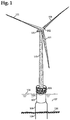
- Fig. 1 depicts generally an individual wind turbine out of the many that would compose a wind farm.
- the offshore wind turbine components include the turbine which consists of the nacelle 100, the rotor with the blades 101, and the hub 102.
- the rotor is connected through a drive train to the generator which is housed in the nacelle.
- Various sensors and control actuators such as for pitch and yaw controls (not shown) may be included in the nacelle and hub.
- the nacelle, blades and hub are mounted at the top of the tower 103, which incorporates a platform 104, connected to a transition piece 105.
- the platform is disposed sufficiently above the sea surface 106, but part of the transition piece 105 is typically below the sea surface and in the water 107.
- the transition piece connects to the foundation structure, a type of which is the monopile 108 illustrated in the figure.
- a sufficient in length segment of the monopile 109 is embedded into the sea bed 110 to provide a secure foundation.
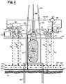
- the power generated by the turbine is transmitted by cable 200, to the turbine transformer or power control unit 201.
- the turbine power control unit typically steps up the voltage of the generated power and connects it to the inner-array electric power cable 202, which enters and exits the foundation near the mud line.
- the turbine power control unit functions also include appropriate power supply 203 to the compressor; appropriate power supply to local pump/flow controls 204 in that turbine's branch cooling circuit 205 and branch heating circuit 206; appropriate power supply 207, if necessary, to the reheaters 212b, and reception and conditioning of generated-from-storage power 208.
- the local pump/flow controls are needed to circulate cool fluid from the cooling circuit through the compressor after cooler, if any (not shown) and the intercoolers 211, and regulate the flows; and to circulate hot fluid from the heating circuit through any preheater 212 and reheaters 212b, and regulate the flows.
- the cooled fluid exiting any preheater 212 and reheaters 211b enter the cooling circuit 209, while the heated fluid exiting the intercoolers 211 enter the heating circuit 210.
- the power circuits may include additional sub-control units such as 213.
- the branch thermal circuits may also include necessary additional flow controls such as check valves, et cetera, illustrated generally in Fig. 2 by the devices 214.
- Fig. 2 also illustrates generally the distributed or local system control system 215, the compressor train 216, and the expander/generator train 217. All these units 215-217, flow devices 204, 214, power controls 201,213, and associated structures and accessories are contained on a platform 104 which may be the same or separate from the general work platform 104 indicated in Fig. 1 .
- Compressed air 218 leaving the compressor train 216 enter the air storage tank 219 through a complement of flow and pressure control devices 220.
- Compressed air supply 221 to the expander/generator train 217 exit the air storage 219 through a complement of flow and pressure control devices 222.
- Fig. 2 also shows the air storage tank 219 fully contained in the transition piece 105.
- the air storage may be contained in one or more of the support elements, that is, the monopile or foundation piece 109, the transition piece 105 and the tower 103.
- the support elements that is, the monopile or foundation piece 109, the transition piece 105 and the tower 103.
- roughly 2500 m 3 of storage volume may be needed to produce 20 MWh of energy, assuming adiabatic compression. This volume can be accommodated within approximately 60 m length of a 7.3 m internal diameter cylindrical storage vessel (excluding internal structural elements).
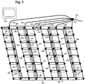
- FIG. 3 an illustrative distribution of wind turbine units 300 is shown. It is understood that offshore wind farm layouts vary in pattern and number of turbine units constituting the farm.
- the turbine units are linked in strings by inner-array cables 202, previously described.
- the strings link to the farm substation or switch yard 301 via the outer-array cables 302, and power leaves the wind farm or connects to the onshore transmission system via the export cable 303.
- the farm power cables are buried or covered on the sea floor.
- the thermal energy interchange network of cooling circuits 209 and heating circuits 210 may also be deployed on the sea floor, so that certain physical attributes and installation of the heat interchange network may be akin to the layout and deployment of the power cable network.
- the thermal energy networks illustrated in Fig. 3 incorporate circuit headers 304 and 305, which respectively, distribute the cool and hot fluids to the cooling and heating circuits, 209 and 210.
- the flow through the cooling and heating headers and pressure and thermal mixing in the cooling and heating circuits are maintained by pumping stations and associated flow and pressure control devices, illustrated generally in Fig. 3 by pumps 306 and 307 respectively.
- Fig. 3 also illustrates generally, the central or supervisory control systems for the wind farm and distributed compressed air energy storage with heat networks system 308.
- the thermal energy network drives 306 and 307 are centrally powered 309, and centrally controlled in the control systems 308.
- the thermal circuits are closed loops, with possible occasional make-up of fluid 310, in the cool fluid loop.
- the circulating fluids could be sea water, given the environment of the offshore wind intermittent power resource embodied in this description, however such application is not to be considered in any way limiting to this invention.
- the thermal energy interchange network of cooling circuits 209 and heating circuits 210 may be composed of uninsulated and insulated undersea flow pipes and accessories, utilizing established technology for offshore oil/gas production subsea substations and pipeline systems.
- the wind farm management and operation control system requires significant changes from conventional wind farm control systems. Ordinarily, this is a hierarchical system of a farm level controller 308, and turbine level controller 215.
- the turbine level control could be in three levels: turbine supervisory control, operational control and subsystem control, which ensure various actuators, yaw drive, pitch drives, the generator, and the power electronics realize and maintain their set points.
- the typical objective of the farm level controller is control of the farm generated power which may need to track some external power demand; and coordinated control of the power production by individual farm turbines to mitigate variations in wind flow conditions at turbine sites and aerodynamic interactions of the turbines.
- turbine supervisory controller typically determines when the turbine is started or stopped and conducts turbine health monitoring tasks, while the turbine operational controller regulates turbine operation in meetings 2 and 3.
- the turbine subsystem controls multiply to include the additional components associated with the compressor and expander/generator trains and the air storage tank; the farm level controller objectives expand to include regulation of flow and energy interchange in the heat network and optimization of thermal efficiency throughout the farm.
- the "operation" regimes of each turbine station (this includes when turbine is not run or when turbine is shut down) become elaborated, with each regime incorporating combinations of (a) turbine "operation” without compressed air energy storage and compressed air power production, (b) turbine “operation” with compressed air energy storage, and (c) turbine “operation” with compressed air power production.
- the turbine supervisory controller functions and objectives are accordingly elaborated.
Landscapes
- Engineering & Computer Science (AREA)
- Life Sciences & Earth Sciences (AREA)
- Sustainable Development (AREA)
- Sustainable Energy (AREA)
- Chemical & Material Sciences (AREA)
- Combustion & Propulsion (AREA)
- Mechanical Engineering (AREA)
- General Engineering & Computer Science (AREA)
- Power Engineering (AREA)
- Wind Motors (AREA)
Claims (9)
- Dispositif pour l'utilisation d'une mémoire de l'énergie obtenue de l'air comprimé pour l'amélioration du facteur de capacité des turbines éoliennes d'un parc éolien caractérisé par les étapes qui suivent:- Une mémoire d'air (219) est répartie,- Une compression et une expansion d'une variété de réservoirs de stockage (219) et de trains compresseurs-extenseurs (216, 217) sont prévus au sein de chaque turbine éolienne,- Un réseau d'énergie thermique-échangeur de la chaleur est prévu reliant toutes les turbines éoliennes par le biais de circuits isolés et commandés (209, 210) pour le refroidissement et le chauffage,- Des contrôleurs de surveillance du niveau du parc et des contrôleurs répartis du niveau des turbines (215) sont utilisés procédant à titre dynamique à une génération de puissance individuelle des turbines et/ou à un stockage de l'énergie de l'ai comprimé ou à une génération de puissance de l'air comprimé en relation avec les possibilités de fonctionnement et à l'optimisation du grade de l'effet thermique et au facteur de capacité pour le parc éolien.
- Dispositif selon la revendication 1 est caractérisé de sorte que les turbines éoliennes, la mémoire d'air répartie (219), les systèmes de compression et d'expansion, le réseau d'énergie thermique-échangeur de la chaleur et les systèmes de commande sont formés en ce qui concerne l'intégration et le fonctionnement en qualité de système pour l'appel à la génération de puissance en efficacité optimale thermique où- la performance des turbines éoliennes pour la performance du parc y inclus pour l'accomplissement de la demande à la performance, la compression de l'air et le fonctionnement des contrôleurs de refroidissement et de chauffage (209, 210) est produite,- et où la performance produite est utilisable grâce à l'air comprimé pour la performance du parc où la chaleur produite lors de la compression de l'air est intégrée dans le réseau d'énergie thermique-échangeur de la chaleur.
- Dispositif selon la revendication 1 est caractérisé de sorte qu'un système de commande hiérarchique est prévu procédant dans les contrôleurs du niveau du parc à un réglage du flux du liquide et à un échange d'énergie au niveau du réseau de la chaleur ainsi qu'à une optimisation de l'efficacité thermique dans le parc éolien,
Que des réglages de fonctionnement sont formés à travers les contrôleurs de niveau des turbines servant à entourer les combinaisons (1) de l'opération des turbines éoliennes ne contenant pas la course, la course lors de la vitesse du vent via une vitesse cut-in et sous une vitesse autorisée du vent pour une haute vitesse du rotor et la course pendant les vitesses via une vitesse autorisée du vent pour une haute vitesse du rotor, mais sous une vitesse du vent Roll,
Et que (1) la fermeture de la turbine pour des raisons de sécurité (2), une mémoire de l'énergie de l'air comprimé et (3) une génération de puissance de l'air comprimé sont prévues. - Système pour le stockage de l'énergie de l'air comprimé pour l'amélioration du facteur de capacité des turbines éoliennes réparties d'un parc éolien avec- un parc éolien présentant des turbines éoliennes,- Une mémoire d'air répartie (219) présentant une variété de réservoirs de stockage (219) et des trains de compression et d'expansion (216,217) qui sont compressibles et expansibles à chaque turbine éolienne,- Un réseau d'énergie thermique-échangeur de la chaleur reliant toutes les turbines éoliennes par le biais de contrôleurs isolés et commandés de refroidissement et de chauffage (209,210),- Et des contrôleurs de surveillance du niveau du parc et des contrôleurs répartis du niveau des turbines (215) qui sont incorporés pour planifier à titre dynamique la génération de la puissance individuelle des turbines et/ou le stockage d'énergie de l'air comprimé ou la génération de la puissance de l'air comprimé en relation avec les possibilités de fonctionnement du parc éolien et une optimisation de l'efficacité thermique et du facteur de capacité du parc éolien.
- Système selon la revendication 4 est caractérisé de sorte que les turbines éoliennes, la mémoire d'air répartie (219), les systèmes de compression et d'expansion, le réseau d'énergie thermique-échangeur de la chaleur et l'un des systèmes de commande sont intégrés et sont formés en qualité de système à l'appel pour la génération de puissance en cas d'efficacité thermique optimal où- La performance produite par les turbines éoliennes utilisables pour la performance du parc, la demande à l'accomplissement de la performance, la compression de l'air et le fonctionnement des contrôleurs pour le refroidissement et le chauffage (209,210), y inclus et- que la performance produite par l'air comprimé est utilisée pour la performance du parc et où la chaleur produite lors de la compression de l'air est intégrée dans le réseau d'énergie thermique-échangeur de la chaleur et que l'appel à la chaleur est perçue lors de l'expansion de l'air à travers le réseau d'énergie thermique-échangeur de la chaleur.
- Système selon la revendication 4 est caractérisé de sorte qu'un système de commande hiérarchique est prévu prévoyant un réglage dans les contrôleurs du niveau du parc du flux du liquide et un échange d'énergie au niveau du réseau du chauffage ainsi qu'une optimisation de l'efficacité thermique dans le parc éolien,
Que les réglages de l'opération effectués à travers les contrôleurs du niveau des turbines sont formés de telle sorte qu'ils contiennent des combinaisons (1) d'une opération de turbines éoliennes non pas de la course, de la course pendant la vitesse du vent via une vitesse cut-in et sous une vitesse autorisée du vent pour une haute vitesse du rotor et la course pendant les vitesses via une vitesse autorisée de vent pour une haute vitesse du rotor, mais sous une vitesse Roll du vent,
Et que (1) la fermeture des turbines pour des raisons de sécurité, (2) un stockage de l'énergie de l'air comprimé et (3) une génération de puissance de l'air comprimé sont prévues. - Système selon la revendication 5 est caractérisé de sorte que la mémoire de l'air, la compression et l'expansion se réfèrent au réservoir de stockage de l'air (219), le train compresseur (217) et le train générateur expansible (216) et à leurs accessoires présentent des refroidisseurs, des refroidisseurs intermédiaires, des préchauffeurs et des réchauffeurs, des dispositifs d'écoulement, des dispositifs électroniques de puissance qui sont intégrés ou encore non dans des tours de turbines (103) et que des structures de support sont prévues comme à titre d'exemple une plateforme (104), un raccord de réduction et un raccord de fondement.
- Système selon la revendication 5 est caractérisé de sorte que le réseau d'énergie thermique-échangeur de la chaleur se compose de conduits non isolés et isolés au fond marin qui sont stockés là bas ou sont portés par le fond marin et qui relient non seulement les refroidisseurs intermédiaires du compresseur de l'air comprimé et les post-refroidisseurs mais aussi les préchauffeurs expansibles de l'air comprimé et les réchauffeurs pour former des contrôleurs de chauffage et de refroidissement (209,210) avec les en-têtes nécessaires, les stations de pompage et les dispositifs de commande de la pression.
- Système selon la revendication 5 est caractérisé de sorte que les turbines éoliennes sont reliées par le biais d'un réseau de câbles d'alimentation en courant électrique disposés à l'intérieur (202) qui sont stockés là bas ou sont portés par le fond marin reliant là bas chaque turbine éolienne par une unité de commande en alimentation en courant,
Et qu'un ensemble de câbles disposés à l'extérieur (302), une sous-station du parc éolien ou un point de commutation ainsi que des dispositifs de commande et des dispositifs complémentaires sont prévus qui collectent et transfèrent la puissance produite par le parc éolien.
Applications Claiming Priority (1)
| Application Number | Priority Date | Filing Date | Title |
|---|---|---|---|
| PCT/US2016/026841 WO2016134385A2 (fr) | 2015-02-16 | 2016-04-09 | Stockage d'énergie par air comprimé réparti avec réseau thermique |
Publications (3)
| Publication Number | Publication Date |
|---|---|
| EP3259473A2 EP3259473A2 (fr) | 2017-12-27 |
| EP3259473A4 EP3259473A4 (fr) | 2018-06-20 |
| EP3259473B1 true EP3259473B1 (fr) | 2020-07-08 |
Family
ID=60955414
Family Applications (1)
| Application Number | Title | Priority Date | Filing Date |
|---|---|---|---|
| EP16753239.9A Active EP3259473B1 (fr) | 2016-04-09 | 2016-04-09 | Parc éolien avec stockage d'énergie par air comprimé |
Country Status (1)
| Country | Link |
|---|---|
| EP (1) | EP3259473B1 (fr) |
Families Citing this family (10)
| Publication number | Priority date | Publication date | Assignee | Title |
|---|---|---|---|---|
| CN109583012B (zh) * | 2018-10-18 | 2023-03-24 | 国网安徽省电力有限公司 | 先进绝热压缩空气储能与风电协同运行调度方法与装置 |
| EP4196671A1 (fr) * | 2020-08-12 | 2023-06-21 | Mehmet Kurt | Appareil en boucle fermée pour génération d'énergie électrique |
| CN112283069B (zh) * | 2020-10-28 | 2022-08-16 | 西安热工研究院有限公司 | 一种基于非补燃式压缩空气储能的光储结合电站 |
| CN113175415A (zh) * | 2021-04-16 | 2021-07-27 | 西安热工研究院有限公司 | 一种海上风电耦合等温压缩膨胀空气储能系统及方法 |
| CN114386684A (zh) * | 2021-12-29 | 2022-04-22 | 贵州电网有限责任公司 | 一种膨胀发电系统储气罐出力预测方法 |
| CN116031899A (zh) * | 2023-01-09 | 2023-04-28 | 中国长江三峡集团有限公司 | 绝热压缩空气储能辅助风电场调频的方法及相关组件 |
| CN116085200A (zh) * | 2023-01-18 | 2023-05-09 | 中国船舶集团风电发展有限公司 | 一种用于海上风力发电的单桩储能装置 |
| CN116816648B (zh) * | 2023-04-07 | 2025-01-17 | 中国长江三峡集团有限公司 | 压缩空气联储共热系统、电力系统及压缩空气储能方法 |
| CN116412103B (zh) * | 2023-04-07 | 2025-01-17 | 中国长江三峡集团有限公司 | 紧凑式压缩空气储能系统、电力系统及压缩空气储能方法 |
| CN117662416B (zh) * | 2023-10-18 | 2025-01-17 | 中国长江三峡集团有限公司 | 多级压缩空气储能系统及发电站 |
Family Cites Families (2)
| Publication number | Priority date | Publication date | Assignee | Title |
|---|---|---|---|---|
| WO2003031813A1 (fr) * | 2001-10-05 | 2003-04-17 | Ben Enis | Procede et dispositif permettant d'utiliser des eoliennes pour la production et la fourniture ininterrompue d'energie a des points de livraison eloignes du reseau de distribution generale |
| EP2952736A3 (fr) * | 2014-05-15 | 2016-02-24 | Charles Martin Chavez Madson | Éolienne, agencement d'une pluralité d'éoliennes, réservoir de réserve permettant de stocker de l'air comprimé et éolienne et système de stockage d'air comprimé pour la production d'énergie électrique |
-
2016
- 2016-04-09 EP EP16753239.9A patent/EP3259473B1/fr active Active
Non-Patent Citations (1)
| Title |
|---|
| None * |
Also Published As
| Publication number | Publication date |
|---|---|
| EP3259473A2 (fr) | 2017-12-27 |
| EP3259473A4 (fr) | 2018-06-20 |
Similar Documents
| Publication | Publication Date | Title |
|---|---|---|
| EP3259473B1 (fr) | Parc éolien avec stockage d'énergie par air comprimé | |
| US20180238304A1 (en) | Distributed compressed air energy storage with heat network | |
| US12088096B2 (en) | Integrated power production and storage systems | |
| US7974742B2 (en) | Method of coordinating and stabilizing the delivery of wind generated energy | |
| US7308361B2 (en) | Method of coordinating and stabilizing the delivery of wind generated energy | |
| Tola et al. | Performance assessment of Adiabatic Compressed Air Energy Storage (A-CAES) power plants integrated with packed-bed thermocline storage systems | |
| US6963802B2 (en) | Method of coordinating and stabilizing the delivery of wind generated energy | |
| Luo et al. | Overview of current development in compressed air energy storage technology | |
| US7325401B1 (en) | Power conversion systems | |
| US5845479A (en) | Method for providing emergency reserve power using storage techniques for electrical systems applications | |
| CN107534315A (zh) | 压缩空气储能发电方法及压缩空气储能发电装置 | |
| Daneshi et al. | Generation scheduling with integration of wind power and compressed air energy storage | |
| Edrisian et al. | The new hybrid model of compressed air for stable production of wind farms | |
| Enis et al. | Operation of hybrid wind-turbine compressed-air system for connection to electric grid networks and cogeneration | |
| AU2004250158B2 (en) | A method of coordinating and stabilizing the delivery of wind generated energy | |
| EP4350142A1 (fr) | Système d'alimentation auxiliaire et commande pour éoliennes rurales et/ou hors réseau | |
| US11952922B2 (en) | Operation of a thermal energy storage system | |
| US20260125812A1 (en) | Integrated power production and storage systems | |
| US20260063106A1 (en) | Tide- and wind-powered turbine, conversion and storage system | |
| Stavropoulos et al. | Subsea electrical power generation for localised subsea applications | |
| Riaz | Feasibility of compressed air energy storage to store wind energy on daily and monthly basis | |
| WO2023102250A1 (fr) | Système de pipeline et procédé de stockage et de distribution d'énergie à air comprimé | |
| PATIL | Various Energy Storage Devices and Their Control Techniques | |
| Kramer | Optimized combined heat and power energy applications and renewables |
Legal Events
| Date | Code | Title | Description |
|---|---|---|---|
| STAA | Information on the status of an ep patent application or granted ep patent |
Free format text: STATUS: THE INTERNATIONAL PUBLICATION HAS BEEN MADE |
|
| PUAI | Public reference made under article 153(3) epc to a published international application that has entered the european phase |
Free format text: ORIGINAL CODE: 0009012 |
|
| STAA | Information on the status of an ep patent application or granted ep patent |
Free format text: STATUS: REQUEST FOR EXAMINATION WAS MADE |
|
| 17P | Request for examination filed |
Effective date: 20170918 |
|
| AK | Designated contracting states |
Kind code of ref document: A2 Designated state(s): AL AT BE BG CH CY CZ DE DK EE ES FI FR GB GR HR HU IE IS IT LI LT LU LV MC MK MT NL NO PL PT RO RS SE SI SK SM TR |
|
| AX | Request for extension of the european patent |
Extension state: BA ME |
|
| REG | Reference to a national code |
Ref country code: DE Ref legal event code: R079 Ref document number: 602016039556 Country of ref document: DE Free format text: PREVIOUS MAIN CLASS: F03D0007040000 Ipc: F03D0009170000 |
|
| A4 | Supplementary search report drawn up and despatched |
Effective date: 20180522 |
|
| RIC1 | Information provided on ipc code assigned before grant |
Ipc: F03D 13/25 20160101ALI20180515BHEP Ipc: F03D 9/25 20160101ALI20180515BHEP Ipc: F03D 7/04 20060101ALI20180515BHEP Ipc: F03D 9/17 20160101AFI20180515BHEP |
|
| DAV | Request for validation of the european patent (deleted) | ||
| DAX | Request for extension of the european patent (deleted) | ||
| GRAP | Despatch of communication of intention to grant a patent |
Free format text: ORIGINAL CODE: EPIDOSNIGR1 |
|
| STAA | Information on the status of an ep patent application or granted ep patent |
Free format text: STATUS: GRANT OF PATENT IS INTENDED |
|
| GRAJ | Information related to disapproval of communication of intention to grant by the applicant or resumption of examination proceedings by the epo deleted |
Free format text: ORIGINAL CODE: EPIDOSDIGR1 |
|
| STAA | Information on the status of an ep patent application or granted ep patent |
Free format text: STATUS: REQUEST FOR EXAMINATION WAS MADE |
|
| INTG | Intention to grant announced |
Effective date: 20200129 |
|
| GRAP | Despatch of communication of intention to grant a patent |
Free format text: ORIGINAL CODE: EPIDOSNIGR1 |
|
| STAA | Information on the status of an ep patent application or granted ep patent |
Free format text: STATUS: GRANT OF PATENT IS INTENDED |
|
| INTC | Intention to grant announced (deleted) | ||
| INTG | Intention to grant announced |
Effective date: 20200312 |
|
| GRAS | Grant fee paid |
Free format text: ORIGINAL CODE: EPIDOSNIGR3 |
|
| GRAA | (expected) grant |
Free format text: ORIGINAL CODE: 0009210 |
|
| STAA | Information on the status of an ep patent application or granted ep patent |
Free format text: STATUS: THE PATENT HAS BEEN GRANTED |
|
| AK | Designated contracting states |
Kind code of ref document: B1 Designated state(s): AL AT BE BG CH CY CZ DE DK EE ES FI FR GB GR HR HU IE IS IT LI LT LU LV MC MK MT NL NO PL PT RO RS SE SI SK SM TR |
|
| REG | Reference to a national code |
Ref country code: CH Ref legal event code: EP Ref country code: AT Ref legal event code: REF Ref document number: 1288744 Country of ref document: AT Kind code of ref document: T Effective date: 20200715 |
|
| REG | Reference to a national code |
Ref country code: DE Ref legal event code: R096 Ref document number: 602016039556 Country of ref document: DE |
|
| REG | Reference to a national code |
Ref country code: IE Ref legal event code: FG4D |
|
| REG | Reference to a national code |
Ref country code: DK Ref legal event code: T3 Effective date: 20201009 |
|
| REG | Reference to a national code |
Ref country code: NL Ref legal event code: FP |
|
| REG | Reference to a national code |
Ref country code: LT Ref legal event code: MG4D |
|
| REG | Reference to a national code |
Ref country code: AT Ref legal event code: MK05 Ref document number: 1288744 Country of ref document: AT Kind code of ref document: T Effective date: 20200708 |
|
| PG25 | Lapsed in a contracting state [announced via postgrant information from national office to epo] |
Ref country code: FI Free format text: LAPSE BECAUSE OF FAILURE TO SUBMIT A TRANSLATION OF THE DESCRIPTION OR TO PAY THE FEE WITHIN THE PRESCRIBED TIME-LIMIT Effective date: 20200708 Ref country code: LT Free format text: LAPSE BECAUSE OF FAILURE TO SUBMIT A TRANSLATION OF THE DESCRIPTION OR TO PAY THE FEE WITHIN THE PRESCRIBED TIME-LIMIT Effective date: 20200708 Ref country code: HR Free format text: LAPSE BECAUSE OF FAILURE TO SUBMIT A TRANSLATION OF THE DESCRIPTION OR TO PAY THE FEE WITHIN THE PRESCRIBED TIME-LIMIT Effective date: 20200708 Ref country code: SE Free format text: LAPSE BECAUSE OF FAILURE TO SUBMIT A TRANSLATION OF THE DESCRIPTION OR TO PAY THE FEE WITHIN THE PRESCRIBED TIME-LIMIT Effective date: 20200708 Ref country code: NO Free format text: LAPSE BECAUSE OF FAILURE TO SUBMIT A TRANSLATION OF THE DESCRIPTION OR TO PAY THE FEE WITHIN THE PRESCRIBED TIME-LIMIT Effective date: 20201008 Ref country code: GR Free format text: LAPSE BECAUSE OF FAILURE TO SUBMIT A TRANSLATION OF THE DESCRIPTION OR TO PAY THE FEE WITHIN THE PRESCRIBED TIME-LIMIT Effective date: 20201009 Ref country code: AT Free format text: LAPSE BECAUSE OF FAILURE TO SUBMIT A TRANSLATION OF THE DESCRIPTION OR TO PAY THE FEE WITHIN THE PRESCRIBED TIME-LIMIT Effective date: 20200708 Ref country code: BG Free format text: LAPSE BECAUSE OF FAILURE TO SUBMIT A TRANSLATION OF THE DESCRIPTION OR TO PAY THE FEE WITHIN THE PRESCRIBED TIME-LIMIT Effective date: 20201008 Ref country code: PT Free format text: LAPSE BECAUSE OF FAILURE TO SUBMIT A TRANSLATION OF THE DESCRIPTION OR TO PAY THE FEE WITHIN THE PRESCRIBED TIME-LIMIT Effective date: 20201109 |
|
| PG25 | Lapsed in a contracting state [announced via postgrant information from national office to epo] |
Ref country code: RS Free format text: LAPSE BECAUSE OF FAILURE TO SUBMIT A TRANSLATION OF THE DESCRIPTION OR TO PAY THE FEE WITHIN THE PRESCRIBED TIME-LIMIT Effective date: 20200708 Ref country code: PL Free format text: LAPSE BECAUSE OF FAILURE TO SUBMIT A TRANSLATION OF THE DESCRIPTION OR TO PAY THE FEE WITHIN THE PRESCRIBED TIME-LIMIT Effective date: 20200708 Ref country code: LV Free format text: LAPSE BECAUSE OF FAILURE TO SUBMIT A TRANSLATION OF THE DESCRIPTION OR TO PAY THE FEE WITHIN THE PRESCRIBED TIME-LIMIT Effective date: 20200708 Ref country code: IS Free format text: LAPSE BECAUSE OF FAILURE TO SUBMIT A TRANSLATION OF THE DESCRIPTION OR TO PAY THE FEE WITHIN THE PRESCRIBED TIME-LIMIT Effective date: 20201108 |
|
| REG | Reference to a national code |
Ref country code: ES Ref legal event code: FG2A Ref document number: 2818181 Country of ref document: ES Kind code of ref document: T3 Effective date: 20210409 Ref country code: DE Ref legal event code: R097 Ref document number: 602016039556 Country of ref document: DE |
|
| PG25 | Lapsed in a contracting state [announced via postgrant information from national office to epo] |
Ref country code: EE Free format text: LAPSE BECAUSE OF FAILURE TO SUBMIT A TRANSLATION OF THE DESCRIPTION OR TO PAY THE FEE WITHIN THE PRESCRIBED TIME-LIMIT Effective date: 20200708 Ref country code: SM Free format text: LAPSE BECAUSE OF FAILURE TO SUBMIT A TRANSLATION OF THE DESCRIPTION OR TO PAY THE FEE WITHIN THE PRESCRIBED TIME-LIMIT Effective date: 20200708 Ref country code: RO Free format text: LAPSE BECAUSE OF FAILURE TO SUBMIT A TRANSLATION OF THE DESCRIPTION OR TO PAY THE FEE WITHIN THE PRESCRIBED TIME-LIMIT Effective date: 20200708 Ref country code: CZ Free format text: LAPSE BECAUSE OF FAILURE TO SUBMIT A TRANSLATION OF THE DESCRIPTION OR TO PAY THE FEE WITHIN THE PRESCRIBED TIME-LIMIT Effective date: 20200708 |
|
| PLBE | No opposition filed within time limit |
Free format text: ORIGINAL CODE: 0009261 |
|
| STAA | Information on the status of an ep patent application or granted ep patent |
Free format text: STATUS: NO OPPOSITION FILED WITHIN TIME LIMIT |
|
| PG25 | Lapsed in a contracting state [announced via postgrant information from national office to epo] |
Ref country code: AL Free format text: LAPSE BECAUSE OF FAILURE TO SUBMIT A TRANSLATION OF THE DESCRIPTION OR TO PAY THE FEE WITHIN THE PRESCRIBED TIME-LIMIT Effective date: 20200708 |
|
| 26N | No opposition filed |
Effective date: 20210409 |
|
| PG25 | Lapsed in a contracting state [announced via postgrant information from national office to epo] |
Ref country code: SK Free format text: LAPSE BECAUSE OF FAILURE TO SUBMIT A TRANSLATION OF THE DESCRIPTION OR TO PAY THE FEE WITHIN THE PRESCRIBED TIME-LIMIT Effective date: 20200708 |
|
| PG25 | Lapsed in a contracting state [announced via postgrant information from national office to epo] |
Ref country code: SI Free format text: LAPSE BECAUSE OF FAILURE TO SUBMIT A TRANSLATION OF THE DESCRIPTION OR TO PAY THE FEE WITHIN THE PRESCRIBED TIME-LIMIT Effective date: 20200708 |
|
| PG25 | Lapsed in a contracting state [announced via postgrant information from national office to epo] |
Ref country code: MC Free format text: LAPSE BECAUSE OF FAILURE TO SUBMIT A TRANSLATION OF THE DESCRIPTION OR TO PAY THE FEE WITHIN THE PRESCRIBED TIME-LIMIT Effective date: 20200708 |
|
| PG25 | Lapsed in a contracting state [announced via postgrant information from national office to epo] |
Ref country code: LU Free format text: LAPSE BECAUSE OF NON-PAYMENT OF DUE FEES Effective date: 20210409 |
|
| PG25 | Lapsed in a contracting state [announced via postgrant information from national office to epo] |
Ref country code: LI Free format text: LAPSE BECAUSE OF NON-PAYMENT OF DUE FEES Effective date: 20210430 Ref country code: CH Free format text: LAPSE BECAUSE OF NON-PAYMENT OF DUE FEES Effective date: 20210430 |
|
| PG25 | Lapsed in a contracting state [announced via postgrant information from national office to epo] |
Ref country code: IE Free format text: LAPSE BECAUSE OF NON-PAYMENT OF DUE FEES Effective date: 20210409 |
|
| PG25 | Lapsed in a contracting state [announced via postgrant information from national office to epo] |
Ref country code: IS Free format text: LAPSE BECAUSE OF FAILURE TO SUBMIT A TRANSLATION OF THE DESCRIPTION OR TO PAY THE FEE WITHIN THE PRESCRIBED TIME-LIMIT Effective date: 20201108 |
|
| PG25 | Lapsed in a contracting state [announced via postgrant information from national office to epo] |
Ref country code: HU Free format text: LAPSE BECAUSE OF FAILURE TO SUBMIT A TRANSLATION OF THE DESCRIPTION OR TO PAY THE FEE WITHIN THE PRESCRIBED TIME-LIMIT; INVALID AB INITIO Effective date: 20160409 |
|
| PG25 | Lapsed in a contracting state [announced via postgrant information from national office to epo] |
Ref country code: CY Free format text: LAPSE BECAUSE OF FAILURE TO SUBMIT A TRANSLATION OF THE DESCRIPTION OR TO PAY THE FEE WITHIN THE PRESCRIBED TIME-LIMIT Effective date: 20200708 |
|
| PG25 | Lapsed in a contracting state [announced via postgrant information from national office to epo] |
Ref country code: MK Free format text: LAPSE BECAUSE OF FAILURE TO SUBMIT A TRANSLATION OF THE DESCRIPTION OR TO PAY THE FEE WITHIN THE PRESCRIBED TIME-LIMIT Effective date: 20200708 |
|
| PG25 | Lapsed in a contracting state [announced via postgrant information from national office to epo] |
Ref country code: TR Free format text: LAPSE BECAUSE OF FAILURE TO SUBMIT A TRANSLATION OF THE DESCRIPTION OR TO PAY THE FEE WITHIN THE PRESCRIBED TIME-LIMIT Effective date: 20200708 |
|
| PG25 | Lapsed in a contracting state [announced via postgrant information from national office to epo] |
Ref country code: MT Free format text: LAPSE BECAUSE OF FAILURE TO SUBMIT A TRANSLATION OF THE DESCRIPTION OR TO PAY THE FEE WITHIN THE PRESCRIBED TIME-LIMIT Effective date: 20200708 |
|
| PGFP | Annual fee paid to national office [announced via postgrant information from national office to epo] |
Ref country code: NL Payment date: 20250418 Year of fee payment: 10 |
|
| PGFP | Annual fee paid to national office [announced via postgrant information from national office to epo] |
Ref country code: DE Payment date: 20250422 Year of fee payment: 10 |
|
| PGFP | Annual fee paid to national office [announced via postgrant information from national office to epo] |
Ref country code: GB Payment date: 20250423 Year of fee payment: 10 Ref country code: ES Payment date: 20250529 Year of fee payment: 10 Ref country code: DK Payment date: 20250429 Year of fee payment: 10 |
|
| PGFP | Annual fee paid to national office [announced via postgrant information from national office to epo] |
Ref country code: BE Payment date: 20250418 Year of fee payment: 10 Ref country code: IT Payment date: 20250424 Year of fee payment: 10 |
|
| PGFP | Annual fee paid to national office [announced via postgrant information from national office to epo] |
Ref country code: FR Payment date: 20250425 Year of fee payment: 10 |