EP3259841B1 - Erkennung von umkehrpolarität bei in reihe geschalteten fotovoltaikmodulen - Google Patents
Erkennung von umkehrpolarität bei in reihe geschalteten fotovoltaikmodulen Download PDFInfo
- Publication number
- EP3259841B1 EP3259841B1 EP16706774.3A EP16706774A EP3259841B1 EP 3259841 B1 EP3259841 B1 EP 3259841B1 EP 16706774 A EP16706774 A EP 16706774A EP 3259841 B1 EP3259841 B1 EP 3259841B1
- Authority
- EP
- European Patent Office
- Prior art keywords
- fuse
- fuse holder
- photovoltaic
- reverse polarity
- holder body
- Prior art date
- Legal status (The legal status is an assumption and is not a legal conclusion. Google has not performed a legal analysis and makes no representation as to the accuracy of the status listed.)
- Not-in-force
Links
- 238000001514 detection method Methods 0.000 title claims description 44
- 238000009434 installation Methods 0.000 claims description 25
- 238000000034 method Methods 0.000 claims description 4
- 238000002955 isolation Methods 0.000 claims description 3
- 238000010586 diagram Methods 0.000 description 11
- 230000004397 blinking Effects 0.000 description 2
- 238000003780 insertion Methods 0.000 description 2
- 230000037431 insertion Effects 0.000 description 2
- 230000001419 dependent effect Effects 0.000 description 1
- 230000005611 electricity Effects 0.000 description 1
- 230000006870 function Effects 0.000 description 1
- 238000010248 power generation Methods 0.000 description 1
- 230000002123 temporal effect Effects 0.000 description 1
Images




Classifications
-
- H—ELECTRICITY
- H02—GENERATION; CONVERSION OR DISTRIBUTION OF ELECTRIC POWER
- H02H—EMERGENCY PROTECTIVE CIRCUIT ARRANGEMENTS
- H02H11/00—Emergency protective circuit arrangements for preventing the switching-on in case an undesired electric working condition might result
- H02H11/002—Emergency protective circuit arrangements for preventing the switching-on in case an undesired electric working condition might result in case of inverted polarity or connection; with switching for obtaining correct connection
-
- H—ELECTRICITY
- H02—GENERATION; CONVERSION OR DISTRIBUTION OF ELECTRIC POWER
- H02S—GENERATION OF ELECTRIC POWER BY CONVERSION OF INFRARED RADIATION, VISIBLE LIGHT OR ULTRAVIOLET LIGHT, e.g. USING PHOTOVOLTAIC [PV] MODULES
- H02S50/00—Monitoring or testing of PV systems, e.g. load balancing or fault identification
-
- H—ELECTRICITY
- H01—ELECTRIC ELEMENTS
- H01H—ELECTRIC SWITCHES; RELAYS; SELECTORS; EMERGENCY PROTECTIVE DEVICES
- H01H85/00—Protective devices in which the current flows through a part of fusible material and this current is interrupted by displacement of the fusible material when this current becomes excessive
- H01H85/02—Details
- H01H85/04—Fuses, i.e. expendable parts of the protective device, e.g. cartridges
- H01H85/05—Component parts thereof
-
- H—ELECTRICITY
- H02—GENERATION; CONVERSION OR DISTRIBUTION OF ELECTRIC POWER
- H02S—GENERATION OF ELECTRIC POWER BY CONVERSION OF INFRARED RADIATION, VISIBLE LIGHT OR ULTRAVIOLET LIGHT, e.g. USING PHOTOVOLTAIC [PV] MODULES
- H02S99/00—Subject matter not provided for in other groups of this subclass
-
- Y—GENERAL TAGGING OF NEW TECHNOLOGICAL DEVELOPMENTS; GENERAL TAGGING OF CROSS-SECTIONAL TECHNOLOGIES SPANNING OVER SEVERAL SECTIONS OF THE IPC; TECHNICAL SUBJECTS COVERED BY FORMER USPC CROSS-REFERENCE ART COLLECTIONS [XRACs] AND DIGESTS
- Y02—TECHNOLOGIES OR APPLICATIONS FOR MITIGATION OR ADAPTATION AGAINST CLIMATE CHANGE
- Y02E—REDUCTION OF GREENHOUSE GAS [GHG] EMISSIONS, RELATED TO ENERGY GENERATION, TRANSMISSION OR DISTRIBUTION
- Y02E10/00—Energy generation through renewable energy sources
- Y02E10/50—Photovoltaic [PV] energy
Definitions
- photovoltaic arrangements such as photovoltaic systems comprising solar panels that absorb and convert sunlight into electricity for power generation.
- An inverter may be configured to convert DC power from a photovoltaic arrangement to AC power for an AC power grid that may supply power to destination such as a building.
- the photovoltaic arrangement may comprise a plurality of photovoltaic strings that may be combined in parallel by a photovoltaic string combiner.
- a photovoltaic string may comprise a plurality of photovoltaic panels that are connected in series, which may produce an output voltage that is a summation of voltages of the respective photovoltaic panels.
- a photovoltaic string is installed incorrectly, such as backwards (e.g., a positive terminal may be inadvertently connected to a negative connection and a negative terminal may be inadvertently connected to a positive connection), the photovoltaic string can be shorted out.
- the shorted photovoltaic string can cause other photovoltaic strings of the photovoltaic arrangement to provide fault energy, such as current, though the shorted photovoltaic string.
- the voltage across the shorted photovoltaic string is increased (e.g., the voltage of the shorted photovoltaic string may be summed with a voltage of the other photovoltaic strings because the shorted photovoltaic string is now in series with the other photovoltaic strings, as opposed to being in parallel), and thus a fuse used to protect against the excessive current from the short may be unable to open and may fail. An arc may result from the fuse not opening, which may result in substantial damage or physical harm.
- the fuse may fail because the fuse may have been rated for an open circuit voltage of the photovoltaic arrangement which may be less than the increased voltage that occurred due to the backwards installation (e.g., the fuse may be rated for an open circuit voltage of 100v, but the shorted photovoltaic string may have a voltage of 200v due to being installed backwards).
- a solution can be found in the International Application n° WO2014/090815A2 , which discloses a method and a device for protecting several strings of a photovoltaic generator from return currents. Unfortunately, using fuses with higher voltage ratings may substantially increase costs of the photovoltaic arrangement.
- a fuse holder may be configured for installation within a photovoltaic system (e.g., installation along a power line over which a photovoltaic string provides DC power; installation within a photovoltaic string combiner used to combine one or more photovoltaic strings; etc.).
- the fuse holder may comprise a fuse holder body configured to receive a fuse.
- the fuse may be configured to open in order to interrupt excessive current from the photovoltaic string, such as due to a short circuit.
- the fuse holder may be associated with and/or comprise a reverse polarity detection component.
- the reverse polarity detection component may be configured to identify a polarity of the photovoltaic string. Responsive to the polarity being indicative of a reverse polarity, the reverse polarity detection component may provide a reverse polarity indication of the reverse polarity.
- the reverse polarity detection component may provide an audible alert such as through a speaker.
- the reverse polarity detection component may provide a visible alert such as through an indicator light.
- a locking mechanism, of the fuse holder may be configured to lock the fuse holder body to prohibit installation of the fuse based upon the photovoltaic string having the reverse polarity.
- Fig. 1A illustrates an example of a photovoltaic arrangement 100 having a plurality of photovoltaic strings that are correctly installed (e.g., not installed backwards).
- the photovoltaic arrangement 100 may comprise a first photovoltaic string 106, a second photovoltaic string 108, a third photovoltaic string 110, and/or other photovoltaic strings, which may be connected in parallel such as by a photovoltaic string combiner.
- a photovoltaic string may comprise one or more photovoltaic panels connected in series.
- the first photovoltaic string 106 may comprise a first photovoltaic panel 112, a second photovoltaic panel 114, and a third photovoltaic panel 116 connected between a negative power line connection 104 and a positive power line connection 102 (e.g., power line connections over which the photovoltaic arrangement 100 provides DC power, such as to an inverter).
- the second photovoltaic string 108 may comprise a fourth photovoltaic panel 118, a fifth photovoltaic panel 120, and a sixth photovoltaic panel 122 connected between the negative power line connection 104 and the positive power line connection 102.
- the third photovoltaic string 110 may comprise a seventh photovoltaic panel 124, an eighth photovoltaic panel 126, and a ninth photovoltaic panel 128 connected between the negative power line connection 104 and the positive power line connection 102.
- an output voltage of the photovoltaic string may be a summation of voltages of the photovoltaic panels. Because the photovoltaic strings are connected in parallel, the output voltage of the photovoltaic arrangement 100 may remain the same as a single photovoltaic string but an output current of the photovoltaic arrangement 100 may be increased by each photovoltaic string that is combined in parallel.
- the first photovoltaic string 106 may produce a first current 136.
- the second photovoltaic string 108 may produce a second current 138.
- the third photovoltaic string 110 may produce a third current 140.
- a first fuse 130 may be installed for the first photovoltaic string 106.
- a second fuse 132 may be installed for the second photovoltaic string 108.
- a third fuse 134 may be installed for the third photovoltaic string 110.
- the fuses may be configured to open in order to interrupt excessive current from the photovoltaic arrangement 100, such as due to a short circuit.
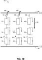
- Fig. 1B illustrates an example of a second photovoltaic arrangement 150 having a plurality of photovoltaic strings, where at least one photovoltaic string is installed incorrectly (e.g., installed backwards).
- the second photovoltaic arrangement 150 may comprise the first photovoltaic string 106, the second photovoltaic string 108, and a fourth photovoltaic string 152.
- the fourth photovoltaic string 152 may comprise a tenth photovoltaic panel 154, an eleventh photovoltaic panel 156, and a twelfth photovoltaic panel 158.
- a fourth fuse 160 may be installed for the fourth photovoltaic string 152.
- the fourth fuse 160 may be configured to open in order to interrupt excessive current from the fourth photovoltaic string 152, such as due to a short circuit.
- An installer of the second photovoltaic arrangement 150 may have installed the fourth photovoltaic string 152 incorrectly.
- the fourth photovoltaic string 152 may have been installed backwards such that a positive terminal may have been connected to the negative power line connection 104 and a negative terminal may have been connected to the positive power line connection 102.
- the first current 136 from the first photovoltaic string 106 and the second current 138 from the photovoltaic string 108 may be combined with current of the third photovoltaic string 152, resulting in an increased current 162 through the third photovoltaic string 152.
- the increased current 162 may cause the fourth fuse 160 to attempt to open in order to interrupt the increased current 162 that may otherwise result in damage to the second photovoltaic arrangement 150.
- the fourth fuse 160 may fail to open because the fourth photovoltaic string 152 may have an increased voltage greater than the open circuit voltage because the fourth photovoltaic string 152 is installed backward (e.g., the increased voltage may be twice the open circuit voltage because the fourth photovoltaic string 152 is connected in series instead of in parallel with the other photovoltaic strings because the fourth photovoltaic string 152 is installed backwards).
- a reverse polarity detection component may be configured to detect reverse polarity within the second photovoltaic arrangement 150.
- the reverse polarity detection component may be integrated into a fuse holder for the fourth fuse 160, and the reverse polarity detection component may provide a reverse polarity indication of reverse polarity before the fourth fuse 160 is installed into the fuse holder and the circuit is closed. In this way, an installer of the fourth fuse 160 may be provided with a warning of the reverse polarity before the fourth fuse 160 is installed and the circuit is closed.
- the fourth fuse 160 may be rated according to the open circuit voltage of the fourth photovoltaic string 152 as opposed to twice the open circuit voltage (e.g., because the installer may be warned before installing the fourth fuse 160 and closing the circuit, which would otherwise result in an increased voltage being applied to the fourth fuse 160 due to the backwards installation of the fourth photovoltaic string 152), which may otherwise substantially increase the cost of fuses for the second photovoltaic arrangement 150.
- the fourth fuse 160 may be rated less than two times the open circuit voltage of the fourth photovoltaic string 152.
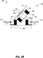
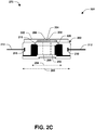
- Figs. 2A-2C illustrate examples of a fuse holder 201.
- the fuse holder 201 may comprise a fuse holder body 202 configured to receive and house a fuse (e.g., fuse 252 of Figs. 2B and 2C ).
- the fuse holder 201 may be installed along a power line over which a photovoltaic string provides DC power.
- the fuse holder may be installed within a fuse holder installation arrangement of a photovoltaic string combiner configured to combine a set of photovoltaic strings of a photovoltaic arrangement in parallel.
- the fuse holder 201 may comprise a fuse holder body input 216 and a fuse holder body output 210.
- the fuse holder body input 216 may be configured to connect to an output connection line 214 of the photovoltaic string.
- the fuse holder body output 210 may be configured to connect to an input connection line 212 for a component to which the photovoltaic string provides DC power, such as an inverter configured to convert DC power to AC power.
- the fuse holder body 202 may be configured to provide galvanic isolation between the fuse holder body input 216 and the fuse holder body output 210 when the fuse holder body 202 is in an open position and/or when the fuse 252 is not installed in the fuse holder body 202.
- the fuse holder body 202 may have a fuse holder body length 203 that is at least 1.5 times (e.g., 2 times, etc.) a fuse length 254 of the fuse 252, as illustrated in Figs. 2B and 2C , so that the fuse holder body 202 will not experience an issue with having reverse voltage on the fuse holder 201 in the event the photovoltaic string is installed backwards.
- the fuse holder body is configured to withstand (e.g., is rated for) about double (e.g., more than double) a rated voltage of the fuse.
- the fuse holder body 202 may comprise a fuse holder body cover 222 that may open to provide access for insertion of the fuse 252 into a fuse holder arrangement 205 for installation of the fuse 252 within the fuse holder 201.
- the fuse holder 201 may comprise a reverse polarity detection component 204 electrically coupled to the fuse holder body input 216 by a first indicator contact plate 218 and electrically coupled to the fuse holder body output 210 by a second indicator contact plate 220 so that the reverse polarity detection component 204 may evaluate a polarity of DC power provided by the photovoltaic string to the fuse holder body input 216.
- the reverse polarity detection component 204 may be configured to identify the polarity of the photovoltaic string when the fuse 252 is not installed within the fuse holder body 202.
- the reverse polarity detection component 204 may provide a reverse polarity indication of the reverse polarity (e.g., an audible alert such as a noise, a visible alert such as a light or a blinking light, a lockout mechanism to prohibit installation of the fuse 252 into the fuse holder 201, a message sent over a network such as a wired or wireless network to a device such as a mobile device or a server, etc.).
- a reverse polarity indication of the reverse polarity e.g., an audible alert such as a noise, a visible alert such as a light or a blinking light, a lockout mechanism to prohibit installation of the fuse 252 into the fuse holder 201, a message sent over a network such as a wired or wireless network to a device such as a mobile device or a server, etc.
- the fuse holder 201 may comprise a first indicator light 206 (e.g., a first light emitting diode (LED) having a first color) and a second indicator light 208 (e.g., a second LED having a second color). Responsive to the polarity being indicative of the reverse polarity (e.g., the photovoltaic string is connected backwards), the reverse polarity detection component 204 may be configured to provide the reverse polarity indication through the first indicator light 206 (e.g., the first indicator light 206 may be illuminated or blinked).
- a first indicator light 206 e.g., a first light emitting diode (LED) having a first color
- a second indicator light 208 e.g., a second LED having a second color
- the reverse polarity detection component 204 Responsive to the polarity being indicative of the reverse polarity (e.g., the photovoltaic string is connected backwards), the reverse polarity detection
- a normal polarity indication may be provided through the second indicator light 208 (e.g., the second indicator light may be illuminated or blinked). It may be appreciated that any number or configuration of visible indicators, such as a single indicator light or a multicolored indicator light, may be used to alert a user of the reverse polarity.
- Fig. 2B illustrates an example 250 of the fuse holder body cover 222 being opened into an open position for installation of the fuse 252.
- the fuse 252 may be inserted into the fuse holder arrangement 205 that is configured to hold the fuse 252 in place for installation.
- Fig. 2C illustrates an example 270 of the fuse holder body cover 222 being closed into a closed position to complete installation of the fuse 252, such that DC power from the photovoltaic string may flow into the fuse holder body input 216, through the fuse 252, and out through the fuse holder body output 210.
- the reverse polarity detection circuit 206 may bypass reverse polarity detection when the fuse holder body cover 222 is in the open position and/or when the fuse 252 is installed within the fuse holder 201.
- the fuse holder 201 may be configured to function as a blown fuse indicator when the fuse 252 is installed within the fuse holder 201.
- the fuse 252 may have a rating, such as a voltage rating, corresponding to an open circuit voltage of the photovoltaic string. In an example, the fuse 252 may be rated less than two times the open circuit voltage of the photovoltaic string.
- Fig. 3 illustrates an example 300 of a fuse holder 301.
- the fuse holder 301 may comprise a fuse holder body 302 configured to receive a fuse.
- the fuse holder 301 may comprise a reverse polarity detection component 304.
- the reverse polarity detection component 304 may be configured to identify a polarity of a direct current source, such as a photovoltaic string or other source that provides DC power. Responsive to the polarity being indicative of a reverse polarity, the reverse polarity detection component 304 may provide an audible alert 308 of the reverse polarity. For example, the audible alert 308 may be provided through a speaker 306 of the fuse holder 301.
- an installer that is to install a fuse within the fuse holder 301 may be provided with the audible alert 308 before installation of the fuse in the event a reverse polarity event is detected so that the installer may address a cause of the reverse polarity event (e.g., the installer can reinstall the photovoltaic string so that the photovoltaic string is not installed backwards) before installing the fuse and closing the circuit.
- a reverse polarity event e.g., the installer can reinstall the photovoltaic string so that the photovoltaic string is not installed backwards
- Figs. 4A and 4B illustrate examples of a fuse holder 401.
- Fig. 4A illustrates an example 400 of the fuse holder 401 comprising a fuse holder body 402 configured to receive a fuse.
- the fuse holder 401 may comprise a reverse polarity detection component 404 configured to provide an audible alert 408 through a speaker 406 responsive to identifying a reverse polarity of a photovoltaic string or other direct current source.
- the fuse holder body 402 may comprise a fuse holder body cover 422 that may be opened in order to provide access into the fuse holder body 402 for installation of the fuse.
- the fuse holder body 402 may comprise a locking mechanism 426, such as a solenoid, connected to the reverse polarity detection component 404 by an electrical connection 424.
- the locking mechanism 426 may be attached to the fuse holder body cover 422.
- the locking mechanism 426 may house a lock 428 configured to retract into the locking mechanism 426 when the reverse polarity detection component 404 determines that a polarity of the photovoltaic string is normal, and thus the fuse holder body cover 422 may be opened so that a fuse may be installed into the fuse holder 401.
- the lock 428 may be configured to extend out from the locking mechanism 426 so that the fuse holder body cover 422 is unable to be opened. It may be appreciated that any configuration, size, position, mechanism type, and/or lock type is contemplated for the locking mechanism 426 and lock 428 (e.g., the locking mechanism 426 may be positioned at any location inside or outside the fuse holder 401).
- Fig. 4B illustrates the example 450 of the reverse polarity detection component 404 invoking the locking mechanism 426 to lock the fuse holder body 402 to prohibit installation of the fuse based upon the photovoltaic string having the reverse polarity.
- the reverse polarity detection component 404 may send a signal over the electrical connection 424 to the locking mechanism 426.
- the signal may invoke the locking mechanism 426 to extend the lock 428, such as by applying a force to push the lock 428, so that the lock 428 prohibits a user from opening the fuse holder body cover 422.
- the lock 428 may encounter (e.g., contact, engage, abut against, etc.) a portion 402a of the fuse holder body 402 to limit movement of the lock 428 and the fuse holder body cover 422 so that a user is unable to open the fuse holder body cover 422 for installation of the fuse while the reverse polarity is detected.
- the reverse polarity detection component 404 may provide the audible alert 408 through the speaker 406 based upon the reverse polarity.
- Figs. 5A and 5B illustrate examples of a fuse holder 501.
- Fig. 5A illustrates an example 500 of the fuse holder 501 comprising a fuse holder body 502 configured to receive a fuse.
- the fuse holder 501 may comprise a reverse polarity detection component 504 configured to evaluate a polarity of a photovoltaic string or other direct current source.
- the fuse holder body 502 may comprise a fuse holder body cover 522 that may be opened in order to provide access into the fuse holder body 502 for installation of the fuse.
- the fuse holder body 502 may comprise a locking mechanism 526, such as a solenoid, connected to the reverse polarity detection component 504. In an example, the locking mechanism 526 may be attached to the fuse holder body cover 522.
- the locking mechanism 526 may house a lock 528 configured to retract into the locking mechanism 526 when the reverse polarity detection component 504 determines that a polarity of the photovoltaic string is normal.
- the lock 528 may be configured to extend out from the locking mechanism 526 to block insertion of the fuse into a fuse holder arrangement 505 for installation of the fuse. It may be appreciated that any configuration, size, position, mechanism type, and/or lock type is contemplated for the locking mechanism 526 and lock 528 (e.g., the locking mechanism 526 may be positioned at any location inside or outside the fuse holder 501).
- Fig. 5B illustrates an example 550 of the reverse polarity detection component 504 invoking the locking mechanism 526 to extend the lock 528 through the fuse holder arrangement in order to block installation of a fuse 552 based upon the photovoltaic string having the reverse polarity.
- the lock 528 may protrude out from the locking mechanism 526 into the fuse holder arrangement 505. While the lock 528 is protruding into the fuse holder arrangement 505, the fuse 552 may be blocked from being inserted into the fuse holder arrangement 505 for installation into the fuse holder 501.
- Fig. 6 illustrates an example of a system 600 for detecting reverse polarity of a photovoltaic system and/or a direct current system.
- the system 600 may comprise a reverse polarity detection component 604.
- the reverse polarity detection component 604 may comprise a resistor 606, a first diode 608, a second diode 610, and/or any other components used to identify polarity of a direct current source.
- the reverse polarity detection component 604 may be coupled to a direct current source, such as a photovoltaic string of photovoltaic panels.
- the reverse polarity detection component 604 may be configured to identify a polarity of DC power provided by the direct current source.
- the first diode 608 and the second diode 610 may be associated with one or more indicator lights, such as a bicolor light emitting diode (LED). Responsive to the polarity being a normal polarity, the second diode 610 may illuminate 614 the bicolor LED a first color to indicate that the direct current source has the normal polarity (e.g., that the direct current source is not installed backwards). Responsive to the polarity being a reverse polarity, the first diode 608 may illuminate 612 the bicolor LED a second color to indicate that the direct current source has the reverse polarity (e.g., that the direct current source is installed backwards).
- LED bicolor light emitting diode
- FIG. 7 illustrates an example of a system 700 for detecting reverse polarity of a photovoltaic arrangement 702.
- a photovoltaic string combiner 704 may be configured to combine one or more photovoltaic strings (e.g., a string of photovoltaic panels connected in series) in parallel.
- the photovoltaic string combiner 704 may comprise a fuse holder installation arrangement configured to receive a fuse holder 706 for installation.
- the fuse holder 706 may comprise a fuse holder body configured to receive a fuse used to protect against damage from excessive current occurring from the photovoltaic arrangement 702, such as due to a short circuit.
- the fuse holder 706 may have a fuse holder body input connected to a photovoltaic string of the photovoltaic arrangement 702 so that DC power from the photovoltaic arrangement 702 is received through the fuse holder body input and is directed through the fuse.
- the fuse holder 706 may have a fuse holder body output that connects to an inverter 710. After the DC power passes through the fuse, the DC power may be output through the fuse holder body output to the inverter 710.
- the inverter 710 may be configured to convert the DC power to AC power, such as for an AC power grid (e.g., to power a building).
- the fuse holder 706 may comprise a reverse polarity detection component 708 configured to evaluate the DC power to determine a polarity of the photovoltaic string.
- the reverse polarity detection component 708 may provide a reverse polarity indication, such as blinking a light, providing an audible alert, sending a message across a network (e.g., a message sent over a wireless connection to a mobile device such as a smart phone of a user; a message sent over a network to which the photovoltaic string combiner 704 is connected; etc.), etc.
- a reverse polarity indication such as blinking a light
- an audible alert sending a message across a network
- the photovoltaic string combiner 704 and the inverter 710 may be integrated into the same device, such as a single residential inverter product.
- first,” “second,” and/or the like are not intended to imply a temporal aspect, a spatial aspect, an ordering, etc. Rather, such terms are merely used as identifiers, names, etc. for features, elements, items, etc.
- a first object and a second object generally correspond to object A and object B or two different or two identical objects or the same object.
Landscapes
- Photovoltaic Devices (AREA)
- Fuses (AREA)
Claims (13)
- System zur Erkennung von Umkehrpolarität einer Photovoltaikanlage umfassend: einen Sicherungshalter (201, 301) umfassend:einen Sicherungshalterkörper (202, 302), der für die Aufnahme einer Sicherung (252) konfiguriert ist; undeine Komponente zur Erkennung von Umkehrpolarität (204, 304), die so konfiguriert ist, dass sie:eine Polarität eines Photovoltaikstrangs (106, 108, 110, 152) einer Photovoltaikanordnung (100, 150) identifiziert; undals Reaktion darauf, dass die Polarität auf eine Umkehrpolarität hindeutet, einen Hinweis auf die Umkehrpolarität gibt;wobei der Sicherungshalterkörper (202, 302) ferner so konfiguriert ist, dass er eine galvanische Trennung zwischen einem Sicherungshalterkörpereingang (216) und einem Sicherungshalterkörperausgang (210) des Sicherungshalterkörpers (202) bereitstellt, wenn sich der Sicherungshalterkörper (202) in einer offenen Position befindet und/oder, wenn die Sicherung (252) nicht im Sicherungshalterkörper (202, 302) eingesetzt ist.
- System nach Anspruch 1, wobei der Sicherungshalterkörper Folgendes umfasst: einen Verschlussmechanismus (426, 526), der so konfiguriert ist, dass er den Sicherungshalterkörper (202) verschließt, um das Einsetzen der Sicherung auf der Grundlage zu verhindern, dass der Photovoltaikstrang die Umkehrpolarität aufweist.
- System nach Anspruch 2, wobei der Verschlussmechanismus (526) eine Magnetspule umfasst.
- System nach Anspruch 1, wobei der Sicherungshalter (201) eine erste Anzeigelampe (206) und eine zweite Anzeigelampe (208) umfasst und die Komponente zur Erkennung von Umkehrpolarität (204) so konfiguriert ist, dass sie:als Reaktion darauf, dass die Polarität auf eine Umkehrpolarität hindeutet, den Hinweis auf die Umkehrpolarität durch die erste Anzeigelampe (206) bereitstellt; undals Reaktion darauf, dass die Polarität auf eine Normalpolarität hindeutet, den Hinweis auf die Normalpolarität durch die zweite Anzeigelampe (208) bereitstellt.
- System nach Anspruch 1, wobei die Komponente zur Erkennung von Umkehrpolarität (304) so konfiguriert ist, dass der Hinweis auf die Umkehrpolarität als akustisches Warnsignal erfolgt (308).
- System nach Anspruch 1, wobei der Sicherungshalterkörper (202) so konfiguriert ist, dass er der doppelten Nennspannung der Sicherung standhält.
- System nach Anspruch 1, wobei die Komponente zur Erkennung von Umkehrpolarität (204) so konfiguriert ist, dass sie die Erkennung der Umkehrpolarität überbrückt, wenn die Sicherung (252) im Sicherungshalterkörper (202) eingesetzt ist.
- System nach Anspruch 1, wobei die Sicherung (252) eine Nennleistung hat, die einer Leerlaufspannung der Photovoltaikanordnung (100, 150) entspricht.
- System nach Anspruch 1 umfassend:
einen Photovoltaikstrang-Kombinator (704), der so konfiguriert ist, dass er einen Satz von Photovoltaiksträngen (106, 108, 110, 152) der Photovoltaikanordnung (100, 150) kombiniert, wobei der Photovoltaikstrang-Kombinator (704) Folgendes umfasst:
eine Sicherungshalter-Einbauanordnung, die so konfiguriert ist, dass sie den Sicherungshalter (706) zum Einsetzen aufnimmt. - System nach Anspruch 9, wobei der Photovoltaikstrang-Kombinator (704) einen Gleichstrom-Ausgangsanschluss an einen Wechselrichter (710) umfasst, wobei der Wechselrichter (710) so konfiguriert ist, dass er Gleichstromleistung, die von der Photovoltaikanordnung (100, 150) durch den Photovoltaikstrang-Kombinator (704) bereitgestellt wird, in Wechselstromleistung umwandelt.
- System nach Anspruch 1, wobei der Sicherungshalter (201) so konfiguriert ist, dass er als Indikator für eine durchgebrannte Sicherung für den Photovoltaikstrang fungiert, wenn die Sicherung (252) im Sicherungshalter (201) eingesetzt ist.
- Verfahren zur Erkennung von Umkehrpolarität einer Photovoltaikanlage umfassend:Identifizieren einer Polarität eines Photovoltaikstrangs (106, 108, 110, 152) einer Photovoltaikanordnung (100, 150), wobei der Photovoltaikstrang (106, 108, 110, 152) so konfiguriert ist, dass er mit einem Sicherungshalter (201, 301) verbunden wird, der einen Sicherungshalterkörper (202, 302) umfasst, der so konfiguriert ist, dass er eine Sicherung (252) für den Photovoltaikstrang (106, 108, 110, 152) aufnimmt; und als Reaktion darauf, dass die Polarität auf eine Umkehrpolarität hindeutet, einen Hinweis auf die Umkehrpolarität gibt; undBereitstellen einer galvanischen Trennung zwischen einem Sicherungshalterkörpereingang (216) und einem Sicherungshalterkörperausgang (210) des Sicherungshalterkörpers (202), wenn sich der Sicherungshalterkörper (202) in einer offenen Position befindet und/oder wenn die Sicherung (252) nicht im Sicherungshalterkörper (202, 302) eingesetzt ist.
- Verfahren nach Anspruch 12, umfassend: als Reaktion darauf, dass die Polarität
auf eine Umkehrpolarität hindeutet, den Hinweis auf die Umkehrpolarität durch die erste Anzeigelampe (206) bereitstellt; und
als Reaktion darauf, dass die Polarität auf eine Normalpolarität hindeutet, den Hinweis auf die Normalpolarität durch eine zweite Anzeigelampe (208) bereitstellt.
Applications Claiming Priority (2)
| Application Number | Priority Date | Filing Date | Title |
|---|---|---|---|
| US201562119208P | 2015-02-22 | 2015-02-22 | |
| PCT/US2016/018890 WO2016134356A1 (en) | 2015-02-22 | 2016-02-22 | Photovoltaic string reverse polarity detection |
Publications (2)
| Publication Number | Publication Date |
|---|---|
| EP3259841A1 EP3259841A1 (de) | 2017-12-27 |
| EP3259841B1 true EP3259841B1 (de) | 2020-10-07 |
Family
ID=56689496
Family Applications (1)
| Application Number | Title | Priority Date | Filing Date |
|---|---|---|---|
| EP16706774.3A Not-in-force EP3259841B1 (de) | 2015-02-22 | 2016-02-22 | Erkennung von umkehrpolarität bei in reihe geschalteten fotovoltaikmodulen |
Country Status (6)
| Country | Link |
|---|---|
| US (1) | US10404060B2 (de) |
| EP (1) | EP3259841B1 (de) |
| CN (1) | CN107454992B (de) |
| AU (1) | AU2016219770A1 (de) |
| ES (1) | ES2832823T3 (de) |
| WO (1) | WO2016134356A1 (de) |
Families Citing this family (5)
| Publication number | Priority date | Publication date | Assignee | Title |
|---|---|---|---|---|
| CN114285375B (zh) * | 2021-12-30 | 2024-07-16 | 安徽尚能新能源科技有限公司 | 一种光伏组串反接检测方法及装置 |
| CN114720913B (zh) * | 2022-03-04 | 2025-08-15 | 固德威电源科技(广德)有限公司 | 一种用于光伏系统的并联组串反接的检测系统及检测方法 |
| CN115021324B (zh) * | 2022-08-09 | 2022-11-15 | 阳光电源股份有限公司 | 一种汇流设备、光伏系统及故障检测方法 |
| US12382520B2 (en) * | 2022-11-11 | 2025-08-05 | Tigo Energy, Inc. | Solar panel transmitter pairing process |
| CN116944724A (zh) * | 2023-08-09 | 2023-10-27 | 晶科能源股份有限公司 | 电池串的焊接方法以及串焊机 |
Family Cites Families (205)
| Publication number | Priority date | Publication date | Assignee | Title |
|---|---|---|---|---|
| US3387200A (en) | 1967-10-20 | 1968-06-04 | Fox Prod Co | Battery chargers with reverse polarity indicator |
| DE2148810B2 (de) | 1971-09-30 | 1975-09-18 | Robert Bosch Gmbh, 7000 Stuttgart | Stromversorgungseinrichtung |
| US4358810A (en) | 1981-01-21 | 1982-11-09 | Westinghouse Electric Corp. | Circuit breaker with alarm |
| CN1061288A (zh) | 1990-11-04 | 1992-05-20 | 夏敬释 | 蓄电池接入指导及报警装置 |
| US5229220A (en) | 1991-12-12 | 1993-07-20 | Motorola, Inc. | Reverse polarity protection assembly |
| US5338991A (en) | 1992-12-28 | 1994-08-16 | Lu Chao Cheng | High power solid state relay with input presence and polarity indication |
| US6075441A (en) * | 1996-09-05 | 2000-06-13 | Key-Trak, Inc. | Inventoriable-object control and tracking system |
| US6111767A (en) | 1998-06-22 | 2000-08-29 | Heliotronics, Inc. | Inverter integrated instrumentation having a current-voltage curve tracer |
| JP2000228529A (ja) | 1998-11-30 | 2000-08-15 | Canon Inc | 過電圧防止素子を有する太陽電池モジュール及びこれを用いた太陽光発電システム |
| DE10027879A1 (de) | 2000-05-30 | 2001-12-06 | Hans Appl | Umschalter für Gleichstrom mit optischer Indikation der Umpolung der Polarität |
| US6741435B1 (en) | 2000-08-09 | 2004-05-25 | Server Technology, Inc. | Power controller with DC ARC-supression relays |
| JP2002111038A (ja) | 2000-09-29 | 2002-04-12 | Canon Inc | 太陽電池モジュールおよびその製造方法、並びに、発電装置 |
| WO2002061914A2 (en) | 2001-01-29 | 2002-08-08 | Broadcom Corporation | Battery-operated power supply |
| US7612283B2 (en) | 2002-07-09 | 2009-11-03 | Canon Kabushiki Kaisha | Solar power generation apparatus and its manufacturing method |
| US6867704B2 (en) | 2003-02-28 | 2005-03-15 | Dell Products L.P. | Bi-color light source for indicating status of information handling system |
| AU2003266653A1 (en) | 2003-09-26 | 2005-04-14 | Niwa Electric Co., Ltd. | Inverter circuit and photovoltaic power generator |
| US7248946B2 (en) | 2004-05-11 | 2007-07-24 | Advanced Energy Conversion, Llc | Inverter control methodology for distributed generation sources connected to a utility grid |
| JP4133924B2 (ja) | 2004-05-14 | 2008-08-13 | Necトーキン株式会社 | 電源装置 |
| US8204709B2 (en) | 2005-01-18 | 2012-06-19 | Solar Sentry Corporation | System and method for monitoring photovoltaic power generation systems |
| US7432618B2 (en) | 2005-04-07 | 2008-10-07 | Pv Powered, Inc. | Inverter anti-islanding method |
| US20060237058A1 (en) | 2005-04-25 | 2006-10-26 | Mcclintock Ronald B | Direct current combiner box with power monitoring, ground fault detection and communications interface |
| US7388348B2 (en) | 2005-07-15 | 2008-06-17 | Mattichak Alan D | Portable solar energy system |
| DE102006004233A1 (de) | 2006-01-30 | 2007-08-09 | Siemens Ag Österreich | Kommunikationsstruktur für Solarwechselrichter |
| US7839665B2 (en) * | 2006-03-27 | 2010-11-23 | Mitsubishi Electric Corporation | System interconnection inverter including overvoltage and negative voltage protection |
| US7881297B2 (en) | 2006-09-01 | 2011-02-01 | Avaya Inc. | Providing communications including an extended protocol header |
| US7893346B2 (en) | 2006-09-28 | 2011-02-22 | Jack Nachamkin | Integrated voltaic energy system |
| ITPD20060382A1 (it) | 2006-10-13 | 2008-04-14 | Elettronica Santerno S P A | Inverter solare e impianto di conversione di energia solare in energia elettrica |
| DE502006004329D1 (de) | 2006-10-21 | 2009-09-03 | Sma Solar Technology Ag | Schaltungseinrichtung und Verfahren, insbesondere für Photovoltaik-Generatoren |
| US20080111517A1 (en) | 2006-11-15 | 2008-05-15 | Pfeifer John E | Charge Controller for DC-DC Power Conversion |
| US8384243B2 (en) | 2007-12-04 | 2013-02-26 | Solaredge Technologies Ltd. | Distributed power harvesting systems using DC power sources |
| US9112379B2 (en) | 2006-12-06 | 2015-08-18 | Solaredge Technologies Ltd. | Pairing of components in a direct current distributed power generation system |
| US8816535B2 (en) | 2007-10-10 | 2014-08-26 | Solaredge Technologies, Ltd. | System and method for protection during inverter shutdown in distributed power installations |
| US7821753B2 (en) | 2007-01-18 | 2010-10-26 | Alcatel-Lucent Usa Inc. | DC high power distribution assembly |
| DE202007001648U1 (de) | 2007-01-31 | 2007-09-13 | König, Peter | Vorrichtung zur Spannungsfreischaltung von Photovoltaikanlagen zur Ermöglichung des Einsatzes von Löschmitteln und zur sicheren Freischaltung von Netzen |
| US8158877B2 (en) | 2007-03-30 | 2012-04-17 | Sunpower Corporation | Localized power point optimizer for solar cell installations |
| EP1992691A1 (de) | 2007-05-16 | 2008-11-19 | Deutsches Krebsforschungszentrum, Stiftung des öffentlichen Rechts | Neue TTV-Sequenzen zur Diagnose, Prävention und Behandlung von Kinderleukämie |
| US20090000654A1 (en) | 2007-05-17 | 2009-01-01 | Larankelo, Inc. | Distributed inverter and intelligent gateway |
| US20080283118A1 (en) | 2007-05-17 | 2008-11-20 | Larankelo, Inc. | Photovoltaic ac inverter mount and interconnect |
| US7768751B2 (en) | 2008-01-29 | 2010-08-03 | Advanced Energy Industries, Inc. | System and method for ground fault detection and interruption |
| CN101919150B (zh) | 2007-09-18 | 2013-12-18 | 菲莱贝克能源公司 | 从局部能源产生具有低谐波畸变的交流功率的电流波形结构 |
| SG151142A1 (en) | 2007-10-02 | 2009-04-30 | Ettanoor Thuppale Mohan Dass | Switching device |
| EP2048679B1 (de) | 2007-10-12 | 2010-04-07 | SMA Solar Technology AG | Lasttrenner-Anordnung |
| CA2737134C (en) | 2007-10-15 | 2017-10-10 | Ampt, Llc | Systems for highly efficient solar power |
| US8933321B2 (en) | 2009-02-05 | 2015-01-13 | Tigo Energy, Inc. | Systems and methods for an enhanced watchdog in solar module installations |
| CN105244905B (zh) | 2007-12-05 | 2019-05-21 | 太阳能安吉有限公司 | 分布式电力装置中的安全机构、醒来和关闭方法 |
| WO2009081205A2 (en) | 2007-12-20 | 2009-07-02 | Enecsys Limited | Grid synchronisation |
| ITMI20080048A1 (it) | 2008-01-14 | 2009-07-15 | Abb Spa | Unita' elettronica di protezione per interruttori automatici e procedimento relativo. |
| US20090207543A1 (en) | 2008-02-14 | 2009-08-20 | Independent Power Systems, Inc. | System and method for fault detection and hazard prevention in photovoltaic source and output circuits |
| US8080899B2 (en) | 2008-02-21 | 2011-12-20 | Stellaris Corporation | Photovoltaic ladder inverter |
| CN201196666Y (zh) | 2008-04-03 | 2009-02-18 | 张骞宁 | 电源极性判别器 |
| US8289183B1 (en) | 2008-04-25 | 2012-10-16 | Texas Instruments Incorporated | System and method for solar panel array analysis |
| US8023266B2 (en) | 2008-05-20 | 2011-09-20 | Greenray Inc. | AC photovoltaic module and inverter assembly |
| US8762083B2 (en) * | 2008-07-28 | 2014-06-24 | Littelfuse, Inc. | Intelligent fuse holder and circuit protection methods |
| US20100019913A1 (en) * | 2008-07-28 | 2010-01-28 | Littelfuse, Inc. | Circuit protection system having failure mode indication |
| DE102008048841B8 (de) | 2008-09-25 | 2010-06-10 | Fraunhofer-Gesellschaft zur Förderung der angewandten Forschung e.V. | Trennschaltung für Wechselrichter |
| WO2010042533A2 (en) | 2008-10-06 | 2010-04-15 | Atonometrics, Inc. | Photovoltaic module performance monitoring system and devices |
| DE102008052037B3 (de) | 2008-10-16 | 2010-04-08 | Moeller Gmbh | Solarmodul |
| US8860241B2 (en) | 2008-11-26 | 2014-10-14 | Tigo Energy, Inc. | Systems and methods for using a power converter for transmission of data over the power feed |
| DE102009004679B3 (de) | 2009-01-12 | 2010-06-17 | Schott Solar Ag | Stromversorgungssystem und Photovoltaik-Einrichtung dafür |
| WO2010091244A2 (en) | 2009-02-05 | 2010-08-12 | Enphase Energy, Inc. | Method and apparatus for determining a corrected monitoring voltage |
| EP2219276B1 (de) | 2009-02-11 | 2015-12-02 | SMA Solar Technology AG | Photovoltaikanlage zur dreiphasigen Einspeisung in ein elektrisches Energieversorgungsnetz |
| AT508104B1 (de) | 2009-02-12 | 2015-05-15 | Fronius Int Gmbh | Photovoltaikanlage mit mehreren wechselrichtern, wechselrichter, usb-massenspeichergerät und verfahren zum durchführen von software-updates an wechselrichtern |
| ES2385912T3 (es) | 2009-04-17 | 2012-08-03 | Sma Solar Technology Ag | Procedimiento y dispositivo para conectar una planta fotovoltaica a una red de corriente alterna |
| JP5247883B2 (ja) | 2009-06-24 | 2013-07-24 | 三菱電機株式会社 | 電力変換システムおよび通信アドレス設定方法 |
| US8638011B2 (en) | 2009-07-10 | 2014-01-28 | Protonex Technology Corporation | Portable power manager operating methods |
| CA2767867C (en) | 2009-07-16 | 2018-11-13 | General Cybernation Group, Inc. | Smart and scalable power inverters |
| EP2457313B1 (de) | 2009-07-23 | 2014-03-05 | Enphase Energy, Inc. | Verfahren und vorrichtung zur erkennung und kontrolle von dc-störlichtbögen |
| US9312697B2 (en) | 2009-07-30 | 2016-04-12 | Tigo Energy, Inc. | System and method for addressing solar energy production capacity loss due to field buildup between cells and glass and frame assembly |
| EP2282388A1 (de) | 2009-08-06 | 2011-02-09 | SMA Solar Technology AG | Vorrichtung zur Einspeisung elektrischer Energie von einer Vielzahl von Strings von Photovoltaikmodulen in ein Stromnetz |
| ATE555531T1 (de) * | 2009-08-06 | 2012-05-15 | Sma Solar Technology Ag | Rückstromsensor für parallel geschaltete solarmodule |
| US8410950B2 (en) | 2009-08-17 | 2013-04-02 | Paceco Corp. | Photovoltaic panel monitoring apparatus |
| US20110044083A1 (en) | 2009-08-20 | 2011-02-24 | Christopher Thompson | Adaptive Photovoltaic Inverter |
| US8314375B2 (en) | 2009-08-21 | 2012-11-20 | Tigo Energy, Inc. | System and method for local string management unit |
| CA2772573A1 (en) | 2009-08-28 | 2011-03-03 | Enphase Energy, Inc. | Power line communications apparatus |
| US8558102B2 (en) | 2009-09-11 | 2013-10-15 | Miasole | Rotatable junction box for a solar module |
| US20110088743A1 (en) | 2009-10-15 | 2011-04-21 | Yuhao Luo | Method to manage a photovoltaic system |
| US8859884B2 (en) | 2009-10-19 | 2014-10-14 | Helios Focus Llc | Solar photovoltaic module safety shutdown system |
| US9172312B2 (en) | 2009-11-25 | 2015-10-27 | American Superconductor Corporation | Reducing photovoltaic array voltage during inverter re-enablement |
| DE202009016164U1 (de) | 2009-11-26 | 2010-03-04 | Carlo Gavazzi Services Ag | Steuerungsvorrichtung für Fotovoltaikmodule |
| GB2478695A (en) | 2009-12-24 | 2011-09-21 | David Gordon | Combined wind turbine and street light including a power regulator allowing electrical connection on the mains power supply side of an electricity meter. |
| CN102109578A (zh) | 2009-12-24 | 2011-06-29 | 叶明宝 | 光伏电池组件串监测 |
| US8773236B2 (en) | 2009-12-29 | 2014-07-08 | Tigo Energy, Inc. | Systems and methods for a communication protocol between a local controller and a master controller |
| US8854193B2 (en) | 2009-12-29 | 2014-10-07 | Tigo Energy, Inc. | Systems and methods for remote or local shut-off of a photovoltaic system |
| US8860242B1 (en) | 2009-12-31 | 2014-10-14 | Solarbridge Technologies, Inc. | Power-line communication coupling |
| IT1399247B1 (it) | 2010-01-27 | 2013-04-11 | Aepi Costruzioni Elettromeccaniche S R L | Sistema di ricetrasmissione di segnali in un impianto di produzione di energia e relativo metodo di trasmissione. |
| EP2352178A1 (de) | 2010-01-29 | 2011-08-03 | Saint-Gobain Glass France | Solarmodulanordnungen und Diodenkabel |
| US8334489B2 (en) | 2010-03-10 | 2012-12-18 | Sunpower Corporation | Photovoltaic system with managed output and method of managing variability of output from a photovoltaic system |
| US20110222327A1 (en) | 2010-03-11 | 2011-09-15 | Christopher Thompson | Photovoltaic Inverter Power System |
| US8338989B2 (en) | 2010-03-11 | 2012-12-25 | First Solar, Inc. | Inverter power system |
| US9312399B2 (en) | 2010-04-02 | 2016-04-12 | Tigo Energy, Inc. | Systems and methods for mapping the connectivity topology of local management units in photovoltaic arrays |
| ES2729486T3 (es) | 2010-04-22 | 2019-11-04 | Tigo Energy Inc | Sistema y método para la vigilancia mejorada en instalaciones de paneles solares |
| DE102010017747A1 (de) | 2010-05-03 | 2011-11-03 | Sma Solar Technology Ag | Verfahren zur Begrenzung der Generatorspannung einer photovoltaischen Anlage im Gefahrenfall und photovoltaische Anlage |
| DE102010019267B4 (de) | 2010-05-04 | 2012-08-30 | Adensis Gmbh | Photovoltaikanlage mit gezielter Fehlanpassung an den MPP und zugehöriges Betriebsverfahren |
| US20110138377A1 (en) | 2010-05-04 | 2011-06-09 | Phat Energy Corporation | Renewable Energy Monitoring System & Method |
| DE102010028679B4 (de) | 2010-05-06 | 2020-08-06 | Wöhner GmbH & Co. KG Elektrotechnische Systeme | Sicherungsaufnahmevorrichtung, insbesondere für Anschlusskästen von Photovoltaikanlagen |
| IT1400921B1 (it) | 2010-05-14 | 2013-07-02 | St Microelectronics Srl | Diodo di by-pass o interruttore realizzato con un mosfet a bassa resistenza di conduzione e relativo circuito di controllo autoalimentato |
| US9583946B2 (en) | 2010-05-27 | 2017-02-28 | Enphase Energy, Inc. | Method and apparatus for power converter input voltage regulation |
| US20140360561A1 (en) | 2010-06-15 | 2014-12-11 | Tenksolar, Inc. | Fully redundant photovoltaic array |
| US8395919B2 (en) | 2010-07-29 | 2013-03-12 | General Electric Company | Photovoltaic inverter system and method of starting same at high open-circuit voltage |
| US8455752B2 (en) | 2010-07-29 | 2013-06-04 | General Electric Company | Integral ac module grounding system |
| US8350414B2 (en) | 2010-08-11 | 2013-01-08 | Xantrex Technology Inc. | Semiconductor assisted DC load break contactor |
| US8466706B2 (en) | 2010-08-17 | 2013-06-18 | Schneider Electric USA, Inc. | Solar combiner with integrated string current monitoring |
| US10615743B2 (en) | 2010-08-24 | 2020-04-07 | David Crites | Active and passive monitoring system for installed photovoltaic strings, substrings, and modules |
| US20120053867A1 (en) | 2010-08-24 | 2012-03-01 | Atonometrics, Inc. | System and methods for high-precision string-level measurement of photovoltaic array performance |
| US10347775B2 (en) | 2010-08-30 | 2019-07-09 | Shoals Technologies Group, Llc | Solar array recombiner box with wireless monitoring capability |
| IT1402184B1 (it) | 2010-09-16 | 2013-08-28 | Bitron Spa | Caricabatterie da pannello fotovoltaico. |
| DE102010049293B3 (de) | 2010-09-21 | 2012-02-16 | VWL Umweltcentrum für Haustechnik GmbH | Anordnung zum sicheren Außerbetriebsetzen von Photovoltaikanlagen |
| US8482893B2 (en) | 2010-09-28 | 2013-07-09 | Xantrex Technology Inc. | Integrated photovoltaic source circuit combiner and protection subsystem |
| IT1402433B1 (it) | 2010-09-29 | 2013-09-04 | St Microelectronics Srl | Sistema automatico di abilitazione/disabilitazione sincrona di pannelli fotovoltaici di un impianto a conversione dc/dc distribuita |
| US8576591B2 (en) | 2010-09-30 | 2013-11-05 | Astec International Limited | Converters and inverters for photovoltaic power systems |
| US8725437B2 (en) | 2010-10-05 | 2014-05-13 | Also Energy, Llc | System and method for monitoring performance of a photovoltaic array |
| JPWO2012046331A1 (ja) * | 2010-10-07 | 2014-02-24 | 東芝三菱電機産業システム株式会社 | 故障検出装置 |
| FR2966296B1 (fr) | 2010-10-15 | 2013-03-22 | Schneider Electric Ind Sas | Protection pour le branchement d'une source continue sur un equipement electronique |
| CN201820311U (zh) | 2010-10-21 | 2011-05-04 | 陕西荣森网络科技有限公司 | 智能型全自动声光电警示设备 |
| GB2485335B (en) | 2010-10-25 | 2012-10-03 | Enecsys Ltd | Renewable energy monitoring system |
| DE102010060633B3 (de) | 2010-11-17 | 2012-04-26 | Sma Solar Technology Ag | Verfahren zum Verbinden einer Photovoltaikanlage mit einem Stromversorgungsnetz und Photovoltaikanlage zur Durchführung des Verfahrens |
| TWI530043B (zh) | 2010-12-07 | 2016-04-11 | 創惟科技股份有限公司 | 接線盒、電力系統及其控制方法 |
| JP5674443B2 (ja) | 2010-12-08 | 2015-02-25 | 株式会社東芝 | 太陽電池モジュールおよび太陽電池モジュールのコネクタ |
| GB2486408A (en) | 2010-12-09 | 2012-06-20 | Solaredge Technologies Ltd | Disconnection of a string carrying direct current |
| EP2466407A1 (de) | 2010-12-17 | 2012-06-20 | Solare Datensysteme GmbH | Überwachung von Umrichtern in einem photovoltaischen System |
| GB2483317B (en) | 2011-01-12 | 2012-08-22 | Solaredge Technologies Ltd | Serially connected inverters |
| US8547669B2 (en) | 2011-01-12 | 2013-10-01 | Schneider Electric USA, Inc. | Arc fault mitigation for photovoltaic systems |
| US9366714B2 (en) | 2011-01-21 | 2016-06-14 | Ampt, Llc | Abnormality detection architecture and methods for photovoltaic systems |
| US8716999B2 (en) | 2011-02-10 | 2014-05-06 | Draker, Inc. | Dynamic frequency and pulse-width modulation of dual-mode switching power controllers in photovoltaic arrays |
| US8922062B2 (en) | 2011-03-14 | 2014-12-30 | Sunpower Corporation | Automatic voltage regulation for photovoltaic systems |
| US20120242320A1 (en) | 2011-03-22 | 2012-09-27 | Fischer Kevin C | Automatic Generation And Analysis Of Solar Cell IV Curves |
| DE102011015221A1 (de) | 2011-03-25 | 2012-09-27 | Phoenix Contact Gmbh & Co. Kg | Kommunikationssystem mit überwachtem Abschaltverhalten und Abschalt-Beschleunigungseinrichtung |
| CN202004452U (zh) | 2011-03-31 | 2011-10-05 | 上海美科新能源股份有限公司 | 一种光伏逆变器的可控放电电路 |
| US20120256584A1 (en) | 2011-04-05 | 2012-10-11 | Crites David E | PV monitoring system with combiner switching and charge controller switching |
| CN102157966B (zh) | 2011-04-12 | 2013-03-06 | 江西日普升太阳能光伏产业有限公司 | 多功能智能光伏控制器 |
| CN201994659U (zh) * | 2011-04-22 | 2011-09-28 | 北京科诺伟业科技有限公司 | 一种太阳能光伏充电控制器防反接保护电路 |
| DE102011018972B4 (de) | 2011-04-28 | 2017-06-08 | Guido Panter | Solarmodulschutzvorrichtung |
| US8829715B2 (en) | 2011-04-29 | 2014-09-09 | General Electric Company | Switching coordination of distributed dc-dc converters for highly efficient photovoltaic power plants |
| US8937822B2 (en) | 2011-05-08 | 2015-01-20 | Paul Wilkinson Dent | Solar energy conversion and utilization system |
| CN102185507B (zh) | 2011-05-11 | 2013-10-30 | 浙江昱能光伏科技集成有限公司 | 太阳能光伏三相微逆变器以及太阳能光伏发电系统 |
| CN102867712A (zh) * | 2011-05-20 | 2013-01-09 | 中环光伏系统有限公司 | 用于太阳能电池组件串的断路器及保护方法 |
| DE102012010083B4 (de) | 2011-05-23 | 2023-04-27 | Microsemi Corp. | Photovoltaische Sicherheitsabschaltungsvorrichtung |
| US20130009483A1 (en) | 2011-05-31 | 2013-01-10 | Kawate Keith W | Power generator module connectivity control |
| US20120310427A1 (en) | 2011-05-31 | 2012-12-06 | Williams B Jeffery | Automatic Monitoring and Adjustment of a Solar Panel Array |
| US8923373B2 (en) | 2011-06-10 | 2014-12-30 | Didier Boivin | Powerline control interface in photovoltaic environment for frequency and amplitude modulation transmitter |
| ITMI20111057A1 (it) | 2011-06-13 | 2012-12-14 | Renzo Oldani | Apparecchiatura per il sezionamento di un flusso di energia elettrica in uno o piu' conduttori. |
| US20120319489A1 (en) | 2011-06-15 | 2012-12-20 | Mccaslin Shawn R | Power Shuffling Solar String Equalization System |
| US8710351B2 (en) | 2011-06-22 | 2014-04-29 | Steven Andrew Robbins | Solar power system with communication network utilizing magnetic fields |
| CN102193049B (zh) | 2011-06-23 | 2014-04-09 | 北京七星华创弗朗特电子有限公司 | 用于光伏逆变器的反极性报警电路 |
| CN202119876U (zh) | 2011-06-27 | 2012-01-18 | 天津大学 | 光伏阵列故障诊断监控箱 |
| US20130015875A1 (en) | 2011-07-13 | 2013-01-17 | United Solar Ovonic Llc | Failure detection system for photovoltaic array |
| US9142965B2 (en) | 2011-07-28 | 2015-09-22 | Tigo Energy, Inc. | Systems and methods to combine strings of solar panels |
| US20130033115A1 (en) | 2011-08-01 | 2013-02-07 | General Electric Company | Re-combiner box of photovoltaic system |
| US8723370B2 (en) | 2011-08-30 | 2014-05-13 | Renewable Power Conversion, Inc. | Photovoltaic string sub-combiner |
| US8687348B2 (en) | 2011-08-31 | 2014-04-01 | Bentek Corporation | Integrated safety disconnects for power systems |
| DE102011053524B4 (de) | 2011-09-12 | 2015-05-28 | Sma Solar Technology Ag | Sicherheitseinrichtung für eine Photovoltaikanlage und Verfahren zum Betreiben einer Sicherheitseinrichtung für eine Photovoltaikanlage |
| US8684758B2 (en) | 2011-10-03 | 2014-04-01 | Mersen Usa Newburyport-Ma, Llc | Terminal unit having fused combiner/distribution bus bar assembly |
| US9136732B2 (en) | 2011-10-15 | 2015-09-15 | James F Wolter | Distributed energy storage and power quality control in photovoltaic arrays |
| US9680301B2 (en) | 2011-10-27 | 2017-06-13 | Sunpower Corporation | Master-slave architecture for controlling operation of photovoltaic power plants |
| CN202309503U (zh) | 2011-11-10 | 2012-07-04 | 珠海天兆新能源技术有限公司 | 新型光伏并网逆变器igbt吸收电路 |
| US9397235B2 (en) | 2011-12-02 | 2016-07-19 | Schneider Elelctric Usa, Inc. | Photovoltaic string combiner with disconnect having provision for converting between grounded and ungrounded systems |
| US8787052B2 (en) | 2011-12-13 | 2014-07-22 | General Electric Company | Methods and systems for controlling a power conversion device |
| CN103166240A (zh) | 2011-12-15 | 2013-06-19 | 中国科学院电工研究所 | 并网太阳能光伏电站监测系统 |
| CN103197613B (zh) | 2012-01-09 | 2016-03-30 | 中国科学院沈阳自动化研究所 | 一种基于工业无线网络的光伏电站监控系统 |
| WO2013109797A1 (en) | 2012-01-17 | 2013-07-25 | Massachusetts Institute Of Technology | Enhanced stacked switched capacitor energy buffer circuit |
| JP5759911B2 (ja) * | 2012-01-30 | 2015-08-05 | Jx日鉱日石エネルギー株式会社 | 太陽電池ユニット及び太陽電池モジュール |
| GB2498791A (en) | 2012-01-30 | 2013-07-31 | Solaredge Technologies Ltd | Photovoltaic panel circuitry |
| US9407164B2 (en) | 2012-02-03 | 2016-08-02 | Massachusetts Institute Of Technology | Systems approach to photovoltaic energy extraction |
| EP2815283A4 (de) | 2012-02-15 | 2015-08-26 | Gear Llc E | Stromkombinatorkasten mit verbesserter funktionalität |
| WO2013121003A2 (de) | 2012-02-17 | 2013-08-22 | Multi-Holding Ag | Abschaltung von solarmodulen |
| CN202586793U (zh) | 2012-03-05 | 2012-12-05 | 无锡盛莱得新能源科技有限公司 | 一种带输入反接保护的光伏并网逆变器 |
| CN202535258U (zh) | 2012-03-14 | 2012-11-14 | 昆兰新能源技术常州有限公司 | 一种光伏逆变器的母线电容放电电路 |
| US8901603B2 (en) | 2012-03-29 | 2014-12-02 | Steven Andrew Robbins | Surge protection circuit for power MOSFETs used as active bypass diodes in photovoltaic solar power systems |
| US8587906B2 (en) | 2012-04-05 | 2013-11-19 | Eaton Corporation | Photovotaic system including hybrid bi-directional DC contactors and method of detection and isolation of faults therein |
| CN202524069U (zh) | 2012-05-12 | 2012-11-07 | 广东必达电器有限公司 | 一种防极性反接电路 |
| KR101320152B1 (ko) | 2012-06-29 | 2013-10-23 | 전남대학교산학협력단 | 멀티 레벨 컨버터, 이를 갖는 인버터 및 이를 갖는 태양광 전원 공급 장치 |
| EP2870669A4 (de) | 2012-07-09 | 2016-11-09 | Solarbos Inc | Sperrstromfehlerschutz bei solarpaneelen |
| US8957546B2 (en) | 2012-07-10 | 2015-02-17 | Nixon Power Services, Llc | Electrical cogeneration system and method |
| DE102012214177A1 (de) | 2012-08-09 | 2014-02-13 | Robert Bosch Gmbh | Stromrichter und Verfahren zur Betriebseinstellung und Inbestriebnahme eines Stromrichters |
| TWI475795B (zh) | 2012-08-22 | 2015-03-01 | 國立成功大學 | 光伏變流器及其控制方法 |
| US8958182B2 (en) | 2012-08-27 | 2015-02-17 | Eaton Corporation | Method and apparatus for enhancing arc fault signal for detection in photovoltaic system |
| CN102867871B (zh) | 2012-08-28 | 2015-08-05 | 深圳蓝波绿建集团股份有限公司 | 一种智能汇流箱及其光伏系统 |
| CN202839677U (zh) | 2012-08-28 | 2013-03-27 | 深圳蓝波幕墙及光伏工程有限公司 | 一种智能汇流箱及其光伏系统 |
| US9356173B2 (en) | 2012-08-31 | 2016-05-31 | Sandia Corporation | Dynamically reconfigurable photovoltaic system |
| US9024640B2 (en) | 2012-09-10 | 2015-05-05 | Eaton Corporation | Active diagnostics and ground fault detection on photovoltaic strings |
| US20140078791A1 (en) | 2012-09-14 | 2014-03-20 | Vijay Dayaldas Gurudasani | Systems and methods for controlling an inverter |
| CN202798128U (zh) | 2012-09-17 | 2013-03-13 | 周锡卫 | 一种具有自启动功能的独立光伏供电系统 |
| DE102012019556A1 (de) | 2012-10-05 | 2014-02-20 | M&S sectec GbR | Verfahren zum Betreiben einer Stromquelle und Vorrichtung zum Trennen einer Stromquelle von einem Verbraucher |
| CN202872351U (zh) | 2012-10-23 | 2013-04-10 | 广东电网公司东莞供电局 | 一种配置状态监测指示灯的蓄电池熔断保护装置 |
| CN202870216U (zh) | 2012-10-31 | 2013-04-10 | 常熟开关制造有限公司(原常熟开关厂) | 一种智能光伏汇流数据采集装置 |
| CN202997559U (zh) | 2012-11-14 | 2013-06-12 | 佛山市顺德区瑞德电子实业有限公司 | 一种太阳能控制器的输入防反接保护电路 |
| US9502885B2 (en) | 2012-11-16 | 2016-11-22 | Sensata Technologies, Inc. | Home run arc detection at the photovoltaic string level using multiple current sensors |
| US20140153303A1 (en) | 2012-11-30 | 2014-06-05 | SunEdison Microinverter Products LLC | Solar module having a back plane integrated inverter |
| DE102012112184A1 (de) * | 2012-12-12 | 2014-06-12 | Sma Solar Technology Ag | Verfahren und Vorrichtung zum Schutz mehrerer Strings eines Photovoltaikgenerators vor Rückströmen |
| US9525286B2 (en) | 2013-01-03 | 2016-12-20 | Tyco Electronics Corporation | Shutdown system and method for photovoltaic system |
| CN203119796U (zh) | 2013-01-24 | 2013-08-07 | 河海大学常州校区 | 一种光伏汇流箱 |
| US9641021B2 (en) | 2013-01-31 | 2017-05-02 | General Electric Company | Photovoltaic power generation system including apparatus and method to buffer power fluctuations |
| CN203119597U (zh) | 2013-03-14 | 2013-08-07 | 周锡卫 | 一种光、储联动功率倍增调控装置 |
| US9356553B2 (en) * | 2013-03-15 | 2016-05-31 | Solantro Semiconductor Corp. | String continuity monitoring |
| CN203289188U (zh) | 2013-04-16 | 2013-11-13 | 北京科诺伟业科技有限公司 | 具有火灾预警报警功能的智能汇流箱 |
| CN103208793B (zh) | 2013-04-17 | 2016-08-10 | 大连尚能科技发展有限公司 | 直流电源防反接电路 |
| CN203378087U (zh) | 2013-04-28 | 2014-01-01 | 湖北东贝新能源有限公司 | 太阳能照明用无线通讯光伏逆变控制器 |
| CN203350386U (zh) | 2013-06-19 | 2013-12-18 | 上海正泰电源系统有限公司 | 带自诊断功能的光伏逆变器多路输入反接检测电路 |
| US20140373894A1 (en) | 2013-06-25 | 2014-12-25 | Volterra Semiconductor Corporation | Photovoltaic Panels Having Electrical Arc Detection Capability, And Associated Systems And Methods |
| CN203377671U (zh) | 2013-07-19 | 2014-01-01 | 孟州卓伦光电科技有限公司 | 一种分布式离网光伏电站 |
| CN203618465U (zh) | 2013-11-13 | 2014-06-04 | 西安博昱新能源有限公司 | 一种光伏农业大棚 |
| CN103606956B (zh) | 2013-11-29 | 2015-09-09 | 河北工业大学 | 用于光伏并网逆变器的功率解耦电路 |
| CN203617965U (zh) | 2013-12-09 | 2014-05-28 | 北京科诺伟业科技股份有限公司 | 光伏组串/阵列输出功率优化、汇流、火灾监控装置 |
| CN103747567A (zh) | 2013-12-23 | 2014-04-23 | 柳州职业技术学院 | 一种led光源恒流驱动电路 |
| CN107873108A (zh) | 2015-01-04 | 2018-04-03 | 阿森特太阳能技术公司 | 基于光伏的完全集成的便携式电力系统 |
-
2016
- 2016-02-22 US US15/552,088 patent/US10404060B2/en not_active Expired - Fee Related
- 2016-02-22 AU AU2016219770A patent/AU2016219770A1/en not_active Abandoned
- 2016-02-22 WO PCT/US2016/018890 patent/WO2016134356A1/en not_active Ceased
- 2016-02-22 EP EP16706774.3A patent/EP3259841B1/de not_active Not-in-force
- 2016-02-22 ES ES16706774T patent/ES2832823T3/es active Active
- 2016-02-22 CN CN201680018329.8A patent/CN107454992B/zh not_active Expired - Fee Related
Non-Patent Citations (1)
| Title |
|---|
| None * |
Also Published As
| Publication number | Publication date |
|---|---|
| CN107454992A (zh) | 2017-12-08 |
| US20180048146A1 (en) | 2018-02-15 |
| US10404060B2 (en) | 2019-09-03 |
| EP3259841A1 (de) | 2017-12-27 |
| WO2016134356A1 (en) | 2016-08-25 |
| ES2832823T3 (es) | 2021-06-11 |
| CN107454992B (zh) | 2020-01-14 |
| AU2016219770A1 (en) | 2017-09-07 |
Similar Documents
| Publication | Publication Date | Title |
|---|---|---|
| EP3259841B1 (de) | Erkennung von umkehrpolarität bei in reihe geschalteten fotovoltaikmodulen | |
| US20060227472A1 (en) | Inverter ground fault circuit | |
| US20140137920A1 (en) | Photovoltaic module | |
| CN106663934A (zh) | 用于识别直流电流‑故障电流的方法和装置 | |
| Wiles | Photovoltaic system grounding | |
| CN109490771B (zh) | 一种继电器检测方法以及继电器检测装置 | |
| KR102724552B1 (ko) | 누설전류 제한 직류 배전시스템 및 그 공사방법 | |
| US20130221755A1 (en) | Circuit Arrangement for Setting a Potential of a Photovoltaic Generator | |
| CN102324717A (zh) | 一种漏电保护装置 | |
| CN107069884A (zh) | 一种蓄电池开路保护器 | |
| CN100530875C (zh) | 电气设备保护装置 | |
| JP5788713B2 (ja) | 漏電遮断器 | |
| KR101234819B1 (ko) | 직류 누전차단기 | |
| WO2009124338A1 (en) | An electrical protection device and an electrical distribution system including an electrical protection device | |
| US12463416B2 (en) | Backfeed electrocution prevention devices, systems and method | |
| CN201956657U (zh) | 动作可靠的交流电电子保险丝 | |
| CN205039351U (zh) | 具有漏电保护功能的电源插座 | |
| CN104810784A (zh) | 用于电气安装的电保护装置以及相关的方法 | |
| CN201018264Y (zh) | 具有寿命终止检测和显示功能的漏电保护电路 | |
| Kumar et al. | Guidance on proper residual current device selection for solar inverters | |
| KR101822620B1 (ko) | 콘센트 접지 확인 장치 | |
| KR101307939B1 (ko) | 변류기 보호기능을 갖는 수배전반 | |
| US10056212B2 (en) | Residual current circuit breaker | |
| CN201048275Y (zh) | 一种防雷击、防超压家电保护器 | |
| KR200342993Y1 (ko) | 차단기 동작코일의 단선유무 감지회로 |
Legal Events
| Date | Code | Title | Description |
|---|---|---|---|
| STAA | Information on the status of an ep patent application or granted ep patent |
Free format text: STATUS: THE INTERNATIONAL PUBLICATION HAS BEEN MADE |
|
| PUAI | Public reference made under article 153(3) epc to a published international application that has entered the european phase |
Free format text: ORIGINAL CODE: 0009012 |
|
| STAA | Information on the status of an ep patent application or granted ep patent |
Free format text: STATUS: REQUEST FOR EXAMINATION WAS MADE |
|
| 17P | Request for examination filed |
Effective date: 20170823 |
|
| AK | Designated contracting states |
Kind code of ref document: A1 Designated state(s): AL AT BE BG CH CY CZ DE DK EE ES FI FR GB GR HR HU IE IS IT LI LT LU LV MC MK MT NL NO PL PT RO RS SE SI SK SM TR |
|
| AX | Request for extension of the european patent |
Extension state: BA ME |
|
| RIN1 | Information on inventor provided before grant (corrected) |
Inventor name: WHITE, PAUL, M. |
|
| DAV | Request for validation of the european patent (deleted) | ||
| DAX | Request for extension of the european patent (deleted) | ||
| GRAP | Despatch of communication of intention to grant a patent |
Free format text: ORIGINAL CODE: EPIDOSNIGR1 |
|
| STAA | Information on the status of an ep patent application or granted ep patent |
Free format text: STATUS: GRANT OF PATENT IS INTENDED |
|
| INTG | Intention to grant announced |
Effective date: 20200506 |
|
| GRAS | Grant fee paid |
Free format text: ORIGINAL CODE: EPIDOSNIGR3 |
|
| GRAA | (expected) grant |
Free format text: ORIGINAL CODE: 0009210 |
|
| STAA | Information on the status of an ep patent application or granted ep patent |
Free format text: STATUS: THE PATENT HAS BEEN GRANTED |
|
| RAP1 | Party data changed (applicant data changed or rights of an application transferred) |
Owner name: MARICI HOLDINGS THE NETHERLANDS B.V. |
|
| AK | Designated contracting states |
Kind code of ref document: B1 Designated state(s): AL AT BE BG CH CY CZ DE DK EE ES FI FR GB GR HR HU IE IS IT LI LT LU LV MC MK MT NL NO PL PT RO RS SE SI SK SM TR |
|
| REG | Reference to a national code |
Ref country code: GB Ref legal event code: FG4D |
|
| REG | Reference to a national code |
Ref country code: AT Ref legal event code: REF Ref document number: 1322248 Country of ref document: AT Kind code of ref document: T Effective date: 20201015 Ref country code: CH Ref legal event code: EP |
|
| REG | Reference to a national code |
Ref country code: IE Ref legal event code: FG4D |
|
| REG | Reference to a national code |
Ref country code: DE Ref legal event code: R096 Ref document number: 602016045317 Country of ref document: DE |
|
| REG | Reference to a national code |
Ref country code: NL Ref legal event code: MP Effective date: 20201007 |
|
| REG | Reference to a national code |
Ref country code: AT Ref legal event code: MK05 Ref document number: 1322248 Country of ref document: AT Kind code of ref document: T Effective date: 20201007 |
|
| PG25 | Lapsed in a contracting state [announced via postgrant information from national office to epo] |
Ref country code: NO Free format text: LAPSE BECAUSE OF FAILURE TO SUBMIT A TRANSLATION OF THE DESCRIPTION OR TO PAY THE FEE WITHIN THE PRESCRIBED TIME-LIMIT Effective date: 20210107 Ref country code: NL Free format text: LAPSE BECAUSE OF FAILURE TO SUBMIT A TRANSLATION OF THE DESCRIPTION OR TO PAY THE FEE WITHIN THE PRESCRIBED TIME-LIMIT Effective date: 20201007 Ref country code: PT Free format text: LAPSE BECAUSE OF FAILURE TO SUBMIT A TRANSLATION OF THE DESCRIPTION OR TO PAY THE FEE WITHIN THE PRESCRIBED TIME-LIMIT Effective date: 20210208 Ref country code: RS Free format text: LAPSE BECAUSE OF FAILURE TO SUBMIT A TRANSLATION OF THE DESCRIPTION OR TO PAY THE FEE WITHIN THE PRESCRIBED TIME-LIMIT Effective date: 20201007 Ref country code: FI Free format text: LAPSE BECAUSE OF FAILURE TO SUBMIT A TRANSLATION OF THE DESCRIPTION OR TO PAY THE FEE WITHIN THE PRESCRIBED TIME-LIMIT Effective date: 20201007 Ref country code: GR Free format text: LAPSE BECAUSE OF FAILURE TO SUBMIT A TRANSLATION OF THE DESCRIPTION OR TO PAY THE FEE WITHIN THE PRESCRIBED TIME-LIMIT Effective date: 20210108 |
|
| PGFP | Annual fee paid to national office [announced via postgrant information from national office to epo] |
Ref country code: IT Payment date: 20210222 Year of fee payment: 6 |
|
| REG | Reference to a national code |
Ref country code: LT Ref legal event code: MG4D |
|
| PG25 | Lapsed in a contracting state [announced via postgrant information from national office to epo] |
Ref country code: IS Free format text: LAPSE BECAUSE OF FAILURE TO SUBMIT A TRANSLATION OF THE DESCRIPTION OR TO PAY THE FEE WITHIN THE PRESCRIBED TIME-LIMIT Effective date: 20210207 Ref country code: PL Free format text: LAPSE BECAUSE OF FAILURE TO SUBMIT A TRANSLATION OF THE DESCRIPTION OR TO PAY THE FEE WITHIN THE PRESCRIBED TIME-LIMIT Effective date: 20201007 Ref country code: LV Free format text: LAPSE BECAUSE OF FAILURE TO SUBMIT A TRANSLATION OF THE DESCRIPTION OR TO PAY THE FEE WITHIN THE PRESCRIBED TIME-LIMIT Effective date: 20201007 Ref country code: BG Free format text: LAPSE BECAUSE OF FAILURE TO SUBMIT A TRANSLATION OF THE DESCRIPTION OR TO PAY THE FEE WITHIN THE PRESCRIBED TIME-LIMIT Effective date: 20210107 Ref country code: AT Free format text: LAPSE BECAUSE OF FAILURE TO SUBMIT A TRANSLATION OF THE DESCRIPTION OR TO PAY THE FEE WITHIN THE PRESCRIBED TIME-LIMIT Effective date: 20201007 Ref country code: SE Free format text: LAPSE BECAUSE OF FAILURE TO SUBMIT A TRANSLATION OF THE DESCRIPTION OR TO PAY THE FEE WITHIN THE PRESCRIBED TIME-LIMIT Effective date: 20201007 |
|
| PGFP | Annual fee paid to national office [announced via postgrant information from national office to epo] |
Ref country code: DE Payment date: 20210217 Year of fee payment: 6 |
|
| REG | Reference to a national code |
Ref country code: ES Ref legal event code: FG2A Ref document number: 2832823 Country of ref document: ES Kind code of ref document: T3 Effective date: 20210611 |
|
| PG25 | Lapsed in a contracting state [announced via postgrant information from national office to epo] |
Ref country code: HR Free format text: LAPSE BECAUSE OF FAILURE TO SUBMIT A TRANSLATION OF THE DESCRIPTION OR TO PAY THE FEE WITHIN THE PRESCRIBED TIME-LIMIT Effective date: 20201007 |
|
| REG | Reference to a national code |
Ref country code: DE Ref legal event code: R097 Ref document number: 602016045317 Country of ref document: DE |
|
| PG25 | Lapsed in a contracting state [announced via postgrant information from national office to epo] |
Ref country code: LT Free format text: LAPSE BECAUSE OF FAILURE TO SUBMIT A TRANSLATION OF THE DESCRIPTION OR TO PAY THE FEE WITHIN THE PRESCRIBED TIME-LIMIT Effective date: 20201007 Ref country code: SM Free format text: LAPSE BECAUSE OF FAILURE TO SUBMIT A TRANSLATION OF THE DESCRIPTION OR TO PAY THE FEE WITHIN THE PRESCRIBED TIME-LIMIT Effective date: 20201007 Ref country code: EE Free format text: LAPSE BECAUSE OF FAILURE TO SUBMIT A TRANSLATION OF THE DESCRIPTION OR TO PAY THE FEE WITHIN THE PRESCRIBED TIME-LIMIT Effective date: 20201007 Ref country code: CZ Free format text: LAPSE BECAUSE OF FAILURE TO SUBMIT A TRANSLATION OF THE DESCRIPTION OR TO PAY THE FEE WITHIN THE PRESCRIBED TIME-LIMIT Effective date: 20201007 Ref country code: SK Free format text: LAPSE BECAUSE OF FAILURE TO SUBMIT A TRANSLATION OF THE DESCRIPTION OR TO PAY THE FEE WITHIN THE PRESCRIBED TIME-LIMIT Effective date: 20201007 Ref country code: RO Free format text: LAPSE BECAUSE OF FAILURE TO SUBMIT A TRANSLATION OF THE DESCRIPTION OR TO PAY THE FEE WITHIN THE PRESCRIBED TIME-LIMIT Effective date: 20201007 |
|
| PLBE | No opposition filed within time limit |
Free format text: ORIGINAL CODE: 0009261 |
|
| STAA | Information on the status of an ep patent application or granted ep patent |
Free format text: STATUS: NO OPPOSITION FILED WITHIN TIME LIMIT |
|
| PG25 | Lapsed in a contracting state [announced via postgrant information from national office to epo] |
Ref country code: DK Free format text: LAPSE BECAUSE OF FAILURE TO SUBMIT A TRANSLATION OF THE DESCRIPTION OR TO PAY THE FEE WITHIN THE PRESCRIBED TIME-LIMIT Effective date: 20201007 |
|
| PGFP | Annual fee paid to national office [announced via postgrant information from national office to epo] |
Ref country code: ES Payment date: 20210422 Year of fee payment: 6 |
|
| 26N | No opposition filed |
Effective date: 20210708 |
|
| PG25 | Lapsed in a contracting state [announced via postgrant information from national office to epo] |
Ref country code: MC Free format text: LAPSE BECAUSE OF FAILURE TO SUBMIT A TRANSLATION OF THE DESCRIPTION OR TO PAY THE FEE WITHIN THE PRESCRIBED TIME-LIMIT Effective date: 20201007 |
|
| GBPC | Gb: european patent ceased through non-payment of renewal fee |
Effective date: 20210222 |
|
| REG | Reference to a national code |
Ref country code: BE Ref legal event code: MM Effective date: 20210228 |
|
| PG25 | Lapsed in a contracting state [announced via postgrant information from national office to epo] |
Ref country code: LI Free format text: LAPSE BECAUSE OF NON-PAYMENT OF DUE FEES Effective date: 20210228 Ref country code: LU Free format text: LAPSE BECAUSE OF NON-PAYMENT OF DUE FEES Effective date: 20210222 Ref country code: CH Free format text: LAPSE BECAUSE OF NON-PAYMENT OF DUE FEES Effective date: 20210228 Ref country code: AL Free format text: LAPSE BECAUSE OF FAILURE TO SUBMIT A TRANSLATION OF THE DESCRIPTION OR TO PAY THE FEE WITHIN THE PRESCRIBED TIME-LIMIT Effective date: 20201007 |
|
| PG25 | Lapsed in a contracting state [announced via postgrant information from national office to epo] |
Ref country code: SI Free format text: LAPSE BECAUSE OF FAILURE TO SUBMIT A TRANSLATION OF THE DESCRIPTION OR TO PAY THE FEE WITHIN THE PRESCRIBED TIME-LIMIT Effective date: 20201007 |
|
| PG25 | Lapsed in a contracting state [announced via postgrant information from national office to epo] |
Ref country code: GB Free format text: LAPSE BECAUSE OF NON-PAYMENT OF DUE FEES Effective date: 20210222 Ref country code: FR Free format text: LAPSE BECAUSE OF NON-PAYMENT OF DUE FEES Effective date: 20210228 Ref country code: IE Free format text: LAPSE BECAUSE OF NON-PAYMENT OF DUE FEES Effective date: 20210222 |
|
| PG25 | Lapsed in a contracting state [announced via postgrant information from national office to epo] |
Ref country code: IS Free format text: LAPSE BECAUSE OF FAILURE TO SUBMIT A TRANSLATION OF THE DESCRIPTION OR TO PAY THE FEE WITHIN THE PRESCRIBED TIME-LIMIT Effective date: 20210207 |
|
| PG25 | Lapsed in a contracting state [announced via postgrant information from national office to epo] |
Ref country code: BE Free format text: LAPSE BECAUSE OF NON-PAYMENT OF DUE FEES Effective date: 20210228 |
|
| REG | Reference to a national code |
Ref country code: DE Ref legal event code: R119 Ref document number: 602016045317 Country of ref document: DE |
|
| PG25 | Lapsed in a contracting state [announced via postgrant information from national office to epo] |
Ref country code: DE Free format text: LAPSE BECAUSE OF NON-PAYMENT OF DUE FEES Effective date: 20220901 |
|
| REG | Reference to a national code |
Ref country code: ES Ref legal event code: FD2A Effective date: 20230331 |
|
| PG25 | Lapsed in a contracting state [announced via postgrant information from national office to epo] |
Ref country code: ES Free format text: LAPSE BECAUSE OF NON-PAYMENT OF DUE FEES Effective date: 20220223 |
|
| PG25 | Lapsed in a contracting state [announced via postgrant information from national office to epo] |
Ref country code: IT Free format text: LAPSE BECAUSE OF NON-PAYMENT OF DUE FEES Effective date: 20220222 |
|
| PG25 | Lapsed in a contracting state [announced via postgrant information from national office to epo] |
Ref country code: CY Free format text: LAPSE BECAUSE OF FAILURE TO SUBMIT A TRANSLATION OF THE DESCRIPTION OR TO PAY THE FEE WITHIN THE PRESCRIBED TIME-LIMIT Effective date: 20201007 |
|
| PG25 | Lapsed in a contracting state [announced via postgrant information from national office to epo] |
Ref country code: HU Free format text: LAPSE BECAUSE OF FAILURE TO SUBMIT A TRANSLATION OF THE DESCRIPTION OR TO PAY THE FEE WITHIN THE PRESCRIBED TIME-LIMIT; INVALID AB INITIO Effective date: 20160222 |
|
| PG25 | Lapsed in a contracting state [announced via postgrant information from national office to epo] |
Ref country code: MK Free format text: LAPSE BECAUSE OF FAILURE TO SUBMIT A TRANSLATION OF THE DESCRIPTION OR TO PAY THE FEE WITHIN THE PRESCRIBED TIME-LIMIT Effective date: 20201007 |
|
| PG25 | Lapsed in a contracting state [announced via postgrant information from national office to epo] |
Ref country code: TR Free format text: LAPSE BECAUSE OF FAILURE TO SUBMIT A TRANSLATION OF THE DESCRIPTION OR TO PAY THE FEE WITHIN THE PRESCRIBED TIME-LIMIT Effective date: 20201007 |
|
| PG25 | Lapsed in a contracting state [announced via postgrant information from national office to epo] |
Ref country code: MT Free format text: LAPSE BECAUSE OF FAILURE TO SUBMIT A TRANSLATION OF THE DESCRIPTION OR TO PAY THE FEE WITHIN THE PRESCRIBED TIME-LIMIT Effective date: 20201007 |