EP3259975B1 - Engin agricole et procédé de fonctionnement d'un engin agricole - Google Patents
Engin agricole et procédé de fonctionnement d'un engin agricole Download PDFInfo
- Publication number
- EP3259975B1 EP3259975B1 EP17157431.2A EP17157431A EP3259975B1 EP 3259975 B1 EP3259975 B1 EP 3259975B1 EP 17157431 A EP17157431 A EP 17157431A EP 3259975 B1 EP3259975 B1 EP 3259975B1
- Authority
- EP
- European Patent Office
- Prior art keywords
- power
- internal combustion
- combustion engine
- power level
- power levels
- Prior art date
- Legal status (The legal status is an assumption and is not a legal conclusion. Google has not performed a legal analysis and makes no representation as to the accuracy of the status listed.)
- Active
Links
Images


Classifications
-
- F—MECHANICAL ENGINEERING; LIGHTING; HEATING; WEAPONS; BLASTING
- F02—COMBUSTION ENGINES; HOT-GAS OR COMBUSTION-PRODUCT ENGINE PLANTS
- F02D—CONTROLLING COMBUSTION ENGINES
- F02D29/00—Controlling engines, such controlling being peculiar to the devices driven thereby, the devices being other than parts or accessories essential to engine operation, e.g. controlling of engines by signals external thereto
- F02D29/02—Controlling engines, such controlling being peculiar to the devices driven thereby, the devices being other than parts or accessories essential to engine operation, e.g. controlling of engines by signals external thereto peculiar to engines driving vehicles; peculiar to engines driving variable pitch propellers
-
- A—HUMAN NECESSITIES
- A01—AGRICULTURE; FORESTRY; ANIMAL HUSBANDRY; HUNTING; TRAPPING; FISHING
- A01D—HARVESTING; MOWING
- A01D41/00—Combines, i.e. harvesters or mowers combined with threshing devices
- A01D41/12—Details of combines
- A01D41/127—Control or measuring arrangements specially adapted for combines
-
- A—HUMAN NECESSITIES
- A01—AGRICULTURE; FORESTRY; ANIMAL HUSBANDRY; HUNTING; TRAPPING; FISHING
- A01D—HARVESTING; MOWING
- A01D41/00—Combines, i.e. harvesters or mowers combined with threshing devices
- A01D41/12—Details of combines
- A01D41/127—Control or measuring arrangements specially adapted for combines
- A01D41/1274—Control or measuring arrangements specially adapted for combines for drives
-
- A—HUMAN NECESSITIES
- A01—AGRICULTURE; FORESTRY; ANIMAL HUSBANDRY; HUNTING; TRAPPING; FISHING
- A01D—HARVESTING; MOWING
- A01D43/00—Mowers combined with apparatus performing additional operations while mowing
- A01D43/08—Mowers combined with apparatus performing additional operations while mowing with means for cutting up the mown crop, e.g. forage harvesters
- A01D43/085—Control or measuring arrangements specially adapted therefor
-
- A—HUMAN NECESSITIES
- A01—AGRICULTURE; FORESTRY; ANIMAL HUSBANDRY; HUNTING; TRAPPING; FISHING
- A01D—HARVESTING; MOWING
- A01D69/00—Driving mechanisms or parts thereof for harvesters or mowers
-
- A—HUMAN NECESSITIES
- A01—AGRICULTURE; FORESTRY; ANIMAL HUSBANDRY; HUNTING; TRAPPING; FISHING
- A01B—SOIL WORKING IN AGRICULTURE OR FORESTRY; PARTS, DETAILS, OR ACCESSORIES OF AGRICULTURAL MACHINES OR IMPLEMENTS, IN GENERAL
- A01B67/00—Devices for controlling the tractor motor by resistance of tools
Definitions
- the present invention relates to an agricultural work machine according to the preamble of claim 1 and a method for operating an agricultural work machine according to the preamble of claim 10.
- any form of work vehicle is understood, which is in particular provided with its own drive (drive axle with drive wheels), but may alternatively be designed as a vehicle without its own drive, for example as a trailer.
- agricultural machines combine harvesters, forage harvesters or tractors with attachments such as fertilizer spreaders, seeders, sprayers, turner, swather or the like.
- a working unit is understood to mean, in particular, a component of the working machine that assists or performs agricultural work and thus consumes power.
- these include attachments of the working machine such as reel or cutting unit or the front lift for raising and lowering attachments.
- the agricultural machines in question usually have an internal combustion engine, in particular a diesel engine, as a common drive for the working units and the traction drive.
- the output from the internal combustion engine power is therefore, if the machine has a traction drive, fed to a part of the drive and to another part of the respective working unit.
- DE 10 2008 036 378 A1 describes an agricultural work machine and a method for operating an agricultural work machine according to the preamble of claims 1 and 10.
- the control device determines an increase in the rotational speed on the output shaft of the internal combustion engine due to the reduced power requirement of the respective working unit and then switches the internal combustion engine, possibly even several times in succession, to a lower power level with a lower maximum power. This in turn means that the speed of the output shaft and optionally also the output torque is reduced.
- the harvesting machine After passing through the headland area, the harvesting machine then moves back into the field crop to be harvested while the internal combustion engine is still being operated at the low power level, as a result of which the power requirement of the respective working aggregate increases again. This reduces the rotational speed of the output shaft and the control device causes a switching of the internal combustion engine, optionally also over several power levels away, in a higher power level, so that the internal combustion engine can provide a higher performance again.
- a problem with the known control concept is that the internal combustion engine can be operated by the control device in a power level that is higher than would be required for the respective purpose or under the respective environmental conditions.
- the nature of the field stock or subsurface, and the attachment to be used (Avemsammler, Cutting unit, maize header, corn picker, etc.) set different demands on the engine power.
- the internal combustion engine operated in too high power level this leads to an increase in fuel consumption and according to the pollutant emissions.
- the invention is based on the problem of developing the known work machine to the extent that fuel consumption and pollutant emissions can be reduced.
- the agricultural working machine which is in particular a harvester such as a combine harvester or forage harvester, has an internal combustion engine which can be operated at different power levels, in each of which it has a different power characteristic.
- the power levels which can be infinitesimal small, differ in each case in the course of performance depending on the speed of the output shaft of the internal combustion engine and in particular in the maximum power deliverable by the internal combustion engine.
- the power levels are assigned to different pre-selectable power level ranges, which differ from each other at least in the highest, respectively assigned power level.
- at least two power stage areas preferably at least three power stage areas, are provided which each comprise one or more power levels.
- a total of ten power levels are provided, which differ in the maximum power that can be output by the internal combustion engine. If three power level ranges are provided in this case, it is conceivable for a first power level range to comprise the three power levels with the lowest maximum power that can be output by the internal combustion engine, ie the three lowest power levels, a second power level range the seven power levels with the lowest achievable by the internal combustion engine maximum power, that is, the seven lowest power levels, includes and a third power level range includes all power levels.
- At least one working unit is provided to which the output of the internal combustion engine power is supplied.
- the working unit is, for example, a header such as a pick-up, a cutting unit, in particular a direct-cutting unit, a corn header or a corn picker.
- a control device In order to regulate the internal combustion engine in operation and to switch between the power levels, a control device is also provided.
- the control device allows an automated switching of the internal combustion engine from one of the power stages to another of the power stages, in particular to the next power stage, that is to say in a power stage with the next highest power or the next lower power output from the internal combustion engine.
- switching does not necessarily mean a switching operation of a transmission, but generally the setting of another (higher or lower) power stage in which the internal combustion engine is operated. This can be done, for example, by changing the injection quantity or changing the fuel mixture, in particular the combustion air ratio, to name just a few examples.
- Switching happens automatically as soon as the power requirement assigned to the at least one work unit changes.
- the switching takes place according to the invention only between power levels of each preselected power level range.
- the control concept according to the invention has the advantage that the power levels available for the control can be adapted individually to a specific requirement by first preselecting a power level range and then the automated, power demand-dependent control only using the power levels of each preselected Power level range is performed.
- the internal combustion engine can be operated by the control device only in the power stages which are optimal for the respective purpose or under the respective ambient conditions. For example, if a relatively dense field crop is to be harvested, a power level range may be selected that includes power levels of average relatively high maximum power, or preferably even all power levels. If, on the other hand, a less dense field stock is to be processed, a power level range can be selected that includes power levels with on average relatively low maximum power. Accordingly, the power stage range to be used can also be adapted to different attachments, which differ by the maximum power requirement. In this way, fuel consumption and pollutant emissions can be significantly reduced.
- the control device allows a preselection of one of the power stage ranges in which the internal combustion engine can be switched between power levels.
- the control device allows manual preselection, for example by the driver. This can then set manually before the start of the respective work or harvesting process or when it detects a change in the nature of the field crop to be processed a certain power level range, which is better adapted to his experience, the expected power requirements.
- control device is in particular configured to effect a switchover from a higher power level range to a lower power level range only when the actual power requirement of the at least one work unit has fallen below a predetermined desired value (claim 3).
- this has a display device which is configured to display to an operator (the driver) the actual power requirement of the at least one working unit.
- the display device is also configured to indicate to the operator, in particular together with the actual power requirement of the at least one power unit, the preselected power level range and / or the maximum power of the power level of the respective preselected power level range in which the maximum power is highest (claim 5).
- the driver is always informed about the actual power requirement, which allows him to estimate more accurately, from when a change in the set power level range makes sense.
- the working unit which serves to perform or support agricultural work, according to the embodiment of claim 6 selected from the group comprising hydraulically driven working units and rotationally driven working units, wherein the working unit is in particular a front attachment of the working machine.
- a hydraulically driven working unit is the front lift of a forage harvester or combine harvester, which also carries the attachment, such as cutting unit.
- An example of a rotationally driven working unit is the cutting unit or the conveyor with which the clippings are conveyed to the threshing unit.
- the threshing drum of the threshing unit is a rotationally driven working unit.
- the control device may further be configured to effect an automated switching of the internal combustion engine between power levels, in particular between power levels of the respective preselected power level range, when the internal combustion engine is operated in a predetermined speed range (claim 7).
- the speed range is above 1700 1 / min, preferably above 1750 1 / min, more preferably above 1800 1 / min, and / or below 2000 1 / min, preferably below 1950 1 / min, more preferably below 1900 1 / min.
- the power provided by the internal combustion engine is highest and is also relatively constant over the speed range.
- control device also allow a preselection, in particular manual preselection, a speed range in which the internal combustion engine between power levels, in particular between power levels of each preselected power level range, can be switched.
- a preselection in particular manual preselection
- a speed range in which the internal combustion engine between power levels, in particular between power levels of each preselected power level range, can be switched.
- the driver to shift the switching limits at which switching between power levels to another, for example, lower range, wherein the width of the speed range, which is for example 100 1 / min, is preferably maintained. In this way, fuel consumption and pollutant emissions can be further reduced.
- the agricultural machine can according to the invention with its own traction drive, which may include a drive axle and / or drive wheels, be provided, the output from the internal combustion engine power can be fed (claim 9).
- the work machine can also be designed as a vehicle without its own drive, for example as a trailer.
- the internal combustion engine is in particular so controllable that when switching the internal combustion engine from one of the power levels to another of the power levels, the speed of the traction drive and thus the driving speed remains substantially constant.
- “Essentially” means that the speed of the traction drive and thus the driving speed may vary slightly due to the nature of the terrain (slope, gradient, slippery surface, etc.), but can be kept constant assuming a constant condition of the terrain.
- a method for operating an agricultural working machine, in particular an agricultural machine as defined above, in which an internal combustion engine which can be operated at different power levels, in which each one another Performance curve automatically from one of the performance levels to another the power levels can be switched as soon as the power requirement assigned to at least one work unit changes.
- the power stages are assigned to different power stage ranges which differ in the average height of the maximum power that can be output by the internal combustion engine and that the internal combustion engine is only switched between power stages of a power stage range.
- FIG. 1 an agricultural working machine 1 according to the invention is shown in the form of a forage harvester.
- the work machine 1 is driven in a direction of travel X by a field stock 2, for example, a corn field.
- a crop flow 3 of plant parts is drawn during operation by a feed channel 4 and passed for the purpose of further comminution to a working unit 5 in the form of a chopper drum.
- the intake channel 4 is part of a header 6, which also has a cutting unit (not shown).
- the working machine 1 is here exemplified as a self-propelled harvester and has a traction drive 7 with a drive axle for drive wheels (not shown).
- An internal combustion engine 8 is used to drive the illustrated and other (not shown) working units 5 and the traction drive 7.
- the internal combustion engine 8 transmits available power through its output shaft 9 to a drive train 10, leading in a leading to the working units 5, first Drive sub-string 10a and one leading to the drive 7 second drive sub-string 10b shares.
- the internal combustion engine 8 is in different power levels LS, here by way of example ten power levels LS, operable in Fig. 2a . 3a and 4a symbolized by corresponding numbers in a circle.
- the internal combustion engine 8 has a different power characteristic (motor characteristic) K.
- the power characteristics K define the (absolute) curve of the power P (in kW) relative to the speed n (in 1 / min) for the respective one Power level LS, wherein the power characteristics K of the power levels LS in the amount of power P, which emits the internal combustion engine 8 depending on the speed n at the output shaft 9, different.
- Fig. 2a . 3a and 4a only the power curve K of the highest power level LS of the internal combustion engine 8 is shown, that is, the power level LS, in which the deliverable via the output shaft 9 power P is the highest overall.
- a further characteristic K ' 1 , K' 2 , K ' 3 ... K' 10 is shown, which here defines the percentage curve of the power P (in%) relative to the speed n (in 1 / min) ,
- the maximum power P max corresponds to a power of 100%, which lies in the maximum of the respective characteristic curve.
- a predetermined speed range 11 is shown, which is characterized by a relatively constant power P.
- this speed range 11 is also the speed at which the maximum power P max is available.
- the upper limit of the speed range 11 is defined by the nominal power P N , which is here by way of example at 1900 rpm.
- the lower limit is 100 l / min lower and is 1800 l / min.
- the internal combustion engine 8 is switched depending on the actual power requirement of the working units 5 between different power levels LS.
- a control device 12 is provided for regulating the internal combustion engine 8 and in particular for switching between the power levels LS.
- the control device 12 switches the internal combustion engine 8 in principle such that the driving speed or rotational speed of the traction drive 7 remains constant. As soon as the speed n of the output shaft 9 of the internal combustion engine 8 threatens to leave or leaves the given speed range 11 due to a change in the power requirement of the work units 5 during operation of the work machine 5, switching to the respective next power level LS takes place automatically.
- the system automatically switches over to the next lower power level LS, in which the power P, for example, 10% lower and the speed n 100 1 / min lower.
- the power P for example, 10% lower and the speed n 100 1 / min lower.
- the system automatically switches to the next higher power level LS, in which the power P is 10% higher and the speed n 100 1 / min higher.
- the respective rotational speed n of the output shaft 9 is continuously determined by a rotational speed sensor 13 and displayed to the driver 14 via a display 15.
- the power levels LS assigned to different power level ranges B LS which differ from each other, at least in the highest, respectively associated power level.
- a first power level range B LS which includes the three lowest power levels LS, is in Fig. 2a shown.
- a second power stage range B LS which includes the seven lowest power levels LS, is in Fig. 3a shown.
- a third power stage range B LS which includes all ten power levels LS, is in Fig. 4a shown.
- the control device 12 is now according to the invention configured so that a switching of the internal combustion engine 8 only between power levels LS within the respective preselected power level range B LS is possible.
- the driver 14 selects, for example, before or during a processing of the field crop 2, a certain one of the power level ranges B LS , which in his view is optimally adapted to the header 6 used and the nature of the field crop 2.
- this preselected power level range B LS the previously described automatic switching between the power levels LS then takes place.
- an agricultural machine 1 that in a manual preselection by the driver 14 switching from a higher power level range B LS in a lower power level range B LS only then takes place when the actual power requirement of at least one working unit 5 has fallen below a predetermined setpoint.
- the driver 14 In order for the driver 14 to have an option of checking during the processing of the field stock 2 and a decision aid for preselecting the power level range B LS , in the display 15 in addition to the rotational speed n (FIG. Fig. 2b . 3b . 4b . also the current power level LS and the highest power level LS available in the respective preselected power level range B LS (in each case on the right) Fig. 2b . 3b . 4b , each in the middle). Furthermore, the load of the internal combustion engine 8 is displayed ( Fig. 2b . 3b . 4b , left each).
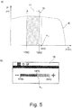
- Fig. 5a is also a performance curve K of an internal combustion engine 8 and a defined speed range 11 shown.
- the upper limit is 1860 1 / min and the lower limit is 1760 1 / min.
- the currently set working speed n A is marked, ie the actual speed specification of the output shaft 9 for the agricultural processing to be carried out. This is here, in particular manually (by the driver), for example, 1910 1 / min ("full throttle") has been reduced to 1870 1 / min.
- the driver wants to reduce the working speed n A is, for example, that the expected power consumption of the work units 5 in the agricultural processing to be performed is less than before and by reducing the operating speed n A fuel consumption and pollutant emissions can be reduced.
- the described automated switching of the internal combustion engine 8 from one of the power stages LS to another of the power stages LS could be effected substantially only at full throttle, but not at any lower operating speeds n A , especially not in semi-gas operation.
- an offset 16 may be provided to the lying within the switching limits speed range 11, which is here for example 10 1 / min.
- the upper limit of the speed range automatically shifts to 1860 1 / min and the lower limit to 1760 1 / min.
- Fig. 5b can be displayed on the display 15, the currently set working speed n A , or directly manually move, as far as it is, for example, a touch panel.
- the speed range 11 or its switching limits thereby automatically move with.
Landscapes
- Life Sciences & Earth Sciences (AREA)
- Environmental Sciences (AREA)
- Engineering & Computer Science (AREA)
- Chemical & Material Sciences (AREA)
- Combustion & Propulsion (AREA)
- Mechanical Engineering (AREA)
- General Engineering & Computer Science (AREA)
- Control Of Vehicle Engines Or Engines For Specific Uses (AREA)
- Combines (AREA)
Claims (10)
- Machine de travail agricole, en particulier machine de récolte, un moteur à combustion interne (8) étant prévu, lequel peut fonctionner à différents niveaux de puissance (LS) dans lesquels il a respectivement une autre courbe caractéristique de puissance (K), au moins un groupe de travail (5) étant prévu, lequel peut être alimenté en puissance (P) fournie par le moteur à combustion interne (8), et un dispositif de régulation (12) étant prévu, lequel est configuré pour provoquer une commutation automatisée du moteur à combustion interne (8) de l'un des niveaux de puissance (LS) à un autre niveau de puissance (LS) dès que les besoins en puissance associés audit au moins un groupe de travail (5) changent,
caractérisée en ce que
les niveaux de puissance (LS) sont associés à différentes plages de niveaux de puissance (BLS) pouvant être présélectionnées, lesquelles diffèrent au moins de par le niveau de puissance (LS) le plus élevé respectivement associé, et en ce que le dispositif de régulation (12) est configuré pour ne provoquer une commutation du moteur à combustion interne (8) qu'entre des niveaux de puissance (LS) de la plage de niveaux de puissance (BLS) respectivement présélectionnée. - Machine de travail agricole selon la revendication 1, caractérisée en ce que le dispositif de régulation (12) permet une présélection manuelle de l'une des plages de niveaux de puissance (BLS) .
- Machine de travail agricole selon la revendication 2, caractérisée en ce que le dispositif de régulation (12) est configuré pour ne provoquer une commutation d'une plage de niveaux de puissance (BLS) plus élevée à une plage de niveaux de puissance (BLS) plus basse que lorsque les besoins en puissance effectifs dudit au moins un groupe de travail (5) sont tombés au-dessous d'une valeur de consigne prédéfinie.
- Machine de travail agricole selon l'une quelconque des revendications précédentes, caractérisée en ce qu'elle comprend un dispositif d'affichage (15) qui est configuré pour présenter à un opérateur (14) les besoins en puissance effectifs dudit au moins un groupe de travail (5).
- Machine de travail agricole selon la revendication 4, caractérisée en ce que le dispositif d'affichage (15) est configuré pour présenter à l'opérateur (14), en particulier conjointement avec les besoins en puissance effectifs dudit au moins un groupe de travail (5), la plage de niveaux de puissance (BLS) présélectionnée et/ou la puissance maximale (Pmax) du niveau de puissance (LS) de la plage de niveaux de puissance (BLS) présélectionnée dans laquelle la puissance maximale (Pmax) est la plus élevée.
- Machine de travail agricole selon l'une quelconque des revendications précédentes, caractérisée en ce que le groupe de travail (5) est sélectionné dans le groupe comportant des groupes de travail (5) entraînés de manière hydraulique et des groupes de travail (5) entraînés de manière rotative, le groupe de travail (5) étant en particulier un outil adaptable (6), par exemple un mécanisme de coupe, de la machine de travail (1).
- Machine de travail agricole selon l'une quelconque des revendications précédentes, caractérisée en ce que le dispositif de régulation (12) est configuré pour ne provoquer une commutation automatisée du moteur à combustion interne (8) entre des niveaux de puissance (LS), en particulier entre des niveaux de puissance (LS) de la plage de niveaux de puissance (BLS) présélectionnée, que lorsque le moteur à combustion interne (8) fonctionne dans une plage de régimes (11) prédéfinie.
- Machine de travail agricole selon la revendication 7, caractérisée en ce que le dispositif de régulation (12) permet une présélection, en particulier une présélection manuelle, d'une plage de régimes (11) dans laquelle le moteur à combustion interne (8) peut être commuté entre des niveaux de puissance (LS), en particulier entre des niveaux de puissance (LS) de la plage de niveaux de puissance (BLS) présélectionnée.
- Machine de travail agricole selon l'une quelconque des revendications précédentes, caractérisée en ce qu'elle comprend un système d'entraînement (7) qui peut être alimenté en puissance (P) fournie par le moteur à combustion interne (8), le moteur à combustion interne (8) pouvant être régulé de telle sorte que, lors de la commutation du moteur à combustion interne (8) de l'un des niveaux de puissance (LS) à un autre niveau de puissance (LS), le régime du système d'entraînement (7) demeure sensiblement constant.
- Procédé de fonctionnement d'une machine de travail agricole, en particulier d'une machine de travail agricole (1) selon l'une quelconque des revendications précédentes, procédé selon lequel un moteur à combustion interne (8) qui peut fonctionner à différents niveaux de puissance (LS) dans lesquels il a respectivement une autre courbe caractéristique de puissance (K) peut être commuté automatiquement de l'un des niveaux de puissance (LS) à un autre niveau de puissance (LS) dès que les besoins en puissance associés audit au moins un groupe de travail (5) changent,
caractérisé en ce que
les niveaux de puissance (LS) sont associés à différentes plages de niveaux de puissance (BLS) pouvant être présélectionnées, lesquelles diffèrent au moins de par le niveau de puissance (LS) le plus élevé respectivement associé, et en ce que le moteur à combustion interne (8) n'est commuté qu'entre des niveaux de puissance (LS) de la plage de niveaux de puissance (BLS) présélectionnée.
Applications Claiming Priority (1)
| Application Number | Priority Date | Filing Date | Title |
|---|---|---|---|
| DE102016111662.9A DE102016111662A1 (de) | 2016-06-24 | 2016-06-24 | Landwirtschaftliche Arbeitsmaschine und Verfahren zum Betrieb einer landwirtschaftlichen Arbeitsmaschine |
Publications (2)
| Publication Number | Publication Date |
|---|---|
| EP3259975A1 EP3259975A1 (fr) | 2017-12-27 |
| EP3259975B1 true EP3259975B1 (fr) | 2019-04-10 |
Family
ID=58108537
Family Applications (1)
| Application Number | Title | Priority Date | Filing Date |
|---|---|---|---|
| EP17157431.2A Active EP3259975B1 (fr) | 2016-06-24 | 2017-02-22 | Engin agricole et procédé de fonctionnement d'un engin agricole |
Country Status (4)
| Country | Link |
|---|---|
| US (1) | US10119483B2 (fr) |
| EP (1) | EP3259975B1 (fr) |
| DE (1) | DE102016111662A1 (fr) |
| RU (1) | RU2734489C2 (fr) |
Families Citing this family (7)
| Publication number | Priority date | Publication date | Assignee | Title |
|---|---|---|---|---|
| DE102019206829A1 (de) * | 2019-05-10 | 2020-11-12 | Deere & Company | Antriebssystem für eine Erntemaschine |
| DE102019135214A1 (de) | 2019-12-19 | 2021-06-24 | Claas Selbstfahrende Erntemaschinen Gmbh | Verfahren zum Antreiben |
| US11439064B2 (en) * | 2020-08-04 | 2022-09-13 | Deere & Company | Pre-unloading power reduction system and method |
| JP7145418B2 (ja) * | 2020-08-27 | 2022-10-03 | 井関農機株式会社 | コンバイン |
| CN114715118A (zh) * | 2022-04-21 | 2022-07-08 | 潍柴雷沃重工股份有限公司 | 用于农用机械的节能降耗方法、系统、介质、设备及农机 |
| DE102022113276A1 (de) * | 2022-05-25 | 2023-11-30 | Usines Claas France S.A.S | Landwirtschaftliche Ballenpresse mit einer Spanneinrichtung für einen Zugmitteltrieb |
| US12247525B2 (en) * | 2022-11-09 | 2025-03-11 | Deere & Company | Management of power transition for driver assistance |
Family Cites Families (9)
| Publication number | Priority date | Publication date | Assignee | Title |
|---|---|---|---|---|
| US7373239B2 (en) * | 2005-07-06 | 2008-05-13 | Komatsu, Ltd. | Engine control device of work vehicle |
| DE102006006766A1 (de) * | 2006-02-13 | 2007-08-23 | Claas Selbstfahrende Erntemaschinen Gmbh | Motorfahrzeug |
| DE102008020497A1 (de) | 2008-04-23 | 2009-11-05 | Claas Selbstfahrende Erntemaschinen Gmbh | Betriebsverfahren für einen Verbrennungsmotor |
| DE102008036378A1 (de) * | 2008-08-05 | 2010-02-11 | Claas Selbstfahrende Erntemaschinen Gmbh | Landwirtschaftliche Erntemaschine |
| US8087900B2 (en) * | 2009-05-22 | 2012-01-03 | Deere & Company | Agricultural harvester with propulsion load shifting between dual engines |
| JP5044727B2 (ja) * | 2010-05-17 | 2012-10-10 | 株式会社小松製作所 | 油圧ショベル及び油圧ショベルの制御方法 |
| DE102012016445B3 (de) * | 2012-08-18 | 2013-05-29 | Abg Allgemeine Baumaschinen-Gesellschaft Mbh | Verfahren zum Einstellen der Drehzahl eines Verbrennungsmotors einer Straßenbaumaschine und Straßenbaumaschine hierfür |
| CN104995386B (zh) * | 2013-03-06 | 2017-09-26 | 日立建机株式会社 | 工程机械 |
| DE102013108208A1 (de) * | 2013-07-31 | 2015-02-05 | Claas Selbstfahrende Erntemaschinen Gmbh | Selbstfahrende Erntemaschine |
-
2016
- 2016-06-24 DE DE102016111662.9A patent/DE102016111662A1/de not_active Withdrawn
-
2017
- 2017-02-22 EP EP17157431.2A patent/EP3259975B1/fr active Active
- 2017-05-31 US US15/609,692 patent/US10119483B2/en active Active
- 2017-06-21 RU RU2017121813A patent/RU2734489C2/ru active
Non-Patent Citations (1)
| Title |
|---|
| None * |
Also Published As
| Publication number | Publication date |
|---|---|
| US20170370303A1 (en) | 2017-12-28 |
| DE102016111662A1 (de) | 2017-12-28 |
| RU2017121813A3 (fr) | 2020-08-24 |
| RU2734489C2 (ru) | 2020-10-19 |
| RU2017121813A (ru) | 2018-12-21 |
| US10119483B2 (en) | 2018-11-06 |
| EP3259975A1 (fr) | 2017-12-27 |
Similar Documents
| Publication | Publication Date | Title |
|---|---|---|
| EP3259976B1 (fr) | Engin agricole et procédé de fonctionnement d'un engin agricole | |
| EP3259975A1 (fr) | Engin agricole et procédé de fonctionnement d'un engin agricole | |
| EP2987396B1 (fr) | Systeme d'assistance du conducteur pour engin agricole | |
| EP2936969B1 (fr) | Combinaison d'un véhicule de traction et d'une moissonneuse tirée par celui-ci | |
| EP2223588B1 (fr) | Récolteuse automobile | |
| EP3401195B1 (fr) | Machine agricole | |
| DE10134137B4 (de) | Selbstfahrende landwirtschaftliche Erntemaschine | |
| DE102007055074A1 (de) | Selbstfahrende landwirtschaftliche Arbeitsmaschine | |
| EP3326446B1 (fr) | Dispositif de commande de vitesse d'une moissonneuse | |
| EP1419687B1 (fr) | Procédé pour contrôler la vitesse d'une machine de récolte | |
| EP4056008A1 (fr) | Agencement de machine agricole | |
| DE60320489T2 (de) | Arbeitsfahrzeug mit einer Vorrichtung zum Einstellen der Anlaufstromversorgung einer proportionalen Variatorsteuerung | |
| EP3257353B1 (fr) | Machine agricole et procede de fonctionnement d'une machine agricole | |
| DE102007018321A1 (de) | Erntemaschine | |
| EP2329981B1 (fr) | Agencement d'entraînement et procédé pour une machine de travail dotée de deux moteurs à combustion | |
| DE102008020497A1 (de) | Betriebsverfahren für einen Verbrennungsmotor | |
| EP3461313A1 (fr) | Engin agricole | |
| EP3760027B1 (fr) | Système d'entraînement pour une machine de récolte | |
| EP3777499A1 (fr) | Tracteur agricole | |
| EP3400797A1 (fr) | Engin agricole | |
| EP3300584B1 (fr) | Engin agricole et procédé de fonctionnement d'un engin agricole | |
| DE102017214097A1 (de) | Antriebssystem für einen Erntevorsatz einer Erntemaschine mit selbsttätiger Abschaltung bei Überlast | |
| EP3348135B1 (fr) | Système d'entraînement pour une tête de récolte d'une machine de récolte à arrêt automatique lors de surcharge | |
| EP1236389A1 (fr) | Machine agricole de récolte automotrice avec un dispositif pour ajuster la vitesse de travaille du moteur | |
| EP3906773B1 (fr) | Machine de travail agricole comprenant un engin hybride et un accumulateur d'énergie, l'état de charge de l'accumulateur d'énergie étant controlé sur la base d'un pronostic de la charge de travail attendue |
Legal Events
| Date | Code | Title | Description |
|---|---|---|---|
| PUAI | Public reference made under article 153(3) epc to a published international application that has entered the european phase |
Free format text: ORIGINAL CODE: 0009012 |
|
| STAA | Information on the status of an ep patent application or granted ep patent |
Free format text: STATUS: THE APPLICATION HAS BEEN PUBLISHED |
|
| AK | Designated contracting states |
Kind code of ref document: A1 Designated state(s): AL AT BE BG CH CY CZ DE DK EE ES FI FR GB GR HR HU IE IS IT LI LT LU LV MC MK MT NL NO PL PT RO RS SE SI SK SM TR |
|
| AX | Request for extension of the european patent |
Extension state: BA ME |
|
| STAA | Information on the status of an ep patent application or granted ep patent |
Free format text: STATUS: REQUEST FOR EXAMINATION WAS MADE |
|
| 17P | Request for examination filed |
Effective date: 20180627 |
|
| RBV | Designated contracting states (corrected) |
Designated state(s): AL AT BE BG CH CY CZ DE DK EE ES FI FR GB GR HR HU IE IS IT LI LT LU LV MC MK MT NL NO PL PT RO RS SE SI SK SM TR |
|
| GRAP | Despatch of communication of intention to grant a patent |
Free format text: ORIGINAL CODE: EPIDOSNIGR1 |
|
| RIC1 | Information provided on ipc code assigned before grant |
Ipc: A01D 43/08 20060101AFI20181016BHEP Ipc: F02D 29/02 20060101ALI20181016BHEP Ipc: A01D 41/127 20060101ALI20181016BHEP Ipc: A01B 67/00 20060101ALI20181016BHEP |
|
| STAA | Information on the status of an ep patent application or granted ep patent |
Free format text: STATUS: GRANT OF PATENT IS INTENDED |
|
| INTG | Intention to grant announced |
Effective date: 20181122 |
|
| GRAS | Grant fee paid |
Free format text: ORIGINAL CODE: EPIDOSNIGR3 |
|
| GRAA | (expected) grant |
Free format text: ORIGINAL CODE: 0009210 |
|
| STAA | Information on the status of an ep patent application or granted ep patent |
Free format text: STATUS: THE PATENT HAS BEEN GRANTED |
|
| AK | Designated contracting states |
Kind code of ref document: B1 Designated state(s): AL AT BE BG CH CY CZ DE DK EE ES FI FR GB GR HR HU IE IS IT LI LT LU LV MC MK MT NL NO PL PT RO RS SE SI SK SM TR |
|
| REG | Reference to a national code |
Ref country code: GB Ref legal event code: FG4D Free format text: NOT ENGLISH |
|
| REG | Reference to a national code |
Ref country code: CH Ref legal event code: EP Ref country code: AT Ref legal event code: REF Ref document number: 1117405 Country of ref document: AT Kind code of ref document: T Effective date: 20190415 |
|
| REG | Reference to a national code |
Ref country code: DE Ref legal event code: R096 Ref document number: 502017001062 Country of ref document: DE |
|
| REG | Reference to a national code |
Ref country code: IE Ref legal event code: FG4D Free format text: LANGUAGE OF EP DOCUMENT: GERMAN |
|
| REG | Reference to a national code |
Ref country code: NL Ref legal event code: MP Effective date: 20190410 |
|
| REG | Reference to a national code |
Ref country code: LT Ref legal event code: MG4D |
|
| PG25 | Lapsed in a contracting state [announced via postgrant information from national office to epo] |
Ref country code: NL Free format text: LAPSE BECAUSE OF FAILURE TO SUBMIT A TRANSLATION OF THE DESCRIPTION OR TO PAY THE FEE WITHIN THE PRESCRIBED TIME-LIMIT Effective date: 20190410 |
|
| PG25 | Lapsed in a contracting state [announced via postgrant information from national office to epo] |
Ref country code: LT Free format text: LAPSE BECAUSE OF FAILURE TO SUBMIT A TRANSLATION OF THE DESCRIPTION OR TO PAY THE FEE WITHIN THE PRESCRIBED TIME-LIMIT Effective date: 20190410 Ref country code: PT Free format text: LAPSE BECAUSE OF FAILURE TO SUBMIT A TRANSLATION OF THE DESCRIPTION OR TO PAY THE FEE WITHIN THE PRESCRIBED TIME-LIMIT Effective date: 20190910 Ref country code: NO Free format text: LAPSE BECAUSE OF FAILURE TO SUBMIT A TRANSLATION OF THE DESCRIPTION OR TO PAY THE FEE WITHIN THE PRESCRIBED TIME-LIMIT Effective date: 20190710 Ref country code: FI Free format text: LAPSE BECAUSE OF FAILURE TO SUBMIT A TRANSLATION OF THE DESCRIPTION OR TO PAY THE FEE WITHIN THE PRESCRIBED TIME-LIMIT Effective date: 20190410 Ref country code: SE Free format text: LAPSE BECAUSE OF FAILURE TO SUBMIT A TRANSLATION OF THE DESCRIPTION OR TO PAY THE FEE WITHIN THE PRESCRIBED TIME-LIMIT Effective date: 20190410 Ref country code: HR Free format text: LAPSE BECAUSE OF FAILURE TO SUBMIT A TRANSLATION OF THE DESCRIPTION OR TO PAY THE FEE WITHIN THE PRESCRIBED TIME-LIMIT Effective date: 20190410 Ref country code: ES Free format text: LAPSE BECAUSE OF FAILURE TO SUBMIT A TRANSLATION OF THE DESCRIPTION OR TO PAY THE FEE WITHIN THE PRESCRIBED TIME-LIMIT Effective date: 20190410 Ref country code: AL Free format text: LAPSE BECAUSE OF FAILURE TO SUBMIT A TRANSLATION OF THE DESCRIPTION OR TO PAY THE FEE WITHIN THE PRESCRIBED TIME-LIMIT Effective date: 20190410 |
|
| PG25 | Lapsed in a contracting state [announced via postgrant information from national office to epo] |
Ref country code: GR Free format text: LAPSE BECAUSE OF FAILURE TO SUBMIT A TRANSLATION OF THE DESCRIPTION OR TO PAY THE FEE WITHIN THE PRESCRIBED TIME-LIMIT Effective date: 20190711 Ref country code: BG Free format text: LAPSE BECAUSE OF FAILURE TO SUBMIT A TRANSLATION OF THE DESCRIPTION OR TO PAY THE FEE WITHIN THE PRESCRIBED TIME-LIMIT Effective date: 20190710 Ref country code: RS Free format text: LAPSE BECAUSE OF FAILURE TO SUBMIT A TRANSLATION OF THE DESCRIPTION OR TO PAY THE FEE WITHIN THE PRESCRIBED TIME-LIMIT Effective date: 20190410 Ref country code: LV Free format text: LAPSE BECAUSE OF FAILURE TO SUBMIT A TRANSLATION OF THE DESCRIPTION OR TO PAY THE FEE WITHIN THE PRESCRIBED TIME-LIMIT Effective date: 20190410 Ref country code: PL Free format text: LAPSE BECAUSE OF FAILURE TO SUBMIT A TRANSLATION OF THE DESCRIPTION OR TO PAY THE FEE WITHIN THE PRESCRIBED TIME-LIMIT Effective date: 20190410 |
|
| PG25 | Lapsed in a contracting state [announced via postgrant information from national office to epo] |
Ref country code: IS Free format text: LAPSE BECAUSE OF FAILURE TO SUBMIT A TRANSLATION OF THE DESCRIPTION OR TO PAY THE FEE WITHIN THE PRESCRIBED TIME-LIMIT Effective date: 20190810 |
|
| REG | Reference to a national code |
Ref country code: DE Ref legal event code: R097 Ref document number: 502017001062 Country of ref document: DE |
|
| PG25 | Lapsed in a contracting state [announced via postgrant information from national office to epo] |
Ref country code: EE Free format text: LAPSE BECAUSE OF FAILURE TO SUBMIT A TRANSLATION OF THE DESCRIPTION OR TO PAY THE FEE WITHIN THE PRESCRIBED TIME-LIMIT Effective date: 20190410 Ref country code: DK Free format text: LAPSE BECAUSE OF FAILURE TO SUBMIT A TRANSLATION OF THE DESCRIPTION OR TO PAY THE FEE WITHIN THE PRESCRIBED TIME-LIMIT Effective date: 20190410 Ref country code: SK Free format text: LAPSE BECAUSE OF FAILURE TO SUBMIT A TRANSLATION OF THE DESCRIPTION OR TO PAY THE FEE WITHIN THE PRESCRIBED TIME-LIMIT Effective date: 20190410 Ref country code: CZ Free format text: LAPSE BECAUSE OF FAILURE TO SUBMIT A TRANSLATION OF THE DESCRIPTION OR TO PAY THE FEE WITHIN THE PRESCRIBED TIME-LIMIT Effective date: 20190410 Ref country code: RO Free format text: LAPSE BECAUSE OF FAILURE TO SUBMIT A TRANSLATION OF THE DESCRIPTION OR TO PAY THE FEE WITHIN THE PRESCRIBED TIME-LIMIT Effective date: 20190410 |
|
| PLBE | No opposition filed within time limit |
Free format text: ORIGINAL CODE: 0009261 |
|
| STAA | Information on the status of an ep patent application or granted ep patent |
Free format text: STATUS: NO OPPOSITION FILED WITHIN TIME LIMIT |
|
| PG25 | Lapsed in a contracting state [announced via postgrant information from national office to epo] |
Ref country code: SM Free format text: LAPSE BECAUSE OF FAILURE TO SUBMIT A TRANSLATION OF THE DESCRIPTION OR TO PAY THE FEE WITHIN THE PRESCRIBED TIME-LIMIT Effective date: 20190410 Ref country code: IT Free format text: LAPSE BECAUSE OF FAILURE TO SUBMIT A TRANSLATION OF THE DESCRIPTION OR TO PAY THE FEE WITHIN THE PRESCRIBED TIME-LIMIT Effective date: 20190410 |
|
| 26N | No opposition filed |
Effective date: 20200113 |
|
| PG25 | Lapsed in a contracting state [announced via postgrant information from national office to epo] |
Ref country code: TR Free format text: LAPSE BECAUSE OF FAILURE TO SUBMIT A TRANSLATION OF THE DESCRIPTION OR TO PAY THE FEE WITHIN THE PRESCRIBED TIME-LIMIT Effective date: 20190410 |
|
| PG25 | Lapsed in a contracting state [announced via postgrant information from national office to epo] |
Ref country code: SI Free format text: LAPSE BECAUSE OF FAILURE TO SUBMIT A TRANSLATION OF THE DESCRIPTION OR TO PAY THE FEE WITHIN THE PRESCRIBED TIME-LIMIT Effective date: 20190410 |
|
| REG | Reference to a national code |
Ref country code: CH Ref legal event code: PL |
|
| PG25 | Lapsed in a contracting state [announced via postgrant information from national office to epo] |
Ref country code: LU Free format text: LAPSE BECAUSE OF NON-PAYMENT OF DUE FEES Effective date: 20200222 Ref country code: MC Free format text: LAPSE BECAUSE OF FAILURE TO SUBMIT A TRANSLATION OF THE DESCRIPTION OR TO PAY THE FEE WITHIN THE PRESCRIBED TIME-LIMIT Effective date: 20190410 |
|
| PG25 | Lapsed in a contracting state [announced via postgrant information from national office to epo] |
Ref country code: LI Free format text: LAPSE BECAUSE OF NON-PAYMENT OF DUE FEES Effective date: 20200229 Ref country code: CH Free format text: LAPSE BECAUSE OF NON-PAYMENT OF DUE FEES Effective date: 20200229 |
|
| PG25 | Lapsed in a contracting state [announced via postgrant information from national office to epo] |
Ref country code: FR Free format text: LAPSE BECAUSE OF NON-PAYMENT OF DUE FEES Effective date: 20200229 Ref country code: IE Free format text: LAPSE BECAUSE OF NON-PAYMENT OF DUE FEES Effective date: 20200222 |
|
| GBPC | Gb: european patent ceased through non-payment of renewal fee |
Effective date: 20210222 |
|
| PG25 | Lapsed in a contracting state [announced via postgrant information from national office to epo] |
Ref country code: GB Free format text: LAPSE BECAUSE OF NON-PAYMENT OF DUE FEES Effective date: 20210222 |
|
| PG25 | Lapsed in a contracting state [announced via postgrant information from national office to epo] |
Ref country code: MT Free format text: LAPSE BECAUSE OF FAILURE TO SUBMIT A TRANSLATION OF THE DESCRIPTION OR TO PAY THE FEE WITHIN THE PRESCRIBED TIME-LIMIT Effective date: 20190410 Ref country code: CY Free format text: LAPSE BECAUSE OF FAILURE TO SUBMIT A TRANSLATION OF THE DESCRIPTION OR TO PAY THE FEE WITHIN THE PRESCRIBED TIME-LIMIT Effective date: 20190410 |
|
| PG25 | Lapsed in a contracting state [announced via postgrant information from national office to epo] |
Ref country code: MK Free format text: LAPSE BECAUSE OF FAILURE TO SUBMIT A TRANSLATION OF THE DESCRIPTION OR TO PAY THE FEE WITHIN THE PRESCRIBED TIME-LIMIT Effective date: 20190410 |
|
| REG | Reference to a national code |
Ref country code: AT Ref legal event code: MM01 Ref document number: 1117405 Country of ref document: AT Kind code of ref document: T Effective date: 20220222 |
|
| PG25 | Lapsed in a contracting state [announced via postgrant information from national office to epo] |
Ref country code: AT Free format text: LAPSE BECAUSE OF NON-PAYMENT OF DUE FEES Effective date: 20220222 |
|
| P01 | Opt-out of the competence of the unified patent court (upc) registered |
Effective date: 20230516 |
|
| PGFP | Annual fee paid to national office [announced via postgrant information from national office to epo] |
Ref country code: DE Payment date: 20260218 Year of fee payment: 10 |
|
| PGFP | Annual fee paid to national office [announced via postgrant information from national office to epo] |
Ref country code: BE Payment date: 20260218 Year of fee payment: 10 |