EP3260221A1 - Chambre de moulage horizontale, kit comprenant une chambre de moulage et une aide au remplissage et procédé de moulage par pression de métal dans une chambre de moulage - Google Patents
Chambre de moulage horizontale, kit comprenant une chambre de moulage et une aide au remplissage et procédé de moulage par pression de métal dans une chambre de moulage Download PDFInfo
- Publication number
- EP3260221A1 EP3260221A1 EP17175112.6A EP17175112A EP3260221A1 EP 3260221 A1 EP3260221 A1 EP 3260221A1 EP 17175112 A EP17175112 A EP 17175112A EP 3260221 A1 EP3260221 A1 EP 3260221A1
- Authority
- EP
- European Patent Office
- Prior art keywords
- casting chamber
- casting
- base body
- gussmaterialeinfüllöffnung
- funnel
- Prior art date
- Legal status (The legal status is an assumption and is not a legal conclusion. Google has not performed a legal analysis and makes no representation as to the accuracy of the status listed.)
- Withdrawn
Links
- 238000005266 casting Methods 0.000 title claims abstract description 102
- 238000000034 method Methods 0.000 title claims abstract description 9
- 238000005058 metal casting Methods 0.000 title abstract description 3
- 238000004512 die casting Methods 0.000 claims abstract description 15
- 229910052751 metal Inorganic materials 0.000 claims abstract description 8
- 239000002184 metal Substances 0.000 claims abstract description 8
- 239000000463 material Substances 0.000 claims description 41
- 230000007935 neutral effect Effects 0.000 claims description 7
- 239000002826 coolant Substances 0.000 claims description 4
- 238000005496 tempering Methods 0.000 claims description 4
- 230000007704 transition Effects 0.000 claims description 4
- 230000007423 decrease Effects 0.000 claims description 2
- 239000000919 ceramic Substances 0.000 description 6
- 238000006073 displacement reaction Methods 0.000 description 2
- 238000002386 leaching Methods 0.000 description 2
- 230000035882 stress Effects 0.000 description 2
- 230000008646 thermal stress Effects 0.000 description 2
- 229910001369 Brass Inorganic materials 0.000 description 1
- XEEYBQQBJWHFJM-UHFFFAOYSA-N Iron Chemical group [Fe] XEEYBQQBJWHFJM-UHFFFAOYSA-N 0.000 description 1
- FYYHWMGAXLPEAU-UHFFFAOYSA-N Magnesium Chemical compound [Mg] FYYHWMGAXLPEAU-UHFFFAOYSA-N 0.000 description 1
- 229910052782 aluminium Inorganic materials 0.000 description 1
- XAGFODPZIPBFFR-UHFFFAOYSA-N aluminium Chemical compound [Al] XAGFODPZIPBFFR-UHFFFAOYSA-N 0.000 description 1
- 230000015572 biosynthetic process Effects 0.000 description 1
- 239000010951 brass Substances 0.000 description 1
- 238000001816 cooling Methods 0.000 description 1
- 230000003111 delayed effect Effects 0.000 description 1
- 238000005429 filling process Methods 0.000 description 1
- 230000005484 gravity Effects 0.000 description 1
- 229910052749 magnesium Inorganic materials 0.000 description 1
- 239000011777 magnesium Substances 0.000 description 1
- 229910001092 metal group alloy Inorganic materials 0.000 description 1
- 239000007769 metal material Substances 0.000 description 1
- 150000002739 metals Chemical class 0.000 description 1
- 238000009991 scouring Methods 0.000 description 1
Images


Classifications
-
- B—PERFORMING OPERATIONS; TRANSPORTING
- B22—CASTING; POWDER METALLURGY
- B22D—CASTING OF METALS; CASTING OF OTHER SUBSTANCES BY THE SAME PROCESSES OR DEVICES
- B22D17/00—Pressure die casting or injection die casting, i.e. casting in which the metal is forced into a mould under high pressure
- B22D17/08—Cold chamber machines, i.e. with unheated press chamber into which molten metal is ladled
- B22D17/10—Cold chamber machines, i.e. with unheated press chamber into which molten metal is ladled with horizontal press motion
-
- B—PERFORMING OPERATIONS; TRANSPORTING
- B22—CASTING; POWDER METALLURGY
- B22D—CASTING OF METALS; CASTING OF OTHER SUBSTANCES BY THE SAME PROCESSES OR DEVICES
- B22D17/00—Pressure die casting or injection die casting, i.e. casting in which the metal is forced into a mould under high pressure
- B22D17/20—Accessories: Details
- B22D17/2015—Means for forcing the molten metal into the die
- B22D17/2023—Nozzles or shot sleeves
Definitions
- Casting chambers are primarily used in die casting machines for die casting metals such as aluminum, magnesium and brass.
- horizontal casting chambers are used, which are used horizontally in operation and whose shell body has at its one, machine-side end at the top of a Gussmaterialein colllö réelle and at its other, form-side end a central, axial Gussmaterialauslassö réelle.
- the casting chambers are exposed to high thermal and mechanical loads.
- the Gußmaterialein colllötician reaches temperatures of significantly more than 600 ° C.
- iron atoms may diffuse out of the surface of the casting chamber, causing it to become brittle and flake off, causing scouring, which may impede the sliding movement of a pressure piston in the casting chamber and expose the pressure piston to increased wear.
- hot casting material filled in by the pouring material filling opening always makes use of the gravitational force to strike its inner surface in the respectively underlying area of the interior of the exchangeable bushing.
- the invention is therefore an object of the invention to provide a horizontal casting chamber and a method for die casting of metal in such a horizontal casting chamber, by which it is possible to increase the life of the horizontal casting chamber.
- this object is achieved in that fastening means or fastening means and positioning means are provided, by means of which the removable bushing can be positioned and secured in a plurality of defined, about the central axis against each other twisted mounting positions on the body.
- the invention is achieved in a method for die casting of metal of the type mentioned in that the exchange bushing detached from the body, relative to this rotated about the central axis in a new mounting position and in this again fluid-tightly and releasably connected to the body becomes.
- the invention is thus based on the consideration, the casting chamber in such a way that the removable sleeve can be mounted in different angular positions on the body.
- the change bushing can be solved in a simple manner from the base body, rotated about the central axis in a different mounting position and in this again attached to the base body. In the new mounting position, the bottom area of the exchangeable sleeve then lying down is not or only slightly washed out.
- the exchangeable sleeve can be brought into different fastening positions relative to the main body, in which case at least different regions of the inner surface of the exchangeable sleeve form the bottom region thereof, which is hit by the hot casting material filled through the casting material filling opening.
- the replacement intervals for the exchangeable bushing and / or a wear bushing located in the replaceable bush are lengthened.
- the exchangeable sleeve of the horizontal casting chamber according to the invention can be positioned and fixed in a neutral position on the base body such that the Gussmaterialein colllö réelle is located at the top of the casting chamber and in particular is vertically aligned, wherein the exchangeable sleeve is preferably positionable and fixable in two further attachment positions on the base body, which are rotated relative to the neutral position in a clockwise and counterclockwise direction, so that the Gussmaterialein spallö founded in each of these two attachment positions obliquely upwards.
- the hot casting material can be filled particularly conveniently into the casting chamber by utilizing the force of gravity.
- the attachment positions are offset by equal angles to each other, wherein the angle between two adjacent attachment positions is in particular between 30 ° and 60 °, and preferably 45 °.
- Such an angular offset is particularly advantageous when a mounting position is defined in which the Gussmaterialein colllö Anlagen is vertically aligned. Because in another mounting position, which is adjacent to the aforementioned and offset by an angle of 45 °, such an angle ensures that hot casting material can easily flow into the casting chamber by utilizing the gravitational force.
- an angle of 45 ° is large enough so that the places where the casting material impinges on the inner surface, far enough from each other lie away and thus the most uniform possible stress on the inner surface is ensured.
- the exchangeable sleeve and the base body are screwed together and positioned by the screw in the different mounting positions.
- through holes are provided in the replaceable bushing, which pass through the exchangeable bushing axially between their end faces, and are formed in the end face of the body to the through holes corresponding threaded holes through which the replaceable bushing and the main body can be screwed by means of fastening screws in the different mounting positions.
- the threaded holes are preferably blind holes.
- the through bores and / or the threaded holes can be arranged with uniform offset along the circumference of the jacket body, wherein in the region of Gussmaterialein colllö réelle no through hole is present and wherein the angular offset between the through holes in particular between 30 ° and 60 ° and is preferably 45 °.
- a uniform offset of the holes allows each two adjacent, defined mounting positions are rotated by the same angle to each other. Therefore, it makes sense not to provide a through hole in the region of the Gussmaterialein spallö réelle because such and / or possibly inserted into this fastening screw would hinder the pouring of the casting material in the casting chamber.
- At least one inlet and at least one outlet of a tempering system is formed on the base body, in particular in the immediate vicinity of a transition region between the base body and the exchangeable sleeve, wherein the inlets and outlets extend in particular in a radial direction of the shell body and with at least one in the wall of the jacket body extending coolant channel are fluidly connected. Since during operation of a casting chamber different areas thereof are heated to different degrees by the hot casting material, the temperature in the casting chamber can be adjusted and kept constant by means of a tempering system. By cooling a region below or opposite the Gussmaterialein colllö Anlagen Eisen embrittled the material of the casting less and leaching is counteracted or their formation is delayed.
- the Gussmaterialein spallötician is funnel-shaped, with its cross-section decreases towards the interior of the sheath body out. This facilitates the filling of the casting material.
- the sheath body substantially in the form of a hollow cylinder, in particular wherein the inner diameter is about 120 mm and / or its outer diameter is about 280 to 360 mm and / or the total length is about 815 mm and / or the length of the interchangeable bushing about 320 mm is.
- a filling aid is preferably inserted into the casting material filling opening.
- the filling aid may be a funnel, which is preferably designed in such a way that the funnel inlet opening points vertically upwards when the funnel is inserted into a casting material filling opening of the exchangeable bushing pointing only obliquely upwards.
- the outer contour of the funnel is preferred to the The contour of the pouring material filling opening is adjusted so that the funnel completely closes the pouring material filling opening.
- a casting chamber which has an increased service life compared to the previously known horizontal casting chambers.
- the method described above makes it possible to significantly increase the service life of a horizontal casting chamber.
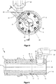
- FIGS. 1 to 5 show different views of a horizontal casting chamber 1 according to the invention for the die casting of metal according to an embodiment of the present invention.
- the casting chamber 1 has an elongated, a central axis A defining shell body 2.
- this has substantially the shape of a hollow cylinder, in which case the inner diameter is about 120 mm, the outer diameter is in large parts about 280 mm and whose total length is about 815 mm.
- the sheath body 2 has at its machine-side end 3 a funnel-shaped Gussmaterialein colllö réelle 4, the cross-section of which reduces towards the interior of the sheath body 2, and at its mold-side end 5 a central, axial Gussmaterialauslassö réelle 6.
- the sheath body 2 is divided along the central axis A in a Gussmaterialauslassö réelle 6 comprehensive body 7 and the Gussmaterialein colllö réelle 4 comprehensive exchange bushing 8, wherein the length of the exchangeable sleeve 8 with about 320 mm is slightly more than a third of the total length of the sheath body 2.
- the main body 7 and the exchangeable sleeve 8 are at their to each other assigning ends 9, 10 fluid-tight and releasably connected to each other.
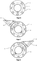
- fastening means by means of which the exchangeable sleeve 8 can be positioned and fastened in a plurality of defined, about the central axis A against each other twisted mounting positions on the base body 7, such as in the FIGS. 6 to 8 is shown.
- These show the exchangeable bushing 8 in three different attachment positions on the base body 7.
- the exchange bushing 8 is positioned and fixed in a neutral position on the base body 7 such that the Gussmaterialein spallö réelle 4 is located on the upper side 11 of the casting chamber 1 and is vertically aligned.
- the fastening means comprise seven through holes 12 which pass through the exchangeable sleeve 8 axially between their end faces 13, 14 and with a uniform angular displacement of 45 ° along the circumference of the interchangeable sleeve 8 in the Wall 15 of the shell body 2 are arranged, wherein in the region of the Gussmaterialein colllö réelle 4 a through hole 12 is omitted.
- threaded holes 17 are formed in the form of blind holes, which are arranged with a uniform angular displacement of 45 ° along the circumference of the base body 7 in the wall 15 of the shell body 2 and via which the exchangeable sleeve 8 and the main body 7 by means of fastening screws 18 can be positioned and screwed in the different attachment positions.
- the fastening screws 18 are hexagon socket screws. It is understood that in general any type of screw can be used.
- the base body 7 with eight threaded holes 17 has a threaded bore 17 more than through holes 12 in the removable bushing 8 are present.
- the inlets and outlets 21 extend in a radial direction R of the jacket body 2 and are fluid-connected to a coolant channel extending in the wall 15 of the jacket body 2.
- the coolant channel is in the FIGS. 1 to 5 not shown.
- a hopper filling aid 22 is inserted into the pouring material filling opening 4 to facilitate filling of pouring material into the pouring chamber 1 when the pouring material filling opening 4 is inclined upward.
- the funnel 22 is designed such that its funnel inlet opening 23 always points vertically upwards even when the casting material filling opening 4 points obliquely upwards.
- the outer contour of the funnel 22 is adapted to the shape of the Gussmaterialein colllö réelle 4, so that the funnel 22, the Gußmaterialein spallö réelle 4 completely encloses.
Landscapes
- Engineering & Computer Science (AREA)
- Mechanical Engineering (AREA)
- Molds, Cores, And Manufacturing Methods Thereof (AREA)
Applications Claiming Priority (1)
| Application Number | Priority Date | Filing Date | Title |
|---|---|---|---|
| DE102016111663.7A DE102016111663A1 (de) | 2016-06-24 | 2016-06-24 | Horizontale Gießkammer, Kit mit einer Gießkammer und einer Einfüllhilfe sowie Verfahren zum Druckgießen von Metall in einer Gießkammer |
Publications (1)
| Publication Number | Publication Date |
|---|---|
| EP3260221A1 true EP3260221A1 (fr) | 2017-12-27 |
Family
ID=59034547
Family Applications (1)
| Application Number | Title | Priority Date | Filing Date |
|---|---|---|---|
| EP17175112.6A Withdrawn EP3260221A1 (fr) | 2016-06-24 | 2017-06-08 | Chambre de moulage horizontale, kit comprenant une chambre de moulage et une aide au remplissage et procédé de moulage par pression de métal dans une chambre de moulage |
Country Status (2)
| Country | Link |
|---|---|
| EP (1) | EP3260221A1 (fr) |
| DE (2) | DE102016111663A1 (fr) |
Cited By (2)
| Publication number | Priority date | Publication date | Assignee | Title |
|---|---|---|---|---|
| CN111451472A (zh) * | 2020-04-27 | 2020-07-28 | 宁波勋辉电器有限公司 | 镁合金车用喇叭罩壳的制造方法 |
| CN115945666A (zh) * | 2023-01-05 | 2023-04-11 | 重庆美利信科技股份有限公司 | 一种大尺寸压铸件的压铸模具及压铸方法 |
Citations (6)
| Publication number | Priority date | Publication date | Assignee | Title |
|---|---|---|---|---|
| DE2449428A1 (de) * | 1974-10-17 | 1976-04-29 | Hugo Kunz | Kolbenkammer fuer druckgiessmaschinen |
| DE10205246A1 (de) * | 2002-02-08 | 2003-08-28 | Kunz Konstruktion Und Druckgie | Füllkammer für eine Druckgießmaschine |
| EP1405685A1 (fr) | 2002-09-25 | 2004-04-07 | ORTMANN Druckgiesstechnik GmbH Giesskammern- Giessbehälter Druckgiesswerkzeuge-Formenbau | Chambre de coulée pour la coulée sous pression de métaux |
| DE102004024952A1 (de) * | 2004-05-21 | 2005-12-22 | Bayerische Motoren Werke Ag | Druckgusswerkzeug |
| DE102015107709A1 (de) * | 2014-06-02 | 2015-12-03 | Ksm Castings Group Gmbh | Gießvorrichtung und Druckgussverfahren |
| DE102014009565A1 (de) * | 2014-06-27 | 2015-12-31 | Wieland-Werke Ag | Füllkammer für eine Druckgießmaschine |
Family Cites Families (2)
| Publication number | Priority date | Publication date | Assignee | Title |
|---|---|---|---|---|
| US5529110A (en) * | 1994-07-25 | 1996-06-25 | Nelson Metal Products Corporation | Rotary actuated closed shot die casting |
| DE10205244C1 (de) * | 2002-02-08 | 2003-07-17 | Kunz Susanne | Füllkammer für eine Druckgießmaschine |
-
2016
- 2016-06-24 DE DE102016111663.7A patent/DE102016111663A1/de not_active Ceased
-
2017
- 2017-06-08 EP EP17175112.6A patent/EP3260221A1/fr not_active Withdrawn
- 2017-06-08 DE DE202017007128.2U patent/DE202017007128U1/de not_active Expired - Lifetime
Patent Citations (6)
| Publication number | Priority date | Publication date | Assignee | Title |
|---|---|---|---|---|
| DE2449428A1 (de) * | 1974-10-17 | 1976-04-29 | Hugo Kunz | Kolbenkammer fuer druckgiessmaschinen |
| DE10205246A1 (de) * | 2002-02-08 | 2003-08-28 | Kunz Konstruktion Und Druckgie | Füllkammer für eine Druckgießmaschine |
| EP1405685A1 (fr) | 2002-09-25 | 2004-04-07 | ORTMANN Druckgiesstechnik GmbH Giesskammern- Giessbehälter Druckgiesswerkzeuge-Formenbau | Chambre de coulée pour la coulée sous pression de métaux |
| DE102004024952A1 (de) * | 2004-05-21 | 2005-12-22 | Bayerische Motoren Werke Ag | Druckgusswerkzeug |
| DE102015107709A1 (de) * | 2014-06-02 | 2015-12-03 | Ksm Castings Group Gmbh | Gießvorrichtung und Druckgussverfahren |
| DE102014009565A1 (de) * | 2014-06-27 | 2015-12-31 | Wieland-Werke Ag | Füllkammer für eine Druckgießmaschine |
Cited By (2)
| Publication number | Priority date | Publication date | Assignee | Title |
|---|---|---|---|---|
| CN111451472A (zh) * | 2020-04-27 | 2020-07-28 | 宁波勋辉电器有限公司 | 镁合金车用喇叭罩壳的制造方法 |
| CN115945666A (zh) * | 2023-01-05 | 2023-04-11 | 重庆美利信科技股份有限公司 | 一种大尺寸压铸件的压铸模具及压铸方法 |
Also Published As
| Publication number | Publication date |
|---|---|
| DE102016111663A1 (de) | 2017-12-28 |
| DE202017007128U1 (de) | 2019-08-29 |
Similar Documents
| Publication | Publication Date | Title |
|---|---|---|
| EP2662163B1 (fr) | Elément de coulée sous pression et procédé de fabrication d'un élément de coulée sous pression | |
| EP2091678B1 (fr) | Moule de coulée pour la coulée d'une pièce et utilisation de ce moule de coulée | |
| DE10354456A1 (de) | Heißläuferdüse mit einer Spitze, einem die Spitze umgebenden Teil und einem Positionierteil | |
| EP1431662B1 (fr) | Chambre de combustion de turbine avec système de refroidissement à circuit fermé | |
| DE3629696C2 (fr) | ||
| DE102007014146A1 (de) | Druckgießwerkzeug | |
| EP3260221A1 (fr) | Chambre de moulage horizontale, kit comprenant une chambre de moulage et une aide au remplissage et procédé de moulage par pression de métal dans une chambre de moulage | |
| DE19716702C2 (de) | Metallische Gußformanordnung für einen Hubkolben sowie Hubkolben, insbesondere für Brennkraftmaschinen | |
| CH617610A5 (en) | Horizontal continuous casting machine for metals | |
| EP3388167B1 (fr) | Piston de coulée sous pression | |
| WO2017152904A2 (fr) | Chambre d'injection d'une machine de coulée sous pression à chambre froide pourvue d'un dispositif de refroidissement, et dispositif de refroidissement | |
| DE60016598T2 (de) | Vorrichtung zum horizontalen stranggiessen von metall | |
| EP2962785A2 (fr) | Chambre de remplissage pour une machine de coulee sous pression | |
| EP2436458B1 (fr) | Lingotière de coulée continue | |
| DE19908392C2 (de) | Gießkammer, insbesondere für das Druckgießen von Metallen | |
| EP3470148B1 (fr) | Dispositif de fabrication de pièces coulées métalliques | |
| EP0695603B1 (fr) | Dispositif de serrage à genouillère | |
| EP0987073A1 (fr) | Paroi pour lingotière de coulée continue | |
| DE4203964A1 (de) | Ringmantel fuer eine walze zum kontinuierlichen giessen | |
| DE102015215482A1 (de) | Kühlölring | |
| WO2017016650A1 (fr) | Dispositif de refroidissement pour le refroidissement d'un mandrin à ajustement fretté | |
| DE102004024952B4 (de) | Druckgusswerkzeug | |
| DE102022101985B4 (de) | GIEßKAMMER FÜR DRUCKGIEßVORRICHTUNG UND DRUCKGIEßVORRICHTUNG MIT EINER SOLCHEN GIEßKAMMER | |
| DE102014117021B3 (de) | Gießdüse, Gießrad und Anordnung umfassend ein Gießrad und mindestens eine Gießdüse | |
| DE19944841A1 (de) | Formgebendes Konturteil für den Einsatz in Druckgießwerkzeugen |
Legal Events
| Date | Code | Title | Description |
|---|---|---|---|
| PUAI | Public reference made under article 153(3) epc to a published international application that has entered the european phase |
Free format text: ORIGINAL CODE: 0009012 |
|
| AK | Designated contracting states |
Kind code of ref document: A1 Designated state(s): AL AT BE BG CH CY CZ DE DK EE ES FI FR GB GR HR HU IE IS IT LI LT LU LV MC MK MT NL NO PL PT RO RS SE SI SK SM TR |
|
| AX | Request for extension of the european patent |
Extension state: BA ME |
|
| 17P | Request for examination filed |
Effective date: 20180607 |
|
| RBV | Designated contracting states (corrected) |
Designated state(s): AL AT BE BG CH CY CZ DE DK EE ES FI FR GB GR HR HU IE IS IT LI LT LU LV MC MK MT NL NO PL PT RO RS SE SI SK SM TR |
|
| RIC1 | Information provided on ipc code assigned before grant |
Ipc: B22D 17/10 20060101AFI20180629BHEP Ipc: B22D 17/20 20060101ALI20180629BHEP |
|
| 17Q | First examination report despatched |
Effective date: 20180723 |
|
| GRAP | Despatch of communication of intention to grant a patent |
Free format text: ORIGINAL CODE: EPIDOSNIGR1 |
|
| INTG | Intention to grant announced |
Effective date: 20190408 |
|
| STAA | Information on the status of an ep patent application or granted ep patent |
Free format text: STATUS: THE APPLICATION IS DEEMED TO BE WITHDRAWN |
|
| 18D | Application deemed to be withdrawn |
Effective date: 20190820 |