EP3260231B1 - Greifer und verfahren zum greifen von enden von drähten und drahtschweissmaschine und roboter mit derartigen greifern - Google Patents
Greifer und verfahren zum greifen von enden von drähten und drahtschweissmaschine und roboter mit derartigen greifern Download PDFInfo
- Publication number
- EP3260231B1 EP3260231B1 EP16175331.4A EP16175331A EP3260231B1 EP 3260231 B1 EP3260231 B1 EP 3260231B1 EP 16175331 A EP16175331 A EP 16175331A EP 3260231 B1 EP3260231 B1 EP 3260231B1
- Authority
- EP
- European Patent Office
- Prior art keywords
- gripper
- clamping jaw
- wire
- area
- moved
- Prior art date
- Legal status (The legal status is an assumption and is not a legal conclusion. Google has not performed a legal analysis and makes no representation as to the accuracy of the status listed.)
- Active
Links
Images


Classifications
-
- B—PERFORMING OPERATIONS; TRANSPORTING
- B23—MACHINE TOOLS; METAL-WORKING NOT OTHERWISE PROVIDED FOR
- B23K—SOLDERING OR UNSOLDERING; WELDING; CLADDING OR PLATING BY SOLDERING OR WELDING; CUTTING BY APPLYING HEAT LOCALLY, e.g. FLAME CUTTING; WORKING BY LASER BEAM
- B23K37/00—Auxiliary devices or processes, not specially adapted for a procedure covered by only one of the other main groups of this subclass
- B23K37/04—Auxiliary devices or processes, not specially adapted for a procedure covered by only one of the other main groups of this subclass for holding or positioning work
- B23K37/0426—Fixtures for other work
- B23K37/0435—Clamps
-
- B—PERFORMING OPERATIONS; TRANSPORTING
- B21—MECHANICAL METAL-WORKING WITHOUT ESSENTIALLY REMOVING MATERIAL; PUNCHING METAL
- B21F—WORKING OR PROCESSING OF METAL WIRE
- B21F15/00—Connecting wire to wire or other metallic material or objects; Connecting parts by means of wire
- B21F15/02—Connecting wire to wire or other metallic material or objects; Connecting parts by means of wire wire with wire
- B21F15/06—Connecting wire to wire or other metallic material or objects; Connecting parts by means of wire wire with wire with additional connecting elements or material
- B21F15/08—Connecting wire to wire or other metallic material or objects; Connecting parts by means of wire wire with wire with additional connecting elements or material making use of soldering or welding
-
- B—PERFORMING OPERATIONS; TRANSPORTING
- B25—HAND TOOLS; PORTABLE POWER-DRIVEN TOOLS; MANIPULATORS
- B25J—MANIPULATORS; CHAMBERS PROVIDED WITH MANIPULATION DEVICES
- B25J15/00—Gripping heads and other end effectors
- B25J15/0052—Gripping heads and other end effectors multiple gripper units or multiple end effectors
-
- B—PERFORMING OPERATIONS; TRANSPORTING
- B25—HAND TOOLS; PORTABLE POWER-DRIVEN TOOLS; MANIPULATORS
- B25J—MANIPULATORS; CHAMBERS PROVIDED WITH MANIPULATION DEVICES
- B25J15/00—Gripping heads and other end effectors
- B25J15/02—Gripping heads and other end effectors servo-actuated
- B25J15/0253—Gripping heads and other end effectors servo-actuated comprising parallel grippers
-
- B—PERFORMING OPERATIONS; TRANSPORTING
- B23—MACHINE TOOLS; METAL-WORKING NOT OTHERWISE PROVIDED FOR
- B23K—SOLDERING OR UNSOLDERING; WELDING; CLADDING OR PLATING BY SOLDERING OR WELDING; CUTTING BY APPLYING HEAT LOCALLY, e.g. FLAME CUTTING; WORKING BY LASER BEAM
- B23K2101/00—Articles made by soldering, welding or cutting
- B23K2101/32—Wires
Definitions
- the present invention relates to a gripper for gripping ends of wires and a method for gripping a wire and positioning the end of the wire with a gripper according to the preamble of claims 1 and 19 (see, eg DE 196 81 534 T1 ).
- Reinforcing or reinforcing steel is known from the prior art, which is used as a reinforcement of reinforced concrete components and is cast after the construction in a formwork with concrete. Typical diameters of such reinforcing or reinforcing steel wires are 6, 8, 10, 12, 14, 16, 20, 25, 28, 32 and 40 mm. Reinforcing or reinforcing steel is produced and rolled up in rolling mills.
- the coiled wires are then further processed, for example to produce rebars, welded mesh, reinforcing wire or the like.
- end of a first to be processed reeled steel is connected to the end of a second to be processed, reeled steel before further processing, so that the steel can be processed continuously.
- they are currently positioned by hand in a wire welding machine in desired welding positions. This requires a considerable amount of force, which is greater the larger the diameter of the wires to be welded.
- joining ends of wires by welding is not limited to the welding of reinforcing or reinforcing steel wires. Other wires can be joined together in the same way by welding.
- the document CN 204800628 U discloses a gripper for a robot or a manipulator (handling device) with the features of claim 1, which can be used for gripping steel bars. It is not known that in the document CN 204800628 U disclosed gripper has been used in a wire welding machine and whether the gripper is adapted to take wires and supply the ends of the wires against the rigidity of a wire welding machine.
- the invention therefore proposes the special gripper for gripping ends of wires according to claim 1 and a wire welding machine with such a gripper.
- An inventive gripper therefore has a catching means, which is movable from a first position to a second position, wherein the catching means in the second position limits the area adjacent to the first clamping jaw at least on one side.
- the catching means makes it possible to initially position the gripper roughly opposite the end of a wire to be gripped.
- the gripper can be accurately positioned after catching the wire by means of the catching means relative to the end of the wire, for which the gripper is moved relative to the wire and wherein a force can be exerted on the gripper by the gripper, without the wire from the catching position from slipping out.
- the catching means can be moved by means of a spring from its first to its second position.
- the spring can be a metallic spring, a spring made of rubber or another Elastomer, an air spring or a gas spring. If a metallic spring is used, this can in particular be a helical compression spring.
- catch means is moved by means of a motor from its first to a second position.
- the catching means may be linearly displaceable from its first position to its second position. It is also possible that the catching means can perform a pivoting movement from its first to its second position. Even more complex movements are possible, which is given for example by a backdrop.
- An inventive gripper may have a trigger.
- This trigger may be coupled to the catching means and / or the spring to initiate the movement of the catching means from its first position to its second position.
- the trigger may, for example, block the spring and release it to trigger the movement of the catch in its second position. But it is also possible that the catch is loaded by the spring and blocked by the trigger. By releasing the blockage of the catch is lifted, so that the catch is moved to its second position.
- the trigger of a gripper may protrude into the region adjacent to the first clamping jaw in a non-triggered state and be in a tripped state out of the region adjacent to the first clamping jaw. If the wire is brought into the gripper or, conversely, the gripper is brought to the wire, the wire may strike against the trigger located in the area adjacent to the first clamping jaw. This can trigger the trigger. The catch can then moved to its second position. As a result, the area adjacent to the first clamping jaw is then limited. The limitation of the area is preferably carried out on the side of the area over which the wire has been moved into the gripper or the gripper has been brought to the wire. By the catch the wire in the gripper is not yet fixed, but already roughly positioned. At the same time, the wire is prevented from slipping out of the gripper during corrective movements between the wire and the gripper, which may be necessary for the exact positioning and alignment of the wire in the gripper.
- the second jaw may be movable from the second position to a third position.
- the catching means By means of the second clamping jaw and / or an object connected to the second clamping jaw, the catching means can be moved from the second position into the first position.
- the movement of the catch means to its first position may be coupled to the movement of the second jaw to its third position.
- the catch may be held in the first position by a latch or hook of the trigger.
- the second clamping jaw may be pivotally mounted on a bearing part.
- the bearing part may be linearly displaceable on and / or mounted to the connecting means.
- the gripper may have a fixedly connected to the connecting means backdrop and connected to the second jaw sliding block, wherein the sliding block is arranged movably in the backdrop.
- the sliding block can be attached to the second jaw.
- the gate may have a slot with a first bent portion and a second straight portion adjoining the first portion.
- the second clamping jaw may be in the first position when the sliding block is in a first position at the end remote from the second region end of the first portion of the slot of the slide.
- the second jaw may be in the second position when the sliding block is in a second position at a location of the slot of the gate at the transition from the first to the second area or adjacent to this location.
- the second jaw may be in the third position when the sliding block is in a third position at the end remote from the first region of the second portion of the slot of the slide.
- An inventive gripper may comprise a stop means which is movable between a first position and a second position. With this sling, it may be possible to accurately position the wire in the gripper.
- the stop means in the first position may be a stop for the end of a wire received from the gripper, while in the second position of the stop means, the end of the wire is free of the stop means, so that the end of the wire can be moved.
- a gripper according to the invention may comprise a hood in which the second clamping jaw is housed in its first position. With the hood it is possible the second jaw in her first position against damage, for example due to collisions of the gripper with a wire, a reel or other protect.
- a wire welding machine may comprise at least one robot or a handling device for feeding ends to wires to be welded, wherein the robot or the handling device has at least one gripper according to the invention for gripping ends of the wire.
- the ends D1 of the wires D are aligned and placed against each other, so that results after joining the ends by welding a kink-free transition from one wire D to the other wire D at the joint.
- the positioning of the wires D before the welding is done - to relieve a machine operator - using the gripper G.
- These grippers G grip the wires D near their ends, so that the ends can be brought to a known position for welding and can be aligned in a desired direction.
- the ends of the wires D do not have a predetermined position prior to joining.
- the wires D are delivered in the example on a reel to the welding machine.
- the Ends of the coiled wires are in this case experience close to the rest, coiled wire on.
- the ends must first, before they can be gripped with a gripper G, be manuallyHogbogen by a machine operator and, if necessary with the help of tools from the reeled wire. After bending out, the end of the wire is off the reel in an arbitrary direction.
- One difficulty is to grasp the ends of the coiled wires D with the gripper G so that the ends are fixed in a certain position to the gripper G. Only then can they be transferred by means of the gripper G into a defined position, for example the welding position.
- the grippers G are mounted, for example, on pivoting arms A of robots R or handling devices which make it possible to move the grippers G in different directions in space and to align them in different directions in space.
- the movement of the grippers or the pivot arms or members of the pivot arms can be done manually, manually or manually with power assistance.
- the gripper G can be brought to the end of a first wire to be gripped. If a desired position and orientation of the wire and the gripper is reached to each other, the gripper G takes the wire D, so that it can then be preferably motorized or manually brought with power assistance in the position in which the weld can be made. Likewise, a second wire D to be gripped can be gripped with a second gripper G and the end of this second wire D brought into a welding position.
- the grippers G thus make it possible to bring the ends of the wires to be welded in the desired welding position. This should be done to relieve the operator with the least possible effort, unlike the usual practice, because so far, the ends of the wires are positioned manually with some considerable effort.
- the gripper G Has an unillustrated connection means with which the gripper G can be connected to a robot or a handling device.
- a housing 1 is provided, which is attached directly or indirectly to the connecting means.
- the housing 1 is not in all Fig. 2 to 9 shown.
- a first clamping jaw 2 of the gripper G is mounted, which is immovable relative to the housing 1.
- a second jaw 3 is movable to the housing 1.
- a trigger 4 is movable to the housing 1.
- a catch 5 is movable to the housing 1.
- a stop means 6 of the gripper.
- Firmly connected to the housing 1 is a hood 7. Not all components of the gripper G are in the FIGS. 2 to 10 shown. In some figures, some components of the gripper G are not shown to more clearly illustrate other components.
- the second jaw 3 of the illustrated gripper G is over a jaw arm 31 pivotally mounted on a bearing part 9.
- the bearing part 9 is guided in a linear guide (not shown) in the housing 1 linearly displaceable.
- the linear movement of the bearing part 9 and consequently the second clamping jaw 3 is effected by a drive which is not fully illustrated.
- the drive is at least partially accommodated in the housing 1.
- the drive can be an electric drive, a pneumatic drive or a hydraulic drive.
- the bearing part 9 is formed by a piston rod which is linearly guided in a cylinder (not shown).
- Piston rod 9 and cylinder are parts of a hydraulic drive for moving the second jaw.
- the housing 1 is further at least one link 8 with a slot ( Fig. 9 ) or a groove (other figures, in particular Fig. 7 ) attached.
- the slot or groove has a bent first region 81, which is followed by a straight region 82.
- a sliding block 10 is guided, which is fixedly connected to the clamping jaw arm 31 of the second clamping jaw 3.
- the gripper shown has two scenes 8, one on the top, one on the underside of the gripper G. In each backdrop 8 a sliding block 10 is provided.
- the sliding blocks 10 are moved in the slots or grooves of the scenes 8.
- a movement of the second clamping jaw 3 is controlled. Due to the first, curved portion of each slot or the grooves of the scenes 8, the second jaw 3 moves in a movement of the sliding blocks 10 in the first, curved portion 81 of the slot or the groove of the scenes 8 along a curved path, which is similar to the first region 81 of the gate 8. Due to a movement of the sliding blocks 10 in the second, straight portion 82 of each slot or groove of the gate 8, the second jaw performs a straight motion.
- the first position assumes the second clamping jaw 3 when the sliding block 10 is at the free end of the first area 81 remote from the second area 82.
- the second clamping jaw 3 is then pivoted outwardly and brought from a region adjacent to the first clamping jaw 2.
- the second position has reached the second clamping jaw 3, when the sliding blocks 10 have reached the transition from the first region 81 of the slot or the groove to the second region 82 of the slot or the groove of the link 8.
- the second clamping jaw 3 is then opposite the first clamping jaw 2, which is the first jaw 2 adjacent region between the two clamping jaws 2, 3rd
- the third position has reached the second clamping jaw 3, when the sliding blocks 10 have reached the free end of the second region 82 of each slot or groove facing away from the first region 81. Between the second and the third position, the second jaw 3 performs a linear movement. The second clamping jaw 3 is moved against the first clamping jaw 2, whereby an object, for example a wire D, can be clamped between the two clamping jaws 2, 3.
- an object for example a wire D
- the second jaw 3 In the first position of the second clamping jaw 3, this is accommodated in the hood 7, which extends laterally from the first clamping jaw 2. In the hood 7, the second jaw 3 is protected in its first position from damage, for example due to a collision with a wire D or other.
- the catching means 5 is also guided linearly movable indirectly or directly attached to the housing 1.
- the catching means 5 comprises a rod 51, to which a plate 52 is fastened with screws.
- the rod 51 is guided linearly displaceable in the housing 1.
- On the plate 52 a projection is provided, whose purpose will be explained later.
- the catching means 5 is arranged laterally next to the first clamping jaw 2. It can assume a first position in which it does not protrude beyond the first clamping jaw 2, or only insignificantly, and projects into the region adjacent to the first clamping jaw 2. In a second position, the catching means 5 projects beyond the first clamping jaw 2 and limits the area adjacent to the first clamping jaw 2 laterally.
- the movement of the catching means 5 from the first position to the second position is effected by a spring (not shown). This may be a helical compression spring.
- the movement of the catching means 5 from the second position to the first position is effected by the movement of the second clamping jaw 3 from the second to the third position of the second clamping jaw 2, for which purpose a driver 11 is fastened to the second clamping jaw 3.
- the driver 11 comes with the movement of the second jaw 3 in the third position to rest on the catch 5, whereby this is moved in a further movement of the second jaw 3 and the driver 11 against the pressure of the coil spring in the first position.
- the trigger 4 is a rod which is pivotally mounted on the housing 1 or the first clamping jaw 2 and which is pivoted in a first position into the region adjacent to the first clamping jaw 2.
- a latch 12 which is attached to the trigger 4, hooked to the projection of the plate 52 of the catching means 5.
- the catching means 5 is fixed in its first position against the pressure of the coil spring.
- the latch 12 is provided between a pivot bearing, via which the trigger 4 is mounted on the housing 1 or the first clamping jaw 2, and a free end of the trigger 4, which projects into the region adjacent to the first clamping jaw 2.
- the trigger 4 In order to reach its second position, the trigger 4 is pivoted out of the region adjacent to the first clamping jaw 2, namely in the direction away from the catching means 5. This releases the catch 12 from the projection on the plate 52 of the catching means 5 and the catching means 5 jumps to its second position due to the pressure of the coil spring.
- the projection slides along a slope of the latch 12, thus pivoting the trigger 4 back to its first position, in which the trigger 4 holds the catch 5 in its first position.
- the stop means 6 has a plate 61 which is movably mounted on the housing 1 via two pairs of parallel bars 62 (parallel links). The plate 61 can be moved over the bars 62 in space without changing the orientation of the plate 61. The plate 61 of the stop means 6 can be brought from a first position to a second position in which it limits the area adjacent to the first clamping jaw 2 downwards.
- the stop means 6 is brought out of the area.
- the gripping of a wire D with the gripper G according to the invention takes place in two steps.
- the catch 5, the trigger 4, the stop means 6 and the second jaw 3 are in their first positions.
- the gripper G is now brought to the wire D to be taken or the wire to be gripped D is brought to the gripper G in such a way that the wire D is inserted into the gripper and in the area adjacent to the first clamping jaw 2 comes.
- the drives of the robot R or the handling device are then preferably stopped.
- the machine operator may then stay in a safety area around the robot R or the handling device and manually bring the wire to the gripper or vice versa. It is sufficient if the wire or the gripper travels only small distances.
- the wire D When inserting the wire into the gripper, the wire D abuts against the trigger 4 and presses the trigger 4 from its first to its second position. As a result, the now released catch means 5 jumps forward from its first position to its second position and then laterally delimits the area adjacent to the first pivoting jaw 2, in which part of the wire D is located, so that the wire D is no longer so easily moved out of this area. The wire D is then coarsely positioned relative to the gripper G. The emergence of the catch means 5 takes place with a speed and force sufficient to catch the wire D quickly, but on the other hand are so small that the emergence of the catch means 5 can pose no danger to the operator when, for example, a body part in the Way of the catch 5 comes.
- the trigger 4 is actuated when inserting the wire D and the catching means 5 catches the wire D and roughly positioned, the catching means 5 is unnecessarily triggered by the operation of a manual switch or pushbutton or footswitch or button.
- the operator has thus both hands free to insert the wire D in the gripper and has a secure stand during the loading process.
- the stop means 6 is manually or mechanically pivoted from its first to its second position.
- the position of the gripper G to the wire D is then corrected so that the end of the wire D abuts on the stop means 6, namely the plate of the stop means 6.
- the altitude of the gripper G is set to the wire exactly.
- the drive of the bearing means 9 is put into operation to transfer the second pivoting jaw 3 in its second position.
- the second pivoting jaw 3 pivots into the region adjacent to the first pivoting jaw, so that the wire D comes to rest between the two pivoting jaws 2, 3, the catching means 5 and the trigger 4.
- the second pivoting jaw 2 By a further movement of the second pivoting jaw 2 in the direction of its third position of the wire D between the two pivoting jaws 2, 3 is then clamped.
- the stop means 6 is pivoted back to its first position, so that the end of the wire D is freely accessible.
- a Movement of the gripper G is then transferred to the end of the wire D in its welding position.
Landscapes
- Engineering & Computer Science (AREA)
- Mechanical Engineering (AREA)
- Robotics (AREA)
- Physics & Mathematics (AREA)
- Optics & Photonics (AREA)
- Manipulator (AREA)
Description
- Die vorliegende Erfindung betrifft einen Greifer zum Greifen von Enden von Drähten und ein Verfahren zum Greifen eines Drahtes und Positionieren des Endes des Drahtes mit einem Greifer gemäß dem Oberbegriff der Ansprüche 1 und 19 (siehe, z.B.
DE 196 81 534 T1 ). Aus dem Stand der Technik ist Bewehrungs- oder Betonstahl bekannt, der als Bewehrung (Verstärkung) von Stahlbetonbauteilen verwendet wird und nach dem Einbau in eine Schalung mit Beton vergossen wird. Übliche Durchmesser solcher Bewehrungs- oder Betonstahldrähte sind 6, 8, 10, 12, 14, 16, 20, 25, 28, 32 und 40 mm. Bewehrungs- oder Betonstahl wird in Walzwerken hergestellt und aufgehaspelt. Die aufgehaspelten Drähte werden dann weiter verarbeitet, zum Beispiel um Betonstabstahl, Betonstahlmatten, Bewehrungsdraht oder ähnliches herzustellen.
Um das aufgehaspelte Material optimal nutzen zu können und die das Material verarbeitenden Maschinen möglichst kontinuierlich nutzen zu können, ist es von Vorteil, wenn vor der Weiterverarbeitung das Ende eines ersten zu verarbeitenden aufgehaspelten Stahls mit dem Ende eines zweiten zu verarbeitenden, aufgehaspelten Stahl verbunden wird, so dass der Stahl kontinuierlich verarbeitet werden kann.
Zum Schweißen der Enden werden diese derzeit von Hand in einer Drahtschweißmaschine in gewünschten Schweißpositionen positioniert. Dazu ist ein erheblicher Kraftaufwand notwendig, der umso größer ist, je größer der Durchmesser der zu schweißenden Drähte ist.
Das Verbinden von Enden von Drähten durch Schweißen ist aber nicht auf das Schweißen von Bewehrungs- oder Betonstahldrähten beschränkt. Auch andere Drähte können in gleicher Weise durch Schweißen miteinander verbunden werden. - Das Dokument
CN 204800628 U offenbart einen Greifer für einen Robotor oder einen Manipulator (Handhabungseinrichtung) mit den Merkmalen des Anspruchs 1, der zum Greifen von Stahlstäben verwendet werden kann. Es ist nicht bekannt, dass der in dem DokumentCN 204800628 U offenbarte Greifer bei einer Drahtschweißmaschine eingesetzt worden ist und ob der Greifer geeignet ist, Drähte zu ergreifen und die Enden der Drähte gegen deren Steifigkeit einer Drahtschweißmaschine zuzuführen. - Um den Maschinenbedienern einer Drahtschweißmaschine das Positionieren der Enden der Drähte zu erleichtern schlägt die Erfindung daher den besonderen Greifer zum Greifen von Enden von Drähten nach Anspruch 1 und eine Drahtschweißmaschine mit einem solchen Greifer vor.
- Ein erfindungsgemäßer Greifer weist demnach ein Fangmittel auf, welches aus einer ersten Position in eine zweite Position bewegbar ist, wobei das Fangmittel in der zweiten Position den Bereich benachbart zu der ersten Spannbacke zumindest einseitig begrenzt.
- Durch das Fangmittel ist es möglich den Greifer zunächst grob gegenüber dem Ende eines zu ergreifenden Drahtes zu positionieren. Der Greifer kann nach dem Fangen des Drahtes mittels des Fangmittels gegenüber dem Ende des Drahtes exakt positioniert werden, wozu der Greifer gegenüber dem Draht bewegt wird und wobei durch den Greifer auch eine Kraft auf den Greifer ausgeübt werden kann, ohne dass der Draht aus der Fangposition herausrutscht.
- Gemäß der Erfindung kann das Fangmittel mittels einer Feder aus seiner ersten in seine zweite Position bewegt werden. Die Feder kann eine metallische Feder, eine Feder aus Gummi oder einem anderen Elastomer, eine Luftfeder oder eine Gasdruckfeder sein. Wird eine metallische Feder verwendet, kann diese insbesondere eine Schraubendruckfeder sein.
- Ebenso ist es möglich, dass das Fangmittel mittels eines Motors aus seiner ersten in eine zweite Position bewegt wird.
- Das Fangmittel kann linear aus seiner ersten Position in seine zweite Position verschiebbar sein. Möglich ist auch, dass das Fangmittel eine Schwenkbewegung aus seiner ersten in seine zweite Position vollziehen kann. Auch komplexere Bewegungen sind möglich, die zum Beispiel durch eine Kulisse vorgegeben wird.
- Ein erfindungsgemäßer Greifer kann einen Auslöser aufweisen. Dieser Auslöser kann mit dem Fangmittel und/oder der Feder gekoppelt sein, um die Bewegung des Fangmittels aus seiner ersten Position in seine zweite Position auszulösen. Der Auslöser kann zum Beispiel die Feder blockieren und zum Auslösen der Bewegung des Fangmittels in seine zweite Position freigeben. Möglich ist es aber auch, dass das Fangmittel durch die Feder belastet und vom Auslöser blockiert ist. Durch das Auslösen wird die Blockade des Fangmittels aufgehoben, so dass das Fangmittel in seine zweite Position bewegt wird.
- Der Auslöser eines erfindungsgemäßen Greifers kann in einem nicht ausgelösten Zustand in den Bereich benachbart zu der ersten Spannbacke hineinragen und in einem ausgelösten Zustand außerhalb des Bereichs benachbart zu der ersten Spannbacke sein. Wird der Draht in den Greifer gebracht oder umgekehrt der Greifer an den Draht herangeführt, kann der Draht gegen den in dem Bereich benachbart zu der ersten Spannbacke befindlichen Auslöser stoßen. Dadurch kann der Auslöser ausgelöst werden. Das Fangmittel kann dann in seine zweite Position bewegt werden. Dadurch ist dann der Bereich benachbart zu der ersten Spannbacke begrenzt. Die Begrenzung des Bereiches erfolgt vorzugsweise auf der Seite des Bereiches, über die der Draht in den Greifer hineinbewegt wurde bzw. der Greifer an den Draht herangeführt wurde. Durch das Fangmittel ist der Draht in dem Greifer zwar noch nicht festgelegt, aber doch schon grob positioniert. Zugleich ist verhindert, dass der Draht bei Korrekturbewegungen zwischen dem Draht und dem Greifer, die zur exakten Positionierung und Ausrichtung des Drahtes in dem Greifer notwendig sein können, aus dem Greifer herausrutscht.
- Gemäß der Erfindung kann die zweite Spannbacke aus der zweiten Position in eine dritte Position bewegbar sein.
- Mittels der zweiten Spannbacke und/oder einem mit der zweiten Spannbacke verbundenem Gegenstand kann dabei das Fangmittel aus der zweiten Position in die erste Position bewegbar sein. Die Bewegung des Fangmittels in seine erste Position kann an die Bewegung der zweiten Spannbacke in ihre dritte Position gekoppelt sein.
- Das Fangmittel kann in der ersten Position durch eine Falle oder einen Haken des Auslösers gehalten werden.
- Die zweite Spannbacke kann schwenkbar an einem Lagerteil gelagert sein. Das Lagerteil kann linear verschiebbar am und/oder zum Verbindungsmittel gelagert sein. Der Greifer kann eine mit dem Verbindungmittel fest verbundene Kulisse und einen mit dem der zweiten Spannbacke verbundenen Kulissenstein aufweisen, wobei der Kulissenstein in der Kulisse bewegbar angeordnet ist. Der Kulissenstein kann an der zweiten Spannbacke befestigt sein. Durch eine Verschiebung des Lagerteils relativ zur Kulisse werden dann der Kulissenstein und die damit verbundene zweite Spannbacke bewegt. Die Bahn, entlang der sich die zweite Spannbacke bewegt, wird dabei von der Kulisse vorgegeben.
- Die Kulisse kann einen Schlitz mit einem ersten gebogenen Bereich und einem zweiten, an den ersten Bereich anschließenden geraden Bereich aufweisen.
- Gemäß der Erfindung kann die zweite Spannbacke in der ersten Position sein, wenn der Kulissenstein in einer ersten Position am vom zweiten Bereich abgewandten Ende des ersten Bereichs des Schlitzes der Kulisse ist. Die zweite Spannbacke kann in der zweiten Position sein, wenn sich der Kulissenstein in einer zweiten Position an einem Ort des Schlitzes der Kulisse am Übergang vom ersten zum zweiten Bereich oder benachbart zur diesem Ort befindet. Die zweite Spannbacke kann in der dritten Position sein, wenn der Kulissenstein in einer dritten Position am vom ersten Bereich abgewandten Ende des zweiten Bereichs des Schlitzes der Kulisse ist.
- Ein erfindungsgemäßer Greifer kann ein Anschlagmittel aufweisen, der zwischen einer ersten Position und einer zweiten Position beweglich ist. Mit diesem Anschlagmittel, kann es möglich sein, den Draht in dem Greifer exakt zu positionieren. Dabei kann das Anschlagmittel in der ersten Position einen Anschlag für das Ende eines vom Greifer aufgenommenen Drahtes sein, während in der zweiten Position des Anschlagmittels das Ende des Drahtes frei von dem Anschlagmittel ist, so dass das Ende des Drahtes bewegt werden kann.
- Ein Greifer gemäß der Erfindung kann eine Haube aufweisen, in welcher die zweite Spannbacke in ihrer ersten Position untergebracht ist. Mit der Haube ist es möglich die zweite Spannbacke in ihrer ersten Position gegen Beschädigungen, zum Beispiel aufgrund von Zusammenstößen des Greifers mit einem Draht, einer Haspel oder anderem, zu schützen.
- Eine erfindungsgemäße Drahtschweißmaschine kann wenigstens einen Roboter oder ein Handhabungsgerät zum Zuführen von Enden zu verschweißender Drähte aufweisen, wobei der Roboter oder das Handhabungsgerät wenigstens einen erfindungsgemäßen Greifer zum Greifen von Enden des Drahtes aufweist.
- Weitere Merkmale und Vorteile der vorliegenden Erfindung werden deutlich anhand der nachfolgenden Beschreibung eines bevorzugten Ausführungsbeispiels unter Bezugnahme auf die beiliegenden Abbildungen. Darin zeigt:
- Fig. 1
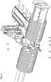
- in einer schematischen, perspektivischen Darstellung eine Drahtschweißmaschine mit zwei Greifern zum Greifen von Enden von Drähten,
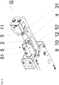
- Fig. 2 bis Fig. 9
- einen der Greifer oder wesentliche Teile eines der Greifer in verschiedenen Zuständen und aus verschiedenen Perspektiven.
- Mit der in der
Fig. 1 dargestellten Drahtschweißmaschine S können die Enden D1 von Drähten D, insbesondere Bewehrungs- oder Betonstahldrähte mit einem Durchmesser von 6 bis 40 mm, durch Schweißung mit einander verbunden werden. - Dazu werden die Enden D1 der Drähte D zueinander ausgerichtet und aneinander gelegt, so dass sich nach einem Fügen der Enden durch Schweißung ein knickfreier Übergang von einem Draht D zum anderen Draht D an der Fügestelle ergibt.
- Das Positionieren der Drähte D vor der Schweißung wird - um einen Maschinenbediener zu entlasten - mit Hilfe der Greifer G vorgenommen. Diese Greifer G greifen die Drähte D nahe ihren Enden, so dass die Enden zum Schweißen in eine bekannte Position gebracht werden können und in einer gewünschten Richtung ausgerichtet werden können.
- Eine Schwierigkeit besteht darin, dass die Enden der Drähte D vor dem Fügen keine vorbestimmte Position haben. Die Drähte D werden im Beispiel auf einer Haspel zur Schweißmaschine geliefert. Die Enden der aufgehaspelten Drähte stehen liegen dabei erfahrungsgemäß dicht an dem übrigen, aufgehaspelten Draht an. Die Enden müssen zunächst, bevor sie mit einem Greifer G ergriffen werden können, manuell von einem Maschinenbediener und ggf. mit Hilfe von Werkzeug aus dem aufgehaspelten Draht herausgbogen werden. Nach dem herausbiegen steht das Ende des Drahtes von der Haspel in eine willkürliche Richtung ab.
- Eine Schwierigkeit besteht darin, die Enden der aufgehaspelten Drähte D mit dem Greifer G so zu ergreifen, dass die Enden in einer bestimmten Position zum Greifer G fixiert sind. Erst dann können sie mittel des Greifers G in eine definierte Position, zum Beispiel der Schweißposition überführt werden.
- Die Greifer G sind zum Beispiel an Schwenkarmen A von Robotern R oder Handhabungseinrichtungen angebracht, die es möglich machen die Greifer G in verschiedene Richtungen im Raum zu bewegen und in verschiedene Richtungen im Raum auszurichten. Die Bewegung der Greifer bzw. der Schwenkarme oder von Gliedern der Schwenkarme kann manuell, motorisch oder manuell mit Servounterstützung erfolgen.
- Manuell oder motorisch oder manuell mit Servorunterstützung kann der Greifer G an das Ende eines ersten zu ergreifenden Drahtes herangeführt werden. Ist eine gewünschte Position und Ausrichtung des Drahte und des Greifers zueinander erreicht, ergreift der Greifer G den Draht D, so dass er anschließend vorzugsweise motorisch oder manuell mit Servounterstützung in die Position gebracht werden kann, in der die Schweißung erfolgen kann. Genau so kann ein zweiter zu ergreifender Draht D mit einem zweiten Greifer G ergriffen und das Ende dieses zweiten Drahtes D in eine Schweißposition gebracht werden.
- Haben beide Enden die gewünschte Schweißposition erreicht, kann die Schweißung beginnen.
- Die Greifer G machen es somit möglich die Enden der zu schweißenden Drähte in die gewünschte Schweißposition zu bringen. Das soll, zur Entlastung des Maschinenbedieners mit möglichst wenig Kraftaufwand erfolgen, anders als es bisher üblich ist, denn bisher werden die Enden der Drähte mit zum Teil erheblichem Kraftaufwand manuell positioniert.
- Der Greifer G gemäß den
Figuren 2 bis 10 , weist ein nicht dargestelltes Verbindungsmittel auf, mit der der Greifer G an einen Roboter oder eine Handhabungseinrichtung angeschlossen werden kann. Bei dem dargestellten Greifer G, aber nicht notwendigerweise bei jedem erfindungsgemäßen Greifer G, ist ein Gehäuse 1 vorgesehen, dass mittelbar oder unmittelbar an dem Verbindungsmittel befestigt ist. Das Gehäuse 1 ist nicht in allenFig. 2 bis 9 dargestellt. - In dem Gehäuse 1 ist eine erste Spannbacke 2 des Greifers G angebracht, die relativ zum Gehäuse 1 unbeweglich ist. Dagegen ist eine zweite Spannbacke 3 beweglich zu dem Gehäuse 1. Ebenfalls beweglich zu dem Gehäuse sind ein Auslöser 4, ein Fangmittel 5 und ein Anschlagmittel 6 des Greifers. Fest verbunden mit dem Gehäuse 1 ist eine Haube 7. Nicht alle Komponenten des Greifers G sind in den
Figuren 2 bis 10 dargestellt. In einigen Figuren sind einige Komponenten des Greifers G nicht dargestellt, um andere Komponenten klarer darstellen zu können. - Die zweite Spannbacke 3 des dargestellten Greifers G, aber nicht notwendigerweise jedes erfindungsgemäßen Greifers G, ist über einen Spannbackenarm 31 schwenkbar an einem Lagerteil 9 gelagert. Das Lagerteil 9 ist in einer Linearführung (nicht dargestellt) im Gehäuse 1 linear verschiebbar geführt.
- Die Linearbewegung des Lagerteils 9 und in Folge dessen der zweiten Spannbacke 3 wird durch einen Antrieb bewirkt, der nicht vollständig dargestellt ist. Der Antrieb ist zumindest zum Teil in dem Gehäuse 1 untergebracht. Der Antrieb kann ein Elektroantrieb, ein Pneumatikantrieb oder ein Hydraulikantrieb sein.
- Im dargestellten Beispiel wird das Lagerteil 9 durch eine Kolbenstange gebildet, die in einem Zylinder (nicht dargestellt) linear geführt ist. Kolbenstange 9 und Zylinder sind Teile eines Hydraulikantrieb zum Bewegen der zweiten Spannbacke.
- Im Gehäuse 1 ist ferner zumindest eine Kulisse 8 mit einem Schlitz (
Fig. 9 ) oder einer Nut (übrige Figuren, insbesondereFig. 7 ) befestigt. Der Schlitz bzw. die Nut hat einen gebogenen ersten Bereich 81, an den sich ein gerader Bereich 82 anschließt. In dem Schlitz bzw. der Nut ist ein Kulissenstein 10 geführt, der fest mit dem Spannbackenarm 31 der zweiten Spannbacke verbunden 3 ist. Der dargestellte Greifer weist zwei Kulissen 8 auf, eine auf der Oberseite, eine auf der Unterseite des Greifers G. In jeder Kulisse 8 ist ein Kulissenstein 10 vorgesehen. - Durch eine lineare Bewegung des Lagerteils 9 werden die Kulissensteine 10 in den Schlitzen bzw. Nuten der Kulissen 8 bewegt. Durch die Bewegung der Kulissensteine 10 wird in der Folge eine Bewegung der zweiten Spannbacke 3 gesteuert. Aufgrund des ersten, gebogenen Bereichs jedes Schlitzes bzw. der Nuten der Kulissen 8 bewegt sich die zweite Spannbacke 3 bei einer Bewegung der Kulissensteine 10 in dem ersten, gebogenen Bereich 81 des Schlitzes bzw. der Nut der Kulissen 8 entlang einer gebogenen Bahn, die dem ersten Bereich 81 der Kulisse 8 ähnlich ist. Aufgrund einer Bewegung der Kulissensteine 10 in dem zweiten, geraden Bereich 82 jedes Schlitzes bzw. jeder Nut der Kulisse 8 vollzieht die zweite Spannbacke eine gerade Bewegung.
- Bei einer Bewegung der Kulissensteine 10 in den Schlitzen der Kulissen 8 aufgrund der Linearbewegung des Lagerteils 9 erreicht die zweite Spannbacke 3 u.a. eine erste, zweite und eine dritte Position, die näher erläutert werden.
- Die erste Position nimmt die zweite Spannbacke 3 ein, wenn der Kulissenstein 10 am freien, vom zweiten Bereich 82 entfernten Ende des ersten Bereichs 81 ist. Die zweite Spannbacke 3 ist dann nach außen geschwenkt und aus einem Bereich benachbart zur ersten Spannbacke 2 gebracht.
- Die zweite Position hat die zweite Spannbacke 3 erreicht, wenn die Kulissensteine 10 den Übergang vom ersten Bereich 81 des Schlitzes bzw. der Nut zum zweiten Bereich 82 des Schlitzes bzw. der Nut der Kulisse 8 erreicht haben. Die zweite Spannbacke 3 liegt dann der ersten Spannbacke 2 gegenüber, der der ersten Spannbacke 2 benachbarte Bereich liegt zwischen den beiden Spannbacken 2, 3.
- Die dritte Position hat die zweite Spannbacke 3 erreicht, wenn die Kulissensteine 10 das freie, dem ersten Bereich 81 abgewandte Ende des zweiten Bereichs 82 jedes Schlitzes bzw. jeder Nut erreicht haben. Zwischen der zweiten und der dritten Position führt die zweite Spannbacke 3 eine lineare Bewegung aus. Die zweite Spannbacke 3 wird dabei gegen die erste Spannbacke 2 bewegt, wodurch zwischen den beiden Spannbacken 2, 3 ein Gegenstand, zum Beispiel ein Draht D eingeklemmt werden kann.
- In der ersten Position der zweiten Spannbacke 3 ist diese in der Haube 7 untergebracht, die sich seitlich von der ersten Spannbacke 2 erstreckt. In der Haube 7 ist die zweite Spannbacke 3 in ihrer ersten Position vor Beschädigungen, zum Beispiel aufgrund einer Kollision mit einem Draht D oder anderem geschützt.
- Das Fangmittel 5 ist ebenfalls linear beweglich geführt mittelbar oder unmittelbar an dem Gehäuse 1 befestigt. Das Fangmittel 5 umfasst einen Stab 51, an dem eine Platte 52 mit Schrauben befestigt ist. Der Stab 51 ist in dem Gehäuse 1 linear verschiebbar geführt. An der Platte 52 ist ein Vorsprung vorgesehen, dessen Zweck noch später erläutert wird. Das Fangmittel 5 ist seitlich neben der ersten Spannbacke 2 angeordnet. Es kann eine erste Position einnehmen, in der es nicht oder nur unwesentlich über die erste Spannbacke 2 hinaus- und in den der ersten Spannbacke 2 benachbarten Bereich hineinragt. In einer zweiten Position ragt das Fangmittel 5 über die erste Spannbacke 2 hinaus und begrenzt den der ersten Spannbacke 2 benachbarten Bereich seitlich.
- Die Bewegung des Fangmittels 5 von der ersten Position in die zweite Position wird durch eine Feder (nicht dargestellt) bewirkt. Dabei kann es sich um eine Schraubendruckfeder handeln. Die Bewegung des Fangmittels 5 von der zweiten Position in die erste Position wird dagegen durch die Bewegung der zweiten Spannbacke 3 aus der zweiten in die dritte Position der zweiten Spannbacke 2 bewirkt, wozu ein Mitnehmer 11 an der zweiten Spannbacke 3 befestigt ist. Der Mitnehmer 11 kommt bei der Bewegung der zweiten Spannbacke 3 in die dritte Position zur Anlage an dem Fangmittel 5, wodurch dieses bei einer weiteren Bewegung der zweiten Spannbacke 3 bzw. des Mitnehmers 11 gegen den Druck der Schraubenfeder in die erste Position bewegt wird.
- Bei dem Auslöser 4 handelt es sich um einen schwenkbar am Gehäuse 1 oder der ersten Spannbacke 2 befestigten Stab, der in einer ersten Position in den der ersten Spannbacke 2 benachbarten Bereich eingeschwenkt ist. In dieser ersten Stellung ist eine Falle 12, die an dem Auslöser 4 befestigt ist, an dem Vorsprung der Platte 52 des Fangmittels 5 eingehakt. Dadurch ist das Fangmittel 5 in seiner ersten Position gegen den Druck der Schraubenfeder fixiert. Die Falle 12 ist zwischen einem Schwenklager, über das der Auslöser 4 an dem Gehäuse 1 oder der ersten Spannbacke 2 gelagert ist, und einem freien Ende des Auslösers 4 vorgesehen, das in den der ersten Spannbacke 2 benachbarten Bereich hineinragt.
- Um in seine zweite Position zu gelangen, wird der Auslöser 4 aus dem der ersten Spannbacke 2 benachbarten Bereich herausgeschwenkt und zwar in Richtung weg von dem Fangmittel 5. Dadurch kommt die Falle 12 von dem Vorsprung an der Platte 52 des Fangmittels 5 frei und das Fangmittel 5 schnellt aufgrund des Drucks der Schraubenfeder in seine zweite Position. Wird das Fangmittel 5 zurück in die erste Position bewegt, gleitet der Vorsprung entlang einer Schrägen der Falle 12 und schwenkt so den Auslöser 4 zurück in seine erste Position, in welcher der Auslöser 4 das Fangmittel 5 in seiner ersten Position hält.
- Das Anschlagmittel 6 weist eine Platte 61 auf, die über zwei Paare von parallelen Stangen 62 (Parallellenker) an dem Gehäuse 1 beweglich befestigt ist. Die Platte 61 kann über die Stangen 62 im Raum bewegt werden, ohne dass sich die Ausrichtung der Platte 61 ändert. Die Platte 61 des Anschlagmittels 6 kann aus einer ersten Position in eine zweite Position gebracht werden, in der sie den Bereich benachbart zu der ersten Spannbacke 2 nach unten begrenzt.
- In der ersten Position ist das Anschlagmittel 6 aus dem Bereich heraus gebracht.
- Das Greifen eines Drahtes D mit dem erfindungsgemäßen Greifer G erfolgt in zwei Schritten.
- In der Ausgangssituation sind das Fangmittel 5, der Auslöser 4, das Anschlagmittel 6 und die zweite Spannbacke 3 in ihren ersten Positionen. Der Greifer G wird nun an den zu ergreifenden Draht D herangeführt oder der zu ergreifenden Draht D wird an den Greifer G herangeführt und zwar so, dass der Draht D in den Greifer eingelegt wird und in den Bereich benachbart zu der ersten Spannbacke 2 kommt. Die Antriebe des Roboters R oder des Handhabungsgerätes sind dann vorzugsweise stillgesetzt. Der Maschinenbediener darf sich dann in einem Sicherheitsbereich um den Roboter R bzw. des Handhabungsgerätes aufhalten und den Draht manuell an den Greifer heranführen oder umgekehrt. Es ist ausreichend, wenn der Draht oder der Greifer nur geringe Wege zurücklegt.
- Beim Einlegen des Drahtes in den Greifer stößt der Draht D gegen den Auslöser 4 und drückt den Auslöser 4 aus seiner ersten in seine zweite Position. Dadurch schnellt das nun freigegebene Fangmittel 5 aus seiner ersten Position in seine zweite Position nach vorne und begrenzt dann den Bereich benachbart zu der ersten Schwenkbacke 2, in dem sich ein Teil des Drahtes D befindet, seitlich, so dass sich der Draht D nicht mehr so leicht aus diesem Bereich herausbewegt. Der Draht D ist dann im Verhältnis zum Greifer G grob positioniert. Das Hervorschnellen des Fangmittels 5 erfolgt mit einer Schnelligkeit und Kraft die ausreichend sind, um den Draht D zügig einzufangen, die andererseits aber so gering sind, dass das Hervorschnellen des Fangmittels 5 keine Gefahr für den Bediener darstellen kann, wenn zum Beispiel ein Körperteil in den Weg des Fangmittels 5 kommt.
- Dadurch der Auslöser 4 beim Einlegen des Drahtes D betätigt wird und das Fangmittel 5 den Draht D fängt und grob positioniert, ist unnötig das Fangmittel 5 durch die Betätigung eine Handschalters oder -tasters oder Fußschalters oder -tasters zu auslösen. Der Bedienter hat damit beide Hände frei, um den Draht D in den Greifer einzulegen bzw. hat einen sicheren Stand während des Einlegevorgangs.
- Anschließend wird das Anschlagmittel 6 manuell oder maschinell aus seiner ersten in seine zweite Position geschwenkt. Die Lage des Greifers G zum Draht D wird dann so korrigiert, dass das Ende des Drahtes D an dem Anschlagmittel 6, nämlich der Platte des Anschlagmittels 6 anschlägt. Damit ist die Höhenlage des Greifers G zum Draht exakt eingestellt.
- Anschließend verlässt der Bediener den Sicherheitsbereich um den Roboter R oder das Handhabungsgerät. Die Antriebe des Roboters werden wieder eingeschaltet gesetzt und ggf. auch betrieben.
- Im Weiteren wird der Antrieb des Lagermittels 9 in Betrieb gesetzt, um die zweite Schwenkbacke 3 in ihre zweite Position zu überführen. Dabei schwenkt die zweite Schwenkbacke 3 in den Bereich benachbart zur ersten Schwenkbacke ein, so dass der Draht D zwischen den beiden Schwenkbacken 2, 3, dem Fangmittel 5 und dem Auslöser 4 zum Liegen kommt. Durch eine weitere Bewegung der zweiten Schwenkbacke 2 in Richtung ihrer dritten Position wird dann der Draht D zwischen den beiden Schwenkbacken 2, 3 geklemmt. Dadurch ist die Position des Drahtes D zum Greifer G exakt bestimmt. Das Anschlagmittel 6 wird zurück in seine erste Position geschwenkt, so dass das Ende des Drahtes D frei zugänglich ist. Durch eine Bewegung des Greifers G wird dann das Ende des Drahtes D in seine Schweißposition überführt.
Claims (19)
- Greifer (G) zum Greifen von Enden (D1) von Drähten (D),- mit wenigstens einem Verbindungsmittel, mit der der Greifer (G) an einem Arm (A) insbesondere eines Roboters (R) oder einer Handhabungseinrichtung befestigbar ist,- mit einer ersten Spannbacke (2),- mit einer zweiten Spannbacke (3) und- mit einem ersten Antrieb,- wobei zumindest die zweite Spannbacke (3) mit dem ersten Antrieb gekoppelt ist und mittels des Antriebs relativ zu der ersten Spannbacke (2) und dem Verbindungsmittel zwischen zumindest einer ersten Position und einer zweiten Position bewegbar ist und- wobei in der ersten Position der zweiten Spannbacke (3) ein Draht (D) in einen Bereich benachbart zu der ersten Spannbacke (2) einbringbar ist und in der zweiten Position der zweiten Spannbacke (3) ein Draht (D) zwischen der ersten und der zweiten Spannbacke (2, 3) einspannbar ist,dadurch gekennzeichnet, dass
der Greifer (G) ein Fangmittel (5) aufweist, welches aus einer ersten Position in eine zweite Position bewegbar ist, wobei das Fangmittel (5) in der zweiten Position den Bereich benachbart zu der ersten Spannbacke (2) zumindest einseitig begrenzt. - Greifer (G) nach Anspruch 1, dadurch gekennzeichnet, dass das Fangmittel (5) mittels einer Feder aus seiner ersten in seine zweite Position bewegbar ist.
- Greifer (G) nach Anspruch 1 oder 2, dadurch gekennzeichnet, dass der Greifer (G) einen Auslöser (4) aufweist, der mit dem Fangmittel (5) und/oder der Feder gekoppelt ist, um die Bewegung des Fangmittels (5) aus seiner ersten Position in seine zweite Position auszulösen.
- Greifer (G) nach Anspruch 3, dadurch gekennzeichnet, dass der Auslöser (4) in einem nicht ausgelösten Zustand in den Bereich benachbart zu der ersten Spannbacke (2) hineinragt und in einem ausgelösten Zustand außerhalb des Bereichs benachbart zu der ersten Spannbacke (2) ist.
- Greifer (G) nach einem der Ansprüche 1 bis 4, dadurch gekennzeichnet, dass die zweite Spannbacke (3) aus der zweiten Position in eine dritte Position bewegbar ist.
- Greifer (G) nach einem der Ansprüche 1 bis 5, dadurch gekennzeichnet, dass mittels der zweiten Spannbacke (3) und/oder einem mit der zweiten Spannbacke (2) verbundenem Gegenstand (11) das Fangmittel (5) aus der zweiten Position in die erste Position bewegbar ist.
- Greifer (G) nach einem der Ansprüche 1 bis 6, dadurch gekennzeichnet, dass das Fangmittel (5) in der ersten Position durch eine Falle (12) oder einen Haken am Auslöser (4) gehalten ist.
- Greifer (G) nach einem der Ansprüche 1 bis 7, dadurch gekennzeichnet, dass die zweite Spannbacke (3) schwenkbar an einem Lagerteil (9) gelagert ist.
- Greifer (G) nach Anspruch 8, dadurch gekennzeichnet, dass das Lagerteil (9) linear verschiebbar am und/oder zum Verbindungsmittel gelagert ist.
- Greifer (G) nach Anspruch 9, dadurch gekennzeichnet, dass der Greifer (G) eine mit dem Verbindungmittel fest verbundene Kulisse (8) und einen mit dem der zweiten Spannbacke (3) verbundenen Kulissenstein (10) aufweist, wobei der Kulissenstein (10) in der Kulisse (8) angeordnet ist.
- Greifer (G) nach Anspruch 10, dadurch gekennzeichnet, dass die Kulisse (8) einen Schlitz mit einem ersten gebogenen Bereich (81) und einem zweiten, an den ersten Bereich (81) anschließenden, geraden Bereich (82) hat.
- Greifer (G) nach Anspruch 11, dadurch gekennzeichnet, dass die zweite Spannbacke (3) in der ersten Position ist, wenn der Kulissenstein (10) in einer ersten Position am vom zweiten Bereich (82) abgewandten Ende des ersten Bereichs (81) des Schlitzes der Kulisse (8) ist.
- Greifer (G) nach Anspruch 11 oder 12, dadurch gekennzeichnet, dass die zweite Spannbacke (3) in der zweiten Position ist, wenn sich der Kulissenstein (10) in einer zweiten Position an einem Ort des Schlitzes der Kulisse (8) am Übergang vom ersten (81) zum zweiten Bereich (82) oder benachbart zu diesem Ort befindet.
- Greifer (G) nach einem der Ansprüche 11 bis 13, dadurch gekennzeichnet, dass die zweite Spannbacke (3) in der dritten Position ist, wenn der Kulissenstein (10) in einer dritten Position am vom ersten Bereich (81) abgewandten Ende des zweiten Bereichs (82) des Schlitzes der Kulisse (8) ist.
- Greifer (G) nach einem der Ansprüche 1 bis 14, dadurch gekennzeichnet, dass der Greifer (G) ein Anschlagmittel (6) aufweist, das zwischen einer ersten Position und einer zweiten Position beweglich ist, wobei das Anschlagmittel (6) in der ersten Position einen Anschlag für das Ende (D1) eines vom Greifer (G) aufgenommenen Drahtes (D) ist, während in der zweiten Position des Anschlagmittel (6) das Ende (D1) des Drahtes (D) frei vom Anschlagmittel (6) ist.
- Greifer (G) nach einem der Ansprüche 1 bis 15, dadurch gekennzeichnet, dass der Greifer (G) eine Haube (7) aufweist, in welcher die zweite Spannbacke (3) in der ersten Position untergebracht ist.
- Roboter (R) oder Handhabungsgerät für Draht, insbesondere zum Zuführen von Enden (D1) zu verschweißender Drähte (D) in eine Drahtschweißmaschine, mit einem Arm und einem an dem Arm befestigten Greifer, dadurch gekennzeichnet, dass der Greifer ein Greifer nach einem der Ansprüche 1 bis 16 ist.
- Drahtschweißmaschine (S) mit wenigstens einem Roboter (R) oder Handhabungsgerät zum Zuführen von Enden (D1) zu verschweißender Drähte (D), wobei der Roboter (R) oder das Handhabungsgerät wenigstens einen Greifer (G) zum Greifen von Enden (D1) des Drahtes (D) nach einem der Ansprüche 1 bis 16 aufweist.
- Verfahren zum Greifen eines Drahtes und Positionieren des Endes des Drahtes mit einem Greifer, insbesondere nach einem der Ansprüche 1 bis 16, gekennzeichnet durch- das Heranführen des Drahtes an den Greifer oder das Heranführen des Greifers an den Draht,- das Einlegen des Drahtes in den Greifer in einen Bereich benachbart einer ersten Spannbacke des Greifers, wobei bei Einlegen ein Auslöser eine Bewegung eines Fangmittels aus einer ersten in eine zweite Position auslöst,- das Begrenzen des Bereichs benachbart einer ersten Spannbacke des Greifers, in dem der eingelegte Draht bewegt werden kann durch das in der zweiten Position befindliche Fangmittel des Greifers,- das Positionieren des Drahtes in dem Greifers mittels wenigstens eines Anschlagmittels,- das Bewegen einer zweiten Spannbacke relativ zur ersten Spannbacke zum Einspannen des Drahtes und- das Positionieren des Greifers mit dem eingespannten Draht in einer vorbestimmten Position.
Priority Applications (8)
| Application Number | Priority Date | Filing Date | Title |
|---|---|---|---|
| ES16175331.4T ES2693117T3 (es) | 2016-06-20 | 2016-06-20 | Pinza y procedimiento para agarrar los extremos de alambres y soldadora de hilo y robot con dichas pinzas |
| EP16175331.4A EP3260231B8 (de) | 2016-06-20 | 2016-06-20 | Greifer und verfahren zum greifen von enden von drähten und drahtschweissmaschine und roboter mit derartigen greifern |
| DK16175331.4T DK3260231T3 (en) | 2016-06-20 | 2016-06-20 | GRIBERS AND PROCEDURE TO Grab END OF WIRE AND WIRE MACHINE AND ROBOT WITH SUCH GRABERS |
| PL16175331T PL3260231T3 (pl) | 2016-06-20 | 2016-06-20 | Chwytak i sposób chwytania końców drutów oraz zgrzewarka drutów i robot z takimi chwytakami |
| LTEP16175331.4T LT3260231T (lt) | 2016-06-20 | 2016-06-20 | Spaustuvai, vielų galų suspaudimo būdas, vielų suvirinimo mašina ir robotas su tokiais spaustuvais |
| TR2018/15320T TR201815320T4 (tr) | 2016-06-20 | 2016-06-20 | Tutucu ve tellerin uçlarının tutulmasına yönelik yöntem ve bu tür tutuculara sahip tel kaynak makinesi ve robot. |
| SI201630094T SI3260231T1 (sl) | 2016-06-20 | 2016-06-20 | Prijemalo in postopek za prijemanje koncev žic ter varilni stroj za žice in robot s tovrstnimi prijemali |
| HRP20181688TT HRP20181688T1 (hr) | 2016-06-20 | 2018-10-16 | Hvataljka, postupak hvatanja krajeva žica, stroj za zavarivanje žica te robot s takvim hvataljkama |
Applications Claiming Priority (1)
| Application Number | Priority Date | Filing Date | Title |
|---|---|---|---|
| EP16175331.4A EP3260231B8 (de) | 2016-06-20 | 2016-06-20 | Greifer und verfahren zum greifen von enden von drähten und drahtschweissmaschine und roboter mit derartigen greifern |
Publications (3)
| Publication Number | Publication Date |
|---|---|
| EP3260231A1 EP3260231A1 (de) | 2017-12-27 |
| EP3260231B1 true EP3260231B1 (de) | 2018-08-29 |
| EP3260231B8 EP3260231B8 (de) | 2019-06-26 |
Family
ID=56235612
Family Applications (1)
| Application Number | Title | Priority Date | Filing Date |
|---|---|---|---|
| EP16175331.4A Active EP3260231B8 (de) | 2016-06-20 | 2016-06-20 | Greifer und verfahren zum greifen von enden von drähten und drahtschweissmaschine und roboter mit derartigen greifern |
Country Status (8)
| Country | Link |
|---|---|
| EP (1) | EP3260231B8 (de) |
| DK (1) | DK3260231T3 (de) |
| ES (1) | ES2693117T3 (de) |
| HR (1) | HRP20181688T1 (de) |
| LT (1) | LT3260231T (de) |
| PL (1) | PL3260231T3 (de) |
| SI (1) | SI3260231T1 (de) |
| TR (1) | TR201815320T4 (de) |
Families Citing this family (2)
| Publication number | Priority date | Publication date | Assignee | Title |
|---|---|---|---|---|
| CN117260785B (zh) * | 2023-09-18 | 2026-02-17 | 江苏嘉拓新能源智能装备股份有限公司 | 一种单驱动定位夹取机构 |
| CN118321467B (zh) * | 2024-04-09 | 2024-09-03 | 无锡恒泰照明科技有限公司 | 一种电动自行车灯珠焊线机的物料输送设备 |
Family Cites Families (2)
| Publication number | Priority date | Publication date | Assignee | Title |
|---|---|---|---|---|
| DK173182B1 (da) * | 1995-03-16 | 2000-03-06 | Jan Dall Christensen | Gribeorgan med holdekæber eller gribefingre til håndtering af stangformede emner. |
| CN204800628U (zh) | 2015-05-05 | 2015-11-25 | 安徽省振华科技工业有限公司 | 一种机械手臂 |
-
2016
- 2016-06-20 EP EP16175331.4A patent/EP3260231B8/de active Active
- 2016-06-20 TR TR2018/15320T patent/TR201815320T4/tr unknown
- 2016-06-20 DK DK16175331.4T patent/DK3260231T3/en active
- 2016-06-20 PL PL16175331T patent/PL3260231T3/pl unknown
- 2016-06-20 ES ES16175331.4T patent/ES2693117T3/es active Active
- 2016-06-20 SI SI201630094T patent/SI3260231T1/sl unknown
- 2016-06-20 LT LTEP16175331.4T patent/LT3260231T/lt unknown
-
2018
- 2018-10-16 HR HRP20181688TT patent/HRP20181688T1/hr unknown
Non-Patent Citations (1)
| Title |
|---|
| None * |
Also Published As
| Publication number | Publication date |
|---|---|
| SI3260231T1 (sl) | 2018-12-31 |
| TR201815320T4 (tr) | 2018-11-21 |
| PL3260231T3 (pl) | 2019-01-31 |
| DK3260231T3 (en) | 2018-11-05 |
| EP3260231B8 (de) | 2019-06-26 |
| ES2693117T3 (es) | 2018-12-07 |
| LT3260231T (lt) | 2018-11-12 |
| HRP20181688T1 (hr) | 2018-12-28 |
| EP3260231A1 (de) | 2017-12-27 |
Similar Documents
| Publication | Publication Date | Title |
|---|---|---|
| EP1970139B1 (de) | Greifvorrichtung zum Ergreifen und Haltern länglicher Werkstücke, insbesondere bei Biegemaschinen | |
| AT517912B1 (de) | Fertigungsanlage zum Fertigen von Bewehrungselementen | |
| EP2913162B1 (de) | Leitungs-rückzugsystem | |
| CH616096A5 (de) | ||
| DE2545345A1 (de) | Verfahren und vorrichtung zur herstellung von elektrischen leitern mit einer bestimmten laenge | |
| DE112015000936B9 (de) | Spannvorrichtung | |
| DE2166983B2 (de) | Chirurgisches Instrument zum Herumlegen von Klammern zum Abbinden rohrförmiger organischer Gebilde | |
| DE2455702A1 (de) | Verfahren und vorrichtung zur besseren zugaenglichmachung des werkzeugraumes einer formmaschine | |
| DE2840944A1 (de) | Verfahren und maschine zum umschnueren eines gegenstandes | |
| DE112015001669T5 (de) | Spannvorrichtung | |
| EP4059125B1 (de) | Verfahren zum umformen eines in einem statorkern angeordneten leiterstücks sowie entsprechende vorrichtung | |
| DE102018108863A1 (de) | Biegevorrichtung für längliche Werkstücke | |
| EP2428452B1 (de) | Verfahren und Umreifungsvorrichtung zum Anlegen von Umreifungsbändern um Packstücke | |
| DE69006137T2 (de) | Bindevorrichtung mit Verdrillkopf und mit solchen Bindevorrichtungen ausgerüstete Bindemaschinen, vorzugsweise für das Binden von Metalldrahtbündeln. | |
| DE102017001334A1 (de) | Anordnung zum Eindrehen einer Mehrzahl von Schrauben | |
| EP3260231B1 (de) | Greifer und verfahren zum greifen von enden von drähten und drahtschweissmaschine und roboter mit derartigen greifern | |
| DE2341886A1 (de) | Verfahren und vorrichtung zum aufspreizen von metall | |
| DE102011014953B4 (de) | Biegevorrichtung für stab- und rohrförmige Werkstücke | |
| EP3542963B1 (de) | Hackenspanner | |
| DE2843531C2 (de) | Maschine zum Herstellen von gitterträgerartigen Bewehrungsgebilden für Stahlbeton | |
| WO2015185493A1 (de) | Greifbackensicherung | |
| DD229325A5 (de) | Betaetigungsvorrichtung zur verwendung in einer giessereianlage | |
| DE7416105U (de) | Vorrichtung zum endseitigen Verbinden von zwei Längenabschnitten aus Bandoder Blechmaterial durch Abbrennschweißen | |
| DE2540644C3 (de) | Längenveränderbare Stange, insbesondere Erdungsstange oder Betätigungsstange für elektrotechnische Einrichtungen | |
| EP3302843B1 (de) | Biegewerkzeug für eine biegepresse und verfahren zum manipulieren eines solchen biegewerkzeuges |
Legal Events
| Date | Code | Title | Description |
|---|---|---|---|
| PUAI | Public reference made under article 153(3) epc to a published international application that has entered the european phase |
Free format text: ORIGINAL CODE: 0009012 |
|
| STAA | Information on the status of an ep patent application or granted ep patent |
Free format text: STATUS: REQUEST FOR EXAMINATION WAS MADE |
|
| 17P | Request for examination filed |
Effective date: 20170428 |
|
| AK | Designated contracting states |
Kind code of ref document: A1 Designated state(s): AL AT BE BG CH CY CZ DE DK EE ES FI FR GB GR HR HU IE IS IT LI LT LU LV MC MK MT NL NO PL PT RO RS SE SI SK SM TR |
|
| AX | Request for extension of the european patent |
Extension state: BA ME |
|
| GRAP | Despatch of communication of intention to grant a patent |
Free format text: ORIGINAL CODE: EPIDOSNIGR1 |
|
| STAA | Information on the status of an ep patent application or granted ep patent |
Free format text: STATUS: GRANT OF PATENT IS INTENDED |
|
| RIC1 | Information provided on ipc code assigned before grant |
Ipc: B23K 37/04 20060101AFI20180323BHEP Ipc: B23K 101/32 20060101ALN20180323BHEP Ipc: B25J 15/00 20060101ALI20180323BHEP Ipc: B25J 15/02 20060101ALI20180323BHEP Ipc: B21F 15/08 20060101ALI20180323BHEP |
|
| INTG | Intention to grant announced |
Effective date: 20180413 |
|
| GRAS | Grant fee paid |
Free format text: ORIGINAL CODE: EPIDOSNIGR3 |
|
| GRAA | (expected) grant |
Free format text: ORIGINAL CODE: 0009210 |
|
| STAA | Information on the status of an ep patent application or granted ep patent |
Free format text: STATUS: THE PATENT HAS BEEN GRANTED |
|
| RAV | Requested validation state of the european patent: fee paid |
Extension state: MA Effective date: 20180627 Extension state: MD Effective date: 20180627 |
|
| RAX | Requested extension states of the european patent have changed |
Extension state: BA Payment date: 20180627 Extension state: ME Payment date: 20180627 |
|
| AK | Designated contracting states |
Kind code of ref document: B1 Designated state(s): AL AT BE BG CH CY CZ DE DK EE ES FI FR GB GR HR HU IE IS IT LI LT LU LV MC MK MT NL NO PL PT RO RS SE SI SK SM TR |
|
| AX | Request for extension of the european patent |
Extension state: BA ME |
|
| REG | Reference to a national code |
Ref country code: GB Ref legal event code: FG4D Free format text: NOT ENGLISH |
|
| REG | Reference to a national code |
Ref country code: CH Ref legal event code: EP |
|
| REG | Reference to a national code |
Ref country code: AT Ref legal event code: REF Ref document number: 1034565 Country of ref document: AT Kind code of ref document: T Effective date: 20180915 |
|
| REG | Reference to a national code |
Ref country code: IE Ref legal event code: FG4D Free format text: LANGUAGE OF EP DOCUMENT: GERMAN |
|
| REG | Reference to a national code |
Ref country code: DE Ref legal event code: R096 Ref document number: 502016001796 Country of ref document: DE |
|
| REG | Reference to a national code |
Ref country code: HR Ref legal event code: TUEP Ref document number: P20181688 Country of ref document: HR |
|
| REG | Reference to a national code |
Ref country code: DK Ref legal event code: T3 Effective date: 20181022 |
|
| REG | Reference to a national code |
Ref country code: SE Ref legal event code: TRGR |
|
| REG | Reference to a national code |
Ref country code: NL Ref legal event code: FP |
|
| REG | Reference to a national code |
Ref country code: ES Ref legal event code: FG2A Ref document number: 2693117 Country of ref document: ES Kind code of ref document: T3 Effective date: 20181207 |
|
| REG | Reference to a national code |
Ref country code: NO Ref legal event code: T2 Effective date: 20180829 |
|
| REG | Reference to a national code |
Ref country code: HR Ref legal event code: T1PR Ref document number: P20181688 Country of ref document: HR |
|
| REG | Reference to a national code |
Ref country code: EE Ref legal event code: FG4A Ref document number: E016403 Country of ref document: EE Effective date: 20181019 |
|
| PG25 | Lapsed in a contracting state [announced via postgrant information from national office to epo] |
Ref country code: IS Free format text: LAPSE BECAUSE OF FAILURE TO SUBMIT A TRANSLATION OF THE DESCRIPTION OR TO PAY THE FEE WITHIN THE PRESCRIBED TIME-LIMIT Effective date: 20181229 Ref country code: GR Free format text: LAPSE BECAUSE OF FAILURE TO SUBMIT A TRANSLATION OF THE DESCRIPTION OR TO PAY THE FEE WITHIN THE PRESCRIBED TIME-LIMIT Effective date: 20181130 Ref country code: RS Free format text: LAPSE BECAUSE OF FAILURE TO SUBMIT A TRANSLATION OF THE DESCRIPTION OR TO PAY THE FEE WITHIN THE PRESCRIBED TIME-LIMIT Effective date: 20180829 Ref country code: FI Free format text: LAPSE BECAUSE OF FAILURE TO SUBMIT A TRANSLATION OF THE DESCRIPTION OR TO PAY THE FEE WITHIN THE PRESCRIBED TIME-LIMIT Effective date: 20180829 |
|
| REG | Reference to a national code |
Ref country code: SK Ref legal event code: T3 Ref document number: E 28787 Country of ref document: SK |
|
| PG25 | Lapsed in a contracting state [announced via postgrant information from national office to epo] |
Ref country code: AL Free format text: LAPSE BECAUSE OF FAILURE TO SUBMIT A TRANSLATION OF THE DESCRIPTION OR TO PAY THE FEE WITHIN THE PRESCRIBED TIME-LIMIT Effective date: 20180829 |
|
| PG25 | Lapsed in a contracting state [announced via postgrant information from national office to epo] |
Ref country code: CZ Free format text: LAPSE BECAUSE OF FAILURE TO SUBMIT A TRANSLATION OF THE DESCRIPTION OR TO PAY THE FEE WITHIN THE PRESCRIBED TIME-LIMIT Effective date: 20180829 Ref country code: RO Free format text: LAPSE BECAUSE OF FAILURE TO SUBMIT A TRANSLATION OF THE DESCRIPTION OR TO PAY THE FEE WITHIN THE PRESCRIBED TIME-LIMIT Effective date: 20180829 |
|
| VS25 | Lapsed in a validation state [announced via postgrant information from nat. office to epo] |
Ref country code: MD Free format text: LAPSE BECAUSE OF FAILURE TO SUBMIT A TRANSLATION OF THE DESCRIPTION OR TO PAY THE FEE WITHIN THE PRESCRIBED TIME-LIMIT Effective date: 20180829 Ref country code: MA Free format text: LAPSE BECAUSE OF FAILURE TO SUBMIT A TRANSLATION OF THE DESCRIPTION OR TO PAY THE FEE WITHIN THE PRESCRIBED TIME-LIMIT; INVALID AB INITIO Effective date: 20160620 |
|
| PG25 | Lapsed in a contracting state [announced via postgrant information from national office to epo] |
Ref country code: SM Free format text: LAPSE BECAUSE OF FAILURE TO SUBMIT A TRANSLATION OF THE DESCRIPTION OR TO PAY THE FEE WITHIN THE PRESCRIBED TIME-LIMIT Effective date: 20180829 |
|
| REG | Reference to a national code |
Ref country code: DE Ref legal event code: R097 Ref document number: 502016001796 Country of ref document: DE Ref country code: CH Ref legal event code: PK Free format text: BERICHTIGUNG B8 |
|
| REG | Reference to a national code |
Ref country code: HR Ref legal event code: ODRP Ref document number: P20181688 Country of ref document: HR Payment date: 20190607 Year of fee payment: 4 |
|
| DAV | Request for validation of the european patent (deleted) | ||
| DAX | Request for extension of the european patent (deleted) | ||
| PLBE | No opposition filed within time limit |
Free format text: ORIGINAL CODE: 0009261 |
|
| STAA | Information on the status of an ep patent application or granted ep patent |
Free format text: STATUS: NO OPPOSITION FILED WITHIN TIME LIMIT |
|
| PGFP | Annual fee paid to national office [announced via postgrant information from national office to epo] |
Ref country code: PL Payment date: 20190530 Year of fee payment: 4 Ref country code: LT Payment date: 20190522 Year of fee payment: 4 |
|
| 26N | No opposition filed |
Effective date: 20190531 |
|
| PGFP | Annual fee paid to national office [announced via postgrant information from national office to epo] |
Ref country code: RS Payment date: 20190425 Year of fee payment: 7 Ref country code: FR Payment date: 20190619 Year of fee payment: 4 Ref country code: BG Payment date: 20190624 Year of fee payment: 4 Ref country code: HR Payment date: 20190607 Year of fee payment: 4 Ref country code: SE Payment date: 20190619 Year of fee payment: 4 Ref country code: EE Payment date: 20190625 Year of fee payment: 4 Ref country code: TR Payment date: 20190620 Year of fee payment: 4 Ref country code: LV Payment date: 20190625 Year of fee payment: 4 |
|
| PGFP | Annual fee paid to national office [announced via postgrant information from national office to epo] |
Ref country code: SK Payment date: 20190528 Year of fee payment: 4 |
|
| PGFP | Annual fee paid to national office [announced via postgrant information from national office to epo] |
Ref country code: ES Payment date: 20190722 Year of fee payment: 4 |
|
| PG25 | Lapsed in a contracting state [announced via postgrant information from national office to epo] |
Ref country code: MC Free format text: LAPSE BECAUSE OF FAILURE TO SUBMIT A TRANSLATION OF THE DESCRIPTION OR TO PAY THE FEE WITHIN THE PRESCRIBED TIME-LIMIT Effective date: 20180829 |
|
| PG25 | Lapsed in a contracting state [announced via postgrant information from national office to epo] |
Ref country code: IE Free format text: LAPSE BECAUSE OF NON-PAYMENT OF DUE FEES Effective date: 20190620 |
|
| PG25 | Lapsed in a contracting state [announced via postgrant information from national office to epo] |
Ref country code: LU Free format text: LAPSE BECAUSE OF NON-PAYMENT OF DUE FEES Effective date: 20190620 |
|
| PG25 | Lapsed in a contracting state [announced via postgrant information from national office to epo] |
Ref country code: PT Free format text: LAPSE BECAUSE OF FAILURE TO SUBMIT A TRANSLATION OF THE DESCRIPTION OR TO PAY THE FEE WITHIN THE PRESCRIBED TIME-LIMIT Effective date: 20181229 |
|
| REG | Reference to a national code |
Ref country code: HR Ref legal event code: PBON Ref document number: P20181688 Country of ref document: HR Effective date: 20200620 |
|
| REG | Reference to a national code |
Ref country code: EE Ref legal event code: MM4A Ref document number: E016403 Country of ref document: EE Effective date: 20200630 |
|
| REG | Reference to a national code |
Ref country code: SK Ref legal event code: MM4A Ref document number: E 28787 Country of ref document: SK Effective date: 20200620 |
|
| PG25 | Lapsed in a contracting state [announced via postgrant information from national office to epo] |
Ref country code: LV Free format text: LAPSE BECAUSE OF NON-PAYMENT OF DUE FEES Effective date: 20200620 |
|
| GBPC | Gb: european patent ceased through non-payment of renewal fee |
Effective date: 20200620 |
|
| REG | Reference to a national code |
Ref country code: LT Ref legal event code: MM4D Effective date: 20200620 |
|
| PG25 | Lapsed in a contracting state [announced via postgrant information from national office to epo] |
Ref country code: GB Free format text: LAPSE BECAUSE OF NON-PAYMENT OF DUE FEES Effective date: 20200620 Ref country code: FR Free format text: LAPSE BECAUSE OF NON-PAYMENT OF DUE FEES Effective date: 20200630 Ref country code: EE Free format text: LAPSE BECAUSE OF NON-PAYMENT OF DUE FEES Effective date: 20200630 Ref country code: LT Free format text: LAPSE BECAUSE OF NON-PAYMENT OF DUE FEES Effective date: 20200620 |
|
| PG25 | Lapsed in a contracting state [announced via postgrant information from national office to epo] |
Ref country code: CY Free format text: LAPSE BECAUSE OF FAILURE TO SUBMIT A TRANSLATION OF THE DESCRIPTION OR TO PAY THE FEE WITHIN THE PRESCRIBED TIME-LIMIT Effective date: 20180829 Ref country code: SE Free format text: LAPSE BECAUSE OF NON-PAYMENT OF DUE FEES Effective date: 20200621 Ref country code: BG Free format text: LAPSE BECAUSE OF NON-PAYMENT OF DUE FEES Effective date: 20201231 |
|
| PG25 | Lapsed in a contracting state [announced via postgrant information from national office to epo] |
Ref country code: SK Free format text: LAPSE BECAUSE OF NON-PAYMENT OF DUE FEES Effective date: 20200620 Ref country code: HR Free format text: LAPSE BECAUSE OF NON-PAYMENT OF DUE FEES Effective date: 20200620 |
|
| PG25 | Lapsed in a contracting state [announced via postgrant information from national office to epo] |
Ref country code: HU Free format text: LAPSE BECAUSE OF FAILURE TO SUBMIT A TRANSLATION OF THE DESCRIPTION OR TO PAY THE FEE WITHIN THE PRESCRIBED TIME-LIMIT; INVALID AB INITIO Effective date: 20160620 Ref country code: MT Free format text: LAPSE BECAUSE OF FAILURE TO SUBMIT A TRANSLATION OF THE DESCRIPTION OR TO PAY THE FEE WITHIN THE PRESCRIBED TIME-LIMIT Effective date: 20180829 |
|
| PGFP | Annual fee paid to national office [announced via postgrant information from national office to epo] |
Ref country code: NL Payment date: 20210618 Year of fee payment: 6 Ref country code: NO Payment date: 20210624 Year of fee payment: 6 |
|
| PG25 | Lapsed in a contracting state [announced via postgrant information from national office to epo] |
Ref country code: SI Free format text: LAPSE BECAUSE OF NON-PAYMENT OF DUE FEES Effective date: 20200621 |
|
| PGFP | Annual fee paid to national office [announced via postgrant information from national office to epo] |
Ref country code: DK Payment date: 20210623 Year of fee payment: 6 Ref country code: AT Payment date: 20210621 Year of fee payment: 6 Ref country code: BE Payment date: 20210618 Year of fee payment: 6 |
|
| REG | Reference to a national code |
Ref country code: SI Ref legal event code: KO00 Effective date: 20210811 |
|
| REG | Reference to a national code |
Ref country code: SE Ref legal event code: EUG |
|
| REG | Reference to a national code |
Ref country code: ES Ref legal event code: FD2A Effective date: 20211027 |
|
| PG25 | Lapsed in a contracting state [announced via postgrant information from national office to epo] |
Ref country code: IT Free format text: LAPSE BECAUSE OF NON-PAYMENT OF DUE FEES Effective date: 20200620 |
|
| PG25 | Lapsed in a contracting state [announced via postgrant information from national office to epo] |
Ref country code: ES Free format text: LAPSE BECAUSE OF NON-PAYMENT OF DUE FEES Effective date: 20200621 |
|
| PG25 | Lapsed in a contracting state [announced via postgrant information from national office to epo] |
Ref country code: TR Free format text: LAPSE BECAUSE OF NON-PAYMENT OF DUE FEES Effective date: 20200620 Ref country code: MK Free format text: LAPSE BECAUSE OF FAILURE TO SUBMIT A TRANSLATION OF THE DESCRIPTION OR TO PAY THE FEE WITHIN THE PRESCRIBED TIME-LIMIT Effective date: 20180829 |
|
| PG25 | Lapsed in a contracting state [announced via postgrant information from national office to epo] |
Ref country code: PL Free format text: LAPSE BECAUSE OF NON-PAYMENT OF DUE FEES Effective date: 20200620 |
|
| REG | Reference to a national code |
Ref country code: NO Ref legal event code: MMEP Ref country code: DK Ref legal event code: EBP Effective date: 20220630 |
|
| REG | Reference to a national code |
Ref country code: NL Ref legal event code: MM Effective date: 20220701 |
|
| REG | Reference to a national code |
Ref country code: AT Ref legal event code: MM01 Ref document number: 1034565 Country of ref document: AT Kind code of ref document: T Effective date: 20220620 |
|
| REG | Reference to a national code |
Ref country code: BE Ref legal event code: MM Effective date: 20220630 |
|
| PG25 | Lapsed in a contracting state [announced via postgrant information from national office to epo] |
Ref country code: NL Free format text: LAPSE BECAUSE OF NON-PAYMENT OF DUE FEES Effective date: 20220701 |
|
| PG25 | Lapsed in a contracting state [announced via postgrant information from national office to epo] |
Ref country code: NO Free format text: LAPSE BECAUSE OF NON-PAYMENT OF DUE FEES Effective date: 20220630 Ref country code: AT Free format text: LAPSE BECAUSE OF NON-PAYMENT OF DUE FEES Effective date: 20220620 |
|
| PG25 | Lapsed in a contracting state [announced via postgrant information from national office to epo] |
Ref country code: BE Free format text: LAPSE BECAUSE OF NON-PAYMENT OF DUE FEES Effective date: 20220630 |
|
| PG25 | Lapsed in a contracting state [announced via postgrant information from national office to epo] |
Ref country code: DK Free format text: LAPSE BECAUSE OF NON-PAYMENT OF DUE FEES Effective date: 20220630 |
|
| P01 | Opt-out of the competence of the unified patent court (upc) registered |
Effective date: 20230626 |
|
| PGFP | Annual fee paid to national office [announced via postgrant information from national office to epo] |
Ref country code: DE Payment date: 20250630 Year of fee payment: 10 |
|
| PGFP | Annual fee paid to national office [announced via postgrant information from national office to epo] |
Ref country code: CH Payment date: 20250701 Year of fee payment: 10 |