EP3260241A1 - Hammer - Google Patents
Hammer Download PDFInfo
- Publication number
- EP3260241A1 EP3260241A1 EP17181499.9A EP17181499A EP3260241A1 EP 3260241 A1 EP3260241 A1 EP 3260241A1 EP 17181499 A EP17181499 A EP 17181499A EP 3260241 A1 EP3260241 A1 EP 3260241A1
- Authority
- EP
- European Patent Office
- Prior art keywords
- longitudinal axis
- ram
- beat piece
- axis
- circular
- Prior art date
- Legal status (The legal status is an assumption and is not a legal conclusion. Google has not performed a legal analysis and makes no representation as to the accuracy of the status listed.)
- Granted
Links
Images



Classifications
-
- B—PERFORMING OPERATIONS; TRANSPORTING
- B25—HAND TOOLS; PORTABLE POWER-DRIVEN TOOLS; MANIPULATORS
- B25D—PERCUSSIVE TOOLS
- B25D17/00—Details of, or accessories for, portable power-driven percussive tools
- B25D17/06—Hammer pistons; Anvils ; Guide-sleeves for pistons
-
- B—PERFORMING OPERATIONS; TRANSPORTING
- B25—HAND TOOLS; PORTABLE POWER-DRIVEN TOOLS; MANIPULATORS
- B25D—PERCUSSIVE TOOLS
- B25D2217/00—Details of, or accessories for, portable power-driven percussive tools
- B25D2217/0011—Details of anvils, guide-sleeves or pistons
- B25D2217/0015—Anvils
-
- B—PERFORMING OPERATIONS; TRANSPORTING
- B25—HAND TOOLS; PORTABLE POWER-DRIVEN TOOLS; MANIPULATORS
- B25D—PERCUSSIVE TOOLS
- B25D2250/00—General details of portable percussive tools; Components used in portable percussive tools
- B25D2250/245—Spatial arrangement of components of the tool relative to each other
Definitions
- the present invention relates to a hammer drill, and in particular, to a hammer drill having a ram which is capable of repetitively striking a cutting tool via a beat piece.
- a typical hammer drill comprises a body in which is mounted an electric motor and a hammer mechanism.
- a tool holder is mounted on the front of the body which holds a cutting tool, such as a drill bit or a chisel.
- the hammer mechanism typically comprises a ram, slideably mounted in a cylinder, reciprocatingly driven by a piston via an air spring, the piston being reciprocatingly driven by the motor via a set of gears and a crank mechanism or wobble bearing.
- the ram in turn repeatedly strikes the end of the cutting tool via a beat piece.
- hammer drill also comprise a rotary drive mechanism which enables the tool holder to rotatingly drive the cutting tool held within the tool holder.
- the cylinder is the form of a rotatable spindle. This can be in addition to the repetitive striking of the end of the cutting tool by the beat piece (in which case, the hammer drill is operating in a hammer and drill mode) or as an alternative to the repetitive striking of the end of the cutting tool by the beat piece by switching off the hammer mechanism (in which case, the hammer drill is operating in a drill only mode).
- EP1157788 discloses such a hammer drill.
- the beat piece of a hammer is mounted in a beat piece support structure which can be the cylinder or within a support structure mounted either within the cylinder or directly in the housing of the hammer, or a combination of these.
- a hammer drill comprises a body 2 having a rear handle 4 moveably mounted to the rear of the body 2.
- the rear handle 4 comprises a centre grip section 90 and two end connection sections 92; 94, one end connection section being attached to one end of the centre grip section, the other end connection section being connected to the other end of the centre grip section.
- the handle 4 is connected to the rear of the body 2 by the two end connection sections 92, 94.
- the rear handle is constructed from a plastic clam shell 100 and a rear end cap 102 which is attached to the clam shell 100 using screws (not shown).
- the rear of the body is formed by three plastic clam shells 6, 70, 72 which attach to each other and to the remainder of the body 2 using screws (not shown).
- An SDS tool holder 8 is mounted onto the front 10 of the body 2.
- the tool holder can hold a cutting tool 12, such as a drill bit.
- a motor (shown generally by dashed lines 48) is mounted within the body 2 which is powered by a mains electricity supply via a cable 14.
- a trigger switch 16 is mounted on the rear handle 4. Depression of the trigger switch 16 activates the motor in the normal manner.
- the motor drives a hammer mechanism (shown generally by dashed lines 46 in Figure 1 ), which comprises a piston 204 reciprocatingly driven by the motor via a crank shaft 206 within a spindle 150, which in turn reciprocatingly drives a ram 152 via an air spring 170 which in turn strikes, via a beat piece 156, the end of the cutting tool 12.
- the motor can rotationally drive the spindle 150 via a bevel gear 200 and torque clutch 202.
- a mode change mechanism (not shown) can switch the hammer drill between three modes of operation, namely hammer only mode, drill only mode or hammer and drill mode.
- a rotatable knob 18 is mounted on the top of the body 2. Rotation of the knob 18 changes the mode of operation of the hammer drill in well known manner.
- the spindle 150 has a longitudinal axis 154. In side of the spindle 150 is located the ram 152, forward of the piston 204, a beat piece 156, forward of the ram 152, a ram catcher located between the ram 152 and the beat piece 156 and a beat piece support structure.
- the forward end 162 of the spindle 150 forms part of the tool holder 8.
- the cutting tool 12 (shown in dashed lines in Figure 2 ) is held within the forward end 162 of the spindle 50 by the tool holder.
- the cutting tool 12 is prevented from rotating relative to the spindle 50 whilst being capable of moving axially over a limited range of movement within the forward end 162 of the spindle 150 in well known manner.
- the piston 204 is mounted directly in the rear of the spindle 150 and comprises an O ring 208 which locates in a groove formed around the main body of the piston and which provides an air tight seal between the piston and the inner wall of the spindle 150.
- the ram 152 is mounted directly in the spindle 150 and comprises a main body 166 attached to an end cap 160, via a neck 168, of smaller diameter than the main body 166 of the ram 152, located at the forward end of the ram 152.
- the ram is circular in cross section in any plane which extends perpendicularly from the longitudinal axis 154 (which is co-axial with the longitudinal axis of the spindle 150 when the ram is located inside of the spindle) of the ram 152 along its length.
- the ram 152 comprises an O ring 158 which locates in a groove formed around the main body 166 of the ram and which provides an air tight seal between the ram 152 and the inner wall of the spindle 150.
- the ram 152 is reciprocatingly driven by the piston 204 via an air spring 170 formed between the piston 204 and ram 152 in well known manner along the longitudinal axis 154.
- the air spring 170 between the ram 152 and the piston 204 is maintained by the air in the air spring 170 being prevented from escaping from (or air external of the air spring entering into) the space between the piston 204 and ram 152 due to the two O rings 208, 158.
- the ram catcher comprises a rubber ring 214 which locates against the inner wall of the spindle 150 and is axially held in position inside of the spindle by being sandwiched between a ring retainer, comprising a circlip 216 and metal washer 218, and a metal tubular insert 210 of the beat piece support structure, both being located inside of the spindle 150.
- the rubber ring 214 provides a lip which projects radially inwardly into spindle 150 towards the longitudinal axis 154.
- the diameter of the aperture formed by the rubber ring 214 is less than that of the end cap 160 of the ram 152 but similar to that of the neck 168 of the ram 152.
- a series of holes 220 are formed around the circumference of the spindle rearward of the circlip 216 which each extend through the wall of the spindle 150.
- the ram 152 is reciprocatingly driven over a range of axial positions (one of which is shown in Figure 2 ) inside of the spindle located to the rear of the ram catcher, the ram 152 being prevented from engaging the ram catcher due to the position of the beat piece 156.
- the ring 214 has no contact with any part of the ram 152 during the normal operation of the tool.
- the end cap 160 engages with the rubber ring 214 and passes through the aperture due to the ring deforming, allowing the lip to flex to enable the cap 160 to pass through it.
- the lip returns to its original shape, locating in the neck 168 of the ram to hold the ram 152 stationary (as shown in Figures 3 and 4 ).
- the beat piece 156 is supported by a beat piece support structure formed in part by the spindle 150 and in part by a support structure inside the spindle 150 comprising a metal tubular insert 210 sandwiched between an O ring 212 and the rubber ring 214 of the ram catcher.
- the beat piece 156 is circular in cross section in any plane which extends perpendicularly from the longitudinal axis 154 (which is co-axial with the longitudinal axis of the spindle 150 when the beat piece is located inside of the spindle) of the beat piece 156 along its length, the centre of the circular cross section being located on the longitudinal axis.
- the beat piece 156 comprises a middle section 172, a front section 174 and a rear section 176.
- the middle section 172 has a uniform diametered circular cross section along its length, the centre of the circular cross section being located on the longitudinal axis 154.
- the rear section 176 has a uniform diametered circular cross section along its length, the centre of the circular cross section being located on the longitudinal axis 154.
- the rear end 240 of the rear section 176 is flat and is impacted by the cap 160 of the ram 152 during normal operation.
- the rear section 176 is joined to the middle section 172 via a first angled region 242.
- the first angled region 242 engages with a correspondingly shaped first angled shoulder 244 formed on the metal insert 210 located inside the spindle when the beat piece is in its most rearward position, limiting the amount of rearward movement of the beat piece 156.
- the wall of the angled shoulder 244 is circular in cross section in any plane which extends perpendicularly from the longitudinal axis 154 of the spindle 150, the centre of the circular cross section being located on the longitudinal axis.
- the front section 174 is frusto conical in shape centred around the longitudinal axis 154 of the beat piece 156.
- the front end 246 of the front section 174 is flat and impacts the cutting tool 12 during normal operation.
- the front section 174 is joined to the middle section 172 via a second angled region 248 which is frusto conical in shape centred around the longitudinal axis 154 of the beat piece 156.
- the second angled region 248 engages with a correspondingly shaped second angled shoulder 250 formed on the inner wall of the spindle 150 when the beat piece is in its most forward position, limiting the amount of forward movement of the beat piece 156.
- the wall of the second angled shoulder 250 is circular in cross section in any plane which extends perpendicularly from the longitudinal axis 154 of the spindle 150, the centre of the circular cross section being located on the longitudinal axis 154.
- the ram strikes the beat piece 156 which in turn strikes the end of cutting tool 12 in the tool holder 8.
- the ram 152 is reciprocatingly driven over a limited range of axial movement within the spindle, the maximum distance from the piston being limited by the position of the beat piece 156 which it impacts, the position of which in turn is controlled by the end of the cutting tool 12. Whilst traveling within this range of axial movement, the O ring 158 of the ram 152 does not pass the holes 220. As such, the air spring 170 between the piston 204 and ram 152 is maintained.
- the rear section 176 projects rearwardly through the aperture of the ring 214 of the ram catcher, to enable the cap 160 of the ram 152 to strike it as shown in Figure 2 .
- the beat piece 156 When the cutting tool 12 is removed from the work piece, the beat piece 156 is able to move forward as the cutting tool 12 can extend out of the tool holder 8 to its maximum position. If the motor is still running, the piston 204 is able to drive the ram 152 via the air spring 170 further along the spindle 150, as the beat piece 156 can move forward, passing the air holes 220. Once the O ring 158 of the ram 152 has passed the air holes 220, the air is able to freely pass into and out of the spindle 150 in the space between the piston 204 and ram 152, causing the air spring 170 to be broken and thus disconnecting the drive between the piston 204 and ram 152.
- the ram 152 is able freely continue to travel along the length of the spindle 150.
- the ram 152 engages with the ram catcher, the cap 160 passing through the ring 214 allowing the neck 168 to engage with the ring, to secure the ram in the ram catcher, as seen in Figure 3 and 4 .
- the reciprocating movement of the piston 204 has no effect on the ram 152 as the air spring 170 is broken due to the holes 220 which allow air in and out of the spindle 170 in the space between the piston 204 and ram 152.
- the beat piece 156 is pushed forward in the spindle 150 by the ram 152 in the ram catcher.
- the cutting tool 12 In order to release the ram 152 from the ram catcher, the cutting tool 12 is pressed against a work piece causing it to be pushed into the tool holder 8, which in turn pushes the beat piece 156 rearwardly into engagement with the cap 160 of the ram 152, pushing it out of the ram catcher and past the holes 220. In such a position, the air spring 170 is reformed and the piston 204 is able to reciprocatingly drive the ram 152 again.
- US2006/0237206 shows a beat piece and ram where the contact point between the two is off set from axis of the percussive axis.
- a ram catcher located between the ram and the beat piece to hold the ram when it travels to it furthest position away from the ram.
- the twisting movement of the beat piece as it rebounds backwards after the two surfaces make contact with each other ensures that the beat piece has insufficient force to travel rearwardly enough to engage with the ram when located in the ram catcher or engages the ram with insufficient force to disengage it from the ram catcher.
- Such a hammer mechanism can comprises hollow piston with the ram located within a cavity formed inside of the piston.
- it could be a flat piston located within a cylinder with the ram located in the cylinder forward of the piston.
- the beat piece support structure can also be located in part or as a whole within the cylinder.
- the cylinder it self could form part or all of the beat piece support structure.
- the ram catcher could also be located within the cylinder between the ram and the beat piece. At least one hole could be formed through the wall of the cylinder rearward of the ram catcher, to break the air spring between the ram and the piston when the ram is held by the ram catcher.
- the cylinder could be in the form of a spindle which is capable of being rotationally driven by the motor.
- the first and second surfaces can surround the longitudinal axis and either can be frusto conical.
- the first impact surface can be circular in cross section in any plane which extends perpendicularly from a first axis which is extends in a direction parallel to the longitudinal axis 154 of the spindle 150, the centres of the circular cross sections being located on the first axis; and the second impact surface can be circular in cross section in any plane which extends perpendicularly from the longitudinal axis 154 of the spindle 150, the centres of the circular cross sections being located on the longitudinal axis 154.
- the first axis can be located in close proximity to the longitudinal axis.
- the first impact surface can be circular in cross section in any plane which extends perpendicularly from the longitudinal axis 154 of the spindle 150, the centres of the circular cross sections being located on the longitudinal axis 154; and the second impact surface can be circular in cross section in any plane which extends perpendicularly from a second axis which is parallel to the longitudinal axis 154 of the spindle 150, the centres of the circular cross sections being located on the second axis.
- the second axis can be located in close proximity to the longitudinal axis.
- the first impact surface can be circular in cross section in any plane which extends perpendicularly from a first axis which is extends in a direction parallel to the longitudinal axis 154 of the spindle 150, the centres of the circular cross sections being located on the first axis; and the second impact surface can be circular in cross section in any plane which extends perpendicularly from a second axis which is parallel to the longitudinal axis 154 of the spindle 150, the centres of the circular cross sections being located on the second axis.
- the first and second axes can be located in close proximity to the longitudinal axis.
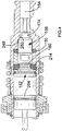
- Figure 6 shows the new design of beat piece 156 in accordance with the present invention. Where the same features in the first embodiment are shown in the prior art example described above, the same reference numbers are used. The only difference between the prior art design and the first embodiment is the design of the beat piece only.
- the rear section 176, first angled region 242 and middle section 172 of the beat piece 156 are the same as the prior art design and are circular in cross section in any plane which extends perpendicularly to the longitudinal axis 154 of the beat piece, the centre of each circular cross section being the longitudinal axis 154 of the beat piece 156.
- front section 174 and second angled region 248 has changed.
- the front section 174 and second angled region 248 are both still frusto conical in shape and circular in cross section in any plane which extends perpendicularly to the longitudinal axis 154 of the beat piece. However, the centre of each circular cross section is not the longitudinal axis 154 of the beat piece 156 but a second axis 300 which runs parallel to the longitudinal axis but is located in close proximity to the longitudinal axis. This results in the front section 174 and second angled region 248 being eccentric relative to the longitudinal axis of the beat piece.
- the second angled shoulder 250 formed on the inner wall of the spindle 150 is circular in cross section in any plane which extends perpendicularly from the longitudinal axis 154 of the spindle 150, the centre of the circular cross section being located on the longitudinal axis 154.
- the longitudinal axes 154 of the beat piece 156 and spindle 150 are co-axial. This results in the second axis 300 of the beat piece being off set relative to the longitudinal axis 154 of the spindle 150, resulting the front section 174 and second angled region being eccentric or off set relative to the longitudinal axis. This results in there being a non uniform amount of contact between the second angled region 248 and the second angled shoulder 250 around the longitudinal axis 154.
- the beat piece 156 twisting slightly as it rebounds backwards, increasing the frictional contact between the beat piece 156 and beat piece support structure.
- the beat piece either has insufficient force to travel rearwardly enough to engage the ram 152 or engages the ram with insufficient force to disengage it from the ram catcher.
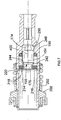
- FIG. 7 shows the new design of spindle 150 in accordance with the present invention. Where the same features in the prior art description described previously are present in the second embodiment, the same reference numbers are used. The only difference between the prior art design and the second embodiment is the design of the spindle only.
- the second angled shoulder 250 formed on the inner wall of the spindle 150 is circular in cross section in any plane which extends perpendicularly from the longitudinal axis 154 of the spindle 150.
- the centre of the circular cross sections is not located on the longitudinal axis 154 but on a third axis 400 which runs parallel to the longitudinal axis 154 but is located in close proximity to the longitudinal axis.
- the beat piece remains the same design as the prior art design. This results in there being a non uniform amount of contact between the second angled region and the second angled shoulder around the longitudinal axis 154.
- the beat piece 156 twisting slightly as it rebounds backwards, increasing the frictional contact between the beat piece and beat piece support structure.
- the beat piece either has insufficient force to travel rearwardly enough to engage with the ram 152 or engages the ram with insufficient force to disengage it from the ram catcher.
- both the second angled region (248) and the second angled shoulder (250) could be circular in cross section in any plane which extends perpendicularly from the longitudinal axis 154 of the spindle 150, but which are centred on axes which run parallel to the longitudinal axis, resulting in both the second angled region and the second angled shoulder being eccentric relative to the longitudinal axis 154 of the spindle 150.
Landscapes
- Engineering & Computer Science (AREA)
- Mechanical Engineering (AREA)
- Percussive Tools And Related Accessories (AREA)
Applications Claiming Priority (2)
| Application Number | Priority Date | Filing Date | Title |
|---|---|---|---|
| GBGB1112829.5A GB201112829D0 (en) | 2011-07-26 | 2011-07-26 | Hammer |
| EP12176722.2A EP2551062B1 (de) | 2011-07-26 | 2012-07-17 | Hammer |
Related Parent Applications (2)
| Application Number | Title | Priority Date | Filing Date |
|---|---|---|---|
| EP12176722.2A Division EP2551062B1 (de) | 2011-07-26 | 2012-07-17 | Hammer |
| EP12176722.2A Division-Into EP2551062B1 (de) | 2011-07-26 | 2012-07-17 | Hammer |
Publications (2)
| Publication Number | Publication Date |
|---|---|
| EP3260241A1 true EP3260241A1 (de) | 2017-12-27 |
| EP3260241B1 EP3260241B1 (de) | 2020-09-23 |
Family
ID=44652329
Family Applications (2)
| Application Number | Title | Priority Date | Filing Date |
|---|---|---|---|
| EP17181499.9A Active EP3260241B1 (de) | 2011-07-26 | 2012-07-17 | Hammer |
| EP12176722.2A Active EP2551062B1 (de) | 2011-07-26 | 2012-07-17 | Hammer |
Family Applications After (1)
| Application Number | Title | Priority Date | Filing Date |
|---|---|---|---|
| EP12176722.2A Active EP2551062B1 (de) | 2011-07-26 | 2012-07-17 | Hammer |
Country Status (3)
| Country | Link |
|---|---|
| US (1) | US9339924B2 (de) |
| EP (2) | EP3260241B1 (de) |
| GB (1) | GB201112829D0 (de) |
Families Citing this family (14)
| Publication number | Priority date | Publication date | Assignee | Title |
|---|---|---|---|---|
| JP1505300S (de) * | 2013-07-05 | 2015-11-09 | ||
| JP1519187S (de) * | 2013-11-18 | 2015-03-16 | ||
| EP3381619B1 (de) * | 2015-11-26 | 2022-11-30 | Koki Holdings Co., Ltd. | Hin- und hergehende arbeitsmaschine |
| USD830808S1 (en) * | 2016-11-14 | 2018-10-16 | Hilti Aktiengesellschaft | Breaker |
| USD843189S1 (en) * | 2016-12-20 | 2019-03-19 | Hilti Aktiengesellschaft | Breaker |
| USD843190S1 (en) * | 2016-12-20 | 2019-03-19 | Hilti Aktiengesellschaft | Combi hammer |
| FR3070290B1 (fr) * | 2017-08-22 | 2020-02-21 | Illinois Tool Works Inc | Outil de percage et son utilisation pour une operation de vissage |
| WO2019079560A1 (en) | 2017-10-20 | 2019-04-25 | Milwaukee Electric Tool Corporation | PERCUSSION TOOL |
| US11059155B2 (en) | 2018-01-26 | 2021-07-13 | Milwaukee Electric Tool Corporation | Percussion tool |
| EP3670096A1 (de) | 2018-12-21 | 2020-06-24 | Hilti Aktiengesellschaft | Handwerkzeugmaschine |
| EP3670097A1 (de) * | 2018-12-21 | 2020-06-24 | Hilti Aktiengesellschaft | Handwerkzeugmaschine |
| US11400577B2 (en) | 2019-06-11 | 2022-08-02 | Makita Corporation | Impact tool |
| JP7258665B2 (ja) * | 2019-06-11 | 2023-04-17 | 株式会社マキタ | 打撃工具 |
| GB201916665D0 (en) * | 2019-11-15 | 2020-01-01 | Black & Decker Inc | Piston |
Citations (4)
| Publication number | Priority date | Publication date | Assignee | Title |
|---|---|---|---|---|
| DE3526162A1 (de) * | 1985-07-22 | 1987-01-22 | Black & Decker Inc | Bohrhammer sowie bohrhammerwerkzeug |
| EP1157788A2 (de) * | 2000-04-07 | 2001-11-28 | Black & Decker Inc. | Mechanismus zur Betriebsartumschaltung für Bohrhammer |
| WO2007061101A1 (ja) * | 2005-11-28 | 2007-05-31 | Makita Corporation | 衝撃式作業工具 |
| WO2007141080A1 (de) * | 2006-06-06 | 2007-12-13 | Robert Bosch Gmbh | Schlagwerk mit einem schlagbolzen und einer zugeordneten fangvorrichtung |
Family Cites Families (9)
| Publication number | Priority date | Publication date | Assignee | Title |
|---|---|---|---|---|
| DE2444899C2 (de) * | 1974-09-19 | 1984-08-16 | Hilti Ag, Schaan | Bohrwerkzeug mit Bohrer und Aufnahmeteil |
| EP0272209B1 (de) * | 1986-12-17 | 1991-10-02 | HILTI Aktiengesellschaft | Handgerät |
| DE19929183B4 (de) * | 1999-06-25 | 2004-07-29 | Wacker Construction Equipment Ag | Luftfederschlagwerk mit Hohl-Schlagkolben mit Leerlauföffnung |
| DE102005000042A1 (de) | 2005-04-25 | 2006-10-26 | Hilti Ag | Bohr-oder Meisselhammer |
| DE102005019710A1 (de) * | 2005-04-28 | 2006-11-09 | Robert Bosch Gmbh | Handwerkzeugmaschinenschlagwerkeinheit |
| DE102005019711A1 (de) * | 2005-04-28 | 2006-11-09 | Robert Bosch Gmbh | Handwerkzeugmaschinenschlagwerkeinheit |
| DE102008022454B4 (de) | 2008-05-08 | 2014-06-26 | Aeg Electric Tools Gmbh | Bohrhammer |
| DE102010029915A1 (de) * | 2010-06-10 | 2011-12-15 | Hilti Aktiengesellschaft | Werkzeugmaschine und Steuerungsverfahren |
| DE102010062094A1 (de) * | 2010-11-29 | 2012-05-31 | Robert Bosch Gmbh | Hammerschlagwerk |
-
2011
- 2011-07-26 GB GBGB1112829.5A patent/GB201112829D0/en not_active Ceased
-
2012
- 2012-07-17 EP EP17181499.9A patent/EP3260241B1/de active Active
- 2012-07-17 EP EP12176722.2A patent/EP2551062B1/de active Active
- 2012-07-23 US US13/555,526 patent/US9339924B2/en active Active
Patent Citations (4)
| Publication number | Priority date | Publication date | Assignee | Title |
|---|---|---|---|---|
| DE3526162A1 (de) * | 1985-07-22 | 1987-01-22 | Black & Decker Inc | Bohrhammer sowie bohrhammerwerkzeug |
| EP1157788A2 (de) * | 2000-04-07 | 2001-11-28 | Black & Decker Inc. | Mechanismus zur Betriebsartumschaltung für Bohrhammer |
| WO2007061101A1 (ja) * | 2005-11-28 | 2007-05-31 | Makita Corporation | 衝撃式作業工具 |
| WO2007141080A1 (de) * | 2006-06-06 | 2007-12-13 | Robert Bosch Gmbh | Schlagwerk mit einem schlagbolzen und einer zugeordneten fangvorrichtung |
Also Published As
| Publication number | Publication date |
|---|---|
| GB201112829D0 (en) | 2011-09-07 |
| EP2551062A1 (de) | 2013-01-30 |
| EP2551062B1 (de) | 2019-04-17 |
| US20130025895A1 (en) | 2013-01-31 |
| US9339924B2 (en) | 2016-05-17 |
| EP3260241B1 (de) | 2020-09-23 |
Similar Documents
| Publication | Publication Date | Title |
|---|---|---|
| EP3260241B1 (de) | Hammer | |
| US7350592B2 (en) | Hammer drill with camming hammer drive mechanism | |
| US20170106517A1 (en) | Impact tool | |
| EP1825963B1 (de) | Schlagendes Handwerkzeuggerät | |
| EP1832393A2 (de) | Werkzeugmaschine | |
| EP3213876B1 (de) | Schlagvorrichtung | |
| EP3822038B1 (de) | Bohrhammer | |
| EP3683021B1 (de) | Bohrhammer | |
| US20200223048A1 (en) | Hammer drill | |
| EP2732924B1 (de) | Schlagwerkzeug | |
| WO2015045734A1 (ja) | 打撃工具 | |
| CN105939820B (zh) | 凿削的手持式工具机 | |
| JP7222703B2 (ja) | 打撃工具 | |
| US20240269815A1 (en) | Con rod | |
| JP2012223870A (ja) | 打撃工具 | |
| CN111823194B (zh) | 冲击工具 | |
| JP2009241228A (ja) | 打撃工具 | |
| WO2008062851A1 (en) | Percussion tool | |
| JP7338460B2 (ja) | 打撃作業機 | |
| CN213673949U (zh) | 冲击工具 | |
| JP5455159B2 (ja) | 打撃工具 |
Legal Events
| Date | Code | Title | Description |
|---|---|---|---|
| PUAI | Public reference made under article 153(3) epc to a published international application that has entered the european phase |
Free format text: ORIGINAL CODE: 0009012 |
|
| STAA | Information on the status of an ep patent application or granted ep patent |
Free format text: STATUS: THE APPLICATION HAS BEEN PUBLISHED |
|
| AC | Divisional application: reference to earlier application |
Ref document number: 2551062 Country of ref document: EP Kind code of ref document: P |
|
| AK | Designated contracting states |
Kind code of ref document: A1 Designated state(s): AL AT BE BG CH CY CZ DE DK EE ES FI FR GB GR HR HU IE IS IT LI LT LU LV MC MK MT NL NO PL PT RO RS SE SI SK SM TR |
|
| STAA | Information on the status of an ep patent application or granted ep patent |
Free format text: STATUS: REQUEST FOR EXAMINATION WAS MADE |
|
| 17P | Request for examination filed |
Effective date: 20180516 |
|
| RBV | Designated contracting states (corrected) |
Designated state(s): AL AT BE BG CH CY CZ DE DK EE ES FI FR GB GR HR HU IE IS IT LI LT LU LV MC MK MT NL NO PL PT RO RS SE SI SK SM TR |
|
| GRAP | Despatch of communication of intention to grant a patent |
Free format text: ORIGINAL CODE: EPIDOSNIGR1 |
|
| STAA | Information on the status of an ep patent application or granted ep patent |
Free format text: STATUS: GRANT OF PATENT IS INTENDED |
|
| INTG | Intention to grant announced |
Effective date: 20200430 |
|
| GRAS | Grant fee paid |
Free format text: ORIGINAL CODE: EPIDOSNIGR3 |
|
| GRAA | (expected) grant |
Free format text: ORIGINAL CODE: 0009210 |
|
| STAA | Information on the status of an ep patent application or granted ep patent |
Free format text: STATUS: THE PATENT HAS BEEN GRANTED |
|
| AC | Divisional application: reference to earlier application |
Ref document number: 2551062 Country of ref document: EP Kind code of ref document: P |
|
| AK | Designated contracting states |
Kind code of ref document: B1 Designated state(s): AL AT BE BG CH CY CZ DE DK EE ES FI FR GB GR HR HU IE IS IT LI LT LU LV MC MK MT NL NO PL PT RO RS SE SI SK SM TR |
|
| REG | Reference to a national code |
Ref country code: GB Ref legal event code: FG4D |
|
| REG | Reference to a national code |
Ref country code: CH Ref legal event code: EP |
|
| REG | Reference to a national code |
Ref country code: DE Ref legal event code: R096 Ref document number: 602012072521 Country of ref document: DE |
|
| REG | Reference to a national code |
Ref country code: IE Ref legal event code: FG4D |
|
| REG | Reference to a national code |
Ref country code: AT Ref legal event code: REF Ref document number: 1315916 Country of ref document: AT Kind code of ref document: T Effective date: 20201015 |
|
| PG25 | Lapsed in a contracting state [announced via postgrant information from national office to epo] |
Ref country code: BG Free format text: LAPSE BECAUSE OF FAILURE TO SUBMIT A TRANSLATION OF THE DESCRIPTION OR TO PAY THE FEE WITHIN THE PRESCRIBED TIME-LIMIT Effective date: 20201223 Ref country code: SE Free format text: LAPSE BECAUSE OF FAILURE TO SUBMIT A TRANSLATION OF THE DESCRIPTION OR TO PAY THE FEE WITHIN THE PRESCRIBED TIME-LIMIT Effective date: 20200923 Ref country code: NO Free format text: LAPSE BECAUSE OF FAILURE TO SUBMIT A TRANSLATION OF THE DESCRIPTION OR TO PAY THE FEE WITHIN THE PRESCRIBED TIME-LIMIT Effective date: 20201223 Ref country code: HR Free format text: LAPSE BECAUSE OF FAILURE TO SUBMIT A TRANSLATION OF THE DESCRIPTION OR TO PAY THE FEE WITHIN THE PRESCRIBED TIME-LIMIT Effective date: 20200923 Ref country code: GR Free format text: LAPSE BECAUSE OF FAILURE TO SUBMIT A TRANSLATION OF THE DESCRIPTION OR TO PAY THE FEE WITHIN THE PRESCRIBED TIME-LIMIT Effective date: 20201224 Ref country code: FI Free format text: LAPSE BECAUSE OF FAILURE TO SUBMIT A TRANSLATION OF THE DESCRIPTION OR TO PAY THE FEE WITHIN THE PRESCRIBED TIME-LIMIT Effective date: 20200923 |
|
| REG | Reference to a national code |
Ref country code: AT Ref legal event code: MK05 Ref document number: 1315916 Country of ref document: AT Kind code of ref document: T Effective date: 20200923 |
|
| PG25 | Lapsed in a contracting state [announced via postgrant information from national office to epo] |
Ref country code: RS Free format text: LAPSE BECAUSE OF FAILURE TO SUBMIT A TRANSLATION OF THE DESCRIPTION OR TO PAY THE FEE WITHIN THE PRESCRIBED TIME-LIMIT Effective date: 20200923 Ref country code: LV Free format text: LAPSE BECAUSE OF FAILURE TO SUBMIT A TRANSLATION OF THE DESCRIPTION OR TO PAY THE FEE WITHIN THE PRESCRIBED TIME-LIMIT Effective date: 20200923 |
|
| REG | Reference to a national code |
Ref country code: NL Ref legal event code: MP Effective date: 20200923 |
|
| REG | Reference to a national code |
Ref country code: LT Ref legal event code: MG4D |
|
| PG25 | Lapsed in a contracting state [announced via postgrant information from national office to epo] |
Ref country code: LT Free format text: LAPSE BECAUSE OF FAILURE TO SUBMIT A TRANSLATION OF THE DESCRIPTION OR TO PAY THE FEE WITHIN THE PRESCRIBED TIME-LIMIT Effective date: 20200923 Ref country code: CZ Free format text: LAPSE BECAUSE OF FAILURE TO SUBMIT A TRANSLATION OF THE DESCRIPTION OR TO PAY THE FEE WITHIN THE PRESCRIBED TIME-LIMIT Effective date: 20200923 Ref country code: PT Free format text: LAPSE BECAUSE OF FAILURE TO SUBMIT A TRANSLATION OF THE DESCRIPTION OR TO PAY THE FEE WITHIN THE PRESCRIBED TIME-LIMIT Effective date: 20210125 Ref country code: RO Free format text: LAPSE BECAUSE OF FAILURE TO SUBMIT A TRANSLATION OF THE DESCRIPTION OR TO PAY THE FEE WITHIN THE PRESCRIBED TIME-LIMIT Effective date: 20200923 Ref country code: SM Free format text: LAPSE BECAUSE OF FAILURE TO SUBMIT A TRANSLATION OF THE DESCRIPTION OR TO PAY THE FEE WITHIN THE PRESCRIBED TIME-LIMIT Effective date: 20200923 Ref country code: EE Free format text: LAPSE BECAUSE OF FAILURE TO SUBMIT A TRANSLATION OF THE DESCRIPTION OR TO PAY THE FEE WITHIN THE PRESCRIBED TIME-LIMIT Effective date: 20200923 |
|
| PG25 | Lapsed in a contracting state [announced via postgrant information from national office to epo] |
Ref country code: AT Free format text: LAPSE BECAUSE OF FAILURE TO SUBMIT A TRANSLATION OF THE DESCRIPTION OR TO PAY THE FEE WITHIN THE PRESCRIBED TIME-LIMIT Effective date: 20200923 Ref country code: AL Free format text: LAPSE BECAUSE OF FAILURE TO SUBMIT A TRANSLATION OF THE DESCRIPTION OR TO PAY THE FEE WITHIN THE PRESCRIBED TIME-LIMIT Effective date: 20200923 Ref country code: ES Free format text: LAPSE BECAUSE OF FAILURE TO SUBMIT A TRANSLATION OF THE DESCRIPTION OR TO PAY THE FEE WITHIN THE PRESCRIBED TIME-LIMIT Effective date: 20200923 Ref country code: IS Free format text: LAPSE BECAUSE OF FAILURE TO SUBMIT A TRANSLATION OF THE DESCRIPTION OR TO PAY THE FEE WITHIN THE PRESCRIBED TIME-LIMIT Effective date: 20210123 Ref country code: PL Free format text: LAPSE BECAUSE OF FAILURE TO SUBMIT A TRANSLATION OF THE DESCRIPTION OR TO PAY THE FEE WITHIN THE PRESCRIBED TIME-LIMIT Effective date: 20200923 |
|
| REG | Reference to a national code |
Ref country code: DE Ref legal event code: R097 Ref document number: 602012072521 Country of ref document: DE |
|
| PG25 | Lapsed in a contracting state [announced via postgrant information from national office to epo] |
Ref country code: SK Free format text: LAPSE BECAUSE OF FAILURE TO SUBMIT A TRANSLATION OF THE DESCRIPTION OR TO PAY THE FEE WITHIN THE PRESCRIBED TIME-LIMIT Effective date: 20200923 |
|
| PLBE | No opposition filed within time limit |
Free format text: ORIGINAL CODE: 0009261 |
|
| STAA | Information on the status of an ep patent application or granted ep patent |
Free format text: STATUS: NO OPPOSITION FILED WITHIN TIME LIMIT |
|
| PG25 | Lapsed in a contracting state [announced via postgrant information from national office to epo] |
Ref country code: SI Free format text: LAPSE BECAUSE OF FAILURE TO SUBMIT A TRANSLATION OF THE DESCRIPTION OR TO PAY THE FEE WITHIN THE PRESCRIBED TIME-LIMIT Effective date: 20200923 Ref country code: DK Free format text: LAPSE BECAUSE OF FAILURE TO SUBMIT A TRANSLATION OF THE DESCRIPTION OR TO PAY THE FEE WITHIN THE PRESCRIBED TIME-LIMIT Effective date: 20200923 |
|
| 26N | No opposition filed |
Effective date: 20210624 |
|
| PG25 | Lapsed in a contracting state [announced via postgrant information from national office to epo] |
Ref country code: IT Free format text: LAPSE BECAUSE OF FAILURE TO SUBMIT A TRANSLATION OF THE DESCRIPTION OR TO PAY THE FEE WITHIN THE PRESCRIBED TIME-LIMIT Effective date: 20200923 |
|
| REG | Reference to a national code |
Ref country code: CH Ref legal event code: PL |
|
| PG25 | Lapsed in a contracting state [announced via postgrant information from national office to epo] |
Ref country code: MC Free format text: LAPSE BECAUSE OF FAILURE TO SUBMIT A TRANSLATION OF THE DESCRIPTION OR TO PAY THE FEE WITHIN THE PRESCRIBED TIME-LIMIT Effective date: 20200923 |
|
| REG | Reference to a national code |
Ref country code: BE Ref legal event code: MM Effective date: 20210731 |
|
| PG25 | Lapsed in a contracting state [announced via postgrant information from national office to epo] |
Ref country code: LI Free format text: LAPSE BECAUSE OF NON-PAYMENT OF DUE FEES Effective date: 20210731 Ref country code: CH Free format text: LAPSE BECAUSE OF NON-PAYMENT OF DUE FEES Effective date: 20210731 |
|
| PG25 | Lapsed in a contracting state [announced via postgrant information from national office to epo] |
Ref country code: LU Free format text: LAPSE BECAUSE OF NON-PAYMENT OF DUE FEES Effective date: 20210717 Ref country code: FR Free format text: LAPSE BECAUSE OF NON-PAYMENT OF DUE FEES Effective date: 20210731 |
|
| PG25 | Lapsed in a contracting state [announced via postgrant information from national office to epo] |
Ref country code: IE Free format text: LAPSE BECAUSE OF NON-PAYMENT OF DUE FEES Effective date: 20210717 Ref country code: BE Free format text: LAPSE BECAUSE OF NON-PAYMENT OF DUE FEES Effective date: 20210731 |
|
| PG25 | Lapsed in a contracting state [announced via postgrant information from national office to epo] |
Ref country code: HU Free format text: LAPSE BECAUSE OF FAILURE TO SUBMIT A TRANSLATION OF THE DESCRIPTION OR TO PAY THE FEE WITHIN THE PRESCRIBED TIME-LIMIT; INVALID AB INITIO Effective date: 20120717 Ref country code: CY Free format text: LAPSE BECAUSE OF FAILURE TO SUBMIT A TRANSLATION OF THE DESCRIPTION OR TO PAY THE FEE WITHIN THE PRESCRIBED TIME-LIMIT Effective date: 20200923 |
|
| PG25 | Lapsed in a contracting state [announced via postgrant information from national office to epo] |
Ref country code: NL Free format text: LAPSE BECAUSE OF NON-PAYMENT OF DUE FEES Effective date: 20200923 |
|
| PG25 | Lapsed in a contracting state [announced via postgrant information from national office to epo] |
Ref country code: MK Free format text: LAPSE BECAUSE OF FAILURE TO SUBMIT A TRANSLATION OF THE DESCRIPTION OR TO PAY THE FEE WITHIN THE PRESCRIBED TIME-LIMIT Effective date: 20200923 |
|
| PG25 | Lapsed in a contracting state [announced via postgrant information from national office to epo] |
Ref country code: MT Free format text: LAPSE BECAUSE OF FAILURE TO SUBMIT A TRANSLATION OF THE DESCRIPTION OR TO PAY THE FEE WITHIN THE PRESCRIBED TIME-LIMIT Effective date: 20200923 |
|
| PGFP | Annual fee paid to national office [announced via postgrant information from national office to epo] |
Ref country code: DE Payment date: 20250722 Year of fee payment: 14 |
|
| PGFP | Annual fee paid to national office [announced via postgrant information from national office to epo] |
Ref country code: GB Payment date: 20250724 Year of fee payment: 14 |
|
| PG25 | Lapsed in a contracting state [announced via postgrant information from national office to epo] |
Ref country code: TR Free format text: LAPSE BECAUSE OF FAILURE TO SUBMIT A TRANSLATION OF THE DESCRIPTION OR TO PAY THE FEE WITHIN THE PRESCRIBED TIME-LIMIT Effective date: 20200923 |