EP3260247A1 - Werkzeug zur platzierung von objekten - Google Patents
Werkzeug zur platzierung von objekten Download PDFInfo
- Publication number
- EP3260247A1 EP3260247A1 EP16176004.6A EP16176004A EP3260247A1 EP 3260247 A1 EP3260247 A1 EP 3260247A1 EP 16176004 A EP16176004 A EP 16176004A EP 3260247 A1 EP3260247 A1 EP 3260247A1
- Authority
- EP
- European Patent Office
- Prior art keywords
- tool
- legs
- gripping
- vibration
- tile
- Prior art date
- Legal status (The legal status is an assumption and is not a legal conclusion. Google has not performed a legal analysis and makes no representation as to the accuracy of the status listed.)
- Granted
Links
Images


Classifications
-
- B—PERFORMING OPERATIONS; TRANSPORTING
- B25—HAND TOOLS; PORTABLE POWER-DRIVEN TOOLS; MANIPULATORS
- B25J—MANIPULATORS; CHAMBERS PROVIDED WITH MANIPULATION DEVICES
- B25J15/00—Gripping heads and other end effectors
- B25J15/06—Gripping heads and other end effectors with vacuum or magnetic holding means
- B25J15/0616—Gripping heads and other end effectors with vacuum or magnetic holding means with vacuum
-
- E—FIXED CONSTRUCTIONS
- E04—BUILDING
- E04F—FINISHING WORK ON BUILDINGS, e.g. STAIRS, FLOORS
- E04F21/00—Implements for finishing work on buildings
- E04F21/20—Implements for finishing work on buildings for laying flooring
- E04F21/22—Implements for finishing work on buildings for laying flooring of single elements, e.g. flooring cramps ; flexible webs
Definitions
- the present document relates to a tool for placing objects on a surface and to a method of operating said tool.
- US 2015/0336272 A1 discloses a machine for aligning items in a pattern and a method of using the machine.
- the machine includes an effector for positioning the items as well as several edge and height sensors.
- the sensors are used for positioning a new item such as a tile in x, y and z directions relative to a first and second laid tile.
- the machine includes one or more suction cups connected to a vacuum source for picking up, positioning and releasing an item relative to a first laid item and a second laid item.
- EP 2907938 A1 describes an apparatus and method for placing a tile on a floor.
- the apparatus includes a measuring device configured to measure the position of a tile to be placed on the floor relative to the ones which are already put in place.
- the apparatus comprises a holding head arranged on a lower portion of a positioning device for holding a tile.
- the holding head comprises a vacuum cup for holding the tile and is movable in six degrees of freedom.
- placing an object depending only on the position of previously positioned objects may give rise to initially small inaccuracies which will accumulate and thus grow larger for each placed object, and further to this placing an object, such as a tile, in a bonding material requires great accuracy and just the right amount of force applied to the tile.
- a tool for placing at least one object on a surface wherein the tool has a first portion for gripping and releasing said object and a second portion adapted to be attached to a moveable system
- the tool comprises at least three individually controllable tool legs, wherein each tool leg is provided with a gripping device at a lower portion thereof, a rotation device, wherein the tool legs are attached to a base portion of the rotation device, at least one vibration device, wherein said tool legs are arranged to surround said at least one vibration device, and wherein said rotation device is arranged to be able to simultaneously rotate the at least three tool legs around a center of rotation of the object the tool is arranged to hold.
- a tool for placing objects such as for instance floor tiles
- the tool has tool legs with gripping devices for holding an object, surrounding a vibration device
- the placement of the tool legs allow for the tool to pick up and hold an object, such as a square tile at the four corners thereof. This allows for a very exact positioning of the object.
- the rotational device thus allows for the object, such as a tile, to be placed with an even gap width in relation to a juxtaposed object.
- the tool may have to be equipped with more than one vibration device.
- the vibration device may for instance be placed in connection with each tool leg. To ensure the robustness and compactness the vibration device will, however always be placed within the tool legs.
- the lower portion of the tool legs may be moveable in a direction which is perpendicular to an upper surface of said object, said gripping device may thus be moveable in four degrees of freedom.
- the tool and the rotation device creates a system having six degrees of freedom. Without the traveler system the tool creates four degrees of freedom for the moving the object. This allows for placing the object, or tile, in a very exact manner.
- the movable system may be any one of a traveler system and a robotic system.
- robotic system for instance a jointed robotic arm.
- the gripping device may comprise a suction device, such as a suction cup.
- Each of said gripping devices may individually controllable. This means that they allows for the tool to provide four degrees of freedom when handling the object.
- the vibration device comprises a lower portion having a substantially flat surface, or a vibration plate, for abutting said upper surface of the object, and a vibrator, wherein said lower portion is connected to the base portion of the rotation device.
- the flat surface thus acts as a vibration plate, conferring the vibration from the vibrator onto the object below.
- the vibrator may be any commercially available vibrator.
- the vibrator is connected to the vibration plate and thus impacts the object, conferring the vibration to the object through the vibration plate.
- the lower portion of the vibration device may be connected to the base portion by at least three connections rods.
- the vibration device may further comprise at least three biasing devices.
- the biasing devices or pressure devices are connected to the vibration plate through the connection rods, and are arranged to be able to move and hold the vibration device, i.e. the vibration plate onto the upper surface of the object.
- the biasing devices are further arranged to provide a pressure onto the upper surface of the object which is sufficient to provide a controlled vibration of the object by the vibrator. This vibration is sufficient to fluidize the medium, such as mortar, underlying the object, such as a tile, such that the object is fixated onto the surface.
- the gripping devices are arranged to grip and hold said object on an upper surface thereof and to release said object onto a surface opposite said upper surface of the object.
- the object may be any one of a ceramic tile, a vinyl tile, a plastic tile, a stone tile, bricks, roof shingles, roof panels and wall panels.
- a method for operating the tool comprises the steps of, gripping an object by said gripping devices; adjusting and aligning the position of said object in relation to at least a second object placed on a surface by controlling said rotating device and/or said tool legs; placing said object juxtaposed to said at least one second object on said surface by controlling said tool legs, measuring the height of the object in relation to the juxtaposed object or objects, abutting a vibration device onto an upper surface of the object; and applying a tool pressure and vibration to said object by said vibration device until the height of the object in relation to the juxtaposed object or objects is correct and releasing said object by said gripping device, when said object is in a correct position and height in relation to said juxtaposed object or objects.
- This method requires that a measuring system for determining the correct position and height is used in connection with the tool and machine.
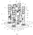
- Fig. 1 illustrates a tool 1, and the tool holds or grips an object 2.
- the object 2 may be a tile such as a ceramic tile, vinyl tile, plastic tile, stone tile, bricks, roof shingles, roof panels, wall panels, tiles composed of different materials etc.
- the object may have any suitable size and shape, but it is most commonly a rectangular or square tile, having a size in the range of 100x100 mm to 800x800 mm. Rectangular shaped tiles may also vary in size and dimensions.
- the object may also have other geometrical shapes as triangular or round.
- the objects may also vary in height, and generally have a height in the range of 5 to 60 mm.
- the above mentioned sizes of the objects are not meant to limit the scope of tiles that the tool can carry and position.
- the tool can be constructed such that it can carry virtually any size and/or weight of the object. On advantage with the present tool is that it is able to handle both relatively thin and light objects as well as relatively big, thick and heavy objects.
- the tool 1 may be placed in a machine, not shown in the drawings, comprising a moving system, such as the illustrated traveler or a trolley system 30, 31, 32 in Fig. 6 .
- the moving system allows for the tool to pick up an object for instance from a stack or pile of objects and move the object to a correct position on a surface, without a user having to move or handle the machine.
- a second or upper portion 4 of the tool 1 is arranged to be attached to a traveler or a trolley system 30, 31, 32.
- the machine may further comprise a measuring system, control devices and a user interface.
- the control devices may include a computer, hardware and software.
- a measuring system comprising a number of sensors and control devices, not shown in the drawings or described further below, arranged to determine the position of both the tool 1 and the object 2 for positioning, aligning and placing the object at the correct position.
- the construction and shape of the tool allow for the measuring system to have the best possible view of the tool, tool part and object.
- the sensors may include optical sensors, such as laser, photovoltaic cells, or an optical camera and video camera, both analogue and digital.
- the tool has a lower portion 3, comprising gripping devices 6 for holding and releasing the object 2.
- the gripping device 6 may be for a suction device such as suction cup, and each of the gripping devices 6 may be individually controllable and adjusted.
- the gripping devices are arranged on tool legs 5.
- the tool 1 comprises at least three tool legs 5.
- a tool 1 having three tool legs may be used for instance when gripping a triangle shaped object.
- the tool legs 5 are attached to a rotation or rotating device 10.
- the rotating device 10 is arranged be able to rotate around a center of rotation of the object is holding.
- the rotation device 10 is placed symmetrically and centrally in relation to the tool legs 5.
- the at least three tool legs 5 are arranged to surround a vibration device 9, i.e. the vibration device is arranged within the circumference all of the tool legs present in the tool at all times.
- the tool legs are further arranged and positioned such that an optimal grip of the object is achieved.
- optimal grip of the object is meant that the gripping devices 6 are placed as close as possible to the corners of the object, while allowing for the measuring system to be able to determine where the edges of the object are located.
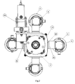
- a tool 1 is shown having four tool legs, where the distance between the tool legs 5 is designed such that the distances between the legs is equal, i.e. as seen in a top view of the tool 1 in Fig. 2 the four legs may be arranged at an angle of 90° to each other, in relation to a central axis of said vibration device. This position of the tool legs 5 is advantageous for a square object or tile.
- the tool 1 may alternatively comprise even more than four tool legs.
- the tool legs 5 have a gripping device 6 arranged at a lower portion 7 thereof.
- lower portion 7 of the leg is meant the portion of the tool leg that is to be or is in proximity to the object 2 to be carried.
- the tool leg 5 may be attached to a base portion 14 of the rotation device 10 by a connection 22.
- the tool leg may thus be attached to the rotating device 10, such that it can be removed for repairs etc. if needed.
- the tool leg 5 is provided with means for adjusting the vertical position of the lower portion 7 and gripping device 6, i.e. to enable adjustment of the height of the gripping devices when placing a tile on a floor surface. Since the gripping devices 6 are individually controllable for height, the object can be moveable in four degrees of freedom. By vertical position is meant that the gripping device 6 is moveable or adjustable in a direction D which is perpendicular to an upper surface 11 of the object 2.
- the means for adjusting the vertical position may be a pneumatic or hydraulic piston, or an electric motor, or any other means suitable for controlling the vertical position.
- the upper portion 8 of the tool leg 5 may house the control means.
- the gripping devices may be a suction cup.
- the suction cup may be formed from a material which is flexible enough to maintain the suction, i.e. the grip, of the upper surface of the object while the object is subjected to a vibration by the vibration device.
- Each tool leg 5 is further provided with a vacuum source 20 connected to a pressurized air source (not shown in the drawings).
- the lower portion 7 of the leg may thus be constructed such that a suction cup arranged thereon is in connection with a vacuum source.
- the gripping devices 6 are fixedly connected to the lower portion 7 of the tool leg.
- the rotation device 10 has a base portion 14.
- the connection 22 of tool legs 5 may be attached to the mating connection 23.
- the tool 1 is further provided with a vibration device 9.
- the vibration device is provided in order to set or fixate the object 2 properly on the surface where it is to be placed.
- the vibration device 9 is arranged to generate the vibration and transfer the vibration to the object 2, thus emulating the movement made by a craftsman when he knocks on a tile in order for the tile to set or fasten in the underlying medium such as mortar.
- This means that the vibration, or frequency of the vibration, and the downwardly directed force used by the vibration device will depend on the underlying material, and the desired height of the object in relation to a second object placed adjacent or juxtaposed to the object 2.
- the vibration movement may be a linear stroke or rotational stroke, depending on the equipment and configuration used.
- the vibration device is thus as such provided to fluidize the underlying medium or mortar, such that the object is properly fixated onto the surface.
- the tool 1 is supervised by sensors for determining and measuring the correct position and height of the object in relation to at least one other juxtaposed object placed on the surface, and thus to a control system for controlling the vibration device 9 through the operating device.
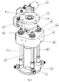
- the vibration device 9 comprises a lower portion 13, which comprises a flat surface, or a so called vibration plate 33.
- the vibration plate 33 is connected to the base portion 33 by at least three connection rods 25, which are suspended in the base portion 33.
- the lower portion 13 of the vibration device 9 may be constructed in various manners, depending on the object to which it is arranged to abut. As shown in Fig. 4 the lower portion 13 may comprises a flat surface 33 adapted for abutting an upper surface 11 of the object 2.
- the lower portion of the vibration plate may further be provided with a rubber plate etc..
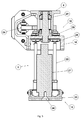
- the vibration device 9 further comprises a vibrator 27.
- the vibrator may be any commercially available vibrator for providing the vibration movement.
- the vibrator may be fixedly connected to the vibration plate, as shown in Fig. 5 by a screw joint 33.
- the vibration device further comprises at least three biasing devices 28 or pressure devices which are connected to the connection rods 25.
- the biasing devices 28 thus provides for a way of gripping, holding and placing the object in the correct position without the vibration plate 33 being in connection with the object. Once the object has been placed in a correct position in relation to a juxtaposed object, the biasing devices provides for the vibration plate being able to abut an upper surface of the object.
- the biasing devices 28 may then provide a tool pressure onto, i.e. press the vibration plate onto the upper surface of the object, which tool pressure is adapted to be sufficient for providing a controlled vibration.
- the biasing device 28 is shown as a pneumatic cylinder suspended in the base portion 14.
- the biasing devices may however be for instance a spring, such as a hydraulic or pneumatic spring or a coil spring.
- the biasing devices 28 may further be electromechanically controlled devices.
- the vibration device 9 may also be made to rotate around the center of rotation of the object 2.
- the vibration device 9 is connected to an operating device, not shown in the drawings, for providing the correct tool pressure and vibration movement onto an object 2.
- an engine or motor 24 is arranged to operate the rotation device 10.
- the engine or motor 24 may be a step motor having a through shaft, but it may alternatively be any type of suitable motor.
- the rotation device 10 may be operated by any other suitable drive means.
- the engine or motor 24 may be connected to an arm 26 that provides the rotational movement of the base portion 14, thus rotating the tool arms 5 and the vibration device 9.
- a ball bearing 29 may be provided inside the rotation device 10 to facilitate the rotational movement. Since the upper part 4 of the tool 1 is connected to a moveable system such as for instance a part 30 of traveler or trolley system 30, 31, 32 as illustrated by Fig. 6 the arm 26 connected to the engine 24 can provide for the rotational movement of the rotation device. This rotational movement may be provided in other ways as well.
- a moveably system is shown as a traveler system 30, 31, 32.
- This system allows for the movement of the tool 1 in several different directions, to grip, lift, align and place an object 2 on a surface, thus providing the gripping devices with a full six degrees of freedom when handling the object 2.
Landscapes
- Engineering & Computer Science (AREA)
- Architecture (AREA)
- Civil Engineering (AREA)
- Structural Engineering (AREA)
- Robotics (AREA)
- Mechanical Engineering (AREA)
- Manipulator (AREA)
Priority Applications (1)
| Application Number | Priority Date | Filing Date | Title |
|---|---|---|---|
| EP16176004.6A EP3260247B1 (de) | 2016-06-23 | 2016-06-23 | Werkzeug zur platzierung von objekten |
Applications Claiming Priority (1)
| Application Number | Priority Date | Filing Date | Title |
|---|---|---|---|
| EP16176004.6A EP3260247B1 (de) | 2016-06-23 | 2016-06-23 | Werkzeug zur platzierung von objekten |
Publications (2)
| Publication Number | Publication Date |
|---|---|
| EP3260247A1 true EP3260247A1 (de) | 2017-12-27 |
| EP3260247B1 EP3260247B1 (de) | 2020-12-23 |
Family
ID=56235672
Family Applications (1)
| Application Number | Title | Priority Date | Filing Date |
|---|---|---|---|
| EP16176004.6A Active EP3260247B1 (de) | 2016-06-23 | 2016-06-23 | Werkzeug zur platzierung von objekten |
Country Status (1)
| Country | Link |
|---|---|
| EP (1) | EP3260247B1 (de) |
Cited By (6)
| Publication number | Priority date | Publication date | Assignee | Title |
|---|---|---|---|---|
| CN108861576A (zh) * | 2018-08-03 | 2018-11-23 | 奇瑞万达贵州客车股份有限公司 | 一种钣金料板的吸盘手爪 |
| CN111335600A (zh) * | 2020-03-08 | 2020-06-26 | 大国重器自动化设 备(山东)股份有限公司 | 一种铺地砖机器人的控制方法、装置及其控制系统 |
| CN112523482A (zh) * | 2020-12-07 | 2021-03-19 | 常熟理工学院 | 基于干铺法的自动铺瓷砖车 |
| CN113733144A (zh) * | 2021-09-27 | 2021-12-03 | 北京中海兴达建设有限公司 | 一种建筑施工用工业机器人抓手 |
| CN115434492A (zh) * | 2022-10-21 | 2022-12-06 | 山东滨中建筑装饰集团有限公司 | 一种装饰装修施工用瓷砖铺贴机 |
| US12338082B2 (en) | 2020-04-03 | 2025-06-24 | Beumer Group A/S | Pick and place robot system, method, use and sorter system |
Citations (7)
| Publication number | Priority date | Publication date | Assignee | Title |
|---|---|---|---|---|
| DE20308251U1 (de) * | 2003-05-23 | 2003-07-31 | Schwab, Harry, 71083 Herrenberg | Vorrichtung zum Verdichten von Untergrund |
| EP1441069A1 (de) * | 2003-01-17 | 2004-07-28 | W.O.S. Systeem B.V. | Verfahren und Vorrichtung zum Einbetten von Platten in einem eine Art von Sand enthaltendes Substrat |
| CN102277955A (zh) * | 2011-05-13 | 2011-12-14 | 王怀成 | 智能铺砖机 |
| CN102808502A (zh) * | 2012-08-27 | 2012-12-05 | 维和泰隆(北京)科技有限公司 | 高效铺设建筑面层的自动化智能设备及其铺设方法 |
| CN104060808A (zh) * | 2014-02-13 | 2014-09-24 | 王越 | 全自动智能贴砖机 |
| EP2907938A1 (de) | 2014-02-18 | 2015-08-19 | IR-Eng.Limited | Vorrichtung und Verfahren zur Platzierung einer Platte auf einem Boden |
| US20150336272A1 (en) | 2014-04-25 | 2015-11-26 | Gary Lee Drew | Machine for aligning items in a pattern and a method of use |
-
2016
- 2016-06-23 EP EP16176004.6A patent/EP3260247B1/de active Active
Patent Citations (7)
| Publication number | Priority date | Publication date | Assignee | Title |
|---|---|---|---|---|
| EP1441069A1 (de) * | 2003-01-17 | 2004-07-28 | W.O.S. Systeem B.V. | Verfahren und Vorrichtung zum Einbetten von Platten in einem eine Art von Sand enthaltendes Substrat |
| DE20308251U1 (de) * | 2003-05-23 | 2003-07-31 | Schwab, Harry, 71083 Herrenberg | Vorrichtung zum Verdichten von Untergrund |
| CN102277955A (zh) * | 2011-05-13 | 2011-12-14 | 王怀成 | 智能铺砖机 |
| CN102808502A (zh) * | 2012-08-27 | 2012-12-05 | 维和泰隆(北京)科技有限公司 | 高效铺设建筑面层的自动化智能设备及其铺设方法 |
| CN104060808A (zh) * | 2014-02-13 | 2014-09-24 | 王越 | 全自动智能贴砖机 |
| EP2907938A1 (de) | 2014-02-18 | 2015-08-19 | IR-Eng.Limited | Vorrichtung und Verfahren zur Platzierung einer Platte auf einem Boden |
| US20150336272A1 (en) | 2014-04-25 | 2015-11-26 | Gary Lee Drew | Machine for aligning items in a pattern and a method of use |
Cited By (7)
| Publication number | Priority date | Publication date | Assignee | Title |
|---|---|---|---|---|
| CN108861576A (zh) * | 2018-08-03 | 2018-11-23 | 奇瑞万达贵州客车股份有限公司 | 一种钣金料板的吸盘手爪 |
| CN111335600A (zh) * | 2020-03-08 | 2020-06-26 | 大国重器自动化设 备(山东)股份有限公司 | 一种铺地砖机器人的控制方法、装置及其控制系统 |
| US12338082B2 (en) | 2020-04-03 | 2025-06-24 | Beumer Group A/S | Pick and place robot system, method, use and sorter system |
| CN112523482A (zh) * | 2020-12-07 | 2021-03-19 | 常熟理工学院 | 基于干铺法的自动铺瓷砖车 |
| CN113733144A (zh) * | 2021-09-27 | 2021-12-03 | 北京中海兴达建设有限公司 | 一种建筑施工用工业机器人抓手 |
| CN113733144B (zh) * | 2021-09-27 | 2022-09-16 | 菏泽城建工程发展集团有限公司 | 一种建筑施工用工业机器人抓手 |
| CN115434492A (zh) * | 2022-10-21 | 2022-12-06 | 山东滨中建筑装饰集团有限公司 | 一种装饰装修施工用瓷砖铺贴机 |
Also Published As
| Publication number | Publication date |
|---|---|
| EP3260247B1 (de) | 2020-12-23 |
Similar Documents
| Publication | Publication Date | Title |
|---|---|---|
| EP3260247B1 (de) | Werkzeug zur platzierung von objekten | |
| EP3519651B1 (de) | System zur platzierung von objekten auf einer oberfläche und verfahren dafür | |
| EP2907938A1 (de) | Vorrichtung und Verfahren zur Platzierung einer Platte auf einem Boden | |
| WO2015164449A1 (en) | A tile laying machine and a method of use | |
| US12385265B2 (en) | Block transfer apparatus and improved clamping assembly for use therewith | |
| WO2022116932A1 (zh) | 铺贴机器人、铺贴系统和铺贴方法 | |
| CN114043482A (zh) | 一种基于视觉识别操控的机械臂 | |
| WO2023010906A1 (zh) | 墙砖铺贴设备及墙砖铺贴方法 | |
| WO2022234752A1 (ja) | ピッキングシステム | |
| JP2020165265A (ja) | ボードパレット及びボードのピックアップ方法 | |
| CN110685427B (zh) | 一种数控铺砖机 | |
| CN115405077B (zh) | 高度调平执行装置以及地砖铺设方法 | |
| RU2754505C1 (ru) | Способ возведения конструкций из мелкоштучных изделий, робот-манипулятор и комплекс для его осуществления | |
| JP6394540B2 (ja) | コークス炉定型耐火物積み方法 | |
| CN215907321U (zh) | 一种用于铺砖机器人的机械臂 | |
| JPH07127270A (ja) | 建築部材位置決め装置 | |
| CA3096361C (en) | Methods and system for preparing and installing brick assemblies on the floor of an electrolysis cell | |
| CN112746729B (zh) | 瓷砖锤平装置及瓷砖锤平方法 | |
| US10919717B2 (en) | Lifting device for blocks with non-parallel walls | |
| CN112554517B (zh) | 瓷砖抓取装置 | |
| CN216974090U (zh) | 铺贴装置及铺贴设备 | |
| JP2003208227A (ja) | 構造物の位置決め装置および方法 | |
| CN117091939B (zh) | 一种水泥样件的姿态调整系统 | |
| CN114059750B (zh) | 地砖铺设装置及地砖铺设机器人 | |
| HK40081873A (en) | Wall tile paving apparatus and wall tile paving method |
Legal Events
| Date | Code | Title | Description |
|---|---|---|---|
| PUAI | Public reference made under article 153(3) epc to a published international application that has entered the european phase |
Free format text: ORIGINAL CODE: 0009012 |
|
| STAA | Information on the status of an ep patent application or granted ep patent |
Free format text: STATUS: THE APPLICATION HAS BEEN PUBLISHED |
|
| AK | Designated contracting states |
Kind code of ref document: A1 Designated state(s): AL AT BE BG CH CY CZ DE DK EE ES FI FR GB GR HR HU IE IS IT LI LT LU LV MC MK MT NL NO PL PT RO RS SE SI SK SM TR |
|
| AX | Request for extension of the european patent |
Extension state: BA ME |
|
| STAA | Information on the status of an ep patent application or granted ep patent |
Free format text: STATUS: THE APPLICATION IS DEEMED TO BE WITHDRAWN |
|
| 18D | Application deemed to be withdrawn |
Effective date: 20180628 |
|
| 19U | Interruption of proceedings before grant |
Effective date: 20180216 |
|
| 19W | Proceedings resumed before grant after interruption of proceedings |
Effective date: 20200102 |
|
| RAP1 | Party data changed (applicant data changed or rights of an application transferred) |
Owner name: EL-ZOUKI GROUP AB |
|
| 17P | Request for examination filed |
Effective date: 20200506 |
|
| RBV | Designated contracting states (corrected) |
Designated state(s): AL AT BE BG CH CY CZ DE DK EE ES FI FR GB GR HR HU IE IS IT LI LT LU LV MC MK MT NL NO PL PT RO RS SE SI SK SM TR |
|
| STAA | Information on the status of an ep patent application or granted ep patent |
Free format text: STATUS: REQUEST FOR EXAMINATION WAS MADE |
|
| D18D | Application deemed to be withdrawn (deleted) | ||
| GRAP | Despatch of communication of intention to grant a patent |
Free format text: ORIGINAL CODE: EPIDOSNIGR1 |
|
| STAA | Information on the status of an ep patent application or granted ep patent |
Free format text: STATUS: GRANT OF PATENT IS INTENDED |
|
| INTG | Intention to grant announced |
Effective date: 20200813 |
|
| GRAS | Grant fee paid |
Free format text: ORIGINAL CODE: EPIDOSNIGR3 |
|
| GRAA | (expected) grant |
Free format text: ORIGINAL CODE: 0009210 |
|
| STAA | Information on the status of an ep patent application or granted ep patent |
Free format text: STATUS: THE PATENT HAS BEEN GRANTED |
|
| AK | Designated contracting states |
Kind code of ref document: B1 Designated state(s): AL AT BE BG CH CY CZ DE DK EE ES FI FR GB GR HR HU IE IS IT LI LT LU LV MC MK MT NL NO PL PT RO RS SE SI SK SM TR |
|
| REG | Reference to a national code |
Ref country code: DE Ref legal event code: R096 Ref document number: 602016050130 Country of ref document: DE |
|
| REG | Reference to a national code |
Ref country code: AT Ref legal event code: REF Ref document number: 1347290 Country of ref document: AT Kind code of ref document: T Effective date: 20210115 |
|
| REG | Reference to a national code |
Ref country code: IE Ref legal event code: FG4D |
|
| REG | Reference to a national code |
Ref country code: SE Ref legal event code: TRGR |
|
| PG25 | Lapsed in a contracting state [announced via postgrant information from national office to epo] |
Ref country code: FI Free format text: LAPSE BECAUSE OF FAILURE TO SUBMIT A TRANSLATION OF THE DESCRIPTION OR TO PAY THE FEE WITHIN THE PRESCRIBED TIME-LIMIT Effective date: 20201223 Ref country code: GR Free format text: LAPSE BECAUSE OF FAILURE TO SUBMIT A TRANSLATION OF THE DESCRIPTION OR TO PAY THE FEE WITHIN THE PRESCRIBED TIME-LIMIT Effective date: 20210324 Ref country code: NO Free format text: LAPSE BECAUSE OF FAILURE TO SUBMIT A TRANSLATION OF THE DESCRIPTION OR TO PAY THE FEE WITHIN THE PRESCRIBED TIME-LIMIT Effective date: 20210323 Ref country code: RS Free format text: LAPSE BECAUSE OF FAILURE TO SUBMIT A TRANSLATION OF THE DESCRIPTION OR TO PAY THE FEE WITHIN THE PRESCRIBED TIME-LIMIT Effective date: 20201223 |
|
| REG | Reference to a national code |
Ref country code: AT Ref legal event code: MK05 Ref document number: 1347290 Country of ref document: AT Kind code of ref document: T Effective date: 20201223 |
|
| REG | Reference to a national code |
Ref country code: NL Ref legal event code: MP Effective date: 20201223 |
|
| PG25 | Lapsed in a contracting state [announced via postgrant information from national office to epo] |
Ref country code: BG Free format text: LAPSE BECAUSE OF FAILURE TO SUBMIT A TRANSLATION OF THE DESCRIPTION OR TO PAY THE FEE WITHIN THE PRESCRIBED TIME-LIMIT Effective date: 20210323 Ref country code: LV Free format text: LAPSE BECAUSE OF FAILURE TO SUBMIT A TRANSLATION OF THE DESCRIPTION OR TO PAY THE FEE WITHIN THE PRESCRIBED TIME-LIMIT Effective date: 20201223 |
|
| PG25 | Lapsed in a contracting state [announced via postgrant information from national office to epo] |
Ref country code: HR Free format text: LAPSE BECAUSE OF FAILURE TO SUBMIT A TRANSLATION OF THE DESCRIPTION OR TO PAY THE FEE WITHIN THE PRESCRIBED TIME-LIMIT Effective date: 20201223 Ref country code: NL Free format text: LAPSE BECAUSE OF FAILURE TO SUBMIT A TRANSLATION OF THE DESCRIPTION OR TO PAY THE FEE WITHIN THE PRESCRIBED TIME-LIMIT Effective date: 20201223 |
|
| REG | Reference to a national code |
Ref country code: LT Ref legal event code: MG9D |
|
| PG25 | Lapsed in a contracting state [announced via postgrant information from national office to epo] |
Ref country code: EE Free format text: LAPSE BECAUSE OF FAILURE TO SUBMIT A TRANSLATION OF THE DESCRIPTION OR TO PAY THE FEE WITHIN THE PRESCRIBED TIME-LIMIT Effective date: 20201223 Ref country code: CZ Free format text: LAPSE BECAUSE OF FAILURE TO SUBMIT A TRANSLATION OF THE DESCRIPTION OR TO PAY THE FEE WITHIN THE PRESCRIBED TIME-LIMIT Effective date: 20201223 Ref country code: LT Free format text: LAPSE BECAUSE OF FAILURE TO SUBMIT A TRANSLATION OF THE DESCRIPTION OR TO PAY THE FEE WITHIN THE PRESCRIBED TIME-LIMIT Effective date: 20201223 Ref country code: SM Free format text: LAPSE BECAUSE OF FAILURE TO SUBMIT A TRANSLATION OF THE DESCRIPTION OR TO PAY THE FEE WITHIN THE PRESCRIBED TIME-LIMIT Effective date: 20201223 Ref country code: RO Free format text: LAPSE BECAUSE OF FAILURE TO SUBMIT A TRANSLATION OF THE DESCRIPTION OR TO PAY THE FEE WITHIN THE PRESCRIBED TIME-LIMIT Effective date: 20201223 Ref country code: SK Free format text: LAPSE BECAUSE OF FAILURE TO SUBMIT A TRANSLATION OF THE DESCRIPTION OR TO PAY THE FEE WITHIN THE PRESCRIBED TIME-LIMIT Effective date: 20201223 Ref country code: PT Free format text: LAPSE BECAUSE OF FAILURE TO SUBMIT A TRANSLATION OF THE DESCRIPTION OR TO PAY THE FEE WITHIN THE PRESCRIBED TIME-LIMIT Effective date: 20210423 |
|
| PG25 | Lapsed in a contracting state [announced via postgrant information from national office to epo] |
Ref country code: AT Free format text: LAPSE BECAUSE OF FAILURE TO SUBMIT A TRANSLATION OF THE DESCRIPTION OR TO PAY THE FEE WITHIN THE PRESCRIBED TIME-LIMIT Effective date: 20201223 Ref country code: PL Free format text: LAPSE BECAUSE OF FAILURE TO SUBMIT A TRANSLATION OF THE DESCRIPTION OR TO PAY THE FEE WITHIN THE PRESCRIBED TIME-LIMIT Effective date: 20201223 |
|
| REG | Reference to a national code |
Ref country code: DE Ref legal event code: R097 Ref document number: 602016050130 Country of ref document: DE |
|
| PG25 | Lapsed in a contracting state [announced via postgrant information from national office to epo] |
Ref country code: IS Free format text: LAPSE BECAUSE OF FAILURE TO SUBMIT A TRANSLATION OF THE DESCRIPTION OR TO PAY THE FEE WITHIN THE PRESCRIBED TIME-LIMIT Effective date: 20210423 |
|
| PG25 | Lapsed in a contracting state [announced via postgrant information from national office to epo] |
Ref country code: AL Free format text: LAPSE BECAUSE OF FAILURE TO SUBMIT A TRANSLATION OF THE DESCRIPTION OR TO PAY THE FEE WITHIN THE PRESCRIBED TIME-LIMIT Effective date: 20201223 |
|
| PLBE | No opposition filed within time limit |
Free format text: ORIGINAL CODE: 0009261 |
|
| STAA | Information on the status of an ep patent application or granted ep patent |
Free format text: STATUS: NO OPPOSITION FILED WITHIN TIME LIMIT |
|
| PG25 | Lapsed in a contracting state [announced via postgrant information from national office to epo] |
Ref country code: DK Free format text: LAPSE BECAUSE OF FAILURE TO SUBMIT A TRANSLATION OF THE DESCRIPTION OR TO PAY THE FEE WITHIN THE PRESCRIBED TIME-LIMIT Effective date: 20201223 |
|
| 26N | No opposition filed |
Effective date: 20210924 |
|
| REG | Reference to a national code |
Ref country code: SE Ref legal event code: EUG |
|
| PG25 | Lapsed in a contracting state [announced via postgrant information from national office to epo] |
Ref country code: MC Free format text: LAPSE BECAUSE OF FAILURE TO SUBMIT A TRANSLATION OF THE DESCRIPTION OR TO PAY THE FEE WITHIN THE PRESCRIBED TIME-LIMIT Effective date: 20201223 Ref country code: ES Free format text: LAPSE BECAUSE OF FAILURE TO SUBMIT A TRANSLATION OF THE DESCRIPTION OR TO PAY THE FEE WITHIN THE PRESCRIBED TIME-LIMIT Effective date: 20201223 |
|
| REG | Reference to a national code |
Ref country code: CH Ref legal event code: PL |
|
| PG25 | Lapsed in a contracting state [announced via postgrant information from national office to epo] |
Ref country code: SI Free format text: LAPSE BECAUSE OF FAILURE TO SUBMIT A TRANSLATION OF THE DESCRIPTION OR TO PAY THE FEE WITHIN THE PRESCRIBED TIME-LIMIT Effective date: 20201223 |
|
| REG | Reference to a national code |
Ref country code: BE Ref legal event code: MM Effective date: 20210630 |
|
| PG25 | Lapsed in a contracting state [announced via postgrant information from national office to epo] |
Ref country code: LU Free format text: LAPSE BECAUSE OF NON-PAYMENT OF DUE FEES Effective date: 20210623 |
|
| PG25 | Lapsed in a contracting state [announced via postgrant information from national office to epo] |
Ref country code: LI Free format text: LAPSE BECAUSE OF NON-PAYMENT OF DUE FEES Effective date: 20210630 Ref country code: IE Free format text: LAPSE BECAUSE OF NON-PAYMENT OF DUE FEES Effective date: 20210623 Ref country code: CH Free format text: LAPSE BECAUSE OF NON-PAYMENT OF DUE FEES Effective date: 20210630 |
|
| PG25 | Lapsed in a contracting state [announced via postgrant information from national office to epo] |
Ref country code: IS Free format text: LAPSE BECAUSE OF FAILURE TO SUBMIT A TRANSLATION OF THE DESCRIPTION OR TO PAY THE FEE WITHIN THE PRESCRIBED TIME-LIMIT Effective date: 20210423 Ref country code: SE Free format text: LAPSE BECAUSE OF NON-PAYMENT OF DUE FEES Effective date: 20210624 |
|
| PG25 | Lapsed in a contracting state [announced via postgrant information from national office to epo] |
Ref country code: BE Free format text: LAPSE BECAUSE OF NON-PAYMENT OF DUE FEES Effective date: 20210630 |
|
| REG | Reference to a national code |
Ref country code: SE Ref legal event code: RE72 Effective date: 20221214 |
|
| PG25 | Lapsed in a contracting state [announced via postgrant information from national office to epo] |
Ref country code: HU Free format text: LAPSE BECAUSE OF FAILURE TO SUBMIT A TRANSLATION OF THE DESCRIPTION OR TO PAY THE FEE WITHIN THE PRESCRIBED TIME-LIMIT; INVALID AB INITIO Effective date: 20160623 |
|
| PG25 | Lapsed in a contracting state [announced via postgrant information from national office to epo] |
Ref country code: CY Free format text: LAPSE BECAUSE OF FAILURE TO SUBMIT A TRANSLATION OF THE DESCRIPTION OR TO PAY THE FEE WITHIN THE PRESCRIBED TIME-LIMIT Effective date: 20201223 |
|
| PG25 | Lapsed in a contracting state [announced via postgrant information from national office to epo] |
Ref country code: MK Free format text: LAPSE BECAUSE OF FAILURE TO SUBMIT A TRANSLATION OF THE DESCRIPTION OR TO PAY THE FEE WITHIN THE PRESCRIBED TIME-LIMIT Effective date: 20201223 |
|
| PG25 | Lapsed in a contracting state [announced via postgrant information from national office to epo] |
Ref country code: MT Free format text: LAPSE BECAUSE OF FAILURE TO SUBMIT A TRANSLATION OF THE DESCRIPTION OR TO PAY THE FEE WITHIN THE PRESCRIBED TIME-LIMIT Effective date: 20201223 |
|
| PGFP | Annual fee paid to national office [announced via postgrant information from national office to epo] |
Ref country code: DE Payment date: 20250619 Year of fee payment: 10 |
|
| PGFP | Annual fee paid to national office [announced via postgrant information from national office to epo] |
Ref country code: GB Payment date: 20250617 Year of fee payment: 10 |
|
| PGFP | Annual fee paid to national office [announced via postgrant information from national office to epo] |
Ref country code: FR Payment date: 20250610 Year of fee payment: 10 |
|
| PGFP | Annual fee paid to national office [announced via postgrant information from national office to epo] |
Ref country code: SE Payment date: 20250624 Year of fee payment: 10 |
|
| PGFP | Annual fee paid to national office [announced via postgrant information from national office to epo] |
Ref country code: IT Payment date: 20250623 Year of fee payment: 10 |
|
| PG25 | Lapsed in a contracting state [announced via postgrant information from national office to epo] |
Ref country code: TR Free format text: LAPSE BECAUSE OF FAILURE TO SUBMIT A TRANSLATION OF THE DESCRIPTION OR TO PAY THE FEE WITHIN THE PRESCRIBED TIME-LIMIT Effective date: 20201223 |