EP3260253A1 - Feuille pour un rasoir electrique et un rasoir electrique comprenant un tel film - Google Patents
Feuille pour un rasoir electrique et un rasoir electrique comprenant un tel film Download PDFInfo
- Publication number
- EP3260253A1 EP3260253A1 EP17075010.3A EP17075010A EP3260253A1 EP 3260253 A1 EP3260253 A1 EP 3260253A1 EP 17075010 A EP17075010 A EP 17075010A EP 3260253 A1 EP3260253 A1 EP 3260253A1
- Authority
- EP
- European Patent Office
- Prior art keywords
- foil
- razor
- blades
- toroidal
- blade
- Prior art date
- Legal status (The legal status is an assumption and is not a legal conclusion. Google has not performed a legal analysis and makes no representation as to the accuracy of the status listed.)
- Withdrawn
Links
- 239000011888 foil Substances 0.000 title claims abstract description 74
- 238000005520 cutting process Methods 0.000 claims description 14
- 230000000694 effects Effects 0.000 abstract description 3
- 235000012489 doughnuts Nutrition 0.000 abstract description 2
- 210000003780 hair follicle Anatomy 0.000 description 6
- 230000000295 complement effect Effects 0.000 description 5
- 230000008602 contraction Effects 0.000 description 3
- 230000033001 locomotion Effects 0.000 description 3
- 239000000463 material Substances 0.000 description 3
- 238000003825 pressing Methods 0.000 description 3
- 238000004140 cleaning Methods 0.000 description 2
- 210000004209 hair Anatomy 0.000 description 2
- 230000003993 interaction Effects 0.000 description 2
- 239000000203 mixture Substances 0.000 description 2
- 230000000717 retained effect Effects 0.000 description 2
- 229910000831 Steel Inorganic materials 0.000 description 1
- 230000015572 biosynthetic process Effects 0.000 description 1
- 238000005265 energy consumption Methods 0.000 description 1
- 230000001788 irregular Effects 0.000 description 1
- 230000014759 maintenance of location Effects 0.000 description 1
- 238000004519 manufacturing process Methods 0.000 description 1
- 239000002184 metal Substances 0.000 description 1
- 238000000034 method Methods 0.000 description 1
- 239000010959 steel Substances 0.000 description 1
- 238000010408 sweeping Methods 0.000 description 1
- 210000003813 thumb Anatomy 0.000 description 1
Images








Classifications
-
- B—PERFORMING OPERATIONS; TRANSPORTING
- B26—HAND CUTTING TOOLS; CUTTING; SEVERING
- B26B—HAND-HELD CUTTING TOOLS NOT OTHERWISE PROVIDED FOR
- B26B19/00—Clippers or shavers operating with a plurality of cutting edges, e.g. hair clippers, dry shavers
- B26B19/14—Clippers or shavers operating with a plurality of cutting edges, e.g. hair clippers, dry shavers of the rotary-cutter type; Cutting heads therefor; Cutters therefor
- B26B19/143—Details of outer cutters
Definitions
- the reciprocating action of the conventional foil-type razor causes a great deal of undesirable noise and vibration. This vibration, apart from being inconvenient to the user, reduces the effectiveness of hair engagement.
- the reciprocating action of the blade assembly causes the body of the razor to vibrate and consequently the foil is caused to vibrate. Attempting to insert a hair into a vibrating foil aperture is more difficult than inserting into a non-vibrating aperture thus reducing its effectiveness.
- the reciprocating action also means the cutting plates or blades must be flat and thin. Hair follicles are cut by being pushed by the cutting plates against the edge of the foil aperture. This results in a blunt cut causing the remaining follicle to be crushed and rather than cut cleanly. Not using a sharp cutting edge also requires more force. It is not practical to use a sharp cutting edge with a conventional foil-type razor due to the reciprocating action and space available.
- the single aspect of curvature of the conventional razor foil means the razor is only really effective being moved backwards and forwards along one direction, a direction perpendicular to the width of the foil. Due to the various contours of the user's face and the varying direction of growth of hair follicles, the conventional foil razor must be constantly moved in different directions across the same area of the user's face. This is time consuming and requires a degree of manual dexterity that not all users may have.
- the present invention provides a razor which is quieter in operation, does not vibrate significantly, is more efficient and is more effective thereby reducing the time required for shaving.
- the present invention provides a foil for a razor and a razor comprising such a foil as defined by the accompanying claims.
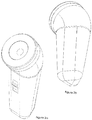
- An exemplary razor of the present invention comprises a foil assembly, a central retainer 4, a head 5, a blade assembly, a motor 9, a body 10, a switch 11 and a central mount 12.
- the foil assembly comprises a foil 1, an inner collar 2 and an outer collar 3.
- the blade assembly comprises a blade carrier 6, blade supports 7 and blades 8.
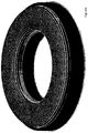
- the foil is substantially hemi-toroidal. That is it is the surface of half a circular cross-section toroidal form, that torus being divided in half by a plane perpendicular to the axis of revolution of the torus and passing through the center of revolution of the torus. It can also be described as the surface of a donut cut in half through its thickest part. It therefore has an inner and an outer edge, both circular in form, and a hole through the middle. It is curved in the circumferential direction to form a ring and it is curved in the radial direction between the inner and outer edge to form an arc in cross-section. It is therefore curved in two orthogonal planes.
- the shape is formed by a curve and a point on a plane, the point being at a distance from the curve.
- the surface of the foil is created by sweeping the curve 360 degrees around the point, the point being the center of rotation.
- the foil is spaced radially from the center of rotation.
- the surface of the foil 1 is provided with holes of a size and shape suitable for permitting hair follicles to pass through, such as is known in the art.
- the holes may be substantially circular, substantially triangular or any other suitable form.
- the hole shapes may be a mixture of circles, triangles, squares, pentagons, hexagons, heptagons, octagons or irregular shapes.
- the array of holes leaves a mesh of the material of the foil 1.
- the axes of the holes in the exemplary embodiment are parallel but may alternatively be perpendicular to the local surface of the foil 1 i'e' all pointing in different directions.
- the foil 1 may be made from metal, preferably a form of steel, but may be made from any other suitable material.
- the shape of the foil is suitable for engaging a large surface area of the user's face in order to perform efficient shaving.
- the three dimensional curvature of the foil is complementary to the three dimensional curvature of the face.
- the continuously varying curvature of the foil permits hair follicles to be engaged at a wide variety of directions and surface incidence angles permitting more effective shaving.
- Suitable methods of manufacture of the foil are known in the art but may include hot or cold pressing of flat annular blanks.
- the hole array may be pressed before, during or after the pressing of the flat blank.
- the inner 2 and outer 3 collars are bonded to the inner and outer edges of the foil 1.
- the inner collar 2 is circular and is provided with a circular groove 2a in its upper surface suitable for receiving the inner edge of the foil 1.
- the inner edge of the upper surface of the inner collar 2 is provided with a bevelled surface 2b for engaging with the outer edge 4b of the lower surface of the central retainer 4.
- the outer collar 3 is circular and is provided with a circular groove 3a in its upper surface for receiving the outer edge of the foil 1.
- the outer collar 3 engages with the upper rim of the head 5.
- the engagement is provided by threads on the lateral engagement surfaces, male thread on the head and female thread 3b on the outer collar.
- a press-button release means may be provided as is known in the art.
- the central retainer 4 is circular and has a concave upper surface 4a. This permits convexly curved features of the face, e'g' the chin, to pass into the center of the foil which permits enhanced engagement of hair follicles around the convexly curved feature during shaving.
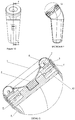
- the outer edge 4b of the underside of the central retainer 4 is shaped for complimentary engagement of the bevelled surface 2b of the inner collar 2, as can be seen in figure 10 . Therefore when assembled, the central retainer 4 retains the inner collar 2 and as the inner collar is bonded to the inner edge of the foil 1 in its groove 2a, the inner edge of the foil is retained to the razor.
- the central retainer has a threaded shaft 4c projecting downwards from its lower surface. The threaded shaft 4c engages with a complementary threaded hole 12a in the central mount 12 when assembled.
- the central mount 12 can be seen in figure 4 .
- the central mount is generally circular with a threaded hole 12a in the center of its upper surface.
- the upper surface 12b of the central mount 12 is recessed to receive and mount the disk motor 9.
- the lower housing 9b of the disk motor 9 is fixedly mounted to the central mount 12 by suitable means.
- the outer edge of the central mount is attached to the inner surface of the head 5 by suitable means.
- the central mount may be co-formed with the head 5 and therefore integral to it.
- the disk motor 9 is formed from upper and lower housings 9a and 9b respectively.
- the upper and lower housings are annular in form and are held apart and permitted to rotate relatively by bearings 9c.
- Permanent magnets are provided in the lower surface of the upper housing 9a.
- Corresponding electromagnets 9d are provided in the upper surface of the lower housing 9b. Interaction between the magnets causes rotation of the motor about the common axis of the upper and lower housings.
- the lower housing 9b is mounted upon and fixed to the central mount 12.
- the upper housing is provided with holes 9e in its upper surface which receive complementary lugs 6a in the lower surface of the blade carrier 6. As the lower housing 9b is fixed, relative rotation of the upper and lower housings causes rotation of the upper housing 9a with respect to the head 5.
- a more conventional motor may be used in the razor.
- Such a motor might drive a shaft with a toothed cog on its end.
- the toothed cog may engage with teeth formed on the inner edge or lower surface of the blade carrier thereby causing it to rotate when the motor is active.
- a biasing arrangement may be incorporated to press the blade carrier upwards to cause the blades 8 to engage with the lower surface of the foil 1.
- Two or more motors each driving a cog wheel or two or more cog wheels driven by one or more motors may be used to balance the upward force on the blade carrier 6.
- the blade carrier 6 is annular and is provided with lugs 6a on its lower surface.
- the lugs 6a may incorporate springs arranged to press against the bottom surface of the holes 9e to cause the blade assembly to be pushed upwards from the motor 9 and consequently for the blades 8 to be pressed against the lower surface of the foil 1.
- a single large diameter spring may be provided between the motor 9 and blade carrier 6 for this purpose.
- lugs 6a are provided in the exemplary embodiment but any suitable number, size and form may be used. Many other suitable means of providing releasable and biased engagement are known.
- Angularly spaced radiating grooves 6b are provided in the upper surface of the blade carrier 6. The grooves 6b radiate from the center of the annulus.
- the blade carrier 6 may be provided with cylindrical sides extending upward from the inner and outer edges of its upper surface. Such sides create an annular trough for collecting shavings. Such an arrangement makes cleaning easier and helps prevent shavings entering other areas of the razor. Suitable seals may be provided between moving and stationary parts to prevent problems related to ingress of shavings.
- Blade supports 7 are bonded into the grooves 6b such that they stand vertical to the plane of the blade carrier 6.
- the blade supports 7 have a shape suitable for engaging with the grooves 6b at their lower end and engaging with the blades 8 at their upper end. Consequently the blades 8 are arranged angularly spaced in a circular formation in an arrangement suitable for simultaneous engagement with the lower surface of the foil 1.
- Circular holes 7a are provided through the center of the blade supports 7 to reduce weight and permit air to flow through to reduce air resistance and therefore energy consumption.
- the blade carrier and blade supports may be integrally formed.
- the upper surface of the blades 8 are curved to complement the curvature of the lower surface of the foil 1 with which they are in contact.
- the upper surface therefore has the form of a segment of part of a toroidal surface, as the foil 1 itself is part-toroidal.
- the foil and blades are therefore complementary in form.
- the cutting edges have a positive rake angle.
- a positive rake angle means surfaces forming the cutting edge meet at an included angle of less than a right angle. This creates a sharper cutting edge than in conventional foil razors and results in a cleaner cut.
- each blade may have two cutting edges in order to be effective in either direction of rotation. This may be determined by what type of motor is used. The direction of rotation of some simpler motors may be determined by the relative position of the magnets at the instant the motor is activated.
- the blades 8 are pressed lightly against the lower surface of the foil 1 by the biasing arrangement between the blade carrier and the upper housing 9a, there will be slight wearing over time. As the cutting edges of the blades 8 have a positive rake angle, this wearing will keep the blades sharp.
- the relative hardness of the materials of the foil 1 and blades 8 may be chosen to maximize the advantage of this effect.
- the blade arrangement is purely exemplary and many alternative arrangements may be used.
- the blades 8 may attach directly to the blade carrier and may be arch-like in form such that they have a curved blade edge for engaging with the foil and two parallel legs to connect with the blade carrier. Consequently no blade support is required.
- Such a blade would have an airgap through it. Such an airgap would reduce air resistance to the movement of the blade assembly.
- the blade supports may be extensible in the vertical direction and spring loaded so instead of the biasing being between the motor and the blade carrier, the upward bias is between the blade carrier and the blades.
- the central retainer 4 is rotated by the user's thumbs to cause it to unscrew and disengage from the threaded hole 12a in the central mount 12.
- the foil assembly by the outer collar 3 is disengaged from the head by rotating it on its threads or released depending on the retention mechanism. The foil assembly comes away as a unit.
- the blade assembly can then be removed from the motor 9 as the lugs 6a are not retained in the holes 9e.
- upper and lower are intended to refer to the orientation generally expected for the razor when used i'e' when handheld, the foil 1 being uppermost and the body being lowermost.
- the foil may be defined as:
- a razor comprising such a foil may be defined as:
Landscapes
- Life Sciences & Earth Sciences (AREA)
- Forests & Forestry (AREA)
- Engineering & Computer Science (AREA)
- Mechanical Engineering (AREA)
- Dry Shavers And Clippers (AREA)
Applications Claiming Priority (1)
| Application Number | Priority Date | Filing Date | Title |
|---|---|---|---|
| IE20160175A IE86890B1 (en) | 2016-06-24 | 2016-06-24 | Foil for an electric razor and an electric razor comprising such a foil |
Publications (1)
| Publication Number | Publication Date |
|---|---|
| EP3260253A1 true EP3260253A1 (fr) | 2017-12-27 |
Family
ID=59152622
Family Applications (1)
| Application Number | Title | Priority Date | Filing Date |
|---|---|---|---|
| EP17075010.3A Withdrawn EP3260253A1 (fr) | 2016-06-24 | 2017-06-21 | Feuille pour un rasoir electrique et un rasoir electrique comprenant un tel film |
Country Status (2)
| Country | Link |
|---|---|
| EP (1) | EP3260253A1 (fr) |
| IE (1) | IE86890B1 (fr) |
Cited By (1)
| Publication number | Priority date | Publication date | Assignee | Title |
|---|---|---|---|---|
| EP4711102A1 (fr) * | 2024-09-05 | 2026-03-18 | Maxell Izumi Co., Ltd. | Rasoir électrique rotatif |
Citations (8)
| Publication number | Priority date | Publication date | Assignee | Title |
|---|---|---|---|---|
| US3019525A (en) * | 1960-06-29 | 1962-02-06 | Bruecker John | Shear plate and cutter assembly for rotary type dry shaver |
| US3119180A (en) * | 1961-12-20 | 1964-01-28 | Bruecker John | Shear plate and cutter assembly for rotary-type dry shaver |
| US3618210A (en) * | 1966-09-13 | 1971-11-09 | Philips Corp | Dry-shaving apparatus having a deformable curved shear plate |
| US3639979A (en) * | 1966-09-20 | 1972-02-08 | Philips Corp | Dry-shaving apparatus |
| FR2207443A5 (fr) * | 1972-11-17 | 1974-06-14 | Bissell Inc | |
| DE2309208A1 (de) * | 1973-02-22 | 1974-09-05 | Meyer Hans Otto | Trockenrasierer mit mindestens einer rotierenden schermesseranordnung |
| US6515256B1 (en) * | 2000-04-13 | 2003-02-04 | Vincent P. Battaglia | Process for laser machining continuous metal strip |
| US20030070304A1 (en) * | 2001-10-15 | 2003-04-17 | Zachary Curello | Cutting foil for rotary shavers and manufacturing methods for producing same |
-
2016
- 2016-06-24 IE IE20160175A patent/IE86890B1/en not_active IP Right Cessation
-
2017
- 2017-06-21 EP EP17075010.3A patent/EP3260253A1/fr not_active Withdrawn
Patent Citations (8)
| Publication number | Priority date | Publication date | Assignee | Title |
|---|---|---|---|---|
| US3019525A (en) * | 1960-06-29 | 1962-02-06 | Bruecker John | Shear plate and cutter assembly for rotary type dry shaver |
| US3119180A (en) * | 1961-12-20 | 1964-01-28 | Bruecker John | Shear plate and cutter assembly for rotary-type dry shaver |
| US3618210A (en) * | 1966-09-13 | 1971-11-09 | Philips Corp | Dry-shaving apparatus having a deformable curved shear plate |
| US3639979A (en) * | 1966-09-20 | 1972-02-08 | Philips Corp | Dry-shaving apparatus |
| FR2207443A5 (fr) * | 1972-11-17 | 1974-06-14 | Bissell Inc | |
| DE2309208A1 (de) * | 1973-02-22 | 1974-09-05 | Meyer Hans Otto | Trockenrasierer mit mindestens einer rotierenden schermesseranordnung |
| US6515256B1 (en) * | 2000-04-13 | 2003-02-04 | Vincent P. Battaglia | Process for laser machining continuous metal strip |
| US20030070304A1 (en) * | 2001-10-15 | 2003-04-17 | Zachary Curello | Cutting foil for rotary shavers and manufacturing methods for producing same |
Cited By (1)
| Publication number | Priority date | Publication date | Assignee | Title |
|---|---|---|---|---|
| EP4711102A1 (fr) * | 2024-09-05 | 2026-03-18 | Maxell Izumi Co., Ltd. | Rasoir électrique rotatif |
Also Published As
| Publication number | Publication date |
|---|---|
| IE86890B1 (en) | 2018-04-04 |
| IE20160175A1 (en) | 2017-12-27 |
Similar Documents
| Publication | Publication Date | Title |
|---|---|---|
| EP3173197B1 (fr) | Rasoir électrique rotatif et procédé de fabrication de lame interne de rasoir électrique rotatif | |
| US8827278B2 (en) | Adaptor for adapting a working element to an end of a power tool shaft | |
| CN202640308U (zh) | 一种能够附接到电动工具输出轴的配件 | |
| EP1787767B1 (fr) | Rasoir électrique rotatif | |
| US9440325B2 (en) | Adaptable abrasive cutting assembly for sharpener | |
| US10668634B2 (en) | Oscillating rotary shaver | |
| JP6005495B2 (ja) | ロータリー式電気かみそりの外刃の製造方法 | |
| JP5578724B2 (ja) | ロータリー式電気かみそり | |
| US4860450A (en) | Surface stripper | |
| JP2020039651A (ja) | 回転式シェーバー及びその内刃 | |
| US20110016722A1 (en) | Razor system | |
| EP3260253A1 (fr) | Feuille pour un rasoir electrique et un rasoir electrique comprenant un tel film | |
| US3417800A (en) | Grinding apparatus | |
| WO2012139508A1 (fr) | Outil motorisé et son ventilateur | |
| US9433323B2 (en) | Cutting implement for food processor | |
| EP2853330B1 (fr) | Lame de scie | |
| JP5649214B2 (ja) | ロータリー式電気かみそり | |
| KR101691924B1 (ko) | 회전드럼식 전기면도기의 절삭날 어셈블리 | |
| JP3196845U (ja) | 切削カッタ | |
| JP4346516B2 (ja) | 刃物研ぎ具 | |
| JPH0438666Y2 (fr) | ||
| JP2006014641A (ja) | 回転切断刃 | |
| RU157879U1 (ru) | Диск сферический прорезной | |
| WO2020039867A1 (fr) | Rasoir rotatif et lame interne de celui-ci | |
| KR101310756B1 (ko) | 그라인더의 회전날 조립체 |
Legal Events
| Date | Code | Title | Description |
|---|---|---|---|
| PUAI | Public reference made under article 153(3) epc to a published international application that has entered the european phase |
Free format text: ORIGINAL CODE: 0009012 |
|
| AK | Designated contracting states |
Kind code of ref document: A1 Designated state(s): AL AT BE BG CH CY CZ DE DK EE ES FI FR GB GR HR HU IE IS IT LI LT LU LV MC MK MT NL NO PL PT RO RS SE SI SK SM TR |
|
| AX | Request for extension of the european patent |
Extension state: BA ME |
|
| STAA | Information on the status of an ep patent application or granted ep patent |
Free format text: STATUS: THE APPLICATION IS DEEMED TO BE WITHDRAWN |
|
| 18D | Application deemed to be withdrawn |
Effective date: 20180628 |