EP3260260A1 - Dispositif de compactage pour le pressage d'articles céramiques - Google Patents
Dispositif de compactage pour le pressage d'articles céramiques Download PDFInfo
- Publication number
- EP3260260A1 EP3260260A1 EP17175631.5A EP17175631A EP3260260A1 EP 3260260 A1 EP3260260 A1 EP 3260260A1 EP 17175631 A EP17175631 A EP 17175631A EP 3260260 A1 EP3260260 A1 EP 3260260A1
- Authority
- EP
- European Patent Office
- Prior art keywords
- load
- leveler
- main direction
- conveyor belt
- pressing
- Prior art date
- Legal status (The legal status is an assumption and is not a legal conclusion. Google has not performed a legal analysis and makes no representation as to the accuracy of the status listed.)
- Granted
Links
Images



Classifications
-
- B—PERFORMING OPERATIONS; TRANSPORTING
- B28—WORKING CEMENT, CLAY, OR STONE
- B28B—SHAPING CLAY OR OTHER CERAMIC COMPOSITIONS; SHAPING SLAG; SHAPING MIXTURES CONTAINING CEMENTITIOUS MATERIAL, e.g. PLASTER
- B28B3/00—Producing shaped articles from the material by using presses; Presses specially adapted therefor
- B28B3/02—Producing shaped articles from the material by using presses; Presses specially adapted therefor wherein a ram exerts pressure on the material in a moulding space; Ram heads of special form
-
- B—PERFORMING OPERATIONS; TRANSPORTING
- B28—WORKING CEMENT, CLAY, OR STONE
- B28B—SHAPING CLAY OR OTHER CERAMIC COMPOSITIONS; SHAPING SLAG; SHAPING MIXTURES CONTAINING CEMENTITIOUS MATERIAL, e.g. PLASTER
- B28B3/00—Producing shaped articles from the material by using presses; Presses specially adapted therefor
- B28B3/02—Producing shaped articles from the material by using presses; Presses specially adapted therefor wherein a ram exerts pressure on the material in a moulding space; Ram heads of special form
- B28B3/024—Producing shaped articles from the material by using presses; Presses specially adapted therefor wherein a ram exerts pressure on the material in a moulding space; Ram heads of special form the pressure on the material being transmitted through flexible or resilient wall parts, e.g. flexible cushions on the ramming surface, resilient wall parts pressing as a result of deformation caused by ram pressure
-
- B—PERFORMING OPERATIONS; TRANSPORTING
- B28—WORKING CEMENT, CLAY, OR STONE
- B28B—SHAPING CLAY OR OTHER CERAMIC COMPOSITIONS; SHAPING SLAG; SHAPING MIXTURES CONTAINING CEMENTITIOUS MATERIAL, e.g. PLASTER
- B28B13/00—Feeding the unshaped material to moulds or apparatus for producing shaped articles; Discharging shaped articles from such moulds or apparatus
- B28B13/02—Feeding the unshaped material to moulds or apparatus for producing shaped articles
- B28B13/0215—Feeding the moulding material in measured quantities from a container or silo
-
- B—PERFORMING OPERATIONS; TRANSPORTING
- B28—WORKING CEMENT, CLAY, OR STONE
- B28B—SHAPING CLAY OR OTHER CERAMIC COMPOSITIONS; SHAPING SLAG; SHAPING MIXTURES CONTAINING CEMENTITIOUS MATERIAL, e.g. PLASTER
- B28B13/00—Feeding the unshaped material to moulds or apparatus for producing shaped articles; Discharging shaped articles from such moulds or apparatus
- B28B13/02—Feeding the unshaped material to moulds or apparatus for producing shaped articles
- B28B13/0295—Treating the surface of the fed layer, e.g. removing material or equalization of the surface
-
- B—PERFORMING OPERATIONS; TRANSPORTING
- B28—WORKING CEMENT, CLAY, OR STONE
- B28B—SHAPING CLAY OR OTHER CERAMIC COMPOSITIONS; SHAPING SLAG; SHAPING MIXTURES CONTAINING CEMENTITIOUS MATERIAL, e.g. PLASTER
- B28B5/00—Producing shaped articles from the material in moulds or on moulding surfaces, carried or formed by, in or on conveyors irrespective of the manner of shaping
- B28B5/02—Producing shaped articles from the material in moulds or on moulding surfaces, carried or formed by, in or on conveyors irrespective of the manner of shaping on conveyors of the endless-belt or chain type
- B28B5/021—Producing shaped articles from the material in moulds or on moulding surfaces, carried or formed by, in or on conveyors irrespective of the manner of shaping on conveyors of the endless-belt or chain type the shaped articles being of definite length
-
- B—PERFORMING OPERATIONS; TRANSPORTING
- B30—PRESSES
- B30B—PRESSES IN GENERAL
- B30B11/00—Presses specially adapted for forming shaped articles from material in particulate or plastic state, e.g. briquetting presses, tabletting presses
- B30B11/02—Presses specially adapted for forming shaped articles from material in particulate or plastic state, e.g. briquetting presses, tabletting presses using a ram exerting pressure on the material in a moulding space
-
- B—PERFORMING OPERATIONS; TRANSPORTING
- B30—PRESSES
- B30B—PRESSES IN GENERAL
- B30B11/00—Presses specially adapted for forming shaped articles from material in particulate or plastic state, e.g. briquetting presses, tabletting presses
- B30B11/02—Presses specially adapted for forming shaped articles from material in particulate or plastic state, e.g. briquetting presses, tabletting presses using a ram exerting pressure on the material in a moulding space
- B30B11/14—Presses specially adapted for forming shaped articles from material in particulate or plastic state, e.g. briquetting presses, tabletting presses using a ram exerting pressure on the material in a moulding space co-operating with moulds on a movable carrier other than a turntable or a rotating drum
-
- B—PERFORMING OPERATIONS; TRANSPORTING
- B30—PRESSES
- B30B—PRESSES IN GENERAL
- B30B15/00—Details of, or accessories for, presses; Auxiliary measures in connection with pressing
- B30B15/30—Feeding material to presses
- B30B15/302—Feeding material in particulate or plastic state to moulding presses
Definitions
- the object of the present invention is a compacting device for pressing ceramic articles, in particular plates, tiles and the like.
- the invention also refers to a pressing device for ceramic articles.
- the invention is particularly advantageous in a device for pressing ceramic articles, ideated by the applicant itself and known in the field from the publication EP1500480 , in which the powder material to be pressed is arranged in layer form on an abutment plane constituted by the upper face of a conveyor belt, which is slidably supported on a pressing member or lower pad.
- the pressing is executed with a pressing member or upper pad through the interposition of a closed-loop belt, whose external surface is directed towards the conveyor belt.
- the upper pad is provided with a frame, fixed or replaceable, that projects downward.
- a forming frame also has the task of generating in the load, following the pressing, an edge characterized by a compaction or material density greater than that of the internal zones, wherein by greater material density it is intended a reduction of the overall space occupied by the material.
- the presence of denser and more compact lateral zones considerably simplifies the removal and trimming of the loads after pressing. This occurs since the denser zones can perfectly withstand, without crumbling, the removal of the incoherent material that is situated along the external edges of the pressed load, allowing the obtainment of precise, clear edges of the load.
- the currently available device while being effective and functional, can be improved regarding flexibility with respect to the change of size of the articles to be pressed. Indeed, in the currently available device, changing the size of the ceramic article requires changing the projecting frame with a frame shaped for executing the pressing of the new size. This represents a drawback both regarding processing times, since the substitution of the frame requires stopping the pressing line, and regarding costs, since it requires the availability of a certain number of different-size frames.
- the object of the present invention is to offer a compacting device that allows overcoming the abovementioned drawbacks.
- One advantage of the compacting device according to the present invention is to allow a change of size in considerably lower times with respect to those of the currently available devices.
- the compacting device according to the present invention is particularly but not exclusively recommended for being used in a pressing device provided with a conveyor belt (T) that is movable along a main direction (X), for the forward movement of a load (S) of incoherent ceramic material to be pressed.
- a press (P) is arranged along the conveyor belt (T) in a manner so as to receive the load (S) carried forward by the conveyor belt (T). Both the belt (T) and the load (S) arranged on the belt (T) move between the two pads of the press (P), such that the load (S) is pressed directly on the belt (T).
- width will indicate a size measured on a horizontal plane perpendicular to the main direction (X), while “height” or “thickness” will indicate a size measured along a vertical direction.
- the compacting device comprises a first leveler (2), which is structured to come into contact with two lateral zones of the load (S) and to push such lateral zones towards one another, perpendicular to the main direction (X).
- the first leveler (2) in other words, compacts the load (S) perpendicular to the main direction (X), pushing the two lateral zones thereof, which are overall parallel to the main direction (X), towards one another.
- the incoherent material of the lateral zones of the load is collected, forming two stacks (As), substantially parallel to the main direction (X), whose maximum level exceeds the level of the remaining zones of the load (S) itself.
- the first leveler (2) comprises a pair of side walls (21,22) movable towards and away from one another along a horizontal direction, perpendicular to the main direction (X).
- the intervention of the side walls (21,22) is actuated during a rest phase of the load (S), i.e. during a stop of the conveyor belt (T).
- a load (S) is carried into and stopped in an intermediate position with respect to the side walls (21,22). Starting from a position of maximum mutual distance, in which they do not interfere with the load (S), the side walls (21,22) are moved closer together by means of actuators that are not illustrated in detail, for example pneumatic or hydraulic cylinders.
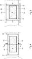
- the side walls (21,22) By moving closer together up to a minimum distance position ( figure 4 ), the side walls (21,22) come into contact with the lateral zones of the load (S), creating the previously-described stacks of greater height. Once the step of compaction of the lateral zones of the load (S) has terminated, the side walls (21,22) return to the maximum distance position, such that the load (S) can once again be moved forward and a new load (S) can be carried to the side walls (21,22).
- the actuators which drive the side walls (21,22) can advantageously be remotely controlled by means of a control module, for example in order to adapt the travel of the side walls (21,22) to different-size loads (S).
- the side walls (21,22) have a front surface, intended to come into contact with the load (S), which is arranged in a substantially vertical position.
- the side walls (21,22) can have the form of laminas or strips, arranged with the greater surface thereof vertical.
- the front surface of the side walls (21,22) could also assume a different shape, e.g. convex or tilted.
- the first leveler (2) comprises a pair of side walls (21,22) arranged to converge with each other in a forward direction of the load (S).
- the lateral zones of the load (S) come into contact with the side walls (21,22), and are compacted, during the transport of the load (S).
- the side walls (21,22) remain fixed during the forward movement of the load (S).
- Each side wall (21,22) comprises a front surface, directed towards the belt (T) and towards the other side wall, situated above the belt (T), at a height such to be able to come into contact with the load (S).
- the height of the side walls (21,22) can be adjustable with respect to the conveyor belt (T), in order to adapt the position of the side walls (21) to the thickness or height of the load (S).
- the position of the side walls (21,22) can be adjustable along a horizontal direction perpendicular to the main direction (X), in order to allow adapting the position of the side walls (21,22) to the width of the load (S), as well as adjusting the level of compaction on the lateral zones of the load (S), and hence adjusting the height of the stacks that are formed in the lateral zones of the load (S).
- motorized or manual regulators In order to adjust the position of the side walls (21,22), it is possible to arrange motorized or manual regulators, as is within the capacity of the man skilled in the art.
- the use of motorized regulators allows modifying the position of the side walls (21,22) by means of remote controls, for example for an adaptation to loads (S) of different size.
- the side walls (21,22) are in the form of laminas or strips, arranged with the greater surface thereof in substantially vertical position.
- the compacting device can also be provided with a second leveler (3), which is structured to come into contact with a front zone and with a rear zone of the load (S) and to push such zones towards one another, parallel to the main direction (X).
- the second leveler performs, on the front zone and on the rear zone of the load (S), the same action that the first leveler (2) performs on the lateral zones of the load (S).
- the incoherent material of the front and rear zones of the load is collected, forming two stacks (Af,Ar), substantially perpendicular to the main direction (X), whose maximum level exceeds the level of the remaining zones of the load (S) itself.
- the load (S) then has a substantially rectangular perimeter zone, comprising a stack (As,Af,Ar) of incoherent material whose maximum level exceeds the level of the remaining zones of the load (S) itself.
- a stack As,Af,Ar
- the load (S) comprises a closed perimeter zone, which follows the entire border of the load (S) itself, in which the incoherent material has greater compaction and material density. This allows facilitating and making more precise the trimming operations of the entire border of the load (S).
- the second leveler (3) is movable along a vertical direction between a lower position ( figure 1 ), in which it is able to come into contact with a load (S), and an upper position ( figure 2 ), in which it does not interfere with the load (S).
- the second leveler (3) In the upper position ( figure 2 ), the second leveler (3) allows the transit of the load (S) on the conveyor surface (T).
- Actuators of known type, not illustrated in detail, are arranged for allowing the vertical movement of the second leveler (3).
- the second leveler (3) comprises a pair of side walls (31,32) movable towards and away from one another, parallel to the main direction (X).
- the side walls (31,32) have a front surface, intended to come into contact with the load (S), which is arranged in a substantially vertical position.
- the side walls (31,32) can have the form of laminas or strips, arranged with the greater surface thereof vertical.
- Actuators that are within the capacity of the man skilled in the art can be used for driving the side walls (31,32). Such actuators can advantageously be remotely controlled by means of a control module, for example for adapting the travel of the side walls (31,32) to different-size loads (S).
- the intervention of the side walls (31,32) is actuated during a rest phase of the load (S), or during a stop of the conveyor belt (T).
- a load (S) can be carried into and stopped in a zone comprised between the side walls (31,32).
- the second leveler (3) is moved into its lower position ( figure 2 ), in which the side walls (31,32) can come into contact with the load (S).
- the side walls (31,32) are moved closer together by means of actuators not illustrated in detail, e.g. pneumatic or hydraulic cylinders.
- the side walls (31,32) By moving closer to each other up to a position of minimum distance ( figure 5 ), the side walls (31,32) come into contact with the front and rear zones of the load (S), creating the previously-described stacks of greater height. Once the step of compaction of the front and rear zones of the load (S) has terminated, the side walls (31,32) return to the position of maximum distance and they are lifted towards the upper position, such that the load (S) can once again be moved forward and a new load (S) can be carried to the side walls (31,32).
- the first leveler (2) is movable along a vertical direction between a lower position ( figure 2 ), in which it is able to come into contact with a load (S), and an upper position ( figure 1 ), in which it does not interfere with the load (S).
- the first leveler (2) in the embodiment comprising the side walls (21,22), can be associated with the second leveler (3) in order to form a group that is integral with respect to the vertical translation.
- the intervention of the two levelers (2,3) is actuated during a stop of the conveyor belt (T).
- the two levelers which are initially found in upper position, are lowered into lower position. In such position, each successively executes its own compaction travel. Once the compaction travels have terminated, the two levelers (2,3) are brought back into upper position and the conveyor belt (T) once again moves forward towards the press (P).
- the first leveler (2) could also not be integral with the second leveler (3) with respect to the vertical translation. This occurs since the second leveler (2) does not obstruct the forward movement of the load (S) when the side walls (21,22) are situated in widened position. The second leveler (2), during the operation of the pressing device, could therefore always remain in lower position, and be lifted for example for the execution of maintenance operations.
- the compactor according to the present invention is particularly effective in a pressing device in which the conveyor belt (T) assumes a continuous configuration, or in a configuration in which it comprises a first portion (T1) and a second portion (T2), consecutive with respect to each other, which are movable independently of one another.
- a feeding device (F) is arranged along an initial portion of the conveyor belt (T). If the conveyor belt (T) comprises the two portions (T1,T2), the feeding device (F) is arranged along the first portion (T1) in order to deposit a load (S) on the first portion (T1) itself.
- the feeding device (F) is, for example, in the form of a hopper provided with a lower discharge opening.
- the feeding device (F) operates on the first portion (T1), i.e. the loads (S) are deposited on the first portion (T1).
- the front end of the first portion (T1) is at least partially above a rear end of the second portion (T2), at a height slightly greater than the second portion (T2).
- first and a second portion (T1,T2), independent of one another, allows managing the intervention of the compacting device with considerable flexibility.
- the first portion (T1) can be driven to move forward in order to allow the deposition of a load (S).
- the step of depositing a load (S) can be synchronized with the intervention of the compacting device, so as to terminate before or simultaneously with the intervention of the compacting device.
- the first and the second portion can be driven forward in order to execute the transfer of the load (S) deposited on the first portion, and to simultaneously transfer the load (S) that has undergone compaction towards the press (P).
- the conveyor belt (T) comprises the first and the second portion (T1,T2) that are movable independently of one another, it is possible to form the stacks (Af,Ar) in the front and rear zones of the load by modifying the forward movement velocity of the two portions, in a manner such that, during the transfer of the front zone and of the rear zone of the load (S) from the first portion to the second portion, a reduction of the forward movement velocity of the load is produced. This causes the formation of the stacks (Af,Ar).
- the front zone of the load (S) transits from the first portion (T1) to the second portion (T2)
- the compacting device allows obtaining important advantages.
- the compacting device allows attaining loads (S) with a perimeter zone of greater material density, without arranging pressing pads provided with projecting edges or frames. This allows reducing the cost of the pressing pads and simultaneously reducing the adaptation times with a change of size of the loads (S) to be pressed. Indeed, it is sufficient to modify the travel and/or the mutual distance of the side walls (21,22,31,32) in order to be able to attain the stacks (As,Af,Ar) in loads (S) of different size.
- the changes of size of the loads (S) can be managed without having to stop the pressing line so to execute adaptation interventions; rather, it will suffice to simply adjust the travel or the mutual distance between the side walls (21,22,31,32).
- Such adjustment can occur through remote controls on the actuators set for driving the side walls themselves, or on suitable regulators that can be arranged for the levelers (2,3).
Landscapes
- Engineering & Computer Science (AREA)
- Mechanical Engineering (AREA)
- Manufacturing & Machinery (AREA)
- Chemical & Material Sciences (AREA)
- Ceramic Engineering (AREA)
- Press Drives And Press Lines (AREA)
- Delivering By Means Of Belts And Rollers (AREA)
- Devices For Post-Treatments, Processing, Supply, Discharge, And Other Processes (AREA)
- Press-Shaping Or Shaping Using Conveyers (AREA)
- Structure Of Belt Conveyors (AREA)
Applications Claiming Priority (1)
| Application Number | Priority Date | Filing Date | Title |
|---|---|---|---|
| ITUA2016A004452A ITUA20164452A1 (it) | 2016-06-16 | 2016-06-16 | Dispositivo compattatore per la pressatura di manufatti ceramici |
Publications (2)
| Publication Number | Publication Date |
|---|---|
| EP3260260A1 true EP3260260A1 (fr) | 2017-12-27 |
| EP3260260B1 EP3260260B1 (fr) | 2021-08-04 |
Family
ID=57750354
Family Applications (1)
| Application Number | Title | Priority Date | Filing Date |
|---|---|---|---|
| EP17175631.5A Active EP3260260B1 (fr) | 2016-06-16 | 2017-06-13 | Procédé de compactage pour le pressage d'articles céramiques |
Country Status (4)
| Country | Link |
|---|---|
| EP (1) | EP3260260B1 (fr) |
| CN (1) | CN107520945B (fr) |
| ES (1) | ES2893104T3 (fr) |
| IT (1) | ITUA20164452A1 (fr) |
Cited By (4)
| Publication number | Priority date | Publication date | Assignee | Title |
|---|---|---|---|---|
| CN112810336A (zh) * | 2021-01-25 | 2021-05-18 | 徐的莲 | 一种文具生产用印泥成型设备 |
| IT202000016273A1 (it) * | 2020-07-06 | 2022-01-06 | Siti B & T Group Spa | Attrezzatura per la realizzazione di lastre in materiale ceramico |
| CN117042942A (zh) * | 2021-03-29 | 2023-11-10 | 系统陶瓷股份公司 | 用于压实陶瓷材料的装置和方法 |
| IT202400004453A1 (it) * | 2024-02-29 | 2025-08-29 | Sacmi Cooperativa Mecc Imola Societa’ Cooperativa | Metodo e sistema di compattazione per la compattazione di materiale in polvere ceramica |
Families Citing this family (2)
| Publication number | Priority date | Publication date | Assignee | Title |
|---|---|---|---|---|
| IT201800005064A1 (it) * | 2018-05-04 | 2019-11-04 | Dispositivo di livellamento per materiali in polvere o granuli | |
| CN114592690B (zh) * | 2022-04-07 | 2024-05-07 | 深圳大学 | 一种压缩浇筑钢筋混凝土梁、柱的施工装置及施工方法 |
Citations (6)
| Publication number | Priority date | Publication date | Assignee | Title |
|---|---|---|---|---|
| US20010017428A1 (en) * | 1998-12-16 | 2001-08-30 | Stanislav Klasterka | Apparatus and a method for scattering particles to form a mat |
| CN1451524A (zh) * | 2002-12-16 | 2003-10-29 | 徐建 | 大规格陶瓷薄板的成型设备及其方法 |
| EP1500480A2 (fr) | 2003-07-22 | 2005-01-26 | System S.p.A. | Dispositif pour la fabrication d'articles en céramique comme par exemple des dalles, des carreaux et des articles similaires par pressage de poudre |
| WO2006095249A2 (fr) * | 2005-03-09 | 2006-09-14 | Mira Di Algeri Maris | Déplacement de matière granulée |
| US20140096887A1 (en) * | 2011-05-28 | 2014-04-10 | Dieffenbacher GmbH Maschinen-und Anlagenbau | Method and plant for producing material boards, and a device for compressing the narrow sides of a pressed-material mat |
| CN105563630A (zh) * | 2014-10-15 | 2016-05-11 | 钟细环 | 一种陶瓷砖的布料机构 |
Family Cites Families (8)
| Publication number | Priority date | Publication date | Assignee | Title |
|---|---|---|---|---|
| CH387293A (de) * | 1961-07-20 | 1965-01-31 | Interwood Ag | Verfahren und Anlage zur kontinuierlichen Herstellung von plattenförmigen Körpern aus Fasermaterial, insbesondere zur Herstellung von Holzspanplatten |
| FR1474341A (fr) * | 1966-03-25 | 1967-03-24 | Becker & Van Huellen | Presse pouvant être chauffée, fonctionnant par cycles, pour panneaux en copeaux agglomérés ou panneaux similaires |
| DE69428431T2 (de) * | 1993-11-04 | 2002-06-20 | Nikkiso Co., Ltd. | Verfahren und vorrichtung zum druckformen |
| IT1294941B1 (it) * | 1997-08-01 | 1999-04-23 | Ariostea S P A | Sistema di caricamento degli stampi delle presse per la formatura di piastrelle e relativi mezzi di attuazione. |
| ITRE20010127A1 (it) * | 2001-12-21 | 2003-06-21 | Sacmi | Metodo ed impianto per la fabbricazione di piastrelle e lastre ceramiche, e piastrelle e lastre ottenute con detti |
| ITMO20020175A1 (it) * | 2002-06-20 | 2003-12-22 | Ronflette Sa | Dispositivo per il carico di polveri |
| ITRE20040150A1 (it) * | 2004-12-10 | 2005-03-10 | Sacmi | Impianto perfezionato per la formatura di lastre o piastrelle ceramiche |
| ITRE20040152A1 (it) * | 2004-12-22 | 2005-03-22 | Sacmi | Sistema di compattazione a nastro di polveri ceramiche per la formatura di lastre |
-
2016
- 2016-06-16 IT ITUA2016A004452A patent/ITUA20164452A1/it unknown
-
2017
- 2017-06-13 ES ES17175631T patent/ES2893104T3/es active Active
- 2017-06-13 EP EP17175631.5A patent/EP3260260B1/fr active Active
- 2017-06-16 CN CN201710454213.5A patent/CN107520945B/zh active Active
Patent Citations (6)
| Publication number | Priority date | Publication date | Assignee | Title |
|---|---|---|---|---|
| US20010017428A1 (en) * | 1998-12-16 | 2001-08-30 | Stanislav Klasterka | Apparatus and a method for scattering particles to form a mat |
| CN1451524A (zh) * | 2002-12-16 | 2003-10-29 | 徐建 | 大规格陶瓷薄板的成型设备及其方法 |
| EP1500480A2 (fr) | 2003-07-22 | 2005-01-26 | System S.p.A. | Dispositif pour la fabrication d'articles en céramique comme par exemple des dalles, des carreaux et des articles similaires par pressage de poudre |
| WO2006095249A2 (fr) * | 2005-03-09 | 2006-09-14 | Mira Di Algeri Maris | Déplacement de matière granulée |
| US20140096887A1 (en) * | 2011-05-28 | 2014-04-10 | Dieffenbacher GmbH Maschinen-und Anlagenbau | Method and plant for producing material boards, and a device for compressing the narrow sides of a pressed-material mat |
| CN105563630A (zh) * | 2014-10-15 | 2016-05-11 | 钟细环 | 一种陶瓷砖的布料机构 |
Cited By (5)
| Publication number | Priority date | Publication date | Assignee | Title |
|---|---|---|---|---|
| IT202000016273A1 (it) * | 2020-07-06 | 2022-01-06 | Siti B & T Group Spa | Attrezzatura per la realizzazione di lastre in materiale ceramico |
| CN112810336A (zh) * | 2021-01-25 | 2021-05-18 | 徐的莲 | 一种文具生产用印泥成型设备 |
| CN117042942A (zh) * | 2021-03-29 | 2023-11-10 | 系统陶瓷股份公司 | 用于压实陶瓷材料的装置和方法 |
| IT202400004453A1 (it) * | 2024-02-29 | 2025-08-29 | Sacmi Cooperativa Mecc Imola Societa’ Cooperativa | Metodo e sistema di compattazione per la compattazione di materiale in polvere ceramica |
| WO2025181713A1 (fr) * | 2024-02-29 | 2025-09-04 | Sacmi Cooperativa Meccanici Imola Societa' Cooperativa | Procédé et système de compactage pour le compactage de matériau céramique en poudre |
Also Published As
| Publication number | Publication date |
|---|---|
| ITUA20164452A1 (it) | 2017-12-16 |
| EP3260260B1 (fr) | 2021-08-04 |
| CN107520945B (zh) | 2021-07-20 |
| CN107520945A (zh) | 2017-12-29 |
| ES2893104T3 (es) | 2022-02-08 |
Similar Documents
| Publication | Publication Date | Title |
|---|---|---|
| EP3260260B1 (fr) | Procédé de compactage pour le pressage d'articles céramiques | |
| RU2586929C1 (ru) | Система и способ уплотнения | |
| RU2606142C2 (ru) | Устройство и способ для прессования порошкового материала | |
| ITMO960151A1 (it) | Metodo e mezzi per la pressatura di pistrelle ceramiche | |
| CN103043429B (zh) | 一种钢筋强制分料机构、分料装置及分料方法 | |
| US2831213A (en) | Feeding moist mass cakes to presses | |
| US5567113A (en) | Apparatus and method for palletizing work pieces | |
| CA2625939C (fr) | Installation pour la fabrication de dalles de conglomerat de materiau pierreux | |
| EP3423268B1 (fr) | Dispositif de pressage | |
| CN101214697B (zh) | 裂纹砖布料装置 | |
| CN209425695U (zh) | 一种免托板静压砌块成型机 | |
| EP1500480B1 (fr) | Dispositif pour la fabrication d'articles en céramique comme par exemple des dalles, des carreaux et des articles similaires par pressage de poudre | |
| CN201579861U (zh) | 瓷质板材砖的成型装置 | |
| CN106976153B (zh) | 一种双层布料制砖压力机 | |
| EP0384745B1 (fr) | Dispositif de fabrication de blocs composites | |
| CN107263674A (zh) | 一种乐高砖成型机 | |
| CN108214827B (zh) | 一种双层制块压力机 | |
| EP1136211B1 (fr) | Dispositif pour la fabrication d'articles en céramique comme par exemple des dalles, des carreaux et des articles similaires par pressage de poudre | |
| NL194117C (nl) | Inrichting voor het vervaardigen van muurelementen. | |
| CN106738193B (zh) | 一种混凝土模卡砌块制造机 | |
| EP1358983B1 (fr) | Dispositif pour le remplissage des moules d'une presse pour la fabrication des carreaux | |
| CN110202679A (zh) | 一种移动式布料压坯装置及其布料方法 | |
| CN207954206U (zh) | 一种双层制块压力机 | |
| JPS61246008A (ja) | 平形成形品を製造する方法と装置 | |
| EP0519373A1 (fr) | Dispositif pour le chargement du matériau en poudre dans les moules des presses pour matière céramique |
Legal Events
| Date | Code | Title | Description |
|---|---|---|---|
| PUAI | Public reference made under article 153(3) epc to a published international application that has entered the european phase |
Free format text: ORIGINAL CODE: 0009012 |
|
| STAA | Information on the status of an ep patent application or granted ep patent |
Free format text: STATUS: THE APPLICATION HAS BEEN PUBLISHED |
|
| AK | Designated contracting states |
Kind code of ref document: A1 Designated state(s): AL AT BE BG CH CY CZ DE DK EE ES FI FR GB GR HR HU IE IS IT LI LT LU LV MC MK MT NL NO PL PT RO RS SE SI SK SM TR |
|
| AX | Request for extension of the european patent |
Extension state: BA ME |
|
| STAA | Information on the status of an ep patent application or granted ep patent |
Free format text: STATUS: REQUEST FOR EXAMINATION WAS MADE |
|
| 17P | Request for examination filed |
Effective date: 20180410 |
|
| RBV | Designated contracting states (corrected) |
Designated state(s): AL AT BE BG CH CY CZ DE DK EE ES FI FR GB GR HR HU IE IS IT LI LT LU LV MC MK MT NL NO PL PT RO RS SE SI SK SM TR |
|
| STAA | Information on the status of an ep patent application or granted ep patent |
Free format text: STATUS: EXAMINATION IS IN PROGRESS |
|
| 17Q | First examination report despatched |
Effective date: 20190416 |
|
| RAP1 | Party data changed (applicant data changed or rights of an application transferred) |
Owner name: SYSTEM CERAMICS S.P.A. |
|
| RIC1 | Information provided on ipc code assigned before grant |
Ipc: B30B 15/30 20060101ALI20201209BHEP Ipc: B28B 13/02 20060101ALI20201209BHEP Ipc: B28B 5/02 20060101ALI20201209BHEP Ipc: B28B 3/02 20060101AFI20201209BHEP Ipc: B30B 11/14 20060101ALI20201209BHEP Ipc: B30B 11/02 20060101ALI20201209BHEP |
|
| GRAP | Despatch of communication of intention to grant a patent |
Free format text: ORIGINAL CODE: EPIDOSNIGR1 |
|
| STAA | Information on the status of an ep patent application or granted ep patent |
Free format text: STATUS: GRANT OF PATENT IS INTENDED |
|
| INTG | Intention to grant announced |
Effective date: 20210301 |
|
| GRAS | Grant fee paid |
Free format text: ORIGINAL CODE: EPIDOSNIGR3 |
|
| GRAA | (expected) grant |
Free format text: ORIGINAL CODE: 0009210 |
|
| STAA | Information on the status of an ep patent application or granted ep patent |
Free format text: STATUS: THE PATENT HAS BEEN GRANTED |
|
| AK | Designated contracting states |
Kind code of ref document: B1 Designated state(s): AL AT BE BG CH CY CZ DE DK EE ES FI FR GB GR HR HU IE IS IT LI LT LU LV MC MK MT NL NO PL PT RO RS SE SI SK SM TR |
|
| REG | Reference to a national code |
Ref country code: GB Ref legal event code: FG4D |
|
| REG | Reference to a national code |
Ref country code: AT Ref legal event code: REF Ref document number: 1416508 Country of ref document: AT Kind code of ref document: T Effective date: 20210815 |
|
| REG | Reference to a national code |
Ref country code: CH Ref legal event code: EP |
|
| REG | Reference to a national code |
Ref country code: DE Ref legal event code: R096 Ref document number: 602017043222 Country of ref document: DE |
|
| REG | Reference to a national code |
Ref country code: IE Ref legal event code: FG4D |
|
| REG | Reference to a national code |
Ref country code: LT Ref legal event code: MG9D |
|
| REG | Reference to a national code |
Ref country code: NL Ref legal event code: MP Effective date: 20210804 |
|
| REG | Reference to a national code |
Ref country code: AT Ref legal event code: MK05 Ref document number: 1416508 Country of ref document: AT Kind code of ref document: T Effective date: 20210804 |
|
| PG25 | Lapsed in a contracting state [announced via postgrant information from national office to epo] |
Ref country code: RS Free format text: LAPSE BECAUSE OF FAILURE TO SUBMIT A TRANSLATION OF THE DESCRIPTION OR TO PAY THE FEE WITHIN THE PRESCRIBED TIME-LIMIT Effective date: 20210804 Ref country code: SE Free format text: LAPSE BECAUSE OF FAILURE TO SUBMIT A TRANSLATION OF THE DESCRIPTION OR TO PAY THE FEE WITHIN THE PRESCRIBED TIME-LIMIT Effective date: 20210804 Ref country code: PT Free format text: LAPSE BECAUSE OF FAILURE TO SUBMIT A TRANSLATION OF THE DESCRIPTION OR TO PAY THE FEE WITHIN THE PRESCRIBED TIME-LIMIT Effective date: 20211206 Ref country code: NO Free format text: LAPSE BECAUSE OF FAILURE TO SUBMIT A TRANSLATION OF THE DESCRIPTION OR TO PAY THE FEE WITHIN THE PRESCRIBED TIME-LIMIT Effective date: 20211104 Ref country code: HR Free format text: LAPSE BECAUSE OF FAILURE TO SUBMIT A TRANSLATION OF THE DESCRIPTION OR TO PAY THE FEE WITHIN THE PRESCRIBED TIME-LIMIT Effective date: 20210804 Ref country code: FI Free format text: LAPSE BECAUSE OF FAILURE TO SUBMIT A TRANSLATION OF THE DESCRIPTION OR TO PAY THE FEE WITHIN THE PRESCRIBED TIME-LIMIT Effective date: 20210804 Ref country code: AT Free format text: LAPSE BECAUSE OF FAILURE TO SUBMIT A TRANSLATION OF THE DESCRIPTION OR TO PAY THE FEE WITHIN THE PRESCRIBED TIME-LIMIT Effective date: 20210804 Ref country code: BG Free format text: LAPSE BECAUSE OF FAILURE TO SUBMIT A TRANSLATION OF THE DESCRIPTION OR TO PAY THE FEE WITHIN THE PRESCRIBED TIME-LIMIT Effective date: 20211104 Ref country code: LT Free format text: LAPSE BECAUSE OF FAILURE TO SUBMIT A TRANSLATION OF THE DESCRIPTION OR TO PAY THE FEE WITHIN THE PRESCRIBED TIME-LIMIT Effective date: 20210804 |
|
| REG | Reference to a national code |
Ref country code: ES Ref legal event code: FG2A Ref document number: 2893104 Country of ref document: ES Kind code of ref document: T3 Effective date: 20220208 |
|
| PG25 | Lapsed in a contracting state [announced via postgrant information from national office to epo] |
Ref country code: PL Free format text: LAPSE BECAUSE OF FAILURE TO SUBMIT A TRANSLATION OF THE DESCRIPTION OR TO PAY THE FEE WITHIN THE PRESCRIBED TIME-LIMIT Effective date: 20210804 Ref country code: LV Free format text: LAPSE BECAUSE OF FAILURE TO SUBMIT A TRANSLATION OF THE DESCRIPTION OR TO PAY THE FEE WITHIN THE PRESCRIBED TIME-LIMIT Effective date: 20210804 Ref country code: GR Free format text: LAPSE BECAUSE OF FAILURE TO SUBMIT A TRANSLATION OF THE DESCRIPTION OR TO PAY THE FEE WITHIN THE PRESCRIBED TIME-LIMIT Effective date: 20211105 |
|
| PG25 | Lapsed in a contracting state [announced via postgrant information from national office to epo] |
Ref country code: NL Free format text: LAPSE BECAUSE OF FAILURE TO SUBMIT A TRANSLATION OF THE DESCRIPTION OR TO PAY THE FEE WITHIN THE PRESCRIBED TIME-LIMIT Effective date: 20210804 |
|
| PG25 | Lapsed in a contracting state [announced via postgrant information from national office to epo] |
Ref country code: DK Free format text: LAPSE BECAUSE OF FAILURE TO SUBMIT A TRANSLATION OF THE DESCRIPTION OR TO PAY THE FEE WITHIN THE PRESCRIBED TIME-LIMIT Effective date: 20210804 |
|
| REG | Reference to a national code |
Ref country code: DE Ref legal event code: R097 Ref document number: 602017043222 Country of ref document: DE |
|
| PG25 | Lapsed in a contracting state [announced via postgrant information from national office to epo] |
Ref country code: SM Free format text: LAPSE BECAUSE OF FAILURE TO SUBMIT A TRANSLATION OF THE DESCRIPTION OR TO PAY THE FEE WITHIN THE PRESCRIBED TIME-LIMIT Effective date: 20210804 Ref country code: SK Free format text: LAPSE BECAUSE OF FAILURE TO SUBMIT A TRANSLATION OF THE DESCRIPTION OR TO PAY THE FEE WITHIN THE PRESCRIBED TIME-LIMIT Effective date: 20210804 Ref country code: RO Free format text: LAPSE BECAUSE OF FAILURE TO SUBMIT A TRANSLATION OF THE DESCRIPTION OR TO PAY THE FEE WITHIN THE PRESCRIBED TIME-LIMIT Effective date: 20210804 Ref country code: EE Free format text: LAPSE BECAUSE OF FAILURE TO SUBMIT A TRANSLATION OF THE DESCRIPTION OR TO PAY THE FEE WITHIN THE PRESCRIBED TIME-LIMIT Effective date: 20210804 Ref country code: CZ Free format text: LAPSE BECAUSE OF FAILURE TO SUBMIT A TRANSLATION OF THE DESCRIPTION OR TO PAY THE FEE WITHIN THE PRESCRIBED TIME-LIMIT Effective date: 20210804 Ref country code: AL Free format text: LAPSE BECAUSE OF FAILURE TO SUBMIT A TRANSLATION OF THE DESCRIPTION OR TO PAY THE FEE WITHIN THE PRESCRIBED TIME-LIMIT Effective date: 20210804 |
|
| PLBE | No opposition filed within time limit |
Free format text: ORIGINAL CODE: 0009261 |
|
| STAA | Information on the status of an ep patent application or granted ep patent |
Free format text: STATUS: NO OPPOSITION FILED WITHIN TIME LIMIT |
|
| 26N | No opposition filed |
Effective date: 20220506 |
|
| PG25 | Lapsed in a contracting state [announced via postgrant information from national office to epo] |
Ref country code: SI Free format text: LAPSE BECAUSE OF FAILURE TO SUBMIT A TRANSLATION OF THE DESCRIPTION OR TO PAY THE FEE WITHIN THE PRESCRIBED TIME-LIMIT Effective date: 20210804 |
|
| REG | Reference to a national code |
Ref country code: DE Ref legal event code: R119 Ref document number: 602017043222 Country of ref document: DE |
|
| PG25 | Lapsed in a contracting state [announced via postgrant information from national office to epo] |
Ref country code: MC Free format text: LAPSE BECAUSE OF FAILURE TO SUBMIT A TRANSLATION OF THE DESCRIPTION OR TO PAY THE FEE WITHIN THE PRESCRIBED TIME-LIMIT Effective date: 20210804 |
|
| REG | Reference to a national code |
Ref country code: CH Ref legal event code: PL |
|
| REG | Reference to a national code |
Ref country code: BE Ref legal event code: MM Effective date: 20220630 |
|
| GBPC | Gb: european patent ceased through non-payment of renewal fee |
Effective date: 20220613 |
|
| PG25 | Lapsed in a contracting state [announced via postgrant information from national office to epo] |
Ref country code: LU Free format text: LAPSE BECAUSE OF NON-PAYMENT OF DUE FEES Effective date: 20220613 Ref country code: LI Free format text: LAPSE BECAUSE OF NON-PAYMENT OF DUE FEES Effective date: 20220630 Ref country code: IE Free format text: LAPSE BECAUSE OF NON-PAYMENT OF DUE FEES Effective date: 20220613 Ref country code: FR Free format text: LAPSE BECAUSE OF NON-PAYMENT OF DUE FEES Effective date: 20220630 Ref country code: CH Free format text: LAPSE BECAUSE OF NON-PAYMENT OF DUE FEES Effective date: 20220630 |
|
| PG25 | Lapsed in a contracting state [announced via postgrant information from national office to epo] |
Ref country code: GB Free format text: LAPSE BECAUSE OF NON-PAYMENT OF DUE FEES Effective date: 20220613 Ref country code: DE Free format text: LAPSE BECAUSE OF NON-PAYMENT OF DUE FEES Effective date: 20230103 Ref country code: BE Free format text: LAPSE BECAUSE OF NON-PAYMENT OF DUE FEES Effective date: 20220630 |
|
| P01 | Opt-out of the competence of the unified patent court (upc) registered |
Effective date: 20230525 |
|
| PG25 | Lapsed in a contracting state [announced via postgrant information from national office to epo] |
Ref country code: HU Free format text: LAPSE BECAUSE OF FAILURE TO SUBMIT A TRANSLATION OF THE DESCRIPTION OR TO PAY THE FEE WITHIN THE PRESCRIBED TIME-LIMIT; INVALID AB INITIO Effective date: 20170613 |
|
| PG25 | Lapsed in a contracting state [announced via postgrant information from national office to epo] |
Ref country code: MK Free format text: LAPSE BECAUSE OF FAILURE TO SUBMIT A TRANSLATION OF THE DESCRIPTION OR TO PAY THE FEE WITHIN THE PRESCRIBED TIME-LIMIT Effective date: 20210804 Ref country code: CY Free format text: LAPSE BECAUSE OF FAILURE TO SUBMIT A TRANSLATION OF THE DESCRIPTION OR TO PAY THE FEE WITHIN THE PRESCRIBED TIME-LIMIT Effective date: 20210804 |
|
| PG25 | Lapsed in a contracting state [announced via postgrant information from national office to epo] |
Ref country code: TR Free format text: LAPSE BECAUSE OF FAILURE TO SUBMIT A TRANSLATION OF THE DESCRIPTION OR TO PAY THE FEE WITHIN THE PRESCRIBED TIME-LIMIT Effective date: 20210804 |
|
| PG25 | Lapsed in a contracting state [announced via postgrant information from national office to epo] |
Ref country code: MT Free format text: LAPSE BECAUSE OF FAILURE TO SUBMIT A TRANSLATION OF THE DESCRIPTION OR TO PAY THE FEE WITHIN THE PRESCRIBED TIME-LIMIT Effective date: 20210804 |
|
| PGFP | Annual fee paid to national office [announced via postgrant information from national office to epo] |
Ref country code: ES Payment date: 20250701 Year of fee payment: 9 |
|
| PGFP | Annual fee paid to national office [announced via postgrant information from national office to epo] |
Ref country code: IT Payment date: 20250619 Year of fee payment: 9 |